

Electrolux CEW30DF6GBC, CEW30DF6GBD, CEW30DF6GSB, CEW30DF6GSC, CEW30DF6GSD Installation Guide
...
Installation Instructions
Instructions d'installation
iNSTALLATiON AND SERVICE MUST BE
PERFORMED BY A QUALiFiED iNSTALLER.
iMPORTANT: SAVE FOR LOCAL ELECTRICAL
iNSPECTOR'S USE,
READ AND SAVE THESE iNSTRUCTiONS FOR
FUTURE REFERENCE.
• ALL RANGES
CAN TiP
• INJURYTO PERSONS
COULD RESULT
e iNSTALL ANTI=TIP
DEVICE PACKED WiTH
RANGE
• SEE iNSTALLATiON
iNSTRUCTiONS
1
If the information in this /
manual is not followed exactly, a fire or_
explosion may result causing propertyl
damage, personal injury or death.
FOR YOUR SAFETY:
-- Do not store or use gasoline orother
flammable vapors and liquids in the
vicinity of this orany otherappliance.
-- WHAT TO DO iF YOU SMELL GAS:
• Do not try to light any appliance.
• Do not touch any electrical switch;
do not use any phone in your
building.
• immediately call your gas supplier
from a neighbor's phone. Follow
the gas supplier's instructions.
• if you cannot reach your gas
supplier, call the fire department.
-- installation and service must be
performed by a qualified installer,
service agency or the gas supplier.
Refer to your serial plate for applicable
agency certifications
Provide Proper Fuel Type
Before Proceeding: Your range is preset to operate on
Natural Gas only.
important Note to the Consumer
= Keep these instructions with your Use & Care Guide for
future reference.
= As when using any appliance generating heat, there are
certain safety precautions you should follow. These are
listed in the Use & Care Guide, read it carefully.
• Be sure your range is installed and grounded properly
by a qualified installer or service technician.
Make sure the wall coverings around the range can
withstand the heat generated by the range.
To eliminate the need to reach over the surface
elements or burners, cabinet storage space directly
above the range should be avoided.
important Notes to the installer
= Read all instructions contained inthese installation
instructions before installing range.
Remove all packing material from the oven
compartments before connecting the gas and electrical
supply to the range.
Observe all governing codes and ordinances.
Be sure to leave these instructions with the consumer.
48-1/2"
maximum
36±1/8"
door
closed
44-5/8"
maximum
door
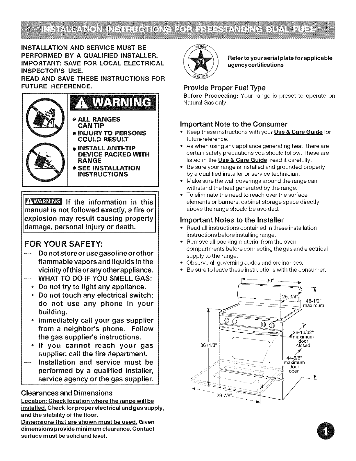
Clearances and Dimensions
Location: Check location where the range will be
installed. Check for proper electrical and gas supply,
and the stability of the floor.
Dimensions that are shown must be used. Given
dimensions provide minimum clearance. Contact
surface must be solid and level.
iMPORTANT SAFETY iNSTRUCTiONS
Installation of this range must conform with local codes or,
in the absence of local codes, with the National Fuel Gas
Code ANSI Z223.1 --latest edition when installed inthe
United States.
When installed in a manufactured (mobile) home,
installation must conform with the Manufactured Home
Construction and Safety Standard, Title 24 CFR, Part 3280
[formerlythe Federal Standard for Mobile Home
Construction and Safety, Title 24, HUD (Part 280)] or, when
such standard is not applicable, the Standard for
Manufactured Home Installations, ANSl/NCSBCS A225.1,
or with local codes.
Proper Installation-- Be sure your appliance is properly
installed and grounded by a qualified technician in
accordance with the National Fuel Gas Code ANSi
Z223= latest edition, or in Canada CAN/CGA B149.1 and
CAN/GGA B149.2, and the National Electrical Code
ANSVNFPA No.70-1atest edition, or in Canada CSA
Standard C22.1, Canadian Electrical Code, Part 1, and
local code requirements. Install only per installation
instructions provided inthe literature package for this
range.
This range has been design certified by CSA International.
As with any appliance using gas and generating heat,
there are certain safety precautions you should follow. You
will find them inthe Use & Care Guide, read it carefully.
Special instructions for appliances installed in the State of
Massachusetts: This appliance can only be installed in the
State of Massachusetts by a Massachusetts licensed
plumber or gas fitter. When using a flexible gas connector,
it must not exceed 3 feet (36 inches) in length. A "T" handle
type manual gas valve must be installed in the gas supply
line to this appliance.
= Be sure your range is installed and grounded
properly by a qualified installer orservice
technician.
= This range must be electrically grounded in
accordance with local codes or, in their absence,
with the National Electrical Code ANSVNFPA No.
70 --latest edition when installed in the United
States. See "Grounding Instructions" on page 7-9 in
the Installation Steps.
= Before installing the range in an area covered with
linoleum or any other synthetic floor covering,
make sure the floor covering can withstand heat at
least 90°F above room temperature without
shrinking, warping or discoloring. Do not installthe
range over carpeting unless you place an insulating
pad or sheet of 1/4-inch thick plywood between the
rangeand carpeting.
• Make sure the wall coverings around the range can
withstand the heat generated by the range.
• Do not obstruct the flow of combustion air at the
oven vent nor around the base or beneath the
lower front panel of the range. Avoid touching the
vent openings or nearby surfaces as they may
become hot while the oven isin operation. This range
requires fresh air for proper burner combustion.
• Do not store items of interest to children in the
cabinets above the range. Children could be
seriously burned climbing on the range to reach items.
• To eliminate the need to reach over the surface
burners, cabinet storage space above the burners
should be avoided.
= Adjust surface burner flame size so it does not
extend beyond the edge of the cooking utensil.
Excessive flame is hazardous.
= Do not use the oven as a storage space. This
creates a potentially hazardous situation.
Never use your range for warming or heating the
room. Prolonged use of the range without adequate
ventilation can be dangerous.
• Do not store or use gasoline or other flammable
vapors and liquids near this or any other appliance.
Explosions or fires could result.
= Reset all controls to the "off" position after using a
programmabletiming operation.
DO NOT MAKE ANY ATTEMPT TO
OPERATE THE ELECTRIC IGNITION OVEN DURING
AN ELECTRICAL POWER FAILURE. RESETALL OVEN
CONTROLS TO "OFF" IN THE EVENT OF A POWER
FAILURE.
The electric ignitor will automatically re-ignite the oven
burner when power resumes if the oven thermostat
control was left in the "ON" position.
When an electrical power failure occurs during use, the
surface burners will continue to operate.
During a power outage, the surface burners can be litwith
a match. Hold a lighted match to the burner, then slowly
turn the knob to the _ (lite)position. Use extreme caution
i
when lighting burners this way.
FOR MODELSWITH SELF-CLEAN FEATURE:
• Remove broiler pan, food and other utensils before
self-cleaning the oven. Wipe up excess spillage. Follow
the cleaning instructions in the Use &Care Guide.
• Unlike the standard gas range, THiS
COOKTOP IS NOT REMOVABLE. Do
not attempt to remove the cooktop.
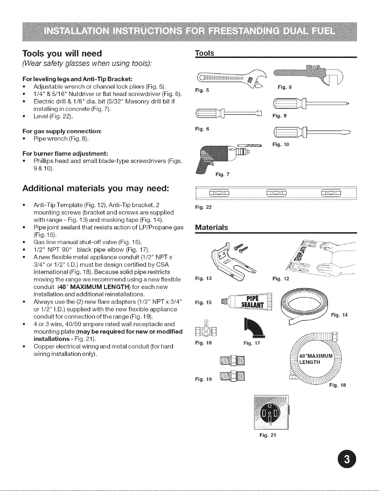
Tools you will need
(Wear safety glasses when using tools):
For leveling legs and Anti=Tip Bracket:
• Adjustable wrench or channel lock pliers (Fig. 5).
1/4" & 5/16" Nutdriver or flat head screwdriver (Fig. 6).
Electric drill & 1/8" dia. bit (5/32" Masonry drill bit if
installing in concrete (Fig. 7).
Level (Fig. 22).
Tools
Fig. 5
For gas supply connection:
Pipe wrench (Fig. 8).
For burner flame adjustment:
Phillips head and small blade-type screwdrivers (Figs.
9& 10).
Fig. 6
Additional materials you may need:
Anti-Tip Template (Fig. 12), Anti-Tip bracket, 2 Fig. 22
mounting screws (bracket and screws are supplied
with range - Fig. 13) and masking tape (Fig. 14).
Pipe joint sealant that resists action of LP/Propane gas
(Fig. 15).
Gas line manual shut-off valve (Fig. 16).
1/2" NPT 90 ° black pipe elbow (Fig. 17).
A new flexible metal appliance conduit (1/2" NPT x
3/4" or 1/2" I.D.) must be design certified by CSA
International (Fig. 18). Because solid pipe restricts
moving the range we recommend using a new flexible
conduit (48" MAXIMUM LENGTH) for each new
installation and additional reinstallations.
Always use the (2) new flare adapters (1/2" NPT x 3/4"
or 1/2" I.D.) supplied with the new flexible appliance
conduit for connection of the range (Fig. 19).
4 or 3 wire, 40/50 ampere rated wall receptacle and
mounting plate (may be required for new or modified
installations - Fig. 21).
= Copper electrical wiring and metal conduit (for hard Fig. 16
wiring installation only).
Materials
Fig. 13_
Fig. 15
Fig. 10
Fig. 7
Fig. 12
Fig. 14
Fig. 17
Fig. 19
010
Fig. 21
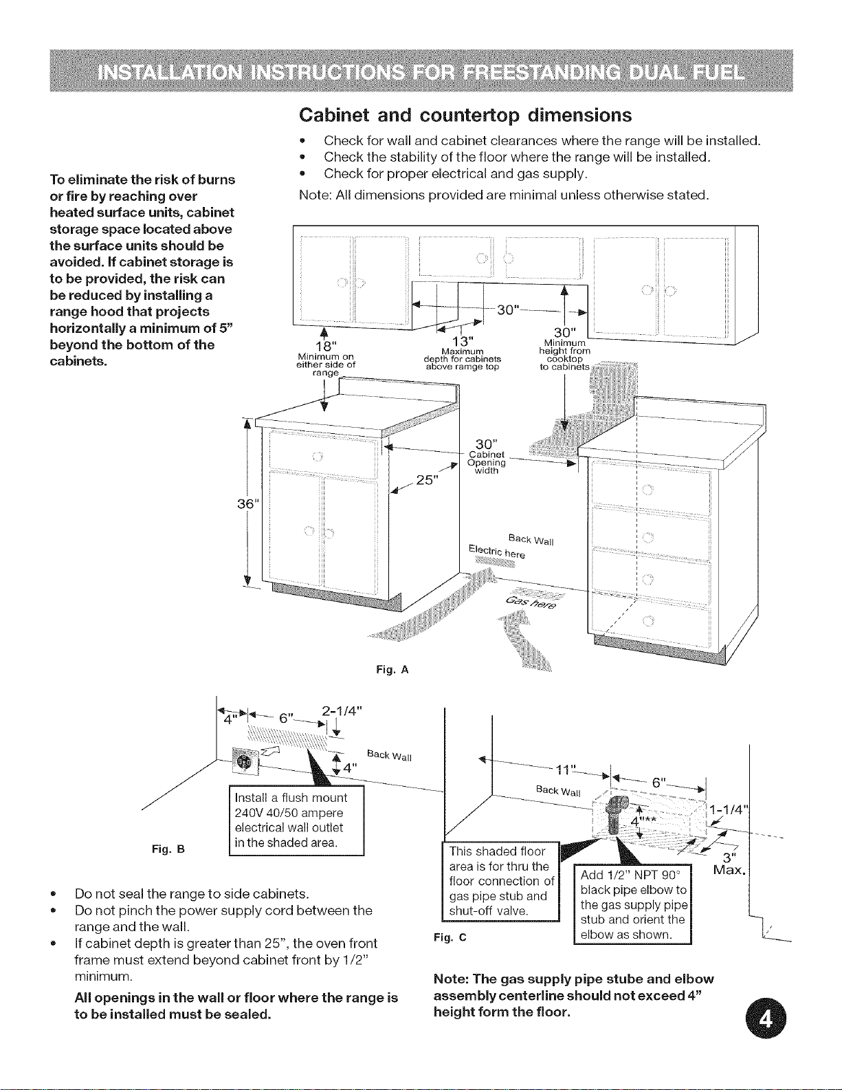
To eliminate the risk of burns
or fire by reaching over
heated surface units, cabinet
storage space located above
the surface units should be
avoided, if cabinet storage is
to be provided, the risk can
be reduced by installing a
range hood that projects
horizontally a minimum of 5"
beyond the bottom of the
cabinets.
Cabinet and countertop dimensions
• Check for wall and cabinet clearances where the range will be installed.
Check the stability of the floor where the range will be installed.
Check for proper electrical and gas supply.
Note: All dimensions provided are minimal unless otherwise stated.
18"
Minimum on
either side of
rang_
Maximum
depth for cabinets
above ramge top
height from
cooktop
to cabinets
i[ i
i ...............
i
Fig. A
Back Wall
Install a flush mount
240V 40/50 ampere
electrical wall outlet
Fig. B
in the shaded area.
Do not seal the range to side cabinets.
Do not pinch the power supply cord between the
range and the wall.
If cabinet depth is greater than 25", the oven front
frame must extend beyond cabinet front by 1/2"
minimum.
All openings inthe wall or floor where the range is
to be installed must be sealed.
Back Wail
BaokWa JJ;"
: _1=1/4"
4"** ;
This shaded flo_ _ 3"
area is for thru the Max.
floor connection of Add 1/2" NPT 90°
gas pipe stub and black pipe elbow to
shut-off valve, the gassupply pipe
Fig. C elbow asshown.
Note: The gas supply pipe stube and elbow
assembly centerline should not exceed 4"
height form the floor.
stub and orient the
---_ _

Installation with cabinets and waft
Fig. D
Anti=tip installation
iMPORTANT SAFETY WARNING!
Anti=tip bracket installation instructions
1. Locate the Bracket Using the Template - (Bracket
may be positioned on either the left or right side of the
range. Refer to Figs. 24 thru 26 to position the bracket
iftemplate isnot available). Mark the floor or wall
where left or right side of the range will be located. If
rear of range is against wall or no further than 1-1/4"
from wall when installed, you may use the wall or floor
mount method. If molding is installed and does not
allow the bracket to fit flush against wall, remove
molding or mount bracket to floor. For wall mount (Fig.
24), locate the bracket by placing the back edge of the
template against rear wall and the side edge of
template on the mark made referencing the side of the
range. Place bracket on top of template and mark
location of the screw holes in wall. If rear of range is
further than 1-1/4" from wall when installed, attach
bracket to the floor. For floor mount (Figs. 24 or 25),
locate the bracket by placing back edge of the
template where the rear of the range will be located.
Mark the location of the screw holes shown in
template.
.
Drill Pilot Holes & Fasten Bracket - Drill 1/8" pilot
hole where screws are to be located (Fig. 23). If
bracket isto be mounted to the wall, drill pilot hole at
an approximate 20 ° downward angle. If bracket isto
be mounted to masonry or ceramic floors, drill 3/16"
pilot hole 1-3/4" deep. The screws provided may be
used in wood or concrete material. Use 5/16" nut-
driver or flat head screwdriver to secure the bracket in
place.
To reduce the risk of tipping of the range, the range
must be secured to the floor by properly installed anti-
tip bracket and screws packed with the range. Failure
to install the anti-tip bracket will allow the range to tip
over if excessive weight is placed on an open door or if
a child climbs upon it. Serious injury might result from
spilled hot liquids or from the range itself.
If range isever moved to a different location, the anti=
tip brackets must also be moved and installed with the
range.
Instructions are provided for installation in wood or
cement fastened to either the floor or wall. When
installed to the wall, make sure that screws completely
penetrate dry wall and are secured in wood or metal.
When fastening to the floor or wall, be sure that
screws do not penetrate electrical wiring or plumbing.
.
Level & Position Range - Level range by adjusting the
(4) leveling legs with a wrench. Note: A min. clearance
of 1/8" is required between bottom of range and
leveling legs to allow room for bracket. Slide range
back into position (Fig. 26). Remove lower panel or
storage drawer to visually check that rear leveling leg
is inserted into and fully secured by the bracket. For
models with a warmer drawer or broiler compartment,
grasp the top rear edge of the range and carefully
attempt to tilt it forward. Use a level to check your
adjustments (Fig. 27).
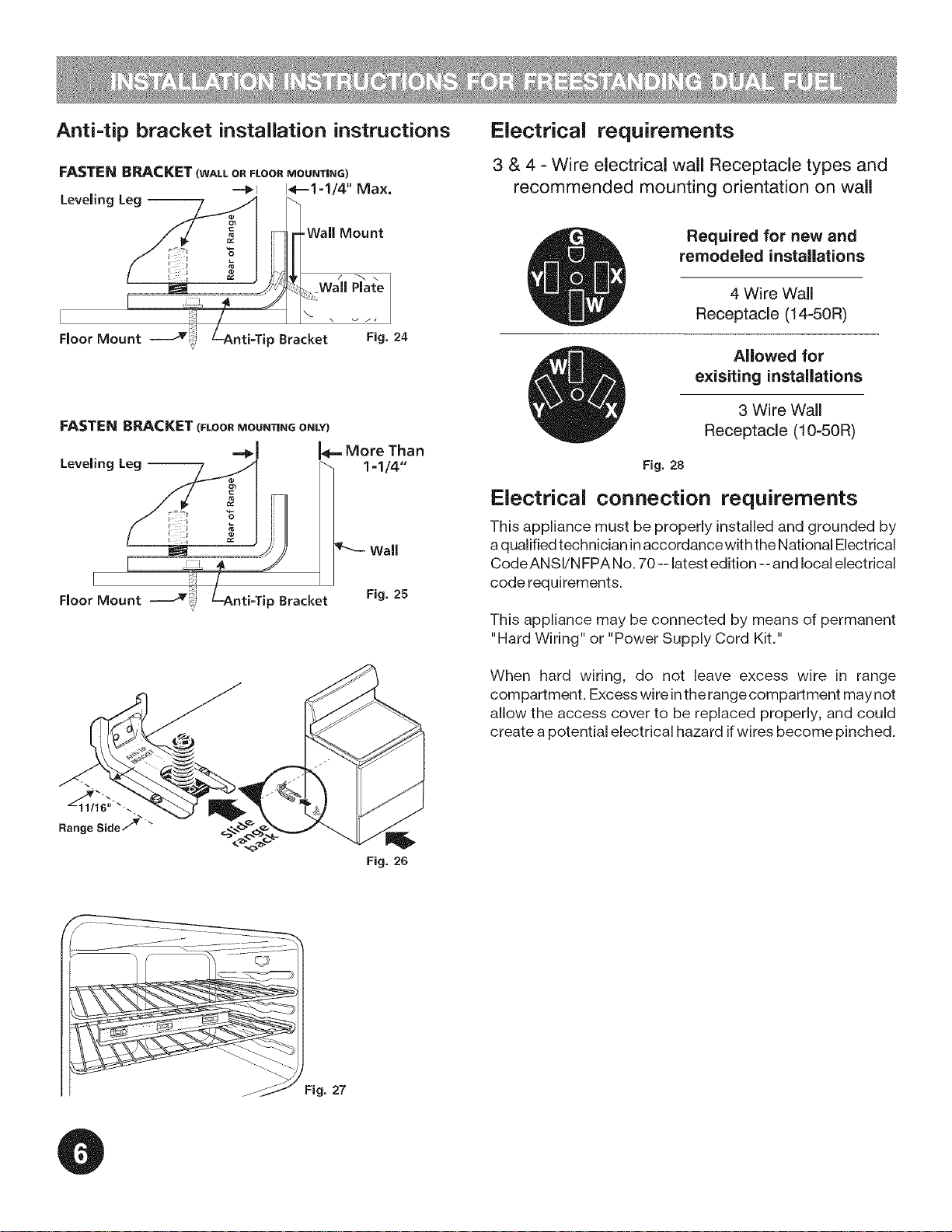
Anti=tip bracket installation instructions
Electrical requirements
FASTEN BRACKET (WALLoRFLOORMOUNTING)
==_l I_==1=1/4'' Max,
LeveJingLeg--
-Wall Mount
Wall Plate
Floor Mount
FASTEN BRACKET (FLOOR MOUNTING ONLY)
p Bracket Fig. 24
"_J I'_" More Than
Leveling Leg -- _- 1 =1/4"'
Wall
I
Floor Mount p Bracket Fig. 25
3 & 4 - Wire electrical wall Receptacle types and
recommended mounting orientation on wall
Required for new and
remodeled installations
4 Wire Wall
Receptacle (14-50R)
Allowed for
exisiting installations
3 Wire Wall
Receptacle (10-50R)
Fig. 28
Electrical connection requirements
This appliance must be properly installed and grounded by
aqualified technician inaccordance with the National Electrical
Code ANSl/N FPA No. 70 -- latest edition -- and local electrical
code requirements.
This appliance may be connected by means of permanent
"Hard Wiring" or "Power Supply Cord Kit."
Range Side7 _
When hard wiring, do not leave excess wire in range
compartment. Excess wire inthe range compartment may not
allow the access cover to be replaced properly, and could
create a potential electrical hazard ifwires become pinched.
Fig. 26
Fig. 27
 Loading...