

Page 1
iNSTALLATiON AND SERVICE MUST BE PERFORMED BYA QUALiFiED iNSTALLER.
iMPORTANT: SAVE FOR LOCAL ELECTRICAL INSPECTOR'S USE.
READ AND SAVE THESE iNSTRUCTiONS FOR FUTURE REFERENCE.
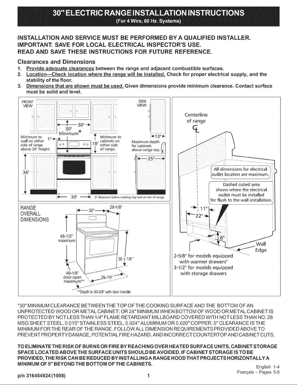
Clearances and Dimensions
1. Provide adequate clearances between the range and adjacent combustible surfaces.
2. Location--Check location where the range will be installed. Check for proper electrical supply, and the
stability of the floor.
3. Dimensions that are shown must be used. Given dimensions provide minimum clearance. Contact surface
must be solid and level.
SIDE
VIEW
................
Minimum to t Minimum to
wall on either 1"-_
side of range
above 36" height.
30"
RANGE
OVERALL
DIMENSIONS
18" cabinets on
either side
of range.
_ O" clearance below cooking top and at rear of range.
T
48-1/2"
maximum
__ 36.+1/8
49-1/8" ...;?.
dooropen \\ .29-7/8"
maximum** \4_''_ /- /
Maximum depth /-:
for cabinets [/'
above range top. _
T
I_13"_I
Wall
Edge
2=5/8" for models equipped "'""
with warmer drawers"
3=1/2" for models equipped
with storage drawers
**Depth is30-318"withdoor handle
*30" MINIMUM CLEARANCE BETWEEN THE TOP OF THE COOKING SURFACE AND THE BOTTOM OF AN
UNPROTECTED WOOD OR METAL CABINET; OR 24" MINIMUM WHEN BOTTOM OF WOOD OR METAL CABINET IS
PROTECTED BY NOT LESS THAN 1/4" FLAME RETARDANT MILLBOARD COVERED WITH NOT LESS THAN NO. 28
MSG SHEET STEEL, 0.015" STAINLESS STEEL, 0.024" ALUMINUM OR 0.020" COPPER. 0" CLEARANCE ISTHE
MINIMUM FOR THE REAR OF THE RANGE. FOLLOW ALL DIMENSION REQUIREMENTS PROVIDED ABOVE TO
PREVENT PROPERTY DAMAGE, POTENTIAL FIRE HAZARD, AND INCORRECT COUNTERTOPAND CABINET CUTS.
TO ELIMINATE THE RISK OF BURNS OR FIRE BY REACHING OVER HEATED SURFACE UNITS, CABINET STORAGE
SPACE LOCATED ABOVE THE SURFACE U NITS SHOULD BE AVOIDED. IF CABINET STORAGE ISTO BE
PROVIDED, THE RISK CAN BE REDUCED BY INSTALLI NG A RANGE HOOD THAT PROJECTS HORIZONTALLY A
MINIMUM OF 5" BEYOND THE BOTTOM OF THE CABINETS. English 1-4
pin 316454924 (1008) 1 Fran_ais - Pages 5-8
Page 2
iMPORTANT SAFETY
iNSTRUCTiONS
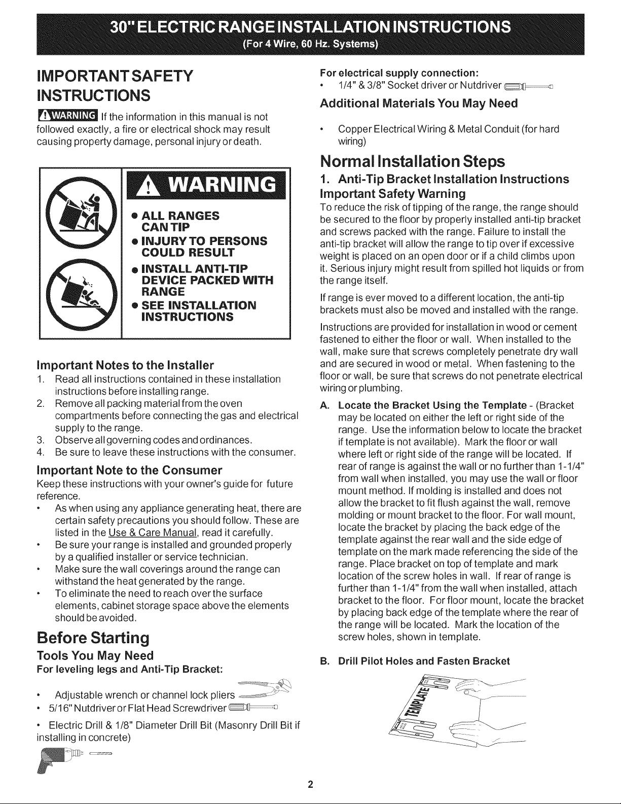
If the information in this manual is not
followed exactly, a fire or electrical shock may result
causing property damage, personal injury or death.
®
ALL RANGES
CAN TiP
®
INJURY TO PERSONS
COULD RESULT
INSTALL ANTI-TIP
O
DEVICE PACKED WITH
RANGE
®
SEE INSTALLATION
INSTRUCTIONS
Important Notes to the Installer
1. Read all instructions contained in these installation
instructions before installing range.
2. Remove all packing material from the oven
compartments before connecting the gas and electrical
supply to the range.
3. Observe all governing codes and ordinances.
4. Be sure to leave these instructions with the consumer.
Important Note to the Consumer
Keep these instructions with your owner's guide for future
reference.
• As when using any appliance generating heat, there are
certain safety precautions you should follow. These are
listed in the Use & Care Manual, read it carefully.
Be sure your range is installed and grounded properly
by a qualified installer or service technician.
Make sure the wall coverings around the range can
withstand the heat generated by the range.
To eliminate the need to reach over the surface
elements, cabinet storage space above the elements
should be avoided.
Before Starting
Tools You May Need
For leveling legs and Anti=Tip Bracket:
For electrical supply connection:
• 1/4" & 3/8" Socket driver or Nutdriver
Additional Materials You May Need
Copper Electrical Wiring & Metal Conduit (for hard
wiring)
Normal installation Steps
1. Anti-Tip Bracket Installation Instructions
Important Safety Warning
To reduce the risk of tipping of the range, the range should
be secured to the floor by properly installed anti-tip bracket
and screws packed with the range. Failure to install the
anti-tip bracket will allow the range to tip over if excessive
weight is placed on an open door or if a child climbs upon
it. Serious injury might result from spilled hot liquids or from
the range itself.
If range is ever moved to adifferent location, the anti-tip
brackets must also be moved and installed with the range.
Instructions are provided for installation in wood or cement
fastened to either the floor or wall. When installed to the
wall, make sure that screws completely penetrate dry wall
and are secured in wood or metal. When fastening to the
floor or wall, be sure that screws do not penetrate electrical
wiring or plumbing.
A,
Locate the Bracket Using the Template - (Bracket
may be located on either the left or right side of the
range. Use the information below to locate the bracket
if template is not available). Mark the floor or wall
where left or right side of the range will be located. If
rear of range is against the wall or no further than 1-1/4"
from wall when installed, you may use the wall or floor
mount method. If molding is installed and does not
allow the bracket to fit flush against the wall, remove
molding or mount bracket to the floor. For wall mount,
locate the bracket by placing the back edge of the
template against the rear wall and the side edge of
template on the mark made referencing the side of the
range. Place bracket on top of template and mark
location of the screw holes in wall. If rear of range is
further than 1-1/4" from the wall when installed, attach
bracket to the floor. For floor mount, locate the bracket
by placing back edge of the template where the rear of
the range will be located. Mark the location of the
screw holes, shown in template.
B. Drill Pilot Holes and Fasten Bracket
• Adjustable wrench or channel lock pliers ......... :_ "
• 5/16" Nutdriveror Flat Head Screwdriver __
Electric Drill & 1/8" Diameter Drill Bit (Masonry Drill Bit if
installing in concrete)
Page 3
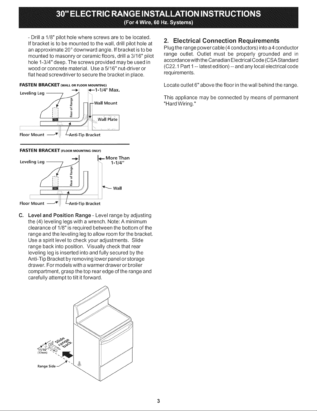
-Drilla1/8"pilotholewherescrewsaretobelocated.
Ifbracketistobemountedtothewall,drillpilotholeat
anapproximate20°downwardangle.Ifbracketistobe
mountedtomasonryorceramicfloors,drilla3/16"pilot
hole1-3/4"deep.Thescrewsprovidedmaybeusedin
woodorconcretematerial.Usea5/16"nut-driveror
flatheadscrewdrivertosecurethebracketinplace.
2. Electrical Connection Requirements
Plug the range power cable (4conductors) intoa4 conductor
range outlet. Outlet must be properly grounded and in
accordance with the Canadian Electrical Code (CSA Standard
(C22.1 Part 1-- latest edition) -- and any local electrical code
requirements.
FASTEN BRACKET (WALL OR FLOOR MOUNTING)
Leveling Leg --
i \ \ _ /,
Floor Mount _ p Bracket
Floor Mount _ p Bracket
C=
Level and Position Range - Level range by adjusting
-=_1 I,_==1=1/4'' Max.
Wal Plate
the (4) leveling legs with a wrench. Note: A minimum
clearance of 1/8" is required between the bottom of the
range and the leveling leg to allow room for the bracket.
Use a spirit level to check your adjustments. Slide
range back into position. Visually check that rear
leveling leg is inserted into and fully secured by the
Anti-Tip Bracket by removing lower panel or storage
drawer. For models with a warmer drawer or broiler
compartment, grasp the top rear edge of the range and
carefully attempt to tilt itforward.
Locate outlet 6" above the floor in the wall behind the range.
This appliance may be connected by means of permanent
"Hard Wiring."
(17turn)
Range Side _""
Page 4

Model and Serial Number Location
The serial plate is located on the right-hand surface of the oven
front frame atthe storage or warmer drawer; orthe lower panel
area.
When ordering parts for ormaking inquires about your range,
always be sure to include the model and serial numbers and
a lot number or letter from the serial plate on your range.
Your serial plate also tells you the Kilowatt rating (power
requirements) and Voltage ratings
Care, Cleaning and Maintenance
Refer to the Use & Care Manual for cleaning instructions.
Ifremoving the range is necessary for cleaning or maintenance,
disconnect the electrical power supply. Ifthe electrical supply
is inaccessible, lift the unit slightly at the front and pull out
away from the wall. Pull only as far as necessary tod isconnect
the electrical supply. Finish removing the unit for servicing and
cleaning. Reinstall in reverse order making sure to level the
range and check electrical connections. See pages 2 and 3
for proper anchoring instructions.
Before You Call for Service
Read the "Before You Call" and operating instruction sections
inyour Use & Care Manual. Itmay save you time and expense.
The list includes common occurrences that are not the result
of defective workmanship or materials in this appliance.
Refer to the warranty in your Use & Care Manual for our toll-free
service number and address. Please call or write ifyou have
inquiries about your range product and/or need to order parts.
Page 5

L'INSTALLATION ET L'ENTRETIEN DOIVENT ETRE EFFECTUi_S PAR UN INSTALLATEUR QUALIFI¢:
iMPORTANT: A CONSERVER POUR CONSULTATION PAR L'INSPECTEUR EN leLECTRICITle.
LISEZ ET CONSERVEZ CES iNSTRUCTiONS POUR CONSULTATION FUTURE.
Dimensions et espaces iibres
1. Laissez des espaces libres ad6quats entre la cuisini_re et les surfaces combustibles adjacentes.
2. LocalisationiV6rifiez I'endroit o_ la cuisini6re sera install6e. Assurez vous que les alimentations d'61ectricit6
sont ad6quates et que le plancher est solide.
3. Les distances indiqu_es doivent 6tre ap_pliqu6es. Les distances donn6es sont minimales. La surface de support
doit _tre solide et au niveau.
Ligne de Centre
de la cuisini_re
q_
i
1
i
t i
1
! . ..........(_ Toutes les dimensions de
---'_ | remplacement de la sortie | ::
', [ _lectrique sont maximales
t ! I
i
La r_gion de la boite pointill_e
rnontre la localisation de la sorti_
_lectrique pour une installation
contre le tour
Espace minimum 1 "-I_
aux c6t_s de ia
cuisini&re, au dessus
de 914mm (36")
, _
DIMENSIONHORS
_"............_, g, des armoires de
__ l- chaque c6t_ de
I_--- 30"
t Distance rain.
_ _ la cuisini_re
Aucun espace requis sous ia surface de cuisson et
I'arriere de la cuisini_re.
28-1/8"
Profondeur max. des
14-13"_1
armoires au dessus F
de la cuisini_re l!
i i
TOUTE LA
CUIINIERE
T
48-1/2"
maximum
Mur
__. 16+ 1!8
Porteouverte:\ ..-_/_ >
49-1/8"maximum \4_-._ _ __
. **\ .....29=7/8"
ii
\\
67ram (2-5/8")pourlesmodules ""'-
_quip4s avec tiroirs chauffants
89ram (3=1/2") pour les modules
4quip_s avec des tiroirs de
stockage
_rofondeur estde30-3/8"
comprenantlapoigneedelaporte.
"762mm (30") MINIMUM D'ESPACE LIBRE DOIVENT Ft:TRELAISS#S ENTRE LA PARTIE SUPC:RIEURE DE LASURFACE DE CUISSON ET
LE DESSOUS D'UNE ARMOIRE DE BOIS OU DE MC:TAL NON PROTEGe:; OU UN MINIMUM DE 610mm (24") LORSQUE LE DESSOUS DE
L'ARMOIRE DE BOIS OU DE M€:TAL EST PROTEGe: PARAU MOINS 1/4" DE CELLODERME IGNIFUGE RECOUVERT PAR UNE FEUILLE
D'ACIER D'AU MOINS 28 DE JAUGE, D'ACIER INOXYDABLE DE 0.015", D'ALUMINIUM DE 0.024" OU DE CUIVRE DE 0.020". L'ESPACE
LIBRE EST LE MINIMUM POUR L'ARRIERE DE LA CUISINIERE. SUIVEZ TOUTES LES EXIGENCES DE DIMENSIONS FOURNIES CI-
DESSUS AFIN D'#VITER LES DOMMAGES ,ik LA PROPRIC:T¢:, LES RISQUES D'INCENDIE AINSI QUE DES COUPES ERRONIeES
D'ARMOIRES ET DE DESSUS DE COMPTOIR.
DESARMOIRES D'ESPACE DERANGEMENT SITUleESAU=DESSUS DES UNITIeSDESURFACE DEVRAIENT ETRE IeVITIeESAFIN D'IeLIMINER
LES RISQUESDEBROLURES OU D'INCENDIE ENTENDANT LA MAIN PAR=DESSUSLES UNITIESDE SURFACE CHAU DES. LERISQUE PEUT
IETRERIEDUITENINSTALLANT UNE HOTTE DE CUISINIIEREQUI DIEPASSEHORIZONTALEMENT D'AU MOINS 127mm (5") LEDESSOUS DES
ARMOIRES SiDESARMOIRES D'ESPACE DE RANGEMENTSONTINSTALLIEES.
English - Pages 1-4
5
Frangais - Pages 5-8
Page 6

DiRECTiVES IMPORTANTES DE
Si CURITi
Unfeu ou une electrocution peut su rvenir et 6tre
la cause de dommages a la propriete, de blessures ou
entraTner la mort si les instructions de ce manuel ne sont pas
suivies a la lettre.
®
TOUTES LESCUISINIERES
PEUVENT ETRERENVERSEES
®
DES BLESSURESPEUVENT
EN RESULTER
®
INSTALLEZ LE DiSPOSiTIF
DE CONTRE=RENVERSEMENT
EMBALLE AVEC LA CUISINll=RE
®
VOIR LES INSTRUCTIONS
D'INSTALLATION
Notes importantes _ I'installateur
1. Lisez toutes les instructions contenues dans cette notice
d'installation avant d'installer la cuisini_re.
2. Retireztout mat@iau d'empaquetage des cavit6s du fourneau
avant d'alimenter la cuisini_re en 61ectricit6.
3. Respectez tousles codes et ordonnances applicables.
4. Assurez-vous de laisser ces instructions au consommateur.
Note importante au consommateur
Conservez ces instructions avec votre guide du consommateur pour
consultation future.
• IIy a certaines pr6cautions de s6curit6 que vous devez respecter
Iorsque vous utilisez des appareils produisant de la chaleur.
Celles-ci sont inscrites dans lemanuel d'utilisation et d'entretien,
lisez-le soigneusement.
• Soyez certain que votre cuisini_re est correctement install6e et
mise _ la terre par un installateur ou un technicien de service
qualifi6.
• Assurez-vous que les rev_tements muraux autours de la
cuisini@e peuvent endurer la chaleur produite par la cuisini_re.
• Les armoires de rangement au-dessus de la cuisini_re devraient
_tre 6vit6es afin d'61iminer le besoin de tendre la main au-
dessus des 616ments chauffants.
Avant de commencer
Outils dont vous aurez besoin
Pour les pattes de raise _niveau et lesupport de contrerenversement
........
• CI6 r6glable ou pince multiprise ordinaire :::;_
• Tourne-6crou de 5/16" ou tournevis plat (_
• Perceuse 61ectrique et m_che de perceuse de 1/8" de
diam_tre. (m_che pour la magonnerie de 5/32" si vous installez
dans le b6ton).
Pour le raccordement de I'alJmentatJon electrique :
• Des tourne-6crous ou douilles de 1/4" et 3/8"
IVlat_riel suppl6mentaire dont vous aurez besoin
• Un cordon d'alimentation de puissance ou
• Filage 61ectrique de cuivre et conduit m6tallique (pour
connexion sans prise).
€:tapes normales d'installation
1. instructions de montage du support de contre-
renversement
La cuisini@edoit &trefix6e au plancher par I'installation ad6quate de vis
et de support de contre-renversement empaquet6s avec la cuisini_re
afin de reduire le risque de renversement de celle-ci. La cuisini@e peut
s'incliner si un poids excessif est plac6 sur une porte ouverte ou si un
enfant monte sur laporte, si vous n6gligez d'installer lesupport de contre-
renversement. Des blessures s@ieuses peuvent r6sulter de liquides
brGlants renvers6s ou par la cuisini@e elle-m&me.
Le support de contre-renversement doit aussi _tre d6plac6 et install6
avec la cuisini@e si celle-ci est relocalis6e.
Des instructions sont foumies pour une installation sur du bois ou du
ciment, fix6e soit au plancher ou au mur. Assurez-vous que les vis
p6n_trent compl_tement la cloison du mur et qu'elles sont bien ancr6es
dans le bois ou le m6tal, Iorsque I'installation est faite au mur. Assurez-
vous que les vis ne traversent pas la plomberie ou des fils 61ectriques
durant la fixation au plancher ou au mur.
A.
Situez le supporten utJlisant le gabarit= (Le support peut &tre
Iocalis6 _ gauche ou _ droite de la cuisini_re. Utilisez
I'information donn6e ci-apr_s pour situer le support si le
gabarit n'est pas disponible.) Marquez le plancher ou le mur
I'endroit o_ le c6t_ gauche ou droit de la cuisini_re sera
situS. Vous pouvez utiliser la m_thode de montage au murou
au plancher si I'arri_re de la cuisini_re est appuy_ au mur ou
pas plus _loign_ du mur que 3 cm (1 1/4") apr_s installation.
Enlevez la moulure ou fixez le support au plancher si une
moulure est install&e et ne permet pas au support de
s'appuyer fermement sur le mur. Pour un montage contre le
mur, situez le support en plagant la partie arri_re du gabarit
contre lemur arri_re et le bord du gabarit sur la marque faite
qui identifie le c6t_ de la cuisini_re. Placez le support par-
dessus le gabarit et identifiez I'emplacement des trous des
vis dans le mur. Fixez le support au plancher si I'arri_re de la
cuisini_re est plus _loign_ que 3 cm (1 1/4") du mur apr_s
I'installation. Situez le support en plagant la partie arri_re du
gabarit _ I'endroit o_ I'arri_re de la cuisini_re sera Iocalis_
pour un montage sur le plancher. Marquez I'emplacement
des trous des vis indiqu_s sur le gabarit.
B. Percez les trous d'alignement et fixez le support -
Page 7

Percez un trou de 3 mm (1/8") aux endroits oQ les vis
seront Iocalis6es. Percez un trou d'alignement a un angle
descendant d'approximativement 200 si le support doit
6tre installe sur le tour. Percez un trou d'alignement de
4.76 mm (3/16") par 44 mm (1-3/4") de profondeur si le
support doit _tre installe dans la magonnerie ou des
planchers de ceramique. Les vis fournies peuvent _tre
utilisees dans le bois ou des materiaux en b6ton. Utilisez
un serre ecrou ou un tournevis plat afin de fixer le support
en place.
Plaque
Murale
Montage au _
plancher
FiXEZ LE SUPPORT (MONTAGE AU PLANCHER SEULEMENT)
Patte de
niveau
- Support de
contre-renversement
2. Exigences du raccordement _lectrique
Branchez le cable 61ectrique de cuisini_re a une sortie de
foumeau de 4 conducteurs. La sortie doit _tre correctement
fondue et selon canadien electrique le code (Piece C22.1 1,
la derni_re edition standard de CSA) - et toutes conditions
electriques locales de code.
Localisez la sortie 6" au-dessus du plancher dans lemur
derriere le fourneau.
h
Montage au _ - Support de
plancher contre=renversement
C=
Mise en place et & niveau de la cuisiniCre - Mettez la
cuisiniere a niveau en ajustant les (4) pattes de raise
niveau a I'aide d'une cle a molette. Note: Un espacement
minimum de 3 mm (1/8") est NOTICE D'INSTALLATION
POUR CUISINIERE €:LECTRIQUE DE 762mm (30") (pour
les syst_mes 60 Hz a 3 ou 4 fils)requis entre le bas de la
cuisiniere et la patte d'ajustement afin de permettre un
espace pour le support. Utilisez un niveau a bulle pour
verifier vos ajustements. Glissez la cuisini_re vers sa
position. Verifiez visuellement que la patte de raise
niveau arri_re est completement ins6r6e et fixee dans le
support de contre-renversement en retirant le panneau
inferieur ou le tiroir de rangement. Saisissez la partie
sup6rieure arri_rede lacuisini_re etessayez prudemment
de lafaire basculervers I'avant, pour lesmodeles possedant
un tiroir-rechaud ou une r6tisserie.
Cet appareil peut 6tre relie a I'aide "du c_blage dur
permanent."
Page 8

Emplacement du no. de module /
no. de s_rie
La plaque signal6tique est Iocalisee sur lasurface a droite du
devant du cadredu fourneau, a la partie inferieuredu panneau
derriere le devant du tiroir rechaud ou de rangement.
Assurez vous de toujours fournir le no. de modele et de serie
ainsi que le no. de lotou lettre sur la plaque d'identification de
votre cuisiniere Iorsque vous commandez des pi_ces ou
demandez de I'information concernant votre cuisini_re
Votre plaque signal6tique vous indique aussi la capacite en
Kilowatts (exigence de puissance) et la tension nominale.
Soins, nettoyage et entretien
Pour les instructionde nettoyage, ref6rez vous a votre Guide
d'utilisation et d'entretien.
Debranchez I'alimentation de puissance electrique s'il est
necessaire de deplacez la cuisini_re pour le nettoyage ou
I'entretien. Soulevez legerement I'appareil a I'avant ettirez afin
de I'eloigner du tour si I'acces a I'alimentation electrique est
inaccessible. N'eloignez du murquede la distance necessaire
pour debrancher I'alimentation electrique. Finissez de deplacer
I'appareil pour I'entretien et le nettoyage. Reinstallez en ordre
inverse en vous assurant de mettre la cuisiniere a niveau et
verifiez les raccordements electriques. Voyez les pages 2 et
3 pour les instructions correctes d'ancrage.
Avant que vous ne fassiez un
.......................
)
Emplacement de la plaque signaletique
Ouvrez le tiroir-rechaud ou de rangement
ou enlevez le panneau inferieur
(sur certains modeles)
appel de service
Lisez "Avant d'appeler" et les sections de notices d'op6ration
de votre Guide d'utilisation et d'entretien, ils peuvent vous
sauver temps etargent. IIs comprennent des occurrences qui
ne parviennent pas de defaut de materiau ou de main-d'oeuvre
dans cet appareil.
Pour conna_tre notre no. de telephone sans frais et notre
adresse, ref6rezvous a lagarantiedansvotreGuided'utilisation
et d'entretien. Si vous avez des questions concernant votre
cuisini_re et/ou devez commander des pieces de rechange
n'hesitez pas a nous tel6phoner ou a nous ecrire
 Loading...