

Electrolux Built-in Ovens, Built-in Oven Service Manual
SOI 04.04 FV 1/50 599 35 96-40
SERVICE MANUAL
COOKING
THIS MANUAL UPDATES AND REPLACES THE
PREVIOUS EDITION (SAME CODE)
ELECTROLUX HOME PRODUCTS
Corso Lino Zanussi,30
Publication
number
I. 33080 PORCIA /PN (ITALY)
599 35 96-40
Tel +39 0434 394850
Fax +39 0434 394096
SOI
Edition: 04.2004
IT/SERVICE/FV
Built-in Ovens
ACCESS TO THE
"ACCESS"
STRUCTURE”

SOI 04.04 FV 2/50 599 35 96-40

SOI 04.04 FV 3/50 599 35 96-40
CONTENTS
1. INTRODUCTION --------------------------------------------------------------------- 5
1.1. PURPOSE OF THIS MANUAL ------------------------------------------------------ 5
2. ELECTRIC/ELECTRONIC OVENS --------------------------------------------- 5
2.1. DISMANTLING BUILT-IN OVENS ----------------------------------------------- 5
2.2. DISCONNECTING FROM THE POWER SUPPLY-------------------------- 6
2.3. REMOVING THE CONTROL PANEL ------------------------------------------- 6
2.4. REMOVING THE REAR PANEL ------------------------------------------------- 7
2.4.1. REMOVING THE TERMINAL BLOCK.---------------------------------------------------- 7
2.4.2. REMOVING THE SPIT MOTOR ------------------------------------------------------------ 8
2.4.3. REMOVING THE CONVECTION FAN ---------------------------------------------------- 8
2.4.4. REMOVING THE CONNECTION FAN BLADES --------------------------------------- 8
2.4.5. ACCESS TO THE FAN BLADES AND THE CIRCULAR HEATING ELEMENT 9
2.4.6. REMOVING THE LAMP SOCKET --------------------------------------------------------- 9
2.5. REMOVING THE FRONT PANEL SEAL. -------------------------------------- 10
2.6. UPPER PANELS (control components and circuit boards)---------------- 11
2.6.1. UPPER PANEL---------------------------------------------------------------------------------- 11
2.6.2. UPPER PANEL (fan and safety thermostat) --------------------------------------------- 14
2.7. REMOVING THE LATERAL UPRIGHTS OF THE CONTROL PANEL 15
2.8. REMOVING THE NORMAL OVEN DOOR ------------------------------------ 16
2.8.1. REMOVING THE EXTERNAL GLASS PANEL ----------------------------------------- 17
2.8.2. REMOVING THE OVEN DOOR HANDLE ----------------------------------------------- 18
2.8.3. REMOVING THE CENTRAL GLASS PANEL (DOORS WITH 3 PANELS)------ 18
2.9. REMOVING THE FOLDING OVEN DOOR------------------------------------ 19
2.9.1. REMOVING THE TERMINAL COVERS -------------------------------------------------- 20
2.10. HEATPROOF GLASS PANELS -------------------------------------------------- 24
2.11. REMOVING THE FRONT PANEL ----------------------------------------------- 25
3. GAS OVENS -------------------------------------------------------------------------- 28
3.1. REMOVING THE BUILT-IN OVEN ---------------------------------------------- 28
3.2. DISCONNECTING THE OVEN FROM THE POWER SUPPLY---------- 28
3.3. DISCONNECTING THE GAS SUPPLY ---------------------------------------- 28
3.4. REMOVING THE CONTROL PANEL ------------------------------------------- 29
3.5. REMOVING THE REAR PANEL ------------------------------------------------- 30
3.5.1. SMONTAGGIO PCB. -------------------------------------------------------------------------- 31
3.6. REMOVING THE FRONT SEAL.------------------------------------------------- 32
3.7. UPPER PANELS --------------------------------------------------------------------- 32
3.7.1. SMALL UPPER PANEL ----------------------------------------------------------------------- 32
3.7.2. REMOVING THE GRILL CUT-OFF MICROSWITCH AND THE "ON" MICROSWITCH 33
3.7.3. UPPER PANEL---------------------------------------------------------------------------------- 33
3.7.4. REMOVING THE GAS THERMOSTAT (electromechanical versions only) ----- 35
3.7.5. REMOVING THE GAS SOLENOID VALVE (electronic versions only) ----------- 37
3.8. REMOVING THE LATERAL FRONT PANEL UPRIGHTS ----------------- 39

SOI 04.04 FV 4/50 599 35 96-40
3.9. REMOVING THE OVEN BURNER. --------------------------------------------- 39
3.9.1. REMOVING THE IGNITER ------------------------------------------------------------------ 41
3.9.2. REMOVING THE IGNITER / THERMOCOUPLE SUPPORT ---------------------- 41
3.9.3. REMOVING THE OVEN THERMOCOUPLE -------------------------------------------- 42
3.10. REMOVING THE GRILL BURNER PROTECTION-------------------------- 43
3.11. REMOVING THE GRILL BURNER ---------------------------------------------- 43
3.12. REMOVING THE INJECTORS --------------------------------------------------- 45
3.12.1. REMOVING THE OVEN BURNER INJECTOR----------------------------------------- 45
3.12.2. REMOVING THE GRILL BURNER INJECTOR----------------------------------------- 47
3.13. ADJUSTING THE MINIMUM SETTING OF THE OVEN BURNER. ----- 48
4. ORGANIZATION OF ACCESS / KRONOS SERVICE MANUALS ----- 50
SOI 04.04 FV 5/50 599 35 96-40
1. INTRODUCTION
1.1 - PURPOSE OF THIS MANUAL
The purpose of this Manual is to provide a general outline of the methods of accessing the
various versions of ACCESS ovens.
2 - ELECTRIC / ELECTRONIC OVENS
2.1 - DISMANTLING BUILT-IN OVENS
IMPORTANT: Always disconnect the appliance from the power socket before accessing
internal parts.
Access to certain components is possible by pulling the oven partially out of the compartment.
With the oven partially pulled out, the service engineer can access the components of the
front panel and the electronic control unit; for access to the other components located in the
rear section, it is necessary to remove the built-in oven completely from its compartment.
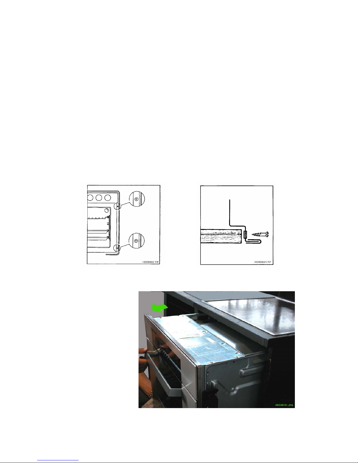
To remove the oven:
1. Remove the 4 screws, located at the front of the front panel, which secure the appliance to
the compartment (see Fig. 1 and 2)
Fig. 1 Fig. 2
2. Remove the oven
(Fig. 3).
Fig. 3
SOI 04.04 FV 6/50 599 35 96-40
2.2. DISCONNECTING FROM THE POWER SUPPLY
IMPORTANT: Before accessing any of the components inside the oven, it is essential to
disconnect the oven from the power supply by removing the plug from the power socket or by
turning the main switch on the domestic circuit (if featured) to "OFF".
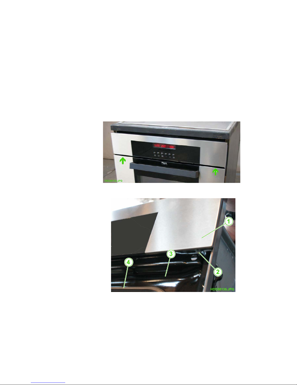
2.3 - REMOVING THE CONTROL PANEL
In order to remove the control panel, first remove the rubber knob caps and, where featured,
the knobs.
1. Open the oven door.
2. Slide off the rubber knob caps (and the control knobs).
3. Remove the two screws from the lower section of the front panel (see Fig. 4 and 5).
4. Slide the control panel upwards and release from the upper retaining tabs.
Fig. 4
Positions of the
screws which secure
the front panel
Fig. 5
1 - CONTROL PANEL
2. SCREW
3. OVEN FRONT
PANEL
4. FRONT PANEL
SEALING RING

SOI 04.04 FV 7/50 599 35 96-40
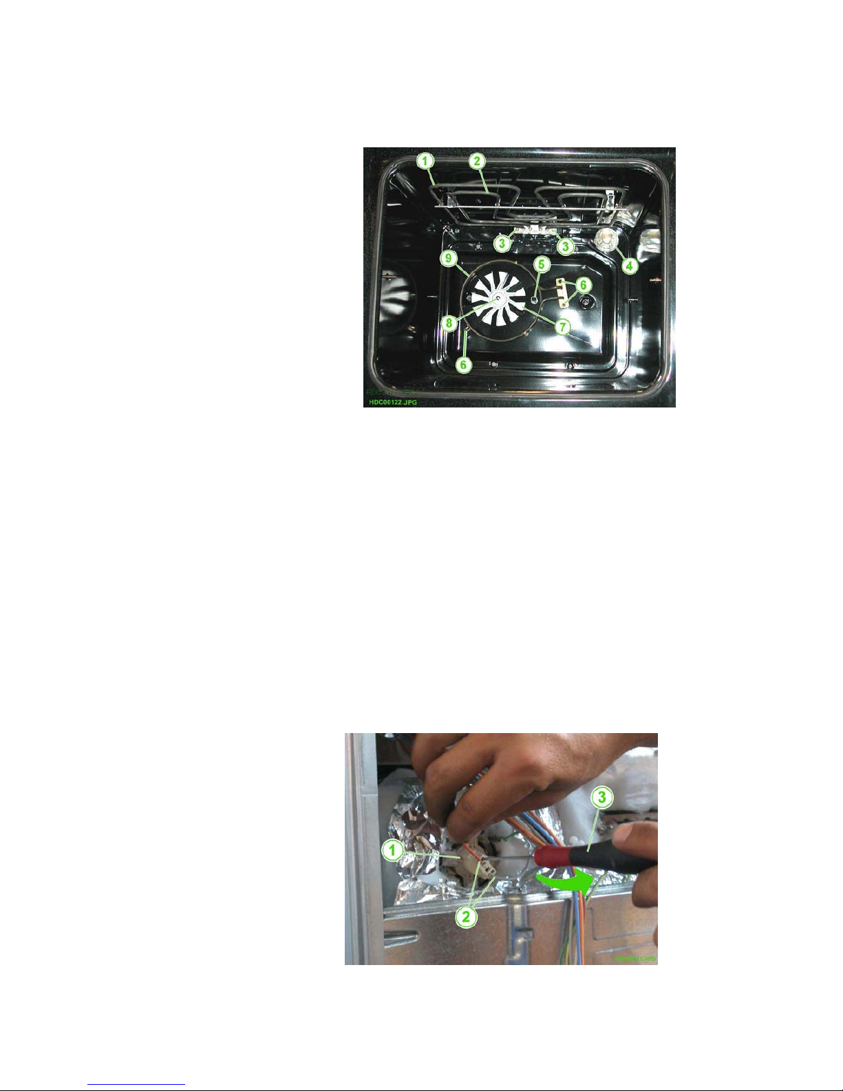
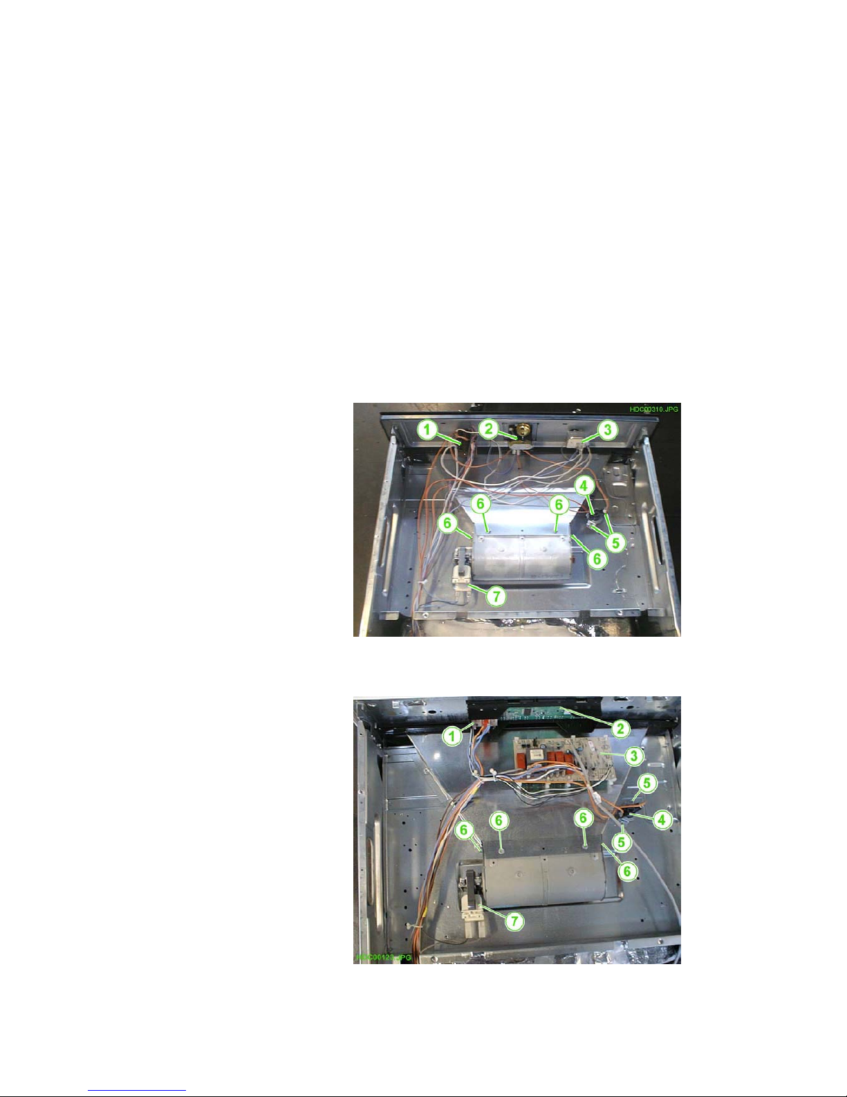
2.4. REMOVING THE REAR PANEL (VARIOUS COMPONENTS AND LAMP-
HOLDER)
In order to remove the rear panel, it is sufficient to remove the two upper screws.
After removing the rear panel, the following components are accessible: the lamp-holder, the
various heating elements, the convection fan motor, the spit motor, the terminal block/cable
clamp, and the PT500 oven sensor.
Fig. 6
1. LAMP-HOLDER
2. TOP PANEL HEATING ELEMENT
3. GRILL HEATING ELEMENT
4. TERMINAL BLOCK
5. CABLE CLAMP
6. CONVECTION HEATING ELEMENT
7. LOWER HEATING ELEMENT
8. SPIT MOTOR
9. CONVECTION FAN
10. PT500 OVEN SENSOR
2.4.1 - REMOVING THE TERMINAL BLOCK
The terminal block for the electrical connections is pressure-fitted into its housing.
To remove the terminal block, use a screwdriver to lever open the anchor tab.
Fig. 7
1. TERMINAL BLOCK
2. CONNECTION FOR LIVE WIRE
3. CONNECTION FOR NEUTRAL
WIRE
4. HOLE FOR ANCHOR TAB
5. EARTH CONNECTION
6. CABLE CLAMP
7. CABLE CLAMP SCREWS
SOI 04.04 FV 8/50 599 35 96-40
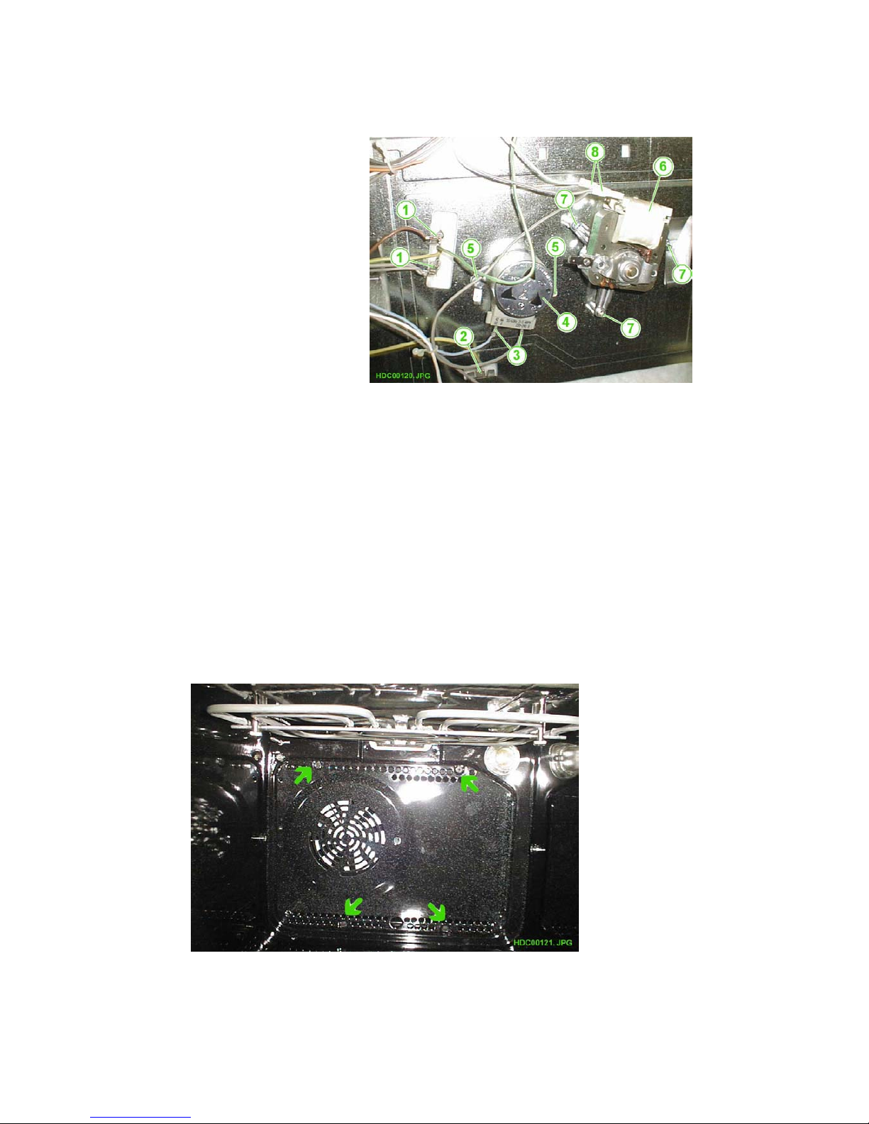
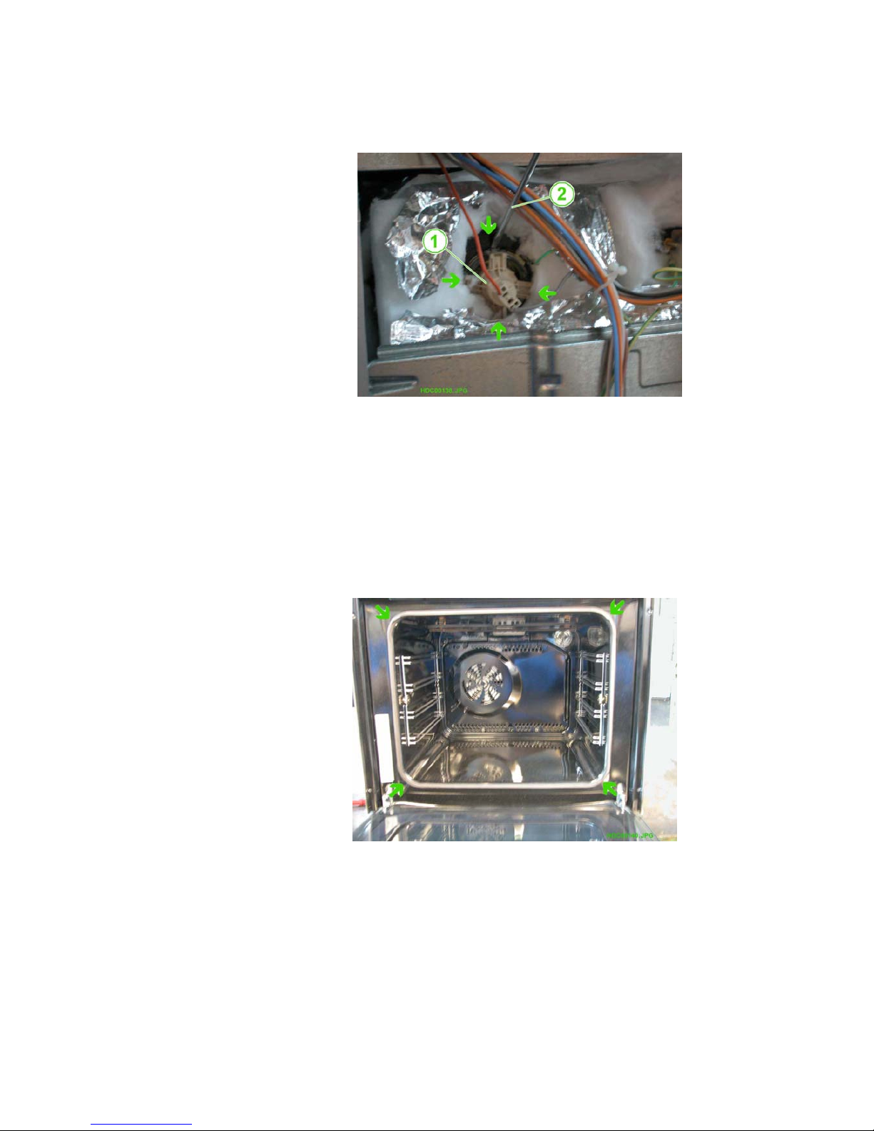
2.4.2. REMOVING THE SPIT MOTOR
In order to remove the spit motor, it is sufficient to unscrew the two screws which secure it in
position (see fig. 8, pos. 5).
Fig. 8
1 - CONVECTION HEATING
ELEMENT
2. EARTH CONNECTION
3. CONNECTION FOR SPIT
MOTOR
4. SPIT MOTOR
5. SPIT MOTOR ANCHOR
SCREWS
6. CONVECTION FAN
7. CONVECTION FAN ANCHOR
SCREWS
8. CONNECTION FOR
CONVECTION FAN
2.4.3 - REMOVING THE CONVECTION FAN
Proceed as follows to remove the convection fan:
1 Remove the fan blade assembly from the inside of the oven (see fig. 10, page 8).
2 Detach the connector wires (carefully mark their position).
Remove the three screws which secure the fan in position (fig. 8, pos. 7).
2.4.4 - REMOVING THE CONVECTION FAN BLADES
Proceed as follows to remove the convection fan blades:
Remove the grilles and the drip pan from the inside of the oven.
Unscrew the four screws (fig. 9) and remove the bottom panel from inside the oven.
Fig. 9
SOI 04.04 FV 9/50 599 35 96-40
2.4.5 - ACCESS TO THE FAN BLADE AND THE CIRCULAR HEATING ELEMENT
First, remove the panel from the inside of the oven. This gives access to the convection fan
and the circular convection heating element.
Fig. 10
1 - UPPER HEATING ELEMENT
2. GRILL HEATING ELEMENT
3. SCREWS SECURING THE
UPPER/GRILL HEATING
ELEMENTS
4. LAMP-HOLDER
5. HOLE FOR SPIT MOTOR
ANCHOR
6. SCREWS SECURING THE
CONVECTION HEATING
ELEMENT
7. SCREWS SECURING THE
CONVECTION FAN
8. CONNECTION FOR
CONVECTION FAN
9. CONVECTION HEATING
ELEMENT
In order to remove the convection heating element, first remove the rear panel. Then:
1. From the rear section of the oven, detach the connector wires and carefully mark their
positions (see fig. 6, pos. 6).
Remove the two screws (located inside the oven) (see fig. 10, pos).
Proceed as follows to remove the convection fan:
1 - Remove the central screw while holding the fan blades in position.
IMPORTANT: The screw is threaded in the opposite direction, i.e. must be turned counter-
clockwise to tighten)
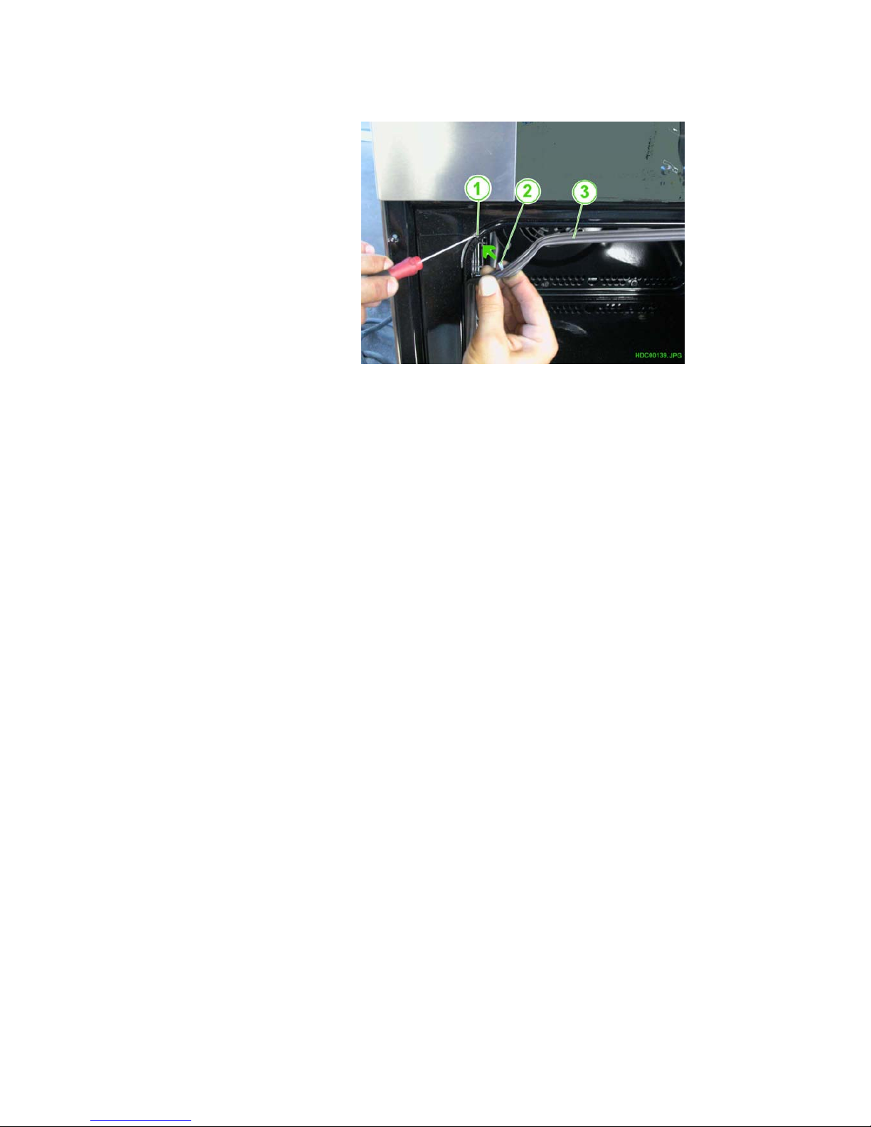
2.4.6 - REMOVING THE LAMP-HOLDER
Remove the rear panel, then proceed as follows to remove the lamp-holder:
1 - Using a screwdriver with a 3mm tip, detach the connector wires.
Fig. 11
1 - LAMP-HOLDER
2 - CONNECTOR WIRES
3 - 3mm SCREWDRIVER
SOI 04.04 FV 10/50 599 35 96-40
2. Using a standard screwdriver, lever open the anchor tabs and release the lamp-holder
(see Fig. 12).
Fig. 12
1 - LAMP-HOLDER
2 - SCREWDRIVER
N.B.: The arrows indicate the
positions of the anchor
tabs
2.5 - REMOVING THE FRONT PANEL SEALING RING
In order to remove the front panel sealing ring, it is sufficient to detach the four anchor
elements from the relative holes, and pull the sealing ring outwards (see Fig. 13 and 14).
Fig. 13
ANCHOR POINTS FOR THE
FRONT PANEL SEALING
RING
SOI 04.04 FV 11/50 599 35 96-40
Fig. 14
1 - HOLE FOR SECURING
THE ANCHOR ELEMENT
2 - SEALING RING ANCHOR
ELEMENT
3 - FRONT PANEL SEALING
RING
2.6 - UPPER PANELS (CONTROL COMPONENTS AND CIRCUIT BOARDS)
The upper section features two panels.
The smaller panel gives access to the electronic circuit boards and the control components;
the larger panel covers the tangential cooling fan.
2.6.1 - SMALL UPPER PANEL (CONTROL COMPONENTS AND CIRCUIT BOARDS)
Removal of the smaller panel provides access to the electronic circuit boards:
- in the electromechanical version, the control components (oven thermostat, function
selector, energy regulator, pilot lamps etc.)
- in the electronic version, the electronic circuit boards (control unit and power board) and the
various control components.

SOI 04.04 FV 12/50 599 35 96-40
ELECTROMECHANICAL VERSION
1. Remove the screws which secure the smaller upper panel
Fig. 15
Screws securing the smaller
upper panel
Fig. 16
1. PILOT LIGHT
2. OVEN THERMOSTAT
3. END-OF-COOKING
THERMOSTAT
4. FUNCTION SELECTOR
If it should be necessary to remove a control component (oven thermostat, function selector,
energy regulator, pilot lamps etc.), proceed as follows:
1. Remove the front control panel.
2. Detach the wires from the component (note the position of each).
3. Remove the screws which secure the component (from the front section, beneath the front
control panel)
4. Remove the component.
SOI 04.04 FV 13/50 599 35 96-40
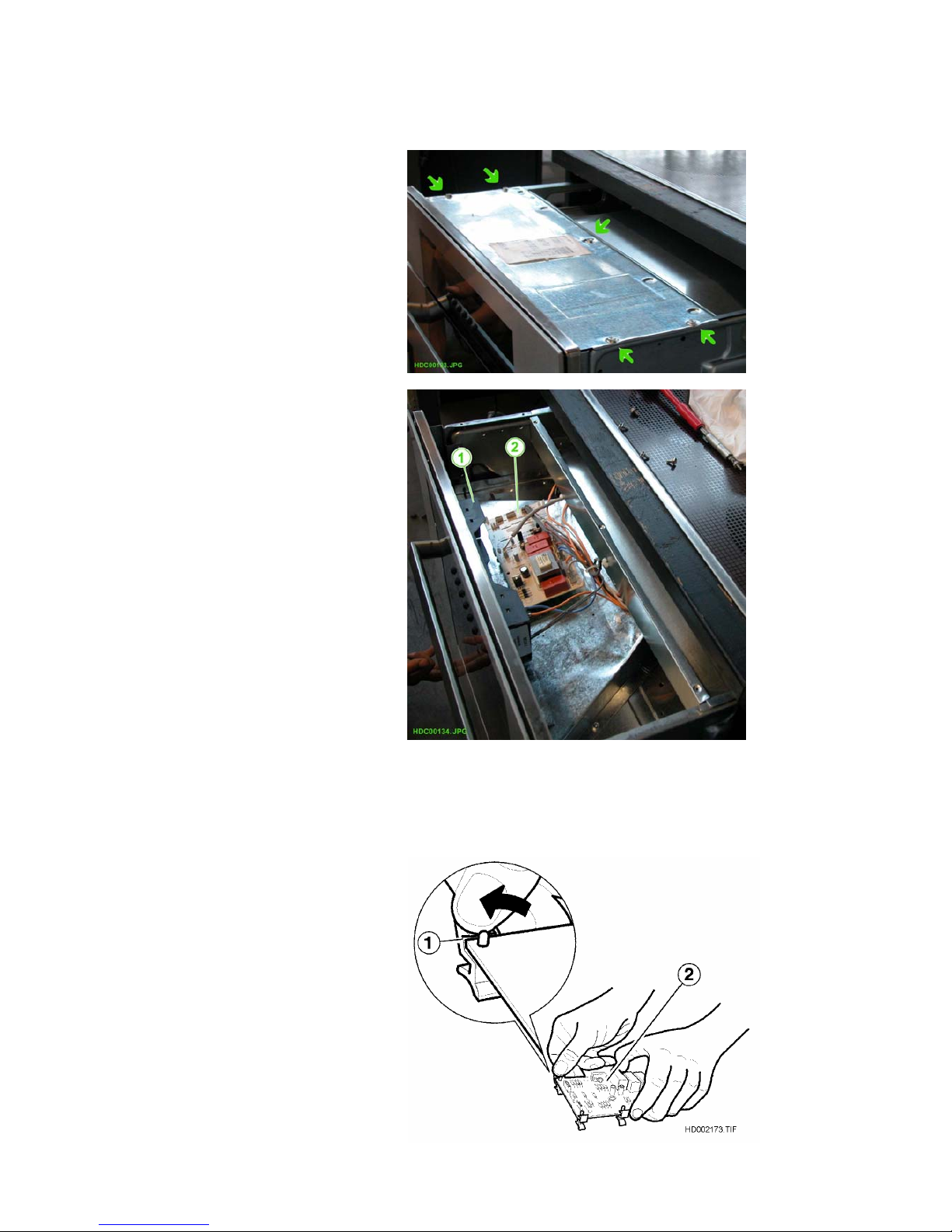
ELECTRONIC VERSION
1. Remove the screws which secure the smaller upper panel
Fig. 17
Screws securing the smaller
upper panel
Fig. 18
1 - KRONOS CONTROL UNIT
2 - POWER BOARD
Proceed as follows to remove a circuit board:
1 - Detach the wires (noting the position of each).
2 - Detach the circuit board from the elastic plastic tabs (see pic. 19)
3 - Remove the circuit board
Fig. 19
1 - PLASTIC ANCHOR TABS
SECURING THE CIRCUIT
BOARDS
2 - KRONOS POWER BOARD
SOI 04.04 FV 14/50 599 35 96-40
2.6.2. UPPER PANEL (FAN AND SAFETY THERMOSTAT)
In both types of oven (electromechanical and electronic), removal of the upper panel provides
access to the tangential cooling fan and the safety thermostat. Proceed as follows to remove
one of the components.
1. Remove the screws which secure the upper panel in position.
2. Detach the connector wires from the tangential cooling fan (or thermostat).
3. Remove the screws which secure the fan (or thermostat) in position.
4. Remove the component
ELECTROMECHANICAL VERSION
Fig. 20
1. FUNCTION SELECTOR
2. END-OF-COOKING TIMER
3. OVEN THERMOSTAT
4. SAFETY THERMOSTAT
4. SAFETY THERMOSTAT
5 - THERMOSTAT ANCHOR
SCREWS
6 - COOLING FAN ANCHOR
SCREWS
7 - COOLING FAN
ELECTRONIC VERSION
Fig. 21
1. GRILL RELAY BOARD
2. CONTROL UNIT BOARD
3. POWER BOARD
4. SAFETY THERMOSTAT
5. THERMOSTAT ANCHOR
SCREWS
6. COOLING FAN ANCHOR
SCREWS
7. COOLING FAN
SOI 04.04 FV 15/50 599 35 96-40
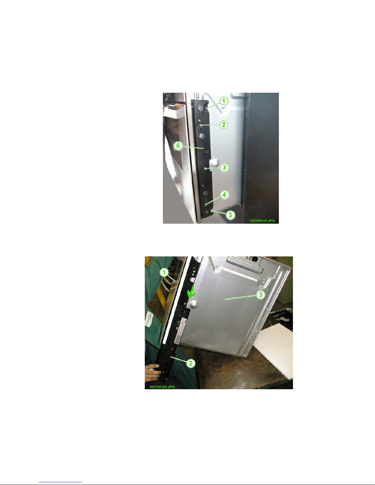
2.7. REMOVING THE LATERAL UPRIGHTS FOR THE FRONT PANEL
- Pull the oven out of the cabinet.
1. Remove the screws which secure the lateral uprights.
2. Tilt the oven towards the rear.
3. Slide the lateral uprights from the lower section of the oven
Fig. 22
1-5. ANCHOR SCREWS
6 - LATERAL UPRIGHT
(Refer to Fig. 46 on page
26 for details of all the
screws fitted to the sides)
Fig. 23
1 - OVEN DOOR
2 - LATERAL UPRIGHT
3 - OVEN SIDE PANEL
 Loading...