

bib`qoliru=eljb=molar`qp=kloqe=^jbof`^
SERVICE MANUAL
BEVERAGE CENTER II
®
5995451233
®
White-Westinghouse
®
OCTOBER 2005
®

TABLE OF CONTENTS
SAFE SERVICING PRACTICES .................................................................................5
INSTALLATION INSTRUCTIONS
Important Safety Instructions ................................................................................................................ 6
Electrical Information ........................................................................................................................ 6
Installation .......................................................................................................................................... 7
Leveling ............................................................................................................................................ 7
To Adjust Front Leveling Screw ..................................................................................................7
Installation Water Line ......................................................................................................................... 8
Door Removal and Reversal Instructions ........................................................................................... 9
To Remove Freezer Door ............................................................................................................ 9
To Remove Refrigerator Door ...................................................................................................... 9
To Remove Center Hinge ............................................................................................................ 9
To Remove Lower Hinge ............................................................................................................. 9
To Reverse Freezer and Refrigerator Door Stops ........................................................................ 9
To Install Lower Hinge On Opposite Side .................................................................................... 9
To Install Center Hinge On Opposite Side ................................................................................... 9
To Install Refrigerator Door ......................................................................................................... 9
To Install Freezer Door ............................................................................................................... 9
FEATURES AT A GLANCE
Cool Down Period ............................................................................................................................. 10
Beverage Center Controls ................................................................................................................. 10
Temperature Control ................................................................................................................... 10
Air Flow Control .......................................................................................................................... 10
Temperature Settings and Adjustment .............................................................................................. 10
FIRST STEPS
Parts ............................................................................................................................................ 11
Beverage Dlivery Kit Box ................................................................................................................... 11
Faucet Assembly Installation ............................................................................................................ 12
Sump and Drip Tray Installation ........................................................................................................ 12
Sump Valve Installation ..................................................................................................................... 12
Regulator Installation ........................................................................................................................ 12
Braided Hose to Regulator Connections ............................................................................................ 13
Braided Hose to Coupler Connection ................................................................................................ 13
Clear Hose to Coupler Connection .................................................................................................... 13
Clear Hose to Door Panel Connection ............................................................................................... 13
Clear Hose to Keg Instullation ........................................................................................................... 13
Delivery Hose Pressurization ............................................................................................................ 14
CO2 Canister to Cabinet Installation .................................................................................................. 14
Keg to Cabinet Installation ................................................................................................................ 14
Tips on Installing the Keg to the Cabinet ........................................................................................... 14
Delivery Hose Arrangment ................................................................................................................. 15
Operating the Beverage Center ......................................................................................................... 15
How to Replace Empty CO2 ............................................................................................................................................ 15
Helpeful Hints ................................................................................................................................... 16
Beer Storage Temperature ................................................................................................................ 16
Recommended Keg Handling ............................................................................................................ 16
BEVERAGE COOLER EXTRA FEATURES
Optional Caster Kit ........................................................................................................................... 16
Optional Ice Maker Kit ...................................................................................................................... 17
NORMAL OPERATING SOUNDS & SIGHTS
Understanding the Sounds You May Hear ........................................................................................ 18
1

CARE & CLEANING
Care & Cleaning Chart ...................................................................................................................... 19
Proper Cleaning of Beverage Center Dispensing System .................................................................. 20
WARRANTY INFORMATION
Beverage Center Warranty ................................................................................................................ 21
TROUBLESHOOTING GUIDE
Beverage Center Operation ............................................................................................................... 22
Sound and Noise .............................................................................................................................. 22
Water / Moisture / Frost Inside Beverage Center ............................................................................... 23
Odor in Beverage Center ................................................................................................................... 23
Door Problems .................................................................................................................................. 23
Common Draft Problems ................................................................................................................... 23
ELECTRICAL COMPONENTS
Electrical Grounding ......................................................................................................................... 24
Compressor Electrical Components and Circuits .............................................................................. 24
Solid State Relay ....................................................................................................................... 24
To Check/Replace Relay ...................................................................................................... 24
Overload Protector ...................................................................................................................... 24
To Check/Replace Overload Protector .................................................................................. 25
Run Capacitor ............................................................................................................................ 25
To Check/Replace Run Capacitor ........................................................................................ 25
Compressor Start Circuit ............................................................................................................ 25
Compressor Run Circuit ............................................................................................................. 25
Compressor Operating Characteristics .............................................................................................. 26
Compressor Electrical Check ........................................................................................................... 26
Control Thermostat ........................................................................................................................... 26
Automatic Defrost Models .......................................................................................................... 26
Temperature Control Mounting .................................................................................................... 26
To Remove Temperature Control . ................................................................................................ 26
To Remove Refrigerator Light Socket ................................................................................................ 27
To Remove Freezer Light Socket ...................................................................................................... 27
Light Switch ...................................................................................................................................... 27
Damper Control ................................................................................................................................. 27
Perimeter Hot Tube ........................................................................................................................... 27
Evaporator Fan and Motor Assembly ................................................................................................ 27
To Remove Freezer Fan Motor ................................................................................................... 27-28
Defrost Timer .................................................................................................................................... 29
To Remove Defrost Timer ........................................................................................................... 29
To Check Defrost Timer .............................................................................................................. 29
Defrost Thermostat ........................................................................................................................... 29
To Remove Defrost Thermostat ................................................................................................... 29
To Test Defrost Thermostat ........................................................................................................ 29
Defrost Heater .................................................................................................................................. 29
To Remove Defrost Heater ........ .................................................................................................. 29-30
Service Data Sheet ........................................................................................................................... 31
Ladder Schematic ............................................................................................................................. 32
Wiring Diagram ................................................................................................................................. 33
AIR CIRCULATION
Automatic Defrost Models ................................................................................................................. 34
Principles of Automatic Defrost Operation .................................................................................. 34
Air Circulation Patterns .............................................................................................................. 34
REFRIGERATION SYSTEM
Definitions ......................................................................................................................................... 35
2

Recovery .................................................................................................................................... 35
Recycling ................................................................................................................................... 35
Reclaim ...................................................................................................................................... 35
Safety Warnings ............................................................................................................................... 35
Compressor Testing ................................................................................................................... 35
Charging Sealed Systems .......................................................................................................... 36
Soldering .......................................................................................................................................... 36
Basic Components ........................................................................................................................... 36
Perimeter Hot Tube ........................................................................................................................... 36
Refrigerant Cycle .............................................................................................................................. 36
Low or Low-Side Leak or Undercharge .............................................................................................. 35-37
Testing For Refrigerant Leaks ........................................................................................................... 37
Checking For Internal (Hot Tube) Leaks ............................................................................................ 37
Compressor Replacement ................................................................................................................. 37
To Flush The System ................................................................................................................. 37
To Use Dry Nitrogen To Flush The System .......................................................................... 38-38
To Use Refrigerant To Flush The System ............................................................................. 38
Installing A New Compressor ...................................................................................................... 38-38
Evaporator Replacement ................................................................................................................... 40-41
Heat Exchanger Replacement .......................................................................................................... 41-42
Perimeter Hot Tube Repair Kit .......................................................................................................... 42-43
Bypassing Perimeter Hot Tube - Step 1 ..................................................................................... 43
Installing The Heater Wire - Step 2 .............................................................................................43
Installing The Heater Wire - Step 3 .............................................................................................43
Condenser Replacement ................................................................................................................... 43-44
Suction Line And Capillary Tube Replacement .................................................................................. 44
Filter-Drier Installation ....................................................................................................................... 44
Evacuating And Recharging .............................................................................................................. 44
Equipment Needed ..................................................................................................................... 44
Installing Evacuation And Recharging Equipment ....................................................................... 45
Evacuating System .................................................................................................................... 45
Charging The System ................................................................................................................. 45-46
Final Leak Test ................................................................................................................................. 46
R-134a Service Information ................................................................................................................. 47
Verify Refrigerant Type In The System .............................................................................................. 47
Dedicated Equipment ................................................................................................................. 47
R-134a Refrigeration Systems .......................................................................................................... 47
Miscibility Of R-134a And Ester Oil ................................................................................................... 47
Water In The Refrigeration System ................................................................................................... 48
Vacuum Chart .................................................................................................................................. 48
Vacuum Pump Maintenance ............................................................................................................. 48
Refrigerant Leaks .............................................................................................................................. 48
Leak Detection ................................................................................................................................. 49
R-134a Properties ............................................................................................................................. 49
HFC-134a, CFC-12 Pressure Temperature Chart ............................................................................... 50
R-134a Health And Safety Information ................................................................................................ 51
Inhalation Toxicity ............................................................................................................................. 51
Cardiac Sensitization ........................................................................................................................ 51
Spills Or Leaks ................................................................................................................................. 51
Skin And Eye Contact ...................................................................................................................... 51
Combustibility Of HFC-134a .............................................................................................................. 52
Leak Testing .............................................................................................................................. 52
Bulk Delivery And Storage .......................................................................................................... 52
Filling And Charging Operations .................................................................................................52
Refrigerant Recovery Systems ................................................................................................... 52
Thermal Decomposition .................................................................................................................... 52
3

ICE MAKER
Ice Maker For Top Mount Models...................................................................................................... 53
Front Cover ....................................................................................................................................... 53
Ice Maker Components ..................................................................................................................... 53
Ice Mold ..................................................................................................................................... 53
Mold Heater ................................................................................................................................ 53
Ice Stripper ................................................................................................................................. 53
Ice Ejector .................................................................................................................................. 53
Water Valve Assembly ............................................................................................................... 53
Thermostat ................................................................................................................................. 54
Sensing Arm & Linkage .............................................................................................................. 54
Timing Switches ......................................................................................................................... 54
TCO - Thermal Cut-Out ............................................................................................................... 54
Timing Cam & Coupler ............................................................................................................... 54
Timing Gear ................................................................................................................................54
Motor ......................................................................................................................................... 54
Fill Trough .................................................................................................................................. 54
Wiring ........................................................................................................................................ 54
Installing Water Supply Line To Ice Maker ........................................................................................ 55
Test Cycling Ice Maker ............................................................................................................... 55
Water Valve Switch - Water Fill Volume ..................................................................................... 55
Parts Replacement ..................................................................................................................... 55
To Replace Front Cover ........................................................................................................ 55
To Replace Fill Trough & Bearings ....................................................................................... 56
To Replace Ice Stripper ........................................................................................................ 56
To Replace Ejector Blades ................................................................................................... 56
To Replace Motor & Switch Mounting Plate ......................................................................... 56
To Replace Motor ................................................................................................................. 56
To Replace Water Fill Switch ............................................................................................... 56
To Replace Hold Switch ....................................................................................................... 57
To Replace Ice Maker Control Shut-Off Switch ..................................................................... 57
To Replace Ice Maker Thermostat ........................................................................................ 57
To Replace TCO ..................................................................................................................57
To Replace Mold Heater ....................................................................................................... 58
Fault Diagnosis ................................................................................................................................. 58
Complaint - Ice Maker Fails To Start .......................................................................................... 58
Complaint - Ice Maker Fails To Complete Cycle ......................................................................... 58
Complaint - Ice Maker Fails To Stop At End Of Cycle ................................................................ 58
Complaint - Ice Maker Continues To Eject When Container Is Full ............................................. 58
Complaint - Ice Maker Produces Undersized Ice Pieces ............................................................. 58
Ice Maker Testing Procedures .......................................................................................................... 59
Operating Cycle ......................................................................................................................... 59
Operating Cycle Illustrations - Manual Cycle .............................................................................. 59
Operating Cycle Illustrations - Electrical ..................................................................................... 59-66
Operating Cycle Illustrations - Mechanical .................................................................................. 66-68
Ice Maker - Exploded View ............................................................................................................... 69
Ice Maker Wiring Diagrams - Enlarged View ..................................................................................... 70
Ice Maker Installation Instructions ....................................................................... 71
4
SAFE SERVICING PRACTICES - ALL APPLIANCES
To avoid personal injury and/or property damage, it is important that Safe Servicing
Practices be observed. The following are some limited examples of safe practices:
1. DO NOT attempt a product repair if you doubt your ability to complete it in a safe
and satisfactory manner.
2. Before servicing or moving an appliance:
• Remove power cord from the electrical outlet, trip circuit breaker to the OFF
position, or remove fuse
• Turn off gas supply
• Turn off water supply
3. Never interfere with the proper operation of any safety device.
4. Use The Correct Replacement Parts Cataloged For This Appliance.
Substitutions May Defeat Compliance With Safety Standards Set For
Home Appliances.
5. GROUNDING: The standard color code for safety ground wires is GREEN, or
GREEN with YELLOW STRIPES. DO NOT use ground leads as current carrying
conductors. It is EXTREMELY important that the service technician reestablish
all safety grounds prior to completion of service. Failure to do so will create a
hazard.
6. Prior to returning the product to service, ensure that:
• All electrical connections are correct and secure
• All electrical leads are properly dressed and secured away from sharp
edges, high-temperature components, and moving parts
• All non-insulated electrical terminals, connectors, heaters, etc. are adequately
spaced away from all metal parts and panels
• All safety grounds (both internal and external) are correctly and securely
connected
• All panels are properly and securely reassembled
WARNING
This service manual is intended for use by persons having electrical and mechnical training and
a level of knowledge of these subjects generally considered acceptable in the appliance repair
trade. Frigidaire Home Products cannot be responsible, nor assume any liability, for injury or
damage of any kind arising from the use of this manual.
© 2005 Electrolux Home Products, Inc.
5
IMPORTANT SAFETY INSTRUCTIONS
WARNING WARNING
WARNING
WARNING WARNING
Please Read All Instructions Before Using or Servicing This
beverage center.
FOR YOUR SAFETY
• Do not store or use gasoline, or other flammable liquids
in the vicinity of this or any other appliance. Read product
labels for warnings regarding flammability and other
hazards.
• Do not operate the beverage center in the presense of
explosive fumes.
• Avoid contact with any moving parts of the automatic ice
maker. (some models)
CHILD SAFETY
Destroy or recycle the carton, plastic bags, and any exterior
wrapping material immediately after this beverage center is
unpacked. Children should NEVER use these items to play
with. Cartons covered with rugs, bedspreads, plastic sheets or
stretch wrap may become airtight chambers, and can quickly
cause suffocation.
WARNING WARNING
WARNING
WARNING WARNING
These guidelines must be followed to ensure that safety
mechanisms in this beverage center will operate properly.
ELECTRICAL INFORMATION
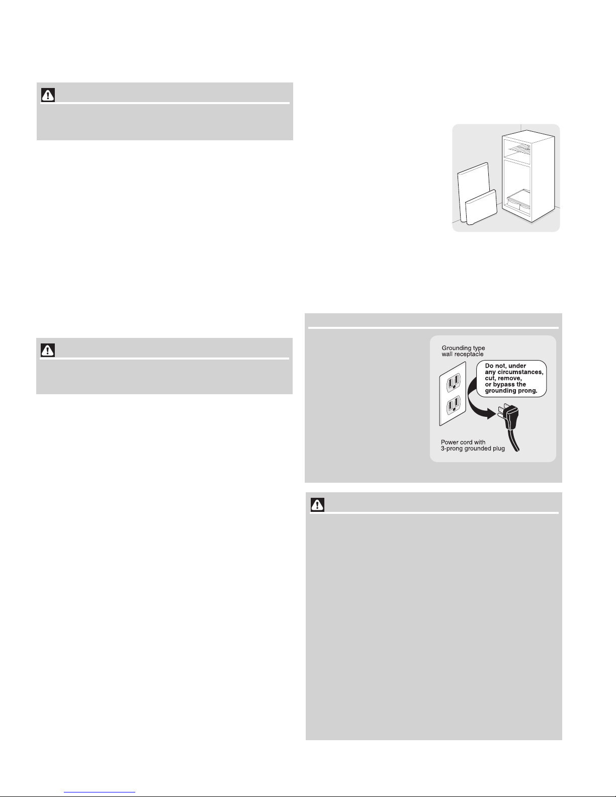
• The beverage center must be plugged into its own
dedicated 115 Volt, 60 Hz., AC only electric outlet. The
power cord of the appliance is equipped with a threeprong grounding plug for your protection against electrical
shock hazards. It must be plugged directly into a properly
grounded three-prong receptacle. The receptacle must be
installed in accordance with local codes and ordinances.
Consult a qualified electrician. Do not use an extension
cord or adapter plug.
• If the power cord is damaged, it should be replaced by the
manufacturer, service technician or a qualified person to
prevent any risk.
• Never unplug this beverage center by pulling on the
power cord. Always grip the plug firmly, and pull straight
out from the receptacle to prevent damaging the power
cord.
• Unplug this beverage center before cleaning and before
replacing a light bulb to avoid electrical shock.
• Performance may be affected if the voltage varies by 10%
or more. Operating this beverage center with insufficient
power can damage the compressor. Such damage is not
covered under your warranty.
• Do not plug the unit into an outlet controlled by a wall
switch or pull cord to prevent this beverage center from
being turned off accidentally.
• Avoid connecting this beverage center to a Ground Fault
Interruptor (GFI) circuit.
PROPER DISPOSAL OF YOUR BEVERAGE CENTER
Risk of child entrapment
Child entrapment and suffocation
are not problems of the past. Junked
or abandoned refrigerators or
freezers are still dangerous – even if
they will sit for “just a few days.” If
you are getting rid of your old
refrigerator or freezer, please follow
the instructions below to help
prevent accidents.
Before you throw away your old
refrigerator/ freezer:
• Remove doors.
• Leave shelves in place so children may not easily climb
inside.
• Have refrigerant removed by a qualified service
technician.
IMPORIMPOR
IMPOR
IMPORIMPOR
Turning the Air Flow and
Temperature Controls to “0”
turns off the compressor
and prevents your
Beverage Center from
cooling, but does not
disconnect the power to the
light bulb and other
electrical components. To
turn off power to your
Beverage Center you must
unplug the power cord from
the wall outlet.
•CO2 canisters must be handled with extreme care. They
• ALWAYS connect CO2 gas canisters to a pressure
• NEVER drop or throw the CO2 canister.
• NEVER connect gas canister directly to keg.
• ALWAYS keep CO
• In case of CO2 leakage, ventilate and evacuate the area
• ALWAYS keep canister secured in an upright position.
• Check the Department of Transportation (D.O.T.) test
• Return outdated canister to your gas supplier for one
TT
ANTANT
T
ANT
TT
ANTANT
WARNING WARNING
WARNING
WARNING WARNING
CO2 CANISTER SAFE HANDLING
contain potentially hazardous high pressure
compressed gas.
regulator.
canisters in a cool place (70º or less)
and away from heat.
immediately.
date on the canister neck and do not use if older than 5
years.
that is within the time limit.
2
6
INSTALLATION
This Service Manual provides specific operating instructions for your
model. The customer should use this beverage center only as
instructed in the Use & Care Manual. Before starting this beverage
center, follow these important first steps.
LOCATION
• Choose a place that is near a grounded electrical outlet.
Do Not use an extension cord or an adapter plug.
• If possible, place this beverage center out of direct
sunlight and away from the range, dishwasher or other
heat sources.
• This beverage center must be installed on a floor that is
level and strong enough to support a fully loaded
beverage center.
• Consider water supply availability for models equipped
with an automatic ice maker.
CAUTION CAUTION
CAUTION
CAUTION CAUTION
• Do Not install the beverage center where the
temperature will drop below 55°F (13°C) or rise above
110°F (43°C). The compressor will not be able to
maintain proper temperatures inside the beverage
center.
• DO NOT block the toe grille on the lower front of your
beverage center. Sufficient air circulation is essential
for the proper operation of your beverage center.
• THIS BEVERAGE CENTER IS NOT INTENDED FOR
OUTDOOR USE.
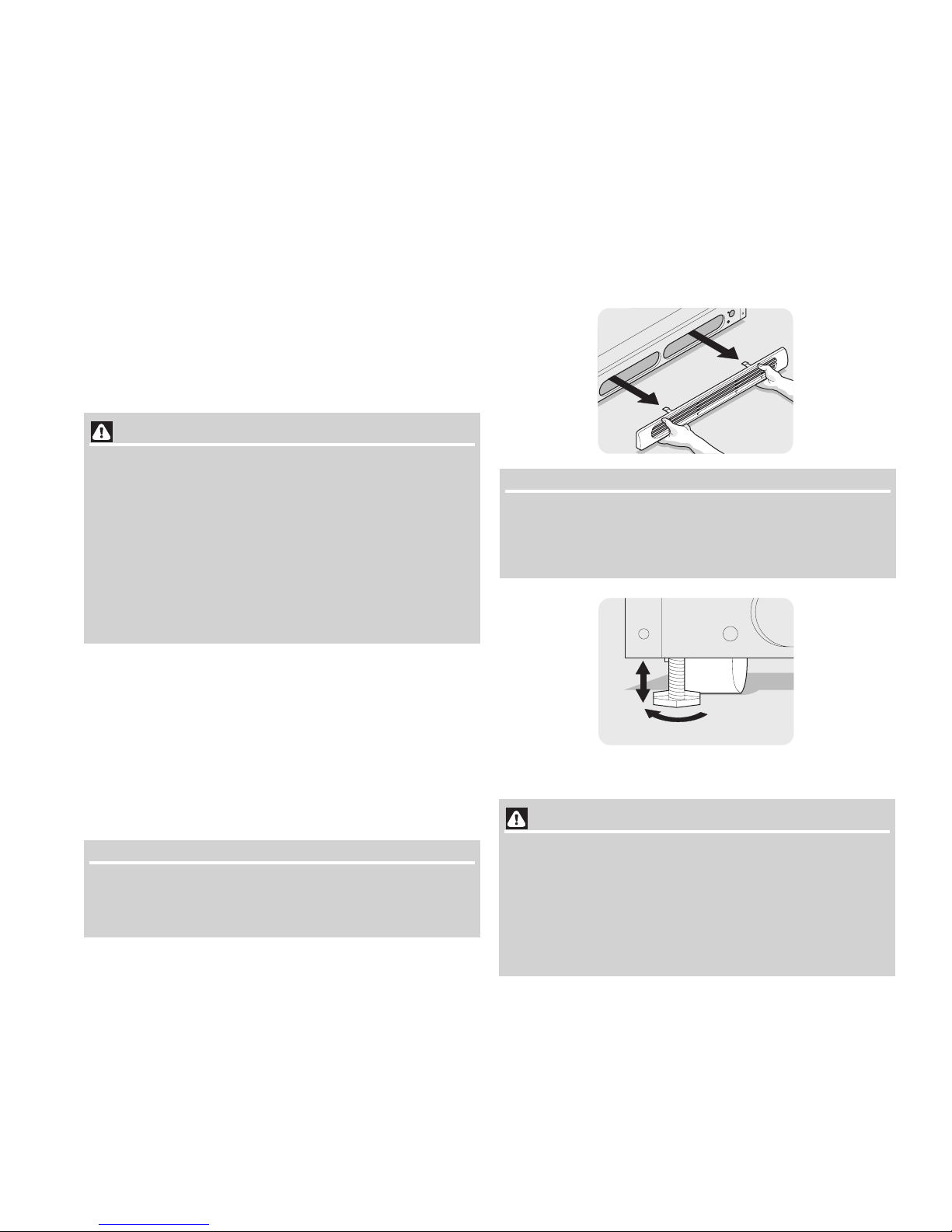
LEVELING
All four corners of the beverage center must rest firmly on a solid
floor. The beverage center is equipped with adjustable leveling screws
to help level your unit.
To Level Your
Beverage Center:
1. Remove toe grille.
2. Use adjustable wrench to adjust leveling screws.
NOTENOTE
NOTE
NOTENOTE
Raise the front of the beverage center enough so the doors
close freely when opened halfway. The beverage center
should slope ¼” to ½” from front to back. Then level the
beverage center from side to side.
INSTALLATION
Installation Clearances
• Allow the following clearances for ease of installation,
proper air circulation, and plumbing and electrical
connections:
Sides & Top 3/8”
Back 1”
DOOR OPENING
NOTENOTE
NOTE
NOTENOTE
If the beverage center is placed with the door hinge side against a
wall, you may have to allow additional space so the door can be
opened wider.
The beverage center should be positioned to allow easy access to a
counter when removing food. To make this possible, the direction in
which the doors open can be reversed. See
Instructions
.
Door Removal & Reversal
Raise
Stationary Front Roller
with Leveling Screw
CACA
UTIONUTION
CA
UTION
CACA
UTIONUTION
DO NOT ATTEMPT TO MOVE OR RELOCATE
THE BEVERAGE CENTER WITH A KEG
INSIDE. THE TWO FRONT LEVELING
SCREWS MUST BE RAISED BEFORE YOU
MOVE THE REFRIGERATOR TO PREVENT
FLOOR DAMAGE.
7
INSTALLATION - CONNECTING ICE MAKER TO WATER SUPPLY
WARNING WARNING
WARNING
WARNING WARNING
To avoid electric shock, which can cause death or severe
personal injury, disconnect the beverage center from
electrical power before connecting a water supply line to
the beverage center. or before servicing the beverage center.
CAUTION CAUTION
CAUTION
CAUTION CAUTION
To Avoid Property Damage:
• Copper tubing is recommended for the water supply
line. Water supply tubing made of ¼” plastic is not
recommended since it greatly increases the potential
for water leaks. Manufacturer will not be responsible
for any damage if plastic tubing is used for supply
line.
• DO NOT install water supply tubing in areas where
temperatures fall below freezing.
• Chemicals from a malfunctioning softener can
damage the ice maker. If the ice maker is connected
to soft water, ensure that the softener is maintained
and working properly.
IMPORIMPOR
IMPOR
IMPORIMPOR
TT
ANTANT
T
ANT
TT
ANTANT
To Connect Water Supply Line To Ice Maker Inlet Valve
1. Disconnect beverage center from electric power source.
2. Place end of water supply line into sink or bucket. Turn ON
water supply and flush supply line until water is clear. Turn
OFF water supply at shutoff valve.
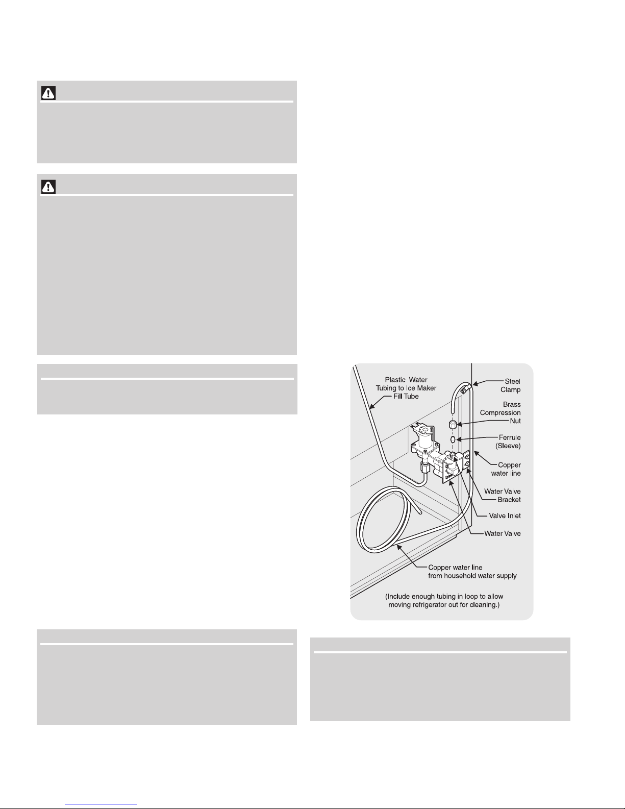
3. Unscrew plastic cap from water valve inlet and discard
cap.
4. Slide brass compression nut, then ferrule (sleeve) onto
water supply line, as shown.
5. Push water supply line into water valve inlet as far as it
will go (¼ inch). Slide ferrule (sleeve) into valve inlet and
finger tighten compression nut onto valve. Tighten another
half turn with a wrench; DO NOT over tighten.
6. With steel clamp and screw, secure water supply line to
rear panel of beverage center as shown.
7. Coil excess water supply line (about 2½ turns) behind
beverage center as shown and arrange coils so they do
not vibrate or wear against any other surface.
8. Turn ON water supply at shutoff valve and tighten any
connections that leak.
9. Reconnect beverage center to electrical power source.
10. To turn ice maker on, lower wire signal arm (see ice
maker front cover for ON/OFF position of arm).
Ensure that your water supply line connections comply with
all local plumbing codes.
Before Installing The Water Supply Line, You Will Need
• Basic Tools: adjustable wrench, flat-blade screwdriver,
and PhillipsTM screwdriver
• Access to a household cold water line with water pressure
between 30 and 100 psi.
• A water supply line made of ¼ inch (6.4 mm) OD, copper
tubing. To determine the length of copper tubing needed,
you will need to measure the distance from the ice maker
inlet valve at the back of the beverage center to your cold
water pipe. Then add approximately 7 feet (2.1 meters), so
the beverage center can be moved out for cleaning (as
shown).
• A shutoff valve to connect the water supply line to your
household water system. DO NOT use a self-piercing type
shutoff valve.
• A compression nut and ferrule (sleeve) for connecting the
water supply line to the ice maker inlet valve.
NOTENOTE
NOTE
NOTENOTE
Water line kit number 5303917950, available from your appliance
dealer or part distributor, contains 25 feet (7.6 meters) of ¼ inch OD
copper tubing, a saddle type shut off valve (nonpiercing), (2) ¼ inch
brass compression nuts, (2) ferrules/sleeves, and instructions for
installing a water supply line.
IMPORIMPOR
IMPOR
IMPORIMPOR
It takes approximately 24 hours for the ice maker to begin
producing ice. Air in new plumbing lines may cause ice
maker to cycle two or three times before making a full tray of
ice. New plumbing may cause ice to be discolored or have
poor flavor. Discard ice made during the first 24 hours.
TT
ANTANT
T
ANT
TT
ANTANT
8

Door Stop
Hinge
Hole Plug
Cabinet
Hole Plugs
Shim
Hinge Pin
Washer
Center
Hinge
Screws
Door
Stop
Door Stop
Screw
Hinge
Hole Plug
Handle
Hole Plugs
Screw
Top
Hinge
Screw
Center
Hinge
Screw
DOOR REMOVAL / REVERSAL INSTRUCTIONS
Bottom
Hinge
Screw
DOOR REMOVAL AND REVERSAL INSTRUCTIONS:
NOTENOTE
NOTE
NOTENOTE
Screws
Top Hinge
The direction in which your beverage center doors open (door swing) can be
reversed, from left to right or right to left, by moving the door hinges from one
side to the other. Reversing the door swing should be performed by a
qualified person.
IMPORIMPOR
IMPOR
IMPORIMPOR
TT
ANTANT
T
ANT
TT
ANTANT
Before you begin, turn the beverage center temperature control to “0” and
remove the electrical power cord from the wall outlet. Remove any food from
door shelves.
1. Remove toe grille.
2. Remove top hinge with 3/8” hex driver and lift freezer door off of center
hinge pin. Set door aside.
3. Unscrew center hinge pin using adjustable wrench and save for
reassembly. Ensure plastic washer stays on hinge pin.
4. Lift refrigerator door off of bottom hinge and set aside.
5. Remove center hinge and shim by removing inside screw and
loosening two outside screws enough to allow hinge and shim to slide out.
Tighten screws.
6. Loosen two outside screws on opposite side of refrigerator, remove inside
screw and install center hinge.
7. Remove two screws on bottom hinge with 3/8” socket wrench.
8. Install bottom hinge on opposite side with the two screws removed from
step 7.
9. Unscrew bottom hinge pin using adjustable wrench. Move hinge pin to
other hole in hinge and tighten with adjustable wrench.
10. Move beverage center door stops to opposite side. Before starting screws,
use an awl to puncture the foam.
11. Position beverage center door onto bottom hinge pin and screw center
hinge pin through center hinge into top of door. Close beverage center
door to help align hinge hole.
12. Tighten center hinge pin with adjustable wrench.
13. Remove cabinet and hinge hole plugs and move to opposite side.
14. Lower freezer door onto center hinge pin.
15. Close freezer door. Have an assistant lift up on opposite side of door while
tightening screws to install top hinge.
16. Replace toe grille.
17. Plug in electrical power cord and turn beverage center temperature
control to the “5” position. Adjust setting as necessary.
9
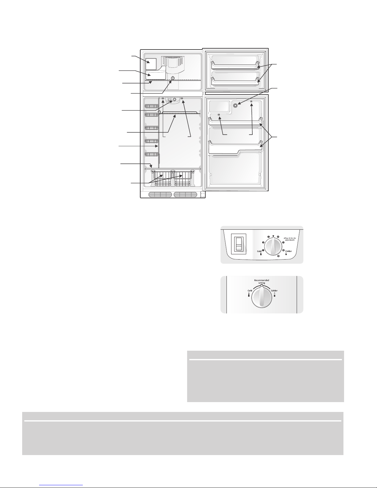
Ice Maker
(Accessory)
Ice Bucket
(Accessory)
FEATURES AT A GLANCE
Door Racks
Freezer Shelf
Air Flow Control
Temperature
Features may vary
Control
according to model
Shelf
Shelf Tower
Keg Support
Shelf
Slide Out
Baskets
TEMPERATURE CONTROLS
COOL DOWN PERIOD
To ensure safe food storage, allow the beverage center to
operate with the doors closed for at least 12 hours before
loading it with food and beverages.
Hose Clips
Hose Clips
Faucet Opening
Door Racks
BEVERAGE CENTER CONTROLS
Temperature Control
This rotary control is the primary control for the refrigerated
compartment temperature. If the beverage center is too warm,
adjust this control in the “Colder” direction. If the beverage
center is too cold, adjust this control in the “Cold” direction.
Temperature Control (some models)
Air Flow Control
This rotary control is the primary control for the freezer
compartment temperature. If the freezer is too warm, adjust this
control in the “Colder” direction. If the freezer is too cold, adjust
this control in the “Cold” direction.
TEMPERATURE SETTING AND ADJUSTMENT
For beer storage, the recommended initial setting is 5. Under
most conditions, this setting will provide for dispensed beer
between 34-38° F. You may adjust as required to suit your
individual taste and the beverage center operating conditions.
After a control adjustment, always allow 24 hours for the
beer to stabilize at the new temperature before making
To maintain temperatures, a fan circulates air in the beverage center
compartments. For good circulation, do not block cold air vents with
food items.
IMPORIMPOR
IMPOR
IMPORIMPOR
Turning the beverage center temperature control to “0” turns
off the compressor, but does not disconnect the power to the
light bulb and other electrical components. To turn off power
to your beverage center, you must unplug the power cord
from the wall outlet.
additional adjustments.
NOTENOTE
NOTE
NOTENOTE
When purchasing a beer keg, always purchase a keg cold (<38°F), transport as quickly as possible, and get it installed in the
cold beverage center within 2 hours. Under most conditions, these guidelines will allow serving of properly cooled beer within
24 hours. Purchasing a keg at a temperature above 38°F, and/or exposure to elevated temperatures longer than 2 hours will
require additional time for the beer to be cooled to optimum serving temperature.
Air Flow Control (some models)
TT
ANTANT
T
ANT
TT
ANTANT
10
FIRST STEPS
This Service Manual provides specific assembly, operating and
maintenance instructions for the Beverage Center. The beverage center
should only be used as instructed in the Use and Care Manual
provided with the product. Before starting the beverage center,
follow these important first steps.
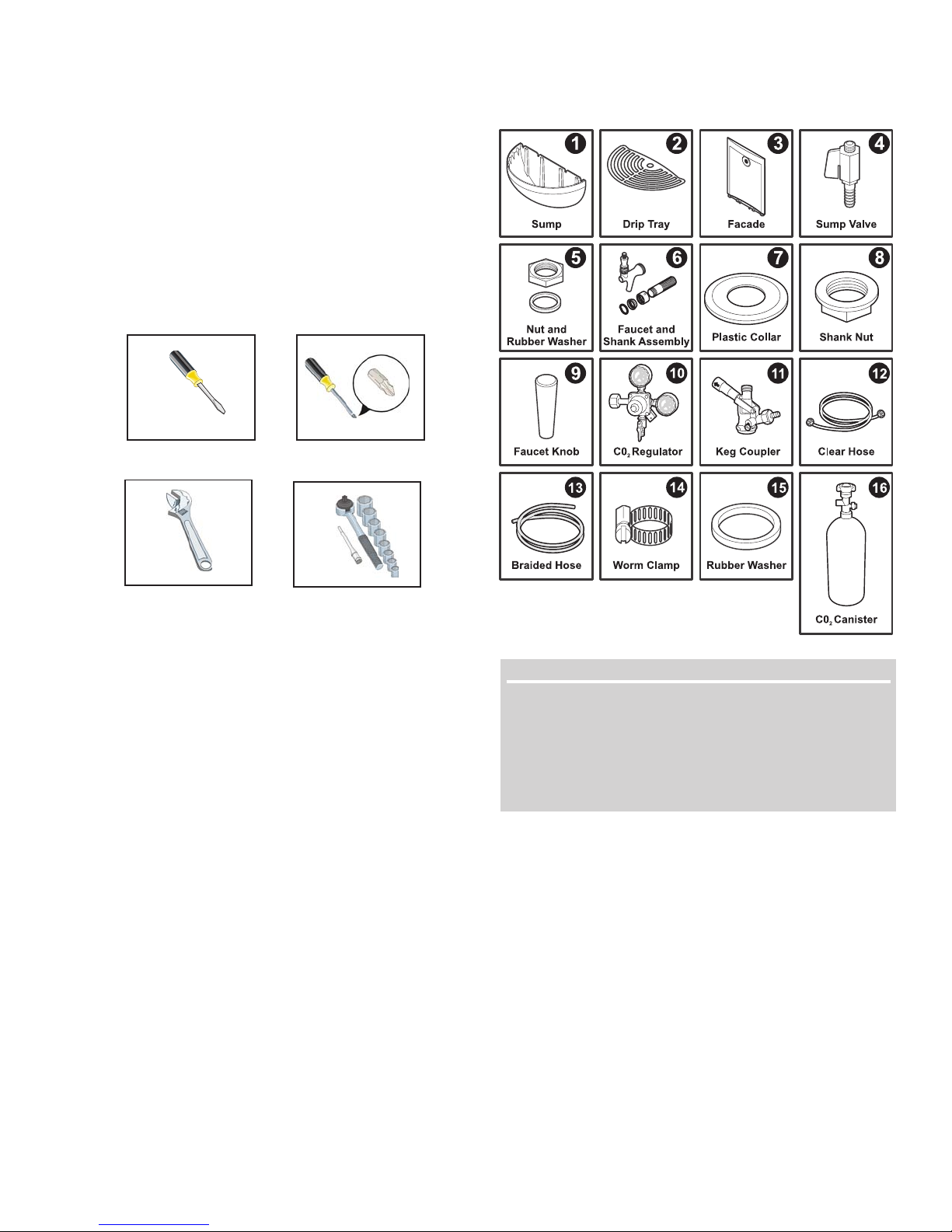
PA RT S
The beverage center comes with a box that contains all the required
parts and accessories. Check to make sure that you have received the
box containing all of the components listed below. You will need the
following tools to assemble the beverage center.
TM
Flat Tip
Screwdriver
Phillips
Screwdriver
Adjustable Wrench
Socket Wrench
BEVERAGE DELIVERY KIT BOX
(1) Sump 1 piece
(2) Drip Tray 1 piece
(3) Facade 1 piece
(4) Sump Valve 1 piece
(5) Nut & Rubber Washer (Black) 2 pieces
(1 nut and 2 washers included with sump valve)
(6) Faucet and Shank Assembly 1 piece
(7) Plastic Collar 1 piece
(8) Shank Nut 1 piece
(9) Faucet Knob 1 piece
(10) CO
(11) Keg Coupler 1 piece
(12) Clear Hose (Delivery Line) 1 piece
(13) Braided Hose (Gas Line) 1 piece
(14) Worm Clamp (Included with Gas Line Hose) 2 pieces
(15) Rubber Washer (Black) 2 pieces
(16) CO
Regulator (with plastic washer) 1 piece
2
(Included with Delivery Line Hose)
Canister (Empty) 1 piece
2
NOTENOTE
NOTE
NOTENOTE
The box comes with a “D System” type Keg Coupler (11).
Depending on your choice of beer, you may require a
different Keg Coupler (11). Check with your local beer
distributor to determine which type system you need, and
order additional Key Couplers as needed. For assistance
call Electrolux Consumer Services at 1-800-944-9044
.
11
FIRST STEPS (continued)
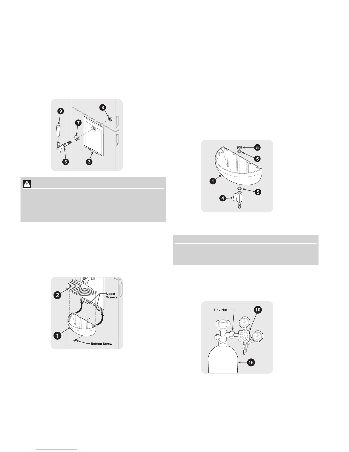
FAUCET ASSEMBLY INSTALLATION
• Attach faucet knob (9) to Faucet & Shank Assembly (6).
• Slip the Faucet & Shank Assembly (6) through the black
plastic collar (7) (flat side toward door), Facade (3), and
hole in door.
• Thread on the large Shank Nut (8) and tighten until snug,
using an adjustable wrench. DO NOT over tighten.
CAUTION CAUTION
CAUTION
CAUTION CAUTION
Replacing the faucet knob (9) with a longer knob is not
recommended. This may interfere with the opening of the
freezer door causing beverage spillage and/or damage to
the faucet assembly and door.
SUMP AND DRIP TRAY ASSEMBLY INSTALLATION
• Remove bottom mounting screw.
• Align the two notched mounting tabs on back of sump (1)
with upper mounting screws in door and push up.
• Install bottom mounting screw through slot and tighten.
SUMP VALVE INSTALLATION
• Place one rubber washer (5) on threaded end of sump
valve (4).
• Slip sump valve with washer through hole in bottom of sump
(1).
• Place remaining rubber washer (5) over threaded end of
sump.
• Thread plastic nut (5) onto threaded end of sump valve and
tighten until snug.
• Make sure knob on valve is located to front for proper
operation.
• Place Drip Tray (2) onto the Sump (1).
REGULATOR INSTALLATION
• Check to ensure plastic washer is inside the hex nut.
NOTENOTE
NOTE
NOTENOTE
If the plastic washer is missing, please call Electrolux Consumer
Services at 1-800-944-9044 or your part distributor for the washer
• Fasten the CO2 regulator (10) to the CO2 canister (16). Place
the regulator to the right of the tank.
• Tighten the hex nut securely. DO NOT over tighten. Over
tightening may damage the gasket in the nut of the regulator.
.
12
FIRST STEPS (continued)
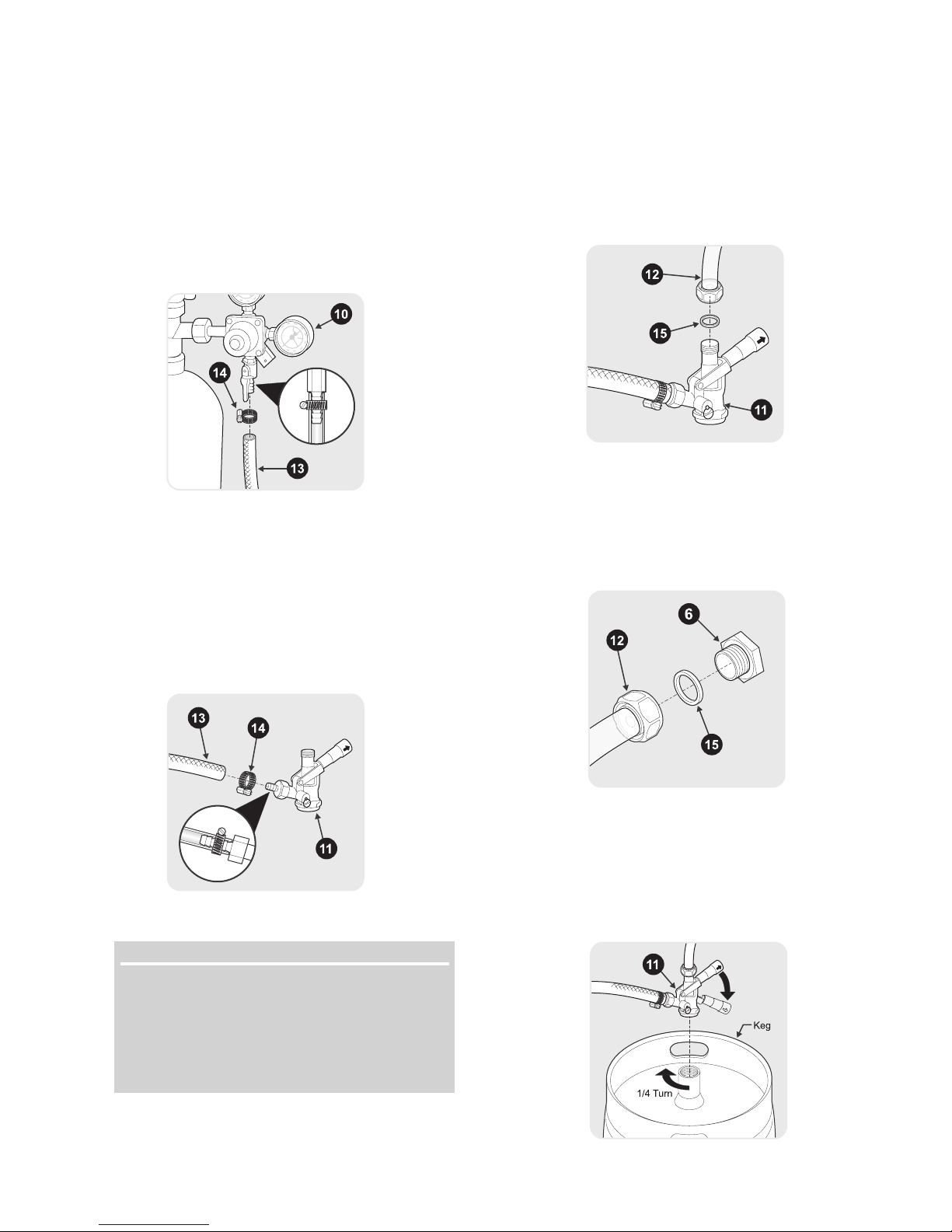
BRAIDED HOSE TO REGULATOR CONNECTION
• Slip one Worm Clamp (14) onto braided hose (13).
• Attach that end of the braided hose (13) to the hose barb of
the CO2 regulator (10). Push hose up until seated against
hex head.
• Secure the braided hose (13) to the CO2 regulator (10) using
the worm clamp (14). Use a flat tip screwdriver to tightly
secure the worm clamp.
BRAIDED HOSE TO COUPLER CONNECTION
• Slip one Worm Clamp (14) onto the other end of the braided
hose (13).
• Push the other end of the braided hose (13) onto the keg
coupler (11) until seated against hex head.
• Secure the hose (13) to the keg coupler (11) using the
remaining worm clamp (14). Use a flat tip screwdriver to
tightly secure the worm clamp to the braided hose to prevent
gas leakage.
CLEAR HOSE TO COUPLER CONNECTION
• Place one of the supplied rubber washer (15) inside the
hex nut on the one end of the clear hose (12) (beverage
delivery line) and attach to keg coupler (11). Be sure to
tighten the nut securely to prevent leakage. DO NOT over
tighten. Over tightening may damage the gasket in the nut.
CLEAR HOSE TO DOOR PANEL CONNECTION
• Place the other supplied rubber washer (15) inside the
hex nut on the other end of the clear hose (12) (beverage
delivery line) and attach to the Faucet & Shank Assembly
(6) protruding through the door panel. Be sure to tighten
the nut securely to prevent leakage. DO NOT over tighten.
Over tightening may damage the gasket in the nut.
NOTENOTE
NOTE
NOTENOTE
Depending on the customers choice of beer, they may
require a different Keg Coupler (11). The customer will
need to check with there local beer distributor to determine
which type system they need, and order additional Keg
Couplers if needed. For assistance the customer can call
Electrolux Consumer Services at 1-800-944-9044
COUPLER TO KEG INSTALLATION
• Align locks on keg coupler (11) with housing on top of keg
and push down on the keg coupler (11).
• Turn the tap head handle clockwise 1/4 turn. The tap head is
now secured to the keg.
• Pull the tap handle out and push down to open the port in
the keg.
.
13
FIRST STEPS (continued)
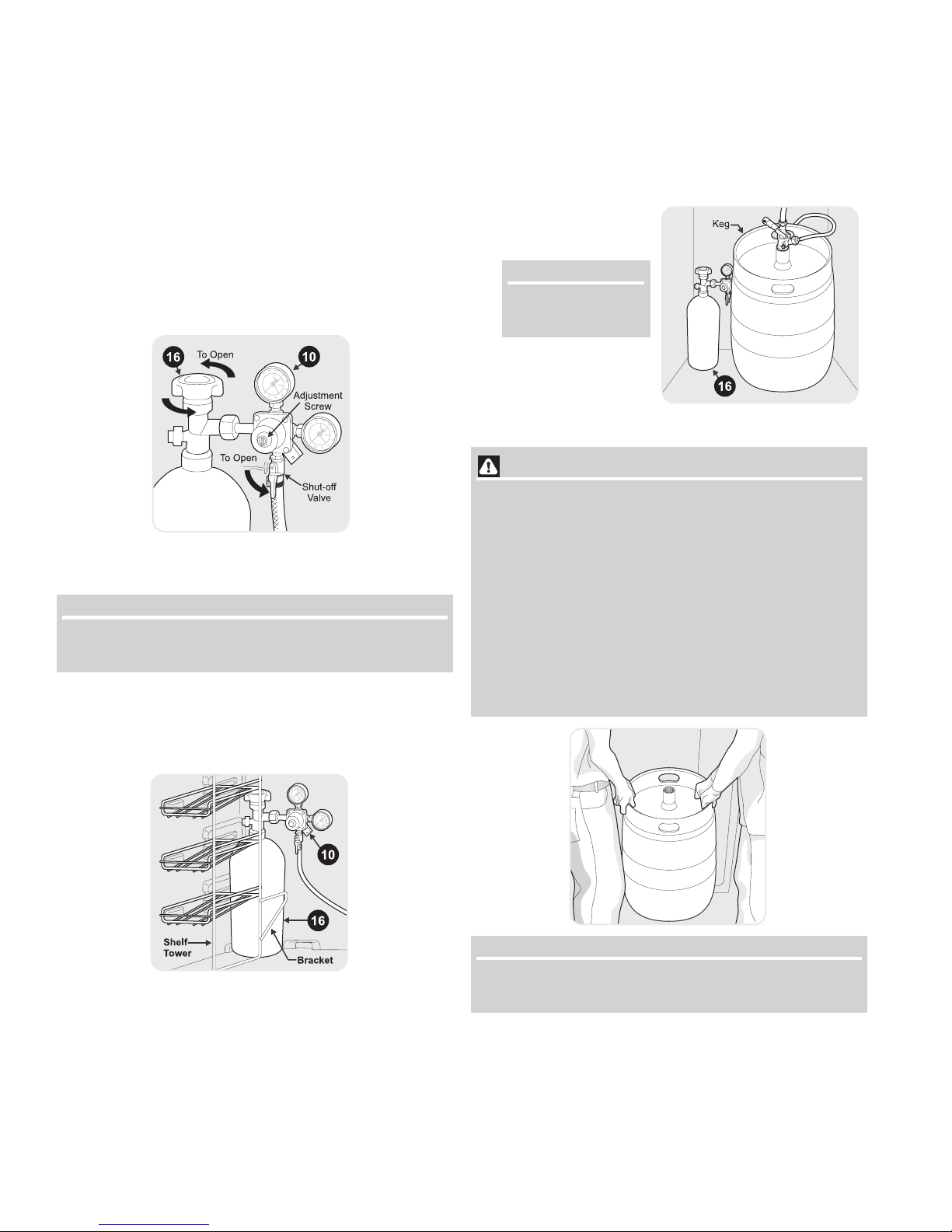
DELIVERY HOSE PRESSURIZATION
• Open the CO2 canister valve all the way by turning
counterclockwise until it stops. This valve seals at both the
fully open and fully closed positions. Failure to completely
open or close the valve could result in premature loss of
pressure.
CO
• Open the regulator shut-off valve by moving it to the 6
• Check gauge pressure. Adjust the Regulator Adjustment
2
o’clock position.
Screw as necessary until the pressure reads between 12
to 14 psi. Tighten the Adjustment Lock Nut.
CO2 CANISTER TO CABINET INSTALLATION
• Remove adjustable shelf from inside of cabinet.
NOTENOTE
NOTE
NOTENOTE
The adjustable shelf is intended for use with 1/4 keg or no
keg. Reinstall shelf after keg installion if using 1/4 keg.
• Lift and place the CO2 canister (16) with the CO2 regulator
(10) behind the shelf tower inside of the CO2 canister bracket.
It is important that the canister be kept in an upright position
to operate efficiently.
KEG TO CABINET INSTALLATION
• Place the keg on the Support Shelf and push back next to
the CO
THE CABINET) inside the cabinet as shown.
canister (16) (See TIPS ON INSTALLING KEG TO
2
NOTENOTE
NOTE
NOTENOTE
Shelf tower has been
removed for clarity.
TIPS ON INSTALLING THE KEG TO THE CABINET
WARNING WARNING
WARNING
WARNING WARNING
SAFE KEG HANDLING
• Installing the keg to the cabinet is a two-person team
effort. NEVER lift a full ½ keg alone. Doing so may cause
severe injury.
• With the door fully open and the help of another person,
lift the keg vertically on both sides until the keg is higher
than the keg support shelf.
• Set the edge of the keg on top of the plastic protective
plate located on top of keg support shelf. Slide the keg
back until it is fully inside the cabinet.
• Care must be taken to avoid damage to the temperature
control and shelf tower located in the cabinet.
NOTENOTE
NOTE
NOTENOTE
The above illustration does not show the tap installed for
clarity of installation.
14
FIRST STEPS (continued)
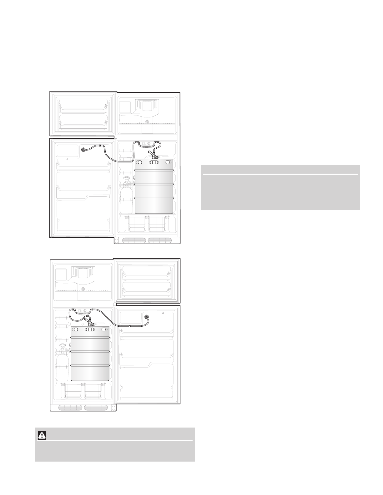
DELIVERY HOSE ARRANGEMENT
• Insert the clear hose (12) (delivery hose) into the hose
routing clips attached to the door and the cabinet. Follow
the hose routing shown below depending on the door
swing direction of your door.
Left Hand Swing
Right Hand Swing
CAUTION CAUTION
CAUTION
CAUTION CAUTION
Failure to route hoses properly may cause the hose to
become kinked or caught in door.
OPERATING THE BEVERAGE CENTER
• Make sure that the beverage center is plugged in properly
to a 115V, 60Hz AC only electrical outlet. Refer to
Electrical Information on page 6.
• Make sure that the drip tray and sump are secured under
the faucet.
• Start with a clean beverage glass that has been wetted in
cold water. Place the glass at a 45º angle, one inch below
the faucet. Do not let the glass touch the faucet. Open the
faucet all the way.
• After the glass has reached half full, gradually bring the
glass to an upright position.
• Let the remaining beverage run straight down the middle.
This insures proper release of CO
1" foam head.
by producing a ¾” to a
2
• Close the faucet completely and quickly.
NOTENOTE
NOTE
NOTENOTE
It is normal to see condensation forming around the faucet.
This condensation is caused by the temperature difference
between the cold beverage and the inner surfaces of the
faucet when beverage is being drawn through the line.
HOW TO REPLACE AN EMPTY CO2 CANISTER
• Remove hoses from routing clips.
• Remove the keg, then remove CO2 canister.
• Close the canister valve of the empty canister by turning
clockwise until it stops.
• Close the regulator shut-off valve by moving it to the 9
o’clock position.
• Carefully remove regulator from the empty CO
loosening the nut with an adjustable wrench. Check the
condition of the gasket inside the nut and replace if
necessary.
• Return canister to your local carbonic gas source for filling.
(We suggest the customer look in the yellow pages under
“Carbonic Gas”. Sources of CO2 vary from community to
community but it is often available at welding supply
stores and beverage distributors.)
• Remove dust cap from new canister nut, if any.
• With the canister valve still in closed position, reattach the
regulator to the new canister using an adjustable wrench.
Ensure the plastic washer is inside of the nut. Tighten nut
until it feels snug but be careful not to over tighten as you
will damage the gasket inside the stem nut.
• Check to make sure that the braided gas line hose is still
securely attached to the regulator.
• Open the canister valve all the way by turning counterclockwise until it stops. This valve seals at both the fully
open and fully closed positions. Failure to completely open
or close the valve could result in premature loss of CO
pressure.
• Open the regulator shut-off valve by moving it down to the
6 o’clock position.
• Check gauge pressure. Adjust the regulator adjustment
screw as necessary until the pressure reads between 12
to 14 psi. Tighten the adjustment lock nut.
• Replace keg and route hose clips.
canister by
2
2
15
HELPFUL HINTS
BEVERAGE COOLER EXTRA
FEATURESTURESURES
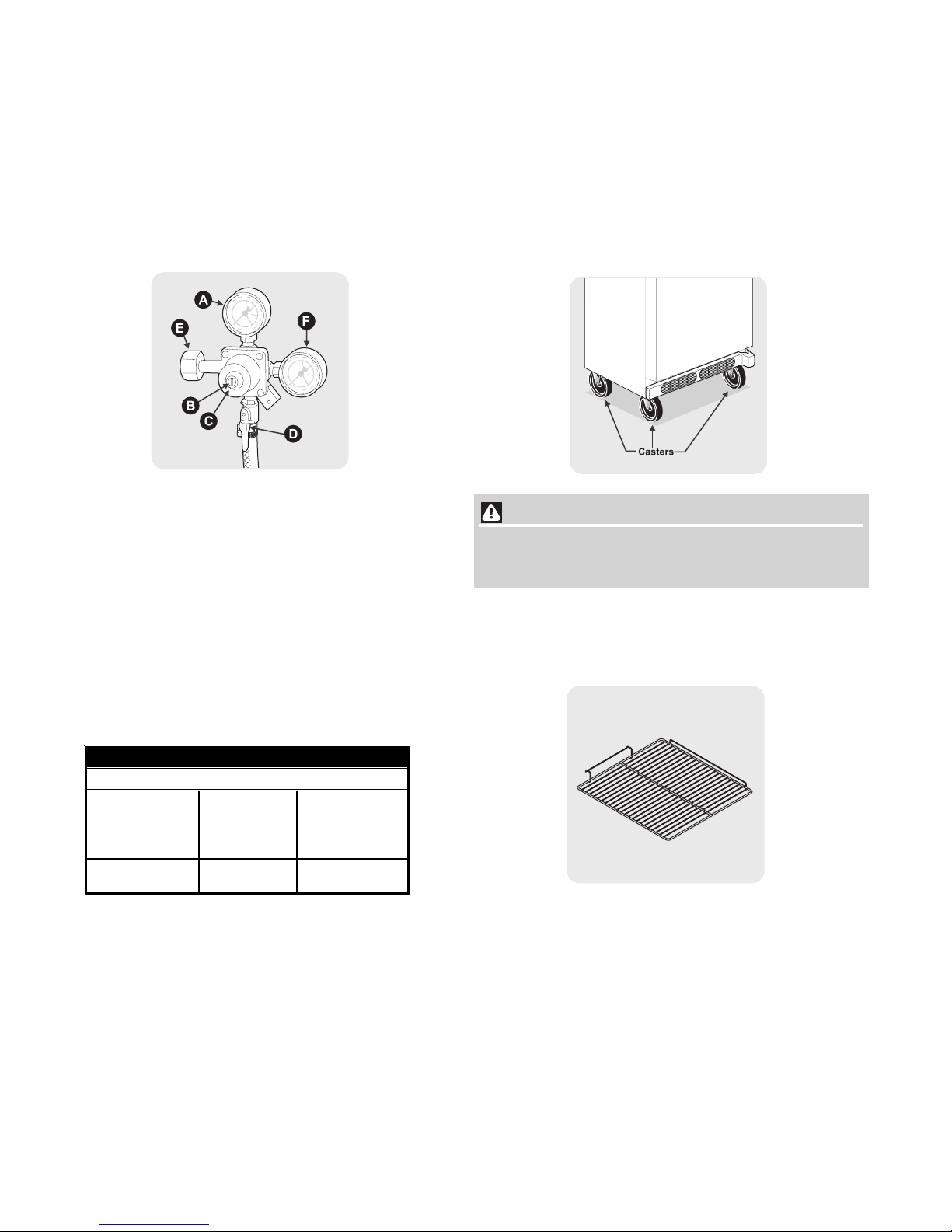
PARTS OF A CO2 REGULATOR
(A) Low Pressure Gauge
(B) Regulator Adjustment Screw
(C) Adjustment Lock Nut
(D) Shut-off Valve
(E) CO
(F) High Pressure Gauge
Nut (used to connect to CO2 Canister)
2
BEER STORAGE TEMPERATURE
• Draft beer is not pasteurized, so it must be kept cold,
preferably at 38ºF. Temperatures above 38ºF may cause
the beer to become wild, turn sour and cloudy.
RECOMMENDED KEG HANDLING
• Be sure the keg is cold when you purchase it.
• Transfer keg from place of purchase and install in
beverage center in 2 hours or less.
• After the keg is installed in the beverage center, allow 24
hours for beverage to reach recommended temperature.
• If the keg is exposed to ambient temperatures longer than
2 hours, additional cooling time will be required before
beverage will reach recommended temperature.
OPTIONAL CASTER KIT
If you’d like to make your beverage center so it can be rolled
from room to room, there is an optional caster kit available
from your authorized Frigidaire dealer or service center. Just
ask for part number
Kit, which includes 2 fixed casters, 2 swivel casters, 2 caster
support rails and mounting hardware.
CAUTIONCAUTION
CAUTION
CAUTIONCAUTION
5304451343 - Caster, Rail and Hardware
DO NOT ATTEMPT TO MOVE OR RELOCATE THIS
BEVERAGE CENTER WITH A KEG INSIDE.
ADJUSTABLE INTERIOR SHELVES
Adjustable interior shelve (P/N 241667701) can be used when
¼ keg is installed.
TYPICAL BEER SERVING EQUIVALENTS
Ounces 992 1984
Gallons 7 ¾ 15 ½
Cases
(12 oz. bottles)
Weight (full)
¼ Keg ½ Keg
3/8 6 ¾
3
82.5 lbs.
(approx.)
165 lbs.
(approx.)
16
OPTIONAL ICE SERVICE
If the beverage center has anoptional automatic ice maker installed , it
will provide a sufficient supply of ice for normal use. However, during
the initial startup of your beverage center, no ice will be produced
during the first 24 hours of operation. Automatic ice makers are also
optional accessories that may be installed in most models at any time.
Call your local dealer for information.
The ice maker produces 2 to 5 pounds of ice every 24 hours
depending on usage conditions. Ice is produced at a rate of 8
cubes every 80 to 160 minutes.
TURNING THE ICE MAKER ON
After the plumbing connections have been completed, the water
supply valve must be opened. Place the ice container under the ice
maker, pushing it as far back as possible. Lower the wire signal arm to
its “down” or ON position. New plumbing connections may cause the
first production of ice cubes to be discolored or have an odd flavor.
These first cubes should be discarded until the cubes produced are free
of discoloration and odd flavor.
NOTENOTE
NOTE
NOTENOTE
For more information on these operations, see
Operating Sounds and Sights
section.
Normal
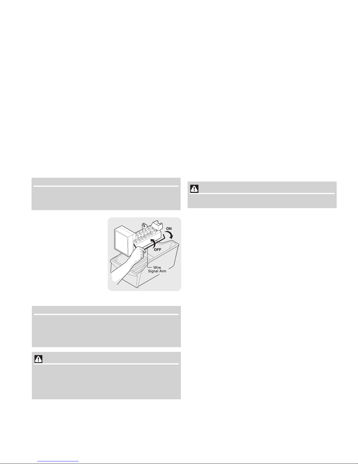
TURNING THE ICE MAKER
OFF
To stop the ice maker, lift the wire
signal arm until it clicks and locks
in the “up” or OFF position. The
ice maker also turns off
automatically when the ice
container is full. If your model has
an adjustable freezer shelf, place
the shelf in the lower position, so
that the wire signal arm will hit the
ice when the container is full.
Ice
Maker
ICE MAKER TIPS
• Ice cubes stored too long may develop an odd flavor.
Empty the ice container and ensure that the wire signal
arm is in its “down” or ON position. The ice maker will then
produce more ice.
• Occasionally shake the ice container to keep ice
separated.
• Keep the wire signal arm in its “up” or OFF position until
the beverage center is connected to the water supply or
whenever the water supply is turned off.
• The following sounds are normal when the ice maker is
operating:
• Motor running
• Ice loosening from tray
• Ice dropping into ice container
• Running water
• Water valve opening or closing
• Wash the ice container in warm water with mild detergent.
Rinse well and dry.
CAUTION CAUTION
CAUTION
CAUTION CAUTION
DO NOT place the ice container in your dishwasher.
• Stop the ice maker when cleaning the freezer and during
vacations.
• If the ice maker will be turned off for a long period of time,
turn the water supply valve to the closed position.
For Service information on the ice maker refer to section “ICE
MAKER” starting on page 53. For instructions on how to install
an ice maker in the product, go to page 71, ICE MAKER
INSTALLATION INSTRUCTIONS.
IMPORIMPOR
IMPOR
IMPORIMPOR
The ice maker is shipped with the wire signal arm in the ON
position. To ensure proper function of your ice maker, hook up
water supply immediately or turn ice maker OFF by lifting the wire
signal arm until it clicks and locks in the UP position.
Chemicals from a malfunctioning softener can damage
the ice maker. If the ice maker is connected to soft water,
ensure that the softener is maintained and working
properly.
TT
ANTANT
T
ANT
TT
ANTANT
CAUTION CAUTION
CAUTION
CAUTION CAUTION
17
NORMAL OPERATING SOUNDS & SIGHTS
UNDERSTANDING THE SOUNDS YOU MAY HEAR
The new high-efficiency beverage center may make unfamiliar sounds.
These are all normal sounds and soon will become familiar to you.
They also indicate your beverage center is operating as designed. Hard
surfaces, such as vinyl or wood floors, walls, and kitchen cabinets may
make sounds more noticeable. Listed below are descriptions of some
of the most common sounds you may hear, and what is causing them.
NOTENOTE
NOTE
NOTENOTE
Rigid foam insulation is very energy efficient, but is not a
sound insulator.
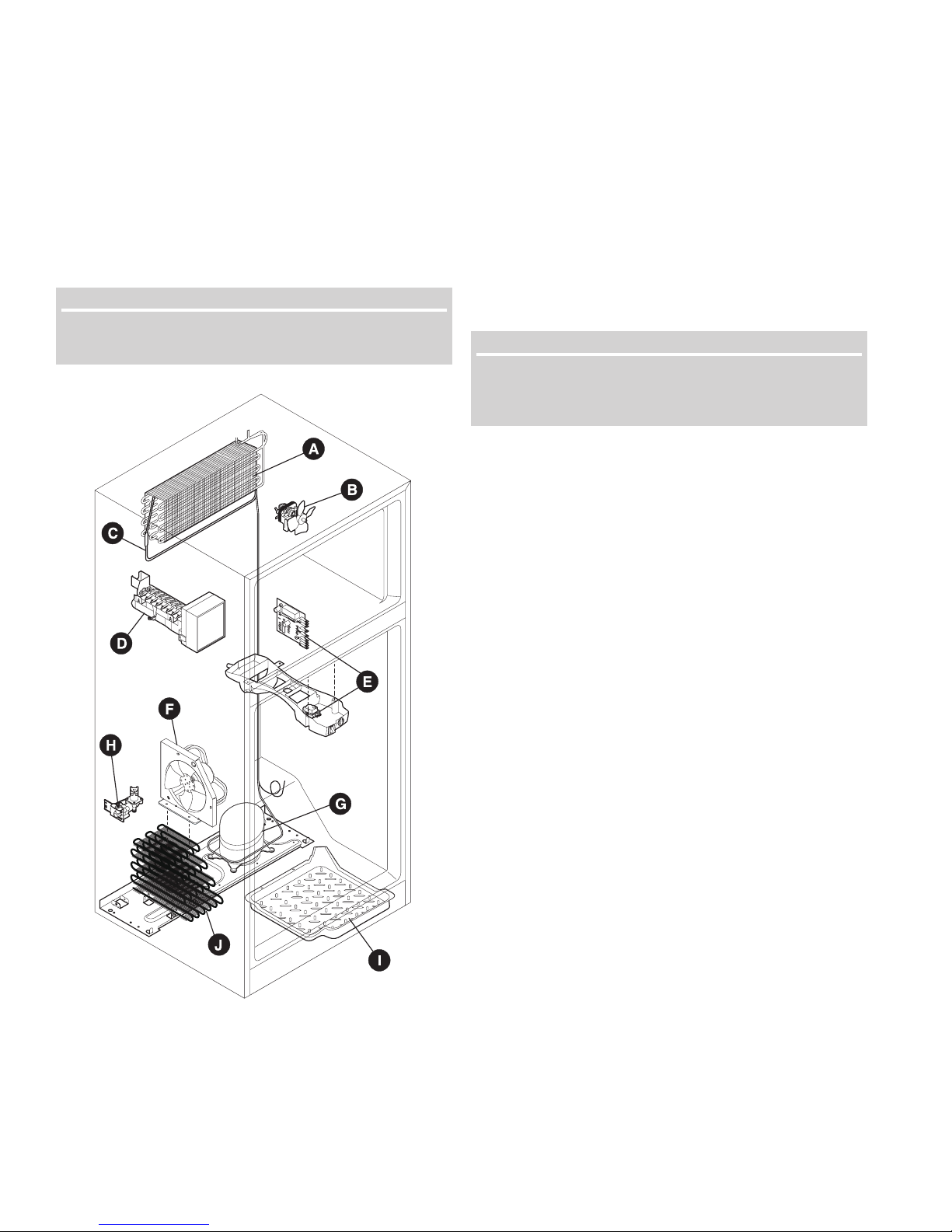
A. Evaporator
The flow of refrigerant through the evaporator may
create a boiling or gurgling sound.
B. Evaporator Fan
You may hear air being forced through the beverage
center by the evaporator fan.
C. Defrost Heater
During defrost cycles, water dripping onto the defrost
heater may cause a hissing or sizzling sound. After
defrosting, a popping sound may occur.
IMPORIMPOR
IMPOR
IMPORIMPOR
During the automatic defrost cycle, you may notice a red
glow in the vents on the back wall of your freezer
compartment. This is normal during the defrost cycle.
TT
ANTANT
T
ANT
TT
ANTANT
D. Automatic Ice Maker
If your beverage center is equipped with an automatic ice
maker, you will hear ice cubes falling into the ice bin.
E. Cold Control & Defrost Timer or Automatic
Defrost Control
These parts can produce a snapping or clicking sound
when turning the beverage center on and off. The timer
also produces sounds similar to an electric clock.
F. Condenser Fan
If condenser coils are located underneath your beverage
center as shown in the drawing at the left, you have a
condenser fan. You may hear air being forced through the
condenser by the condenser fan.
G. Compressor
Modern, high-efficiency compressors operate much
faster than older models. The compressor may have a
high-pitched hum or pulsating sound.
H. Water Valve
If your beverage center is equipped with an automatic ice
maker, you will hear a buzzing sound as the water valve
opens to fill the ice maker during each cycle.
I. Drain Pan (Nonremovable)
You may hear water running into the drain pan during
the defrost cycle. The drain pan is located on top of the
compressor for air-cooled condensers (black coils
on back of beverage center).
J. Condenser Coils (Fan-cooled models only)
May create minimal sounds from forced air.
18

CARE & CLEANING
The customer must keep the beverage center clean to prevent odor build-up. Wipe up any spills immediately and clean both sections at least
twice a year. Never use any type of scouring pads, brushes, abrasive cleaners or strong alkaline solutions on any surface. Do not wash any
removable parts in a dishwasher.
CAUTION CAUTION
CAUTION
CAUTION CAUTION
Always unplug the electrical power cord from the wall outlet before cleaning.
• When moving the beverage center, pull straight out. Do not shift the beverage center from side to side as this may
tear or gouge the floor covering. If the beverage center has an automatic ice maker, be careful not to move the
beverage center beyond the plumbing connections. DO NOT MOVE THE BEVERAGE CENTER WITH A KEG INSIDE.
• Damp objects stick to cold metal surfaces. Do not touch refrigerated surfaces with wet or damp hands.
• Never use CHLORIDE to clean stainless steel.
NOTENOTE
NOTE
NOTENOTE
• Turning the beverage center temperature control to “0” turns off the compressor, but does not disconnect electrical power to
the light bulb or other electrical components. To turn off power to your beverage center, you must unplug the power cord
from the wall outlet.
• Do not use razor blades or other sharp instruments which can scratch the appliance surface when removing adhesive
labels. Any glue left from tape or labels can be removed with a mixture of warm water and mild detergent, or, touch the glue
residue with the sticky side of tape you have already removed. Do not remove the serial plate.
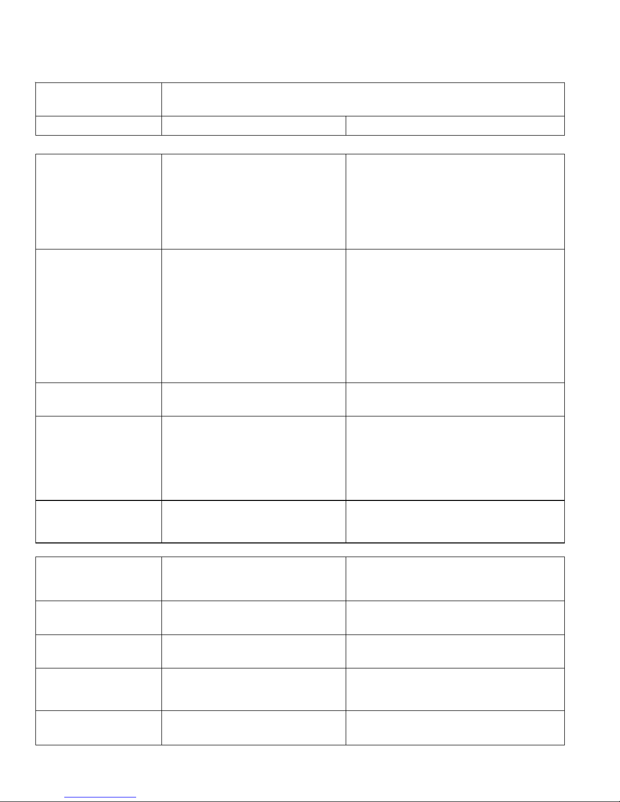
Care & Cleaning Chart
Part What To Use Tips and Precautions
Interior/Door
Liner
Door Gaskets
Drawers/Bins
Toe Grille
Exterior and
Handles
Exterior and
Handles
(Stainless Steel
Models Only)
Condenser
Coils
(Fan-cooled
models only)
Condenser
Coils
(Air-cooled
models only)
Defrost Water
Pan
• Soap and water
• Baking soda and water
• Soap and water
• Soap and water
• Soap and water
• Mild liquid sprays
• Vacuum attachment
• Soap and water
• Soap and water
• Ammonia
• Stainless Steel Cleaners
• Condenser Cleaning
Brush is available from
your dealer.
• Vacuum Cleaner
• Vacuum Cleaner
• Soap and water
Use 2 tablespoons of baking soda in 1 quart of warm water. Be sure to wring
excess water out of sponge or cloth before cleaning around controls,
light bulb or any electrical part.
Wipe gaskets with a clean soft cloth.
Do not wash any removable items (bins, drawers, etc.) in dishwasher.
Vacuum dust from front of toe grille. Remove toe grille (See illustration on
page 7). Vacuum backside and wipe with sudsy cloth or sponge. Rinse and
dry.
Do not use commercial household cleaners, ammonia, or alcohol to clean
handles.
Never use CHLORIDE to clean stainless steel.
Clean stainless steel front and handles with non-abrasive soapy water and a
dishcloth. Rinse with clean water and a soft cloth. Wipe stubborn spots with an
ammonia-soaked paper towel, and rinse. Use a non-abrasive stainless steel
cleaner. These cleaners can be purchased at most home improvement or
major department stores. Always follow manufacturer's instructions.
NOTE: Always clean, wipe and dry with the grain to prevent cross-grain
scratching. Wash the rest of the cabinet with warm water and mild liquid
detergent. Rinse well, and wipe dry with a clean soft cloth.
No need to clean unless operating beverage center under particularly dusty or
greasy conditions, or if there is significant pet traffic in your home. If cleaning
is necessary, remove toe grille and use extended vacuum attachment and
condenser cleaning brush to remove dust build-up from condenser coils (see
item “J” in illustration on page 18 for location).
Use the dusting tool attachment on your vacuum to remove dust build-up on
the condenser coils (black tubes and wires) attached to the back of air-cooled
beverage center only.
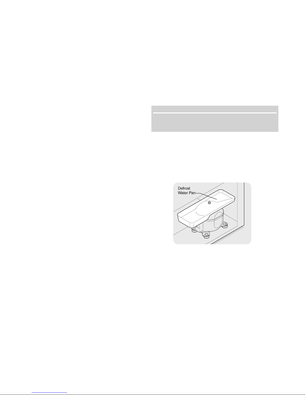
Some models have defrost water pan located on top of compressor at bottom
rear of beverage center (see illustration on next page). Wipe water pan with
damp cloth. NOTE: The defrost water pan is NOT removable.
19
CARE & CLEANING (continued)
PROPER CLEANING OF BEVERAGE CENTER
DISPENSING SYSTEM
The beverage center’s beverage dispensing system needs regular
cleaning and sterilization in order to continue serving draft beer with
its pure brewery flavor. It is recommended that the delivery lines be
cleaned weekly and the entire delivery system cleaned before a new
keg is attached. This is a relatively simple task. You will need the
following parts to clean your unit’s dispensing system. These parts
are available at any draft beer dispensing equipment supplier or call
Electrolux Consumer Services at 1-800-944-9044 for kit CK-1100,
part #
5304443671.
(A) 1 Quart Plastic Cleaning Bottle
(B) Low Profile Hand Pump
(C) Solid Brass Faucet Cleaning Attachment
(D) 4 oz. Bottle of Cleaning Solution
(E) Faucet Wrench
(F) Faucet Cleaning Brush
• Mix one gallon of warm water with one ounce of the
cleaning solution in a bucket.
• Remove the bottle cap and fill the bottle with the solution.
Replace the cap. Do not discard the remaining solution.
• Before removing the delivery line from the tap or from
the coupler, make sure the remaining beverage in the
delivery line is blown out. This can be done by quickly
opening and closing the regulator outlet valve.
• Remove the coupler from keg by rotating it
counterclockwise.
• Remove the braided hose (gas line) from the coupler.
Make sure the canister valve and regulator shut-off valve
is shut off before removing the hose.
• Remove the faucet from the shank assembly by turning
the threaded stainless steel collar clockwise using a
faucet wrench.
• Disassemble the faucet parts and place in the cleaning
solution bucket.
• Attach the brass attachment on the end of the cleaning
hose to the faucet shank assembly by turning the stainless
steel collar counterclockwise. Tighten the collar slightly.
• If the coupler has a shutoff, make sure it is in the open
position.
• Place the keg coupler in the cleaning solution bucket and
pump the cleaning solution through the beer line.
• Clean the faucet parts and keg coupler thoroughly using
the faucet cleaning brush. Also, use the faucet cleaning
brush to clean around the shank and coupling.
• Rinse all the parts with cool fresh water and reassemble
the faucet.
• Detach the cleaning solution bottle from the faucet shank
by turning the threaded stainless steel collar clockwise.
Rinse the bottle with cool fresh water.
• Fill the bottle with fresh water and re-attach it to the faucet
shank assembly. Pump the water through the delivery
line (clear hose). Make sure the end of the line is in a
bucket to collect rinse water.
• Disconnect the cleaner and reinstall the faucet to the
shank by turning the collar counterclockwise using a
faucet wrench and tightening it slightly. DO NOT over
tighten the collar.
• Reattach the braided hose (gas line) to the keg coupler
and open both the canister valve and regulator shut-off
valve.
• Reattach the keg coupler to the keg. Refer to Coupler to
Keg Installation procedures.
• Remove the sump and drip tray from the door and clean
thoroughly. Refer to Cleaning and Maintenance Guide.
• Reinstall the sump and drip tray to the door. Refer to Sump
and Drip Tray Assembly Installation procedures.
NOTENOTE
NOTE
NOTENOTE
Read and follow the instructions that come with the cleaning
kit before cleaning your beverage cooler.
NEVER CLEAN CONDENSER (SOME MODELS)
If the beverage center is equipped with a Never Clean condenser,
there’s no need to clean the condenser under normal operating
conditions. If the beverage center is operated under particularly dusty
or greasy conditions, or if there is significant pet traffic in your home,
it may be necessary to periodically clean the condenser for maximum
efficiency.
Defrost Water Pan (some models)
20

TROUBLESHOOTING GUIDE
TROUBLESHOOTING
GUIDE
PROBLEM CAUSE CORRECTION
This list includes common occurrences that are not the result of defective workmanship or
materials in this appliance.
BEVERAGE CENTER OPERATION
Beverage center does not
run.
Beverage center runs too
much or too long.
Interior beverage center
temperature is too cold.
• Beverage center is plugged into a circuit
that has a ground fault interrupt.
• Temperature control is in the “O” position.
• Beverage center may not be plugged in,
or plug may be loose.
• House fuse is blown or circuit breaker
tripped.
• Power outage.
• Room or outside weather is hot.
• Beverage center has recently been
disconnected for a period of time.
• Doors are opened too frequently or too
long.
• Beverage center door may be slightly
open.
• Temperature control is set too low.
• Beverage center gasket is dirty, worn,
cracked, or poorly fitted.
• Temperature control is set too low. • Adjust temperature control to a warmer setting.
• Use another circuit. If you are unsure about the
outlet, have it checked by a certified technician.
• See SETTING THE TEMPERATURE CONTROL
section.
• Ensure plug is tightly pushed into outlet.
• Check/replace fuse with a 15 amp time-delay fuse.
Reset circuit breaker.
• Check house lights. Call local electric company.
• It’s normal for the beverage center to work harder
under these conditions.
• It takes 4 hours for the beverage center to cool
down completely.
• Warm air entering the beverage center causes it
to run more. Open door less often.
• See “DOOR PROBLEMS” section.
• Adjust temperature control to a warmer setting.
Allow several hours for temperature to stabilize.
• Clean or change gasket. Leaks in the gasket will
cause beverage center to run longer in order to
maintain desired temperature.
Allow several hours for temperature to stabilize.
Interior beverage center
temperature is too warm.
Beverage center external
surface temperature is
warm.
SOUND AND NOISE
Louder sound levels
whenever beverage center
is on.
Longer sound levels when
compressor comes on.
Fan runs when room
temperature is below 45° F
Popping or cracking sound
when compressor comes
on.
• Temperature control is set too warm.
• Door is kept open too long or is opened
too frequently.
• Door may not be seating properly.
• Beverage center has recently been
disconnected for a period of time.
• The external walls can be as much as 30°
F warmer than room temperature.
• Modern beverage centers have increased
storage capacity and more stable
temperatures. They require a high
efficiency compress or.
• Beverage center operates at high
pressures during the start of the “ON”
cycle.
• Exterior thermostat has activated the
heater and fan.
• Metal parts undergo expansion and
contraction, as in hot water pipes.
• Adjust temperature control to a colder setting.
Allow several hours for the temperature to
stabilize.
• Warm air enters the beverage center every time
the door is opened. Open the door less often.
• See “DOOR PROBLEMS” section.
• It takes 4 hours for the beverage center to cool
down completely.
• This is normal while the compressor works to
transfer heat from inside the beverage center.
• This is normal. When the surrounding noise level
is low, you might hear the compressor running
while it cools the interior.
• This is normal. Sound will level off or disappear as
the beverage center continues to run.
• This is normal.
• This is normal. Sound will level off or disappear as
beverage center continues to run.
Bubbling or gurgling sound
like water boiling.
• Refrigerant (used to cool beverage
center) is circulating throughout the
system.
• This is normal.
22
TROUBLESHOOTING GUIDE
SOUND AND NOISE (CONT.)
Vibrating or rattling noise.
Snapping noise
WATER / MOISTURE / FROST INSIDE BEVERAGE CENTER
Moisture forms on inside of
beverage center walls.
WATER / MOISTURE / FROST OUTSIDE BEVERAGE CENTER
Moisture forms on outside
of beverage center walls.
ODOR IN BEVERAGE CENTER
Unpleasant odors.
DOOR PROBLEMS
Door will not close.
COMMON DRAFT PROBLEMS
WILD BEER – Beer, when
drawn, is all foam, or too
much foam and not enough
liquid beer.
FLAT BEER – Foamy
head disappears quickly;
beer lacks usual zestful
brewery fresh flavor
CLOUDY BEER – When
beer in glass appears
hazy, not clear.
• Beverage center is touching the wall. • Move beverage center slightly away from the wall.
• Temperature control turning beverage
center on and off.
• Weather is hot and humid.
• Door may not be seating properly.
• Door is kept open too long or opened too
frequently.
• Door may not be seating properly, causing
the cold air from inside the beverage
center to meet warm moist air from the
outside.
• Interior needs to be cleaned. • Clean interior with sponge, warm water, and
• Beverage center is not level. • This condition can force the cabinet out of square
• Beer drawn improperly.
• Creeping regulator.
• Applied pressure is set too high.
• Hot spots in line.
• Tapped into a warm keg
(should be 34°F ~ 38°F)
• Center malfunctioning.
• Faucet is in bad, dirty or worn condition.
• Dirty glasses.
• Applied pressure is set too low.
• CO
is cut off.
2
• Beer too cold.
• Loose tap or vent connections.
• Sluggish regulator.
• Frozen or near frozen beer.
• Unrefrigerated beer for long periods of
time.
• Dirty glasses.
• Dirty faucet.
• Unrefrigerated foods placed on top of cold
keg.
• This is normal
• This is normal.
• See “DOOR PROBLEMS: section.
• Open the door less often.
• See “DOOR PROBLEMS: section.
baking soda.
and misalign the door. Level the unit.
• Make sure faucet is opened all the way. Close
quickly when done.
• Replace regulator
• Readjust regulator to a lower pressure until foam
subsides. When pressure is properly set, you
should be able to pour 10 oz. of beer in 5 seconds.
• Make sure beer delivery line is not pinched and is
fully inside the interior of the beverage center.
• Wait until keg cools down to proper temperature.
• Have beverage center serviced to return it to
proper operating condition.
• Thoroughly clean faucet with recommended
cleaning kit. Replace all worn seals.
• Wash glasses using soap-free detergent.
• Increase pressure until beer flows at a rate of 2 oz.
per second.
• Do not turn off CO
empty and ready to be removed.
• Increase temperature of beverage center. See
SETTING THE TEMPERATURE CONTROL
section.
• Check that coupler is properly installed in keg.
• Replace regulator.
• Return keg to place of purchase and exchange for
one that has been properly refrigerated.
• Exchange keg for fresh one.
• Wash glasses using soap-free detergent.
• Clean faucet with recommended cleaning kit.
• Remove items from atop keg and place in a
separate refrigerator.
supply line to keg until keg is
2
23
 Loading...