


ELECTROLUX HOME PRODUCTS NORTH AMERICA
SERVICE MANUAL
3.0 Cu. Ft. HORIZONT AL
AXIS WASHER
5995413084
GOOD & BETTER MODELS
W hite-Westinghouse
December 2004
1
1111111

SAFE SERVICING PRACTICES - ALL APPLIANCES
To avoid personal injury and/or property damage, it is important that Safe Servicing
Practices be observed. The following are some limited examples of safe practices:
1. DO NOT attempt a product repair if you have any doubts as to your ability to
complete it in a safe and satisfactory manner.
2. Before servicing or moving an appliance:
• Remove the power cord from the electrical outlet, trip the circuit breaker to the
OFF position, or remove the fuse.
• Turn off the gas supply.
• Turn off the water supply.
3. Never interfere with the proper operation of any safety device.
4. USE ONLY REPLACEMENT PARTS CATALOGED FOR THIS APPLIANCE.
SUBSTITUTIONS MAY DEFEAT COMPLIANCE WITH SAFETY
STANDARDS SET FOR HOME APPLIANCES.
5. GROUNDING: The standard color coding for safety ground wires is GREEN, or
GREEN with YELLOW STRIPES. Ground leads are not to be used as current
carrying conductors. It is EXTREMELY important that the service technician
reestablish all safety grounds prior to completion of service. Failure to do so will
create a hazard.
6. Prior to returning the product to service, ensure that:
• All electrical connections are correct and secure
• All electrical leads are properly dressed and secured away from sharp edges,
high-temperature components, and moving parts
• All non-insulated electrical terminals, connectors, heaters, etc. are adequately
spaced away from all metal parts and panels
• All safety grounds (both internal and external) are correctly and securely
connected
• All panels are properly and securely reassembled
ATTENTION!!!
This service manual is intended for use by persons having electrical and mechanical
training and a level of knowledge of these subjects generally considered acceptable in the
appliance repair trade. Electrolux Home Products cannot be responsible, nor assume any
liability, for injury or damage of any kind arising from the use of this manual.
© 2001 White Consolidated Industries
2

SAFE SERVICING PRACTICES 2
Model lines 7
QUICK REFERENCE SHEET 8
Serial nameplate location 8
Serial number breakdown 8
T ech sheet location 8
Component resistance chart 9
Water fill height 9
Electrical requirements 9
Incoming water pressure 9
Drain requirements 9
Motor 9
Tub pulley to motor pulley ratio 9
Tub capacity 9
Auto temp control temperature specifications 9
Diagnostic test 10
Operation speeds 1 1
Sample schematic (Good Models) 1 2
Sample schematic (Better Models) 1 3
Operation chart 14
SECTION A - INST ALLA TION INSTRUCTIONS 15
What to do if you smell gas 1 5
Pre-installation requirements 1 5
T ools required for inst allation 1 5
Electrical requirements 1 5
Circuit 15
Power supply 1 5
Outlet receptacle 15
Grounding requirements 1 5
Water supply requirements 1 6
Drain requirements 1 6
Rough-in dimensions 17
Location of your washer 1 9
Do not install your washer 1 9
Minimum installation clearances 19
Unpacking 19
Drain hose installation 2 0
Installation 21
Replacement parts 22
SECTION B - Washer & Dryer Pedestal Installation Instructions 2 3
Washer Installation 2 3
Dryer installation 2 5
Warranty 27
SECTION C - OPERA TING INSTRUCTIONS 28
Before operating your washer 28
Operating steps 28
Cycle selection 29
Heavy duty 29
Normal wash 2 9
Perm press 2 9
Quick 29
Sport 29
Delicates 29
Handwash 29
Soak 29
Drain/spin 29
3

Rinse/spin 29
Cycle settings 30
Wash/rinse water temperature 30
Final spin speed 3 0
Water level 30
Cycle options 30
Heavy soil/stain 30
Extra rinse 3 0
Extra spin 30
Cycle signal 3 0
Washer features 3 0
Delay start 3 0
Control lock 3 0
Status lights 30
Washer settings chart 31
Error code chart 3 2
SECTION D - USE & CARE GUIDE 3 3
Product record 33
Y our safety and the safety of others is very important 3 3
Pedestal 33
Important safety instructions 3 3
Read all instructions before using this washer 3 3
Prevent fire 33
Protect Children 3 3
Prevent Injury 34
Washing procedures 35
Sort laundry into loads that can be washed together 35
Prepare items for washing 36
Pretreat stains and heavy soil 3 6
Add laundry load to washer 36
Add detergent, bleach and fabric softener to automatic dispenser 3 7
Start the washer 38
Remove items when the cycle is completed 38
General precautions 38
Stain removal 39
Safe stain removal procedures 4 0
Stain removal 40
Common washing problems 4 1
Care and cleaning 42
Outside 42
Cleaning the dispenser drawer area 42
Winterizing instructions 43
Avoid service checklist 44
Warranty 47
SECTION E - OPERA TION 48
Control 48
Dispenser Drawer Reed Switch 4 8
Door Switch Assembly 48
Pressure Switch 49
Electronic water level sensor 5 0
Water Inlet Valve 50
Auto T emp System (Better Models) 5 2
Automatic Dispenser 52
Drain Pump 56
Speed Control 57
Motor 57
4

SECTION F - CONSTRUCTION 58
Cabinet 58
Front Panel and Door Assembly 5 8
Bellows (Door Boot) 58
Outer T ub Assembly 58
Spin Basket Assembly 58
SECTION G - TROUBLESHOOTING 59
Failure code chart 60
T est 61
Jacks and plugs 63
SECTION H - TEARDOWN 6 4
Removing the detergent drawer 64
Detergent drawer disassembly 6 4
Removing door strike 6 5
Removing the door handle 65
Removing loading door 65
Disassembling the door 68
Removing loading hinges 6 8
Releasing the bollows from the front panel 67
Removing the door safety switch 6 7
Removing the front service panel 68
Removing the drain pump assembly 6 8
Disassembling the drain pump 6 9
Removing the top panel 69
Removing the pressure switch 7 0
Removing the electronic water level sensor 70
Releasing the console 70
Removing the reed switch 7 1
Removing the water temperature selector knob (Good Models) 7 1
Removing the console 7 2
Removing the electronic control 7 2
Removing the selector knob (Good Models) 7 2
Removing the water temperature selector shaft (Good Models) 7 2
Removing the selector dial (Better Models) 7 3
Removing the selector knob (Better Models) 7 3
Removing the programing buttons and springs 7 3
Removing the front panel 73
Removing the console mounting brace 7 4
Removing the bellow or boot 74
Reinstalling or replacing the boot 75
Removing the weight ring 77
The water inlet and overflow/vent tube grommet 77
Removing the water inlet grommet 77
Removing the overflow/vent tube grommet 78
Removing the overflow/vent tube 78
Removing the water inlet valve assembly 79
Removing the water inlet screens 80
Removing the top rear brace 80
Removing the suspension springs 80
Removing the top center brace 81
Removing the detergent cavity assembly 8 1
Removing the detergent dispenser outlet hose 8 3
Removing the siphon break hose 8 3
Removing the drain sump 8 3
Removing the hose between the drain pump and the drain hose coupler 83
Removing the external drain hose 84
5

Removing the drain hose coupler 84
Removing the rear access panel 85
Drive belt 85
To remove or replace the drive belt 85
Removing the large pulley 85
Removing the drive motor 8 6
Removing the speed control board assembly 8 6
Removing the right hand air shock absorber 8 8
Removing the left hand air shock absorber 8 8
To remove the air bell 89
Removing the tub assembly 8 9
Removing the spin basket and rear tub half 9 1
Removing the spin basket vanes 9 2
6
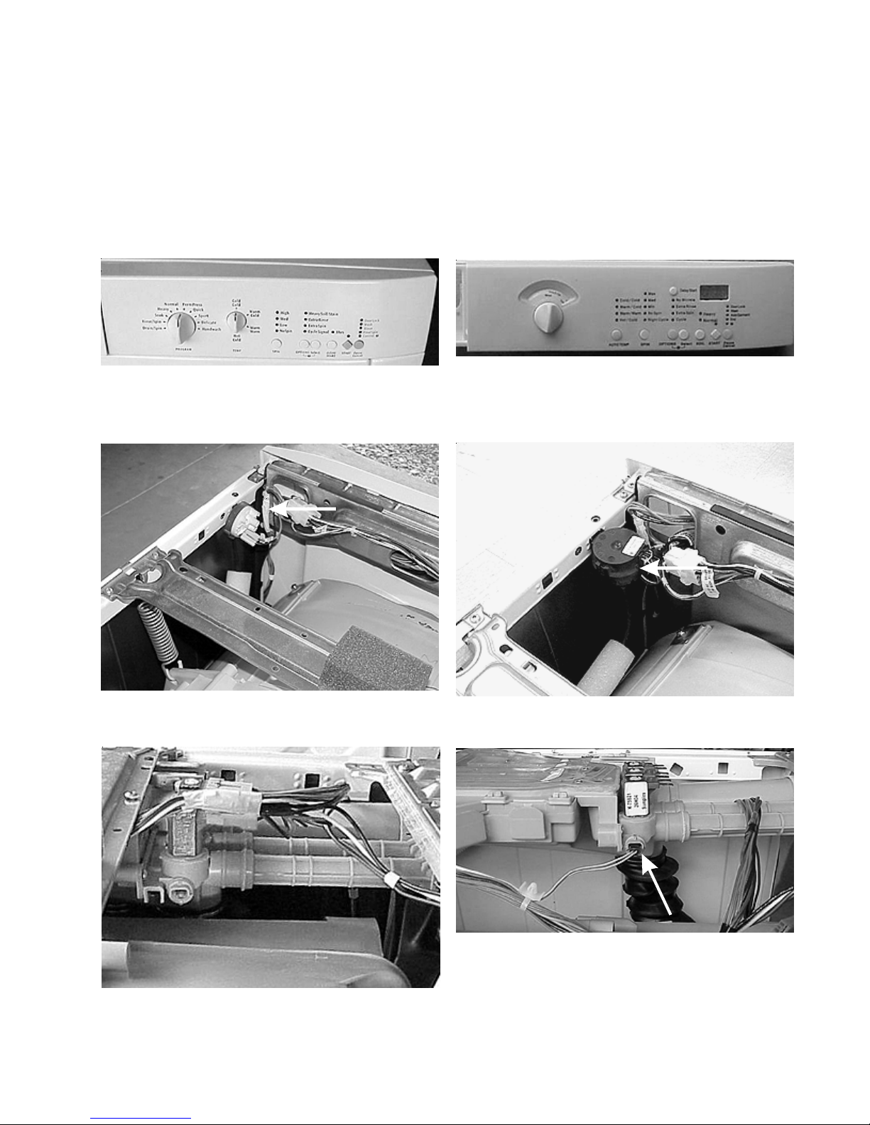
Model Lines
This manual will cover the Good and Better model lines of the 3.0 Cu. Ft. HORIZONT AL AXIS W ASHER.
Differences:
Good Models
1. Control panel does not have a display .
2. Water fill height control is a pressure switch.
Better Models
1. Control panel has a display .
2. Water fill height control is a electronic pressure
sensor.
3. Does not have a water temperature sensor.
3. Has a water temperature sensor.
7
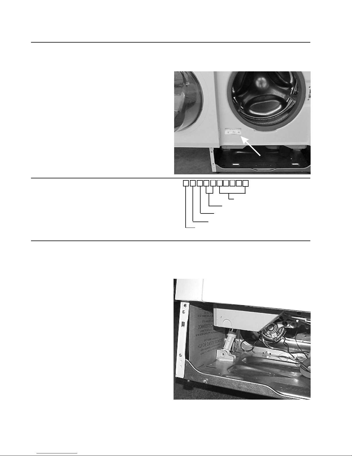
QUICK REFERENCE SHEET
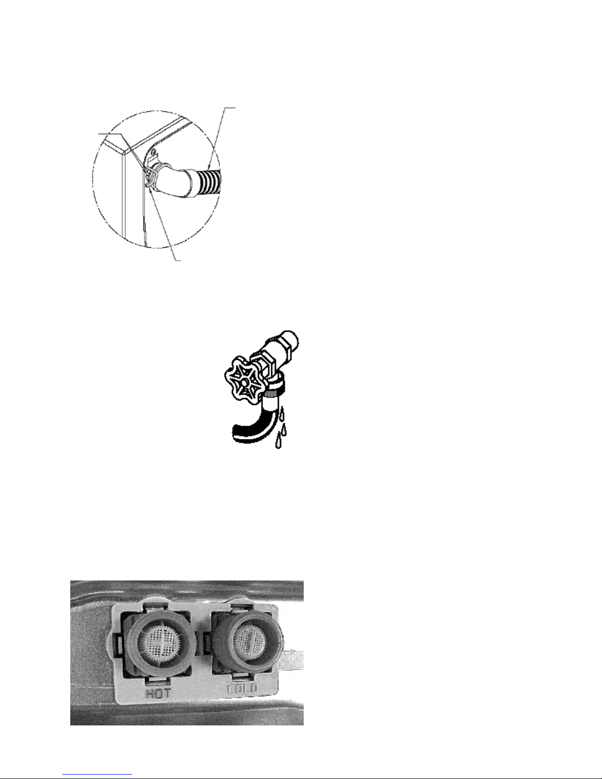
1. Serial nameplate location:
2. Serial number breakdown.
On the front panel at the lower left of the
washer door opening.
X C 4 4 8 1 5 6 9 3
Incremented unit number
Production week
Last digit of production year
Product identification
Manufacturing facility
3. Tech sheet location
On the lefthand bodyside behind the front
access panel.
8
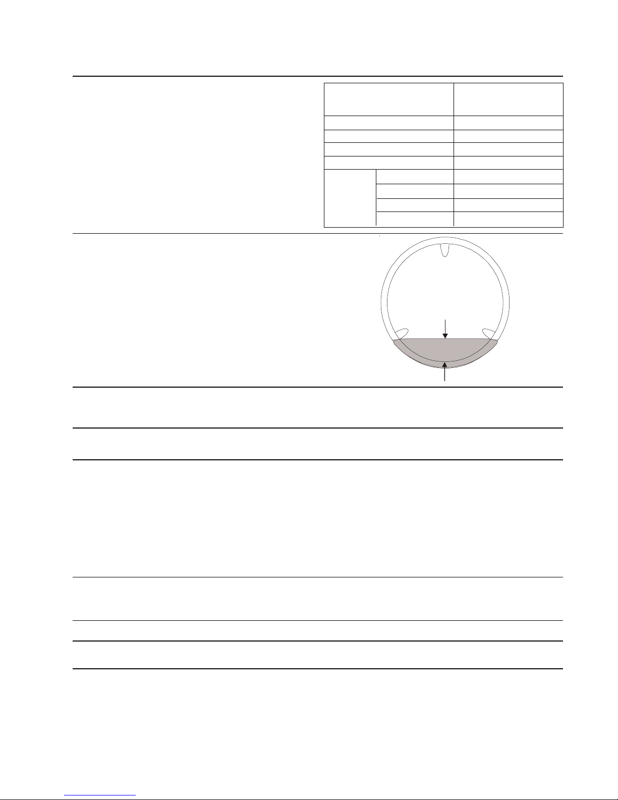
QUICK REFERENCE SHEET
Component resistance chart.
Good Models
Water fill height 3 ± .5 “
No load, start position of permanent press cycle.
Better Models
Water fill height dependent upon selected cycle.
Resistance Ω
Electrical component @ 77° F (25°C)
Dispenser valve solenoids 800 ± 7%
Door lock solenoid 1325 ± 10%
Pump motor 12 ± 7%
NTC Thermistor 50K ± 2%
M1 TO M2 5.3 ± 7%
Motor
M2 TO M3 5.3 ± 7%
M1 TO M3 5.3 ± 7%
M4 TO M5 118 ± 7%
Electrical requirements.
Incoming water pressure.
Drain requirements.
Motor.
Tub Pulley to Motor Pulley Ratio. 16 TO 1
Tub Capacity. 3.0 cu. ft.
Automatic T emperature Control S pecifications. (Better Models).
Regulated hot wash temperature 130° ± 7° F
Regulated warm wash and rinse temperature 90° ± 7° F
Regulated cold wash and rinse temperature 65° ± 7° F
Circuit - Individual, properly polarized and grounded 15
amp. branch circuit fused with 15 amp. time delay fuse
or circuit breaker.
30 and 120 pounds per square inch (maximum
unbalance pressure, hot vs. cold, 10 psi.)
Drain capable of eliminating 17 gals (64.3 L) per minute.
A standpipe diameter of 1-1/4 in. (3.18 cm) minimum.
The standpipe height above the floor should be:
Minimum height: 24 in. (61 cm)
Maximum height: 96 in. (244 cm)
No load agitate wattage - Max 150
No load spin wattage - Max 550
9

Diagnostic T est:
The diagnostic test is performed by using the Program
Knob. T o ST ART THE TEST :
• On non-digital display models, turn the
Program Knob to
start position, Drain/Spin.
• On digital display models, turn the Program
Knob to start position, Drain/Spin.
• Press Pause/Cancel to turn off LEDs.
• Within 5 seconds, press and hold the Optionand
Pause/Cancel buttons until LEDs start
sequentially chasing, then release buttons.
1. All the LEDs will sequentially light. Pressing a
button below a light cluster will light all the LEDs in
that cluster at one time to confirm functionality .
2. Turn the program knob (1) click clockwise from the
start position. The hot water solenoid will activate
and hot water should enter through the detergent
compartment.
3. Turn the program knob (2) clicks from the start
position. The bleach water solenoid will activate and
cold water should enter through the bleach
compartment.
4. Turn the program knob (3) clicks from the start
position. The bleach and the wash water solenoids
will activate and cold water should enter through the
softener compartment.
5. Turn the program knob (4) clicks from the start
position. The door lock solenoid will activate.
6. Turn the program knob (5) clicks from the start
position. The door lock solenoid will deactivate and
the loading door can be opened.
10. Turn the program knob (9) clicks from the start
position. The control will signal the last error code.
See Section F, Troubleshooting, for det ails for
properly identifying the error code on non-digital
display models.
Exiting Diagnostic Mode
There are two options for exiting the Diagnostic T est mode
and returning the washer to normal operation:
a) Unplug the power cord, wait 5-8 seconds, then
reconnect the power cord OR
b) Turn the program knob clockwise 2 or 3 clicks after
the Start Position. Press Options and Pause/Cancel
buttons together for a few seconds until wash cycle
LEDs appear.
If a situation arises where you cannot exit the
Diagnostic mode as described above and the bank
of 5 LED’s on the right end remain ON regardless of
Program Knob position, a combination of pushed
buttons caused the control to enter a special factory
test mode. Disconnect power to reset the control to
return washer to normal operation is this occurs.
T o clear latest stored error code:
Place the control into Diagnostic test Mode.
• Turn the program knob clockwise 9 clicks from the
Start Position. The control will signal the last error
code.
• Press and hold the Options and Pause/Cancel
buttons for 3 seconds. The code will be cleared.
• Exit Diagnostic Mode to return the washer to normal
operation.
7. Turn the program knob (6) clicks from the start
position. The washer will fill and tumble.
8. Turn the program knob (7) clicks from the start
position. The washer will fill and spin (leakage test).
9. Turn the program knob (8) clicks from the start
position. The drain pump and door lock solenoid will
activate and the washer will operate in high spin.
SAFETY WARNING: If power is removed during this
test, the door can be opened. T o prevent injury , DO
NOT put your hands inside when the tub is rotating
10
OPERATION SPEEDS
GOOD MODELS
Agitation
Speed
CYCLE High Medium Low Hang Dry
Heavy 47 1000 900 850 NA
Normal 47 1000 900 850 NA
EcoNormal47NANANANA
Perm Press 47 900 850 800 450
Quick 47 1000 900 850 NA
EcoQuick 47 NA NA NA NA
Delicate 32 450 400 350 350
Handwash 32 450 400 350 350
Touch Up 47 1000 900 850 450
Drain Spin NA 1000 900 850 450
Rinse Spin NA 1000 900 850 450
Soak 47 450 400 350 NA
Wool 32 NA NA NA NA
Silk 32 NA NA NA NA
Bulky 47 900 850 800 NA
Sport 47 900 850 800 450
Towels 47 NA NA NA NA
Jeans 47 NA NA NA NA
Spin
Speeds
BETTER MODELS
Agitation
Speed
CYCLE High Medium Low Hang Dry
Heavy 47 1100 1000 950 NA
Normal 47 NA NA NA NA
EcoNormal 47 1100 1000 950 NA
Perm Press 47 900 850 800 450
Quick 47NANANANA
EcoQuick 47 1100 1000 950 NA
Delicate 32 450 400 350 350
Handwash 32 450 400 350 350
Touch Up 47 1100 1000 950 450
Drain Spin NA 1100 1000 950 450
Rinse Spin NA 1100 1000 950 450
Soak 47 450 400 350 NA
Wool 32 450 400 350 NA
Silk 32 NA NA NA NA
Bulky 47 900 850 800 NA
Sport 47 900 850 800 450
Towels 47 1100 1000 950 NA
Jeans 47 1100 1000 950 NA
Spin
Speeds
11
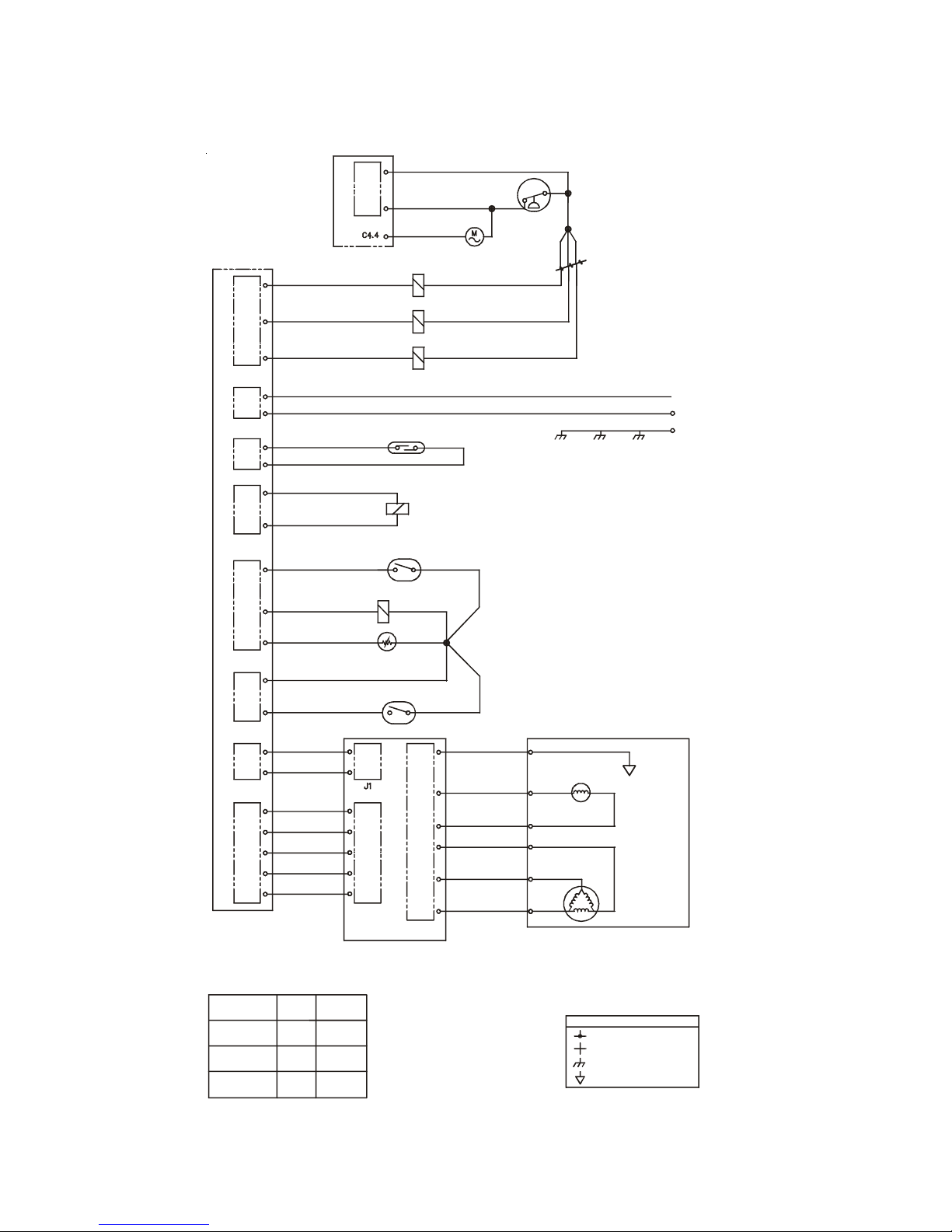
SAMPLE SCHEMATIC FOR GOOD MODELS
J14
J8
J3
J2
2
BLACK/RED
1
PUMP
BLACK/RED
BLACK/RED
BLACK/RED
RED/BLK
GRN
GRAY
WHT
BRN
RED
ORG
2
1
2
PRESSURE
SWITCH
CABINET TUB
C5.5
C5.4
C5.3
C5.2
C5.1
GREEN
TAC HO
GENERATOR
1
2
T
X
Y
MOTOR
Z
SPEED
CONTROL
MOTOR
FRAME
L1
N
GROUND
C3.2
J5
TAN/BLK
C3.1
J4
PURP
C4.3
J4
J7
J1
J6
C4.2
C4.1
C2.1
C2.2
C2.1
C2.2
C3.1
C3.3
C5.1
C5.3
C5.5
C2.2
C2.1
C2.1
C2.2
C5.5
C5.4
C5.3
C5.2
C5.1
TAN
RED
BLK
WHT
BLK
BLK
BRN
YEL
ORG
GRAY
PINK
RED/BLK
BLK
BLU
BLK
RED
WHT
BLK
BLU
YEL
AUXILIARY SWITCH
C2.2
MOTOR CONTROL BOARD
PINK/BLK
COLD 1
COLD 2
HOT
DISPENSE R DRA WER
REED SWITCH
1
+T NTC
(SELECT MODELS)
DOOR LOCK
4.1 4.2
DOOR LOCK
2.1 4.4
3.1
3.3
WAX MOTOR
DOOR SWITCH
2.2 4.3
C2.1
C5.1
C5
C5.3
C5.4
C5.5
J3
C7.1
C7.3
C7.4
.2
C7.5
C7.6
C7.7
J5
DISPENSE R VALVE
EVENT
DETERGENT
BLEACH
SOFTNER
X = CLOSED O = OPEN
COLD 1
O
X
X
COLD 2
X
O
X
12
WIRING CODES
CONNECTION
NO CONNECTION
CABINET GROUND
LOCAL GROUND
/
/
/
/
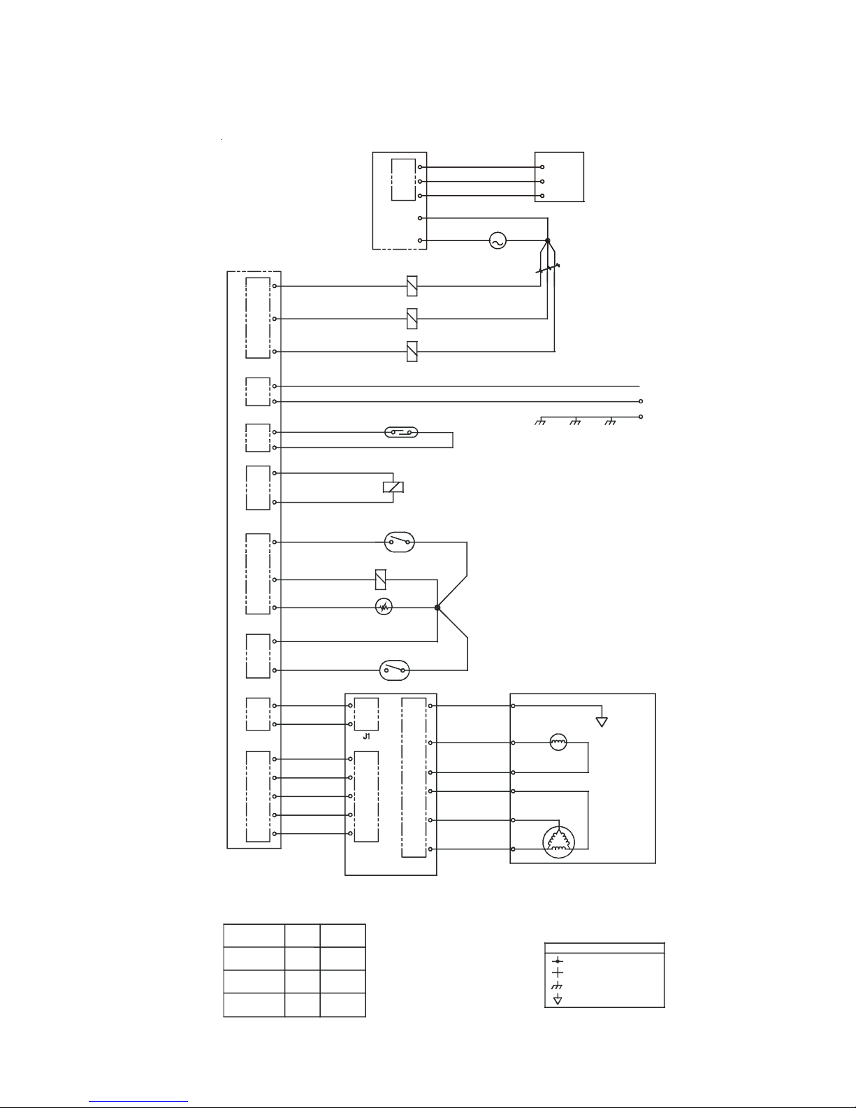
SAMPLE SCHEMATIC FOR BETTER MODELS
LEVEL SENSOR
BLACK/RED
PINK/BLK
BLACK
BLU
WHT
RED
1
PUMP
RED
C5.5
C5.3
C5.1
M
2
C4.3
PURP
J9
J5
J4
BLEACH
C4.2
C4.3
C4.4
C3.1
C4.4
J14
J8
J3
J2
J4
J7
J1
J6
C4.2
C4.1
C2.1
C2.2
C2.1
C2.2
C3.1
C3.3
C5.1
C5.3
C5.5
C2.2
C2.1
C2.1
C2.2
C5.5
C5.4
C5.3
C5.2
C5.1
TAN
RED
BLK
WHT
BLK
BLK
BRN
YEL
ORG
GRAY
PINK
RED/BLK
BLK
BLU
BLK
RED
WHT
BLK
BLU
YEL
WASH
HOT
DISPENSE R DRA WER
REED SWITCH
1
DOOR LOCK
AUXILIARY SWITCH
4.1 4.2
DOOR LOCK
2.1 4.4
3.1
WAX MOTOR
DOOR SWITCH
2.2 4.3
C2.1
C2.2
C5.1
C5.2
C5.3
C5.4
C5.5
J3
MOTOR CONTROL BOARD
2
+T NTC
(SELECT MODELS)
3.3
C7.1
C7.3
C7.4
C7.5
C7.6
C7.7
J5
RED
BLACK
BLACK
BLK
GRN
GRAY
WHT
BRN
RED
ORG
RED
RED
GREEN
CABINET TUB
TAC HO
GENERATOR
1
C5.5
C5.4
C5.3
C5.2
C5.1
Y
MOTOR
2
T
X
Z
SPEED
CONTROL
MOTOR
FRAME
L1
N
GROUND
DISPENSE R V A L V E
EVENT
DETERGENT
BLEACH
SOFTNER
X = CLOSED O = OPEN
COLD 1
O
X
X
COLD 2
X
O
X
13
WIRING CODES
CONNECTION
NO CONNECTION
CABINET GROUND
LOCAL GROUND
OPERA TION CHART
Wash Cycle Wash Phase *Estimated
Step Time
(sec)
Heavy Fill and Tumble 6 0
Fill Then Tumble 3 0 0
(Heavy opt.) Fill Then Tumble 1 2 0
(Normal) Fill Then Tumble 66 0
Tumble 120
Drain/spin 180
Rinse/Spin Fill and Tumble 9 0
Fill Then Tumble 18 0
Drain/spin 180
Fill and Tumble 90
Fill Then Tumble 18 0
Drain/spin 180
Extra Rinse Fill and Tumble 90
Fill Then Tumble 24 0
Drain/spin 180
Fill and Tumble 90
Fill Then Tumble 120
Drain 3 0
Spin 570
Extra spin Spin 1 80
Tumble 150
*Estimated Cycle Time (min) Stop 53
Pump Dispenser
OFF Wash (Det)
OFF Wash (Det)
OFF Wash (Det)
OFF Wash (Det)
OFF OFF
ON OFF
OFF BLEACH
OFF BLEACH
ON OFF
OFF BLEACH
OFF BLEACH
ON OFF
OFF BLEACH
OFF BLEACH
ON OFF
OFF FABRIC
OFF FABRIC
ON OFF
ON OFF
ON OFF
OFF OFF
OFF OFF
Wash Cycle Wash Phase *Estimated Pump Dispenser
Step Time
(sec)
Normal Fill and Tumble 60
Fill Then Tumble 30 0
(Normal) Fill Then Tumble 18 0
(Light) Fill Then Tumble 30 0
Tumble 120
Drain/spin 60
Rinse/Spin Fill and Tumble 9 0
Fill Then Tumble 18 0
Drain/spin 180
Fill and Tumble 90
Fill Then Tumble 18 0
Drain/spin 180
Extra Rinse Fill Then Tumble 90
Fill Then Tumble 18 0
Drain/spin 180
Fill and Tumble 90
Fill Then Tumble 180
Drain 3 0
Spin 570
Extra spin Spin 1 80
Tumble 150
*Estimated Cycle Time (min) Stop 49
OFF Wash (Det)
OFF Wash (Det)
OFF Wash (Det)
OFF Wash (Det)
OFF OFF
ON OFF
OFF BLEACH
OFF OFF
ON OFF
OFF BLEACH
OFF OFF
ON OFF
OFF BLEACH
OFF BLEACH
ON OFF
OFF FABRIC
OFF FABRIC
ON OFF
ON OFF
ON OFF
OFF OFF
OFF OFF
14

SECTION A - Installation Instructions
4. Carpenter’s level.
ELECTRICAL REQUIREMENTS
Full Size Tumble Action Washers
Before beginning installation, carefully read these
instructions. This will simplify the
installation and ensure the washer is installed
correctly and safely. Leave these instructions
near the washer after installation for future reference.
NOTE: The electrical service to the washer must
conform with local codes and ordinances
and the latest edition of the National Electrical
Code, ANSI/NFP A 70.
For your safety the information in
this manual must be followed to minimize the risk
of fire or explosion or to prevent property damage,
personal injury or loss of life.
-Do not store or use gasoline or other flammable
vapors and liquid in the vicinity of this or any other
appliance.
CIRCUIT - Individual, properly polarized and grounded
15 amp. branch circuit fused with 15 amp. time delay
fuse or circuit breaker.
POWER SUPPL Y - 2 wire, with ground, 120 volt, single
phase, 60 Hz, Alternating Current. NOTE: The use of
this washer with power created by gas powered
generators, solar powered generators, wind powered
generators or any other generator other than the local
utility company is not recommended.
OUTLET RECEPT ACLE - Properly grounded 3-prong
receptacle to be located so the power supply cord is
accessible when the washer is in an installed position.
WHA T TO DO IF YOU SMELL GAS
· Do not try to light any appliance.
· Do not touch any electrical switch; do not use any
phone in your building.
· Clear the room, building or area of all occupants.
· Immediately call your gas supplier from a
neighbor’s phone. Follow the gas suppliers
instructions.
· If you cannot reach your gas supplier, call the fire
department.
Installation and service must be performed by a
qualified installer , service agency or the gas supplier.
PRE-INSTALLATION REQUIREMENTS
T ools Required for Installation:
1. Phillips screwdriver
2. 10 mm socket with ratchet.
3. Channel-lock adjustable pliers.
NOTE: GFI (Ground Fault Interrupter) receptacle is not
required.
GROUNDING REQUIREMENTS
Improper connection of the
equipment grounding conductor can result in a risk of
electrical shock. Check with a licensed electrician if you
are in doubt as to whether the appliance is properly
grounded.
1. The washer MUST be grounded. In the event of
malfunction or breakdown, grounding will reduce the
risk of electrical shock by a path of least resistance
for electrical current.
2. Since your washer is equipped with a power supply
cord having an equipment-grounding conductor and a
grounding plug, the plug MUST be plugged into an
appropriate, copper wired receptacle that is properly
15
installed and grounded in accordance with all local
codes and ordinances or in the absence of local codes,
with the National Electrical Codes, ANSI/NFP A 70
(latest edition). If in doubt, call a licensed electrician.
DO NOT cut off or alter the grounding prong on the
power supply cord. In situations where a two-slot
receptacle is present, it is the owner’s responsibility
to have a licensed electrician replace it with a
properly grounded three prong grounding type
receptacle.
WATER SUPPLY REQUIREMENTS
Hot and cold water faucets MUST be installed within
42 inches (107 cm) of your washer’s water inlet. The
faucets MUST be 3/4 inch (1.9 cm) garden hose type
so inlet hoses can be connected. Water pressure MUST
be between 30 and 120 pounds per square inch
(maximum unbalance pressure, hot vs. cold, 10 psi.)
Your water department can advise you of your water
pressure. The hot water temperature should be about
140 degrees F (60 degrees C).
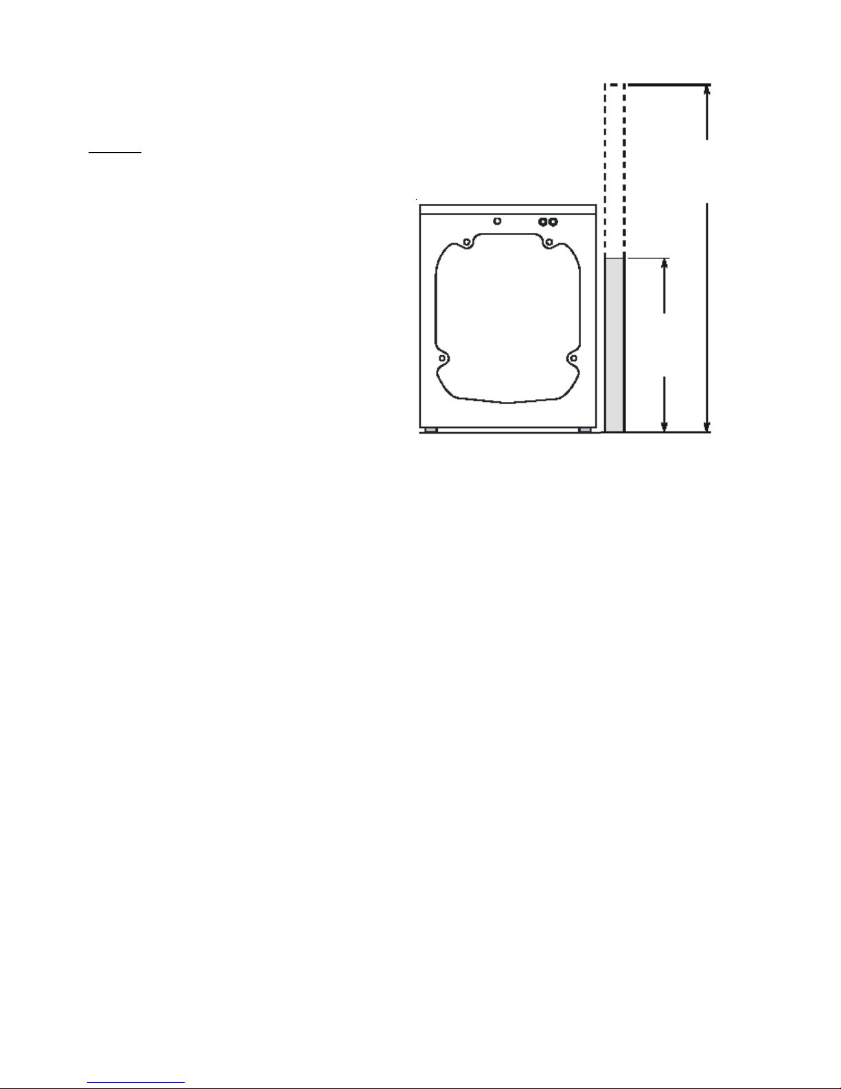
DRAIN REQUIREMENTS
1. Drain capable of eliminating 17 gals (64.3 L) per
minute.
2. A standpipe diameter of 1-1/4 in. (3.18 cm)
minimum.
96 in.
(244 cm)
Max
24 in
(61 cm)
Min
BACK
NOTE:
Drain hose attached to the washer can reach a 90 in.
(229 cm) high standpipe. For a higher standpipe, use
hose P/N 134369410 available from an authorized parts
distributor.
3. The standpipe height above the floor should be:
Minimum height: 24 in. (61 cm)
Maximum height: 96 in. (244 cm)
16
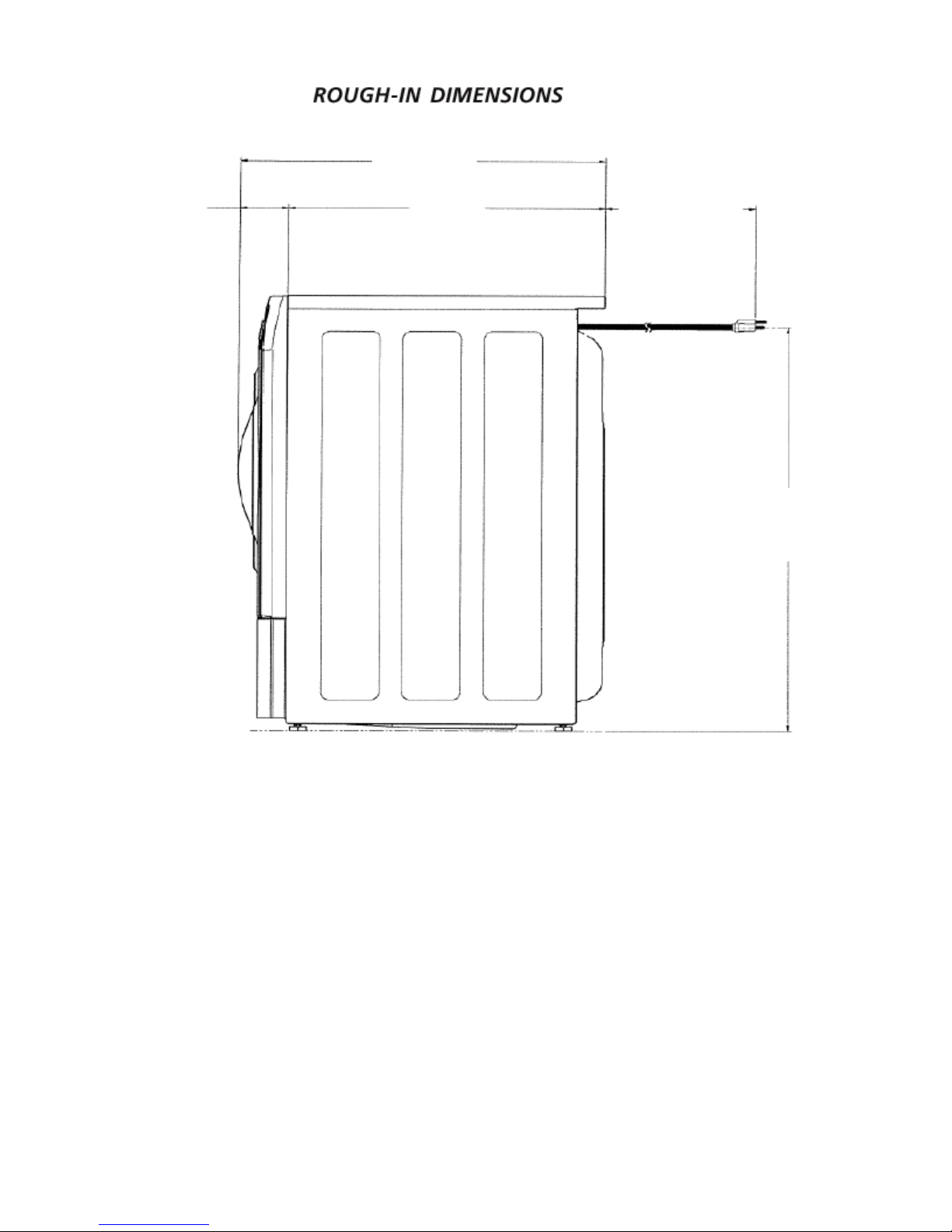
27.75”
(70.5)
3.75”
(9.5)
24”
(61)
60”
(152.4)
POWER CORD
33.40”
(84.8)
SIDE
17
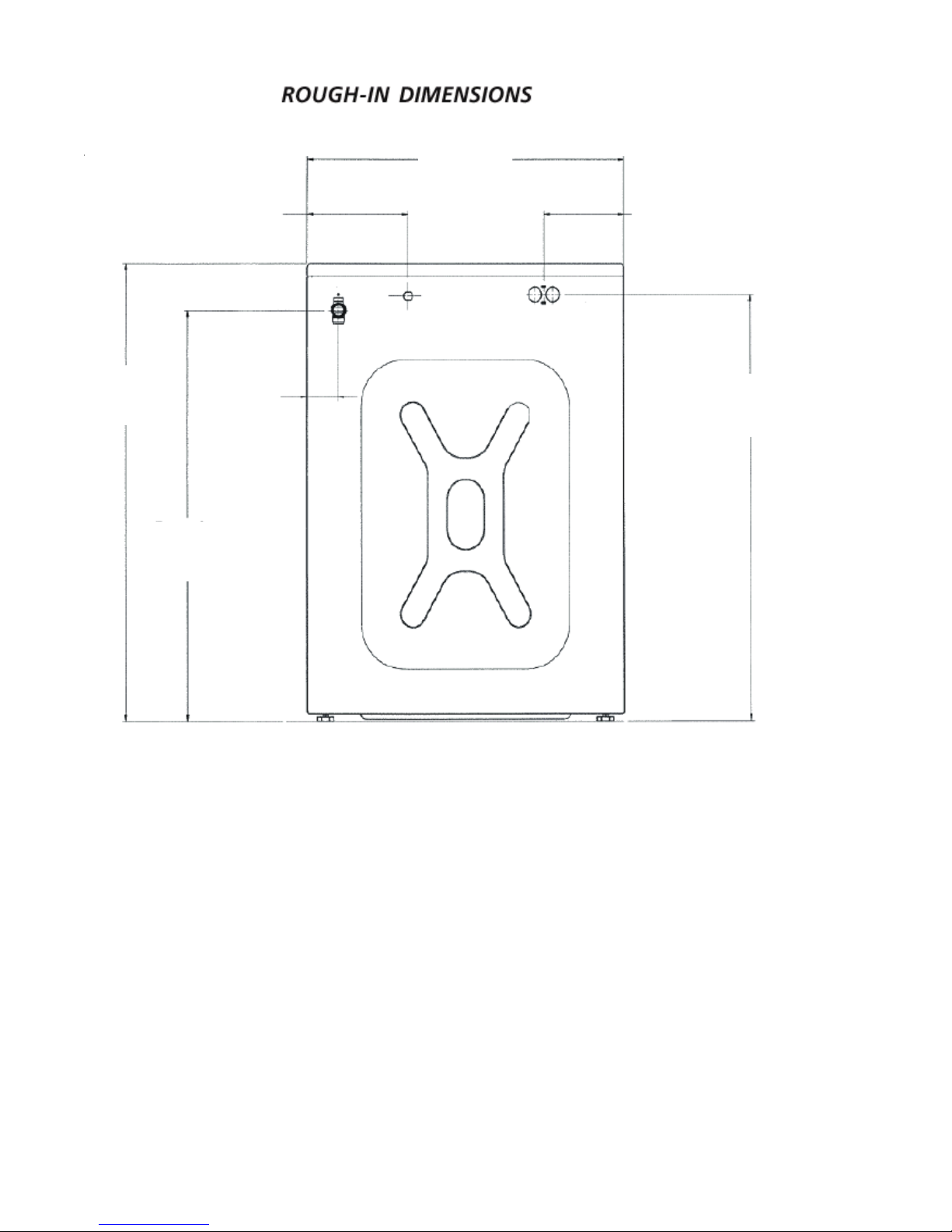
27”
(68.6)
36”
(91.3)
DRAIN
32.25”
(81.9)
8.5”
(21.6)
2.75”
(7)
6.75”
(17.1)
WA TER INLETS
33.5”
(85.1)
BACK
18
LOCA TION OF YOUR WASHER
DO NOT INST ALL YOUR W ASHER:
1. In an area exposed to dripping water or outside
weather conditions. The ambient temperature should
never be below 60 ° F (15.6 ° C) for proper washer
(detergent breakdown) operation.
2. In an area where it will come in contact with curtains
or drapes.
3. In an area (garage or garage-type building) where
gasoline of other flammables are kept or stored
(including automobiles).
4. On carpet. Floor MUST be solid with a maximum
slope of 1/2 in. per foot (1.27 cm per 30.5 cm). To
ensure vibration or movement does not occur,
reinforcement of the floor may be necessary .
IMPORT ANT
MINIMUM INSTALLA TION CLEARANCES
When installed in alcove or closet:
Sides, Rear = 0 in. (0 cm)
Top = 0 in. (0 cm)
When installed in closet: Front = 1 in. (2.54 cm)
Closet door ventilation required: 2 louvered openings
each 60 in 2 (387 cm 2 ), 3 in. (7.6 cm) from top and
bottom of door.
POWER CORD
REMOVE TWO
UPPER BOL TS,
‘P’ CLAMPS,
AND SPRINGS
REMOVE LOWER
BOL TS AND
WASHERS (2),
SCREWS (4),
AND BRACE
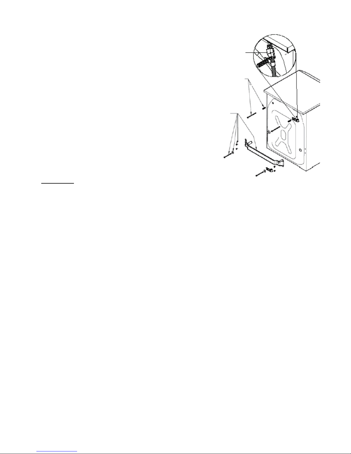
6. Remove the following from the back panel of the
washer:
4 packaging bolts,
2 packaging springs,
2 washers,
2 metal “P” clamps,
4 screws,
1 packaging brace.
7. Remove the 4 transport plugs from the literature
pack and install them in the corresponding holes
in the back panel of the washer.
UNPACKING
1. Cut the shipping carton along the dotted line along
the base of the unit.
2. While in the carton carefully lay the washer on its
back side.
3. Remove the styrofoam base.
4. Carefully return the washer to an upright position
and remove the carton.
5. Carefully move the washer to within 4 feet (122cm) of
the final location.
19
8. Remove the 4 small hole plugs from the literature
pack and install them in the side panel holes
vacated by the packaging brace.
9. Using the shipping posts, prop up the front of the
washer approximatley 2 inches to gain access to
the service panel screws.
10. Remove the 2 screws and remove the service panel.
REMOVE LEFT
AND RIGHT
FOAM BLOCKS
TWO SCREWS
UNDER P ANEL
1 1. Remove the two (2) styrofoam blocks located
under the drum (a yellow ribbon surrounds the items
to be removed). Lift up on the drum, tilt the base of
the foam blocks inwards toward the rear of the
washer until free, then pull them out.
12. Remove and discard the yellow ribbon from the front
of the washer.
13. Replace the service panel and screws.
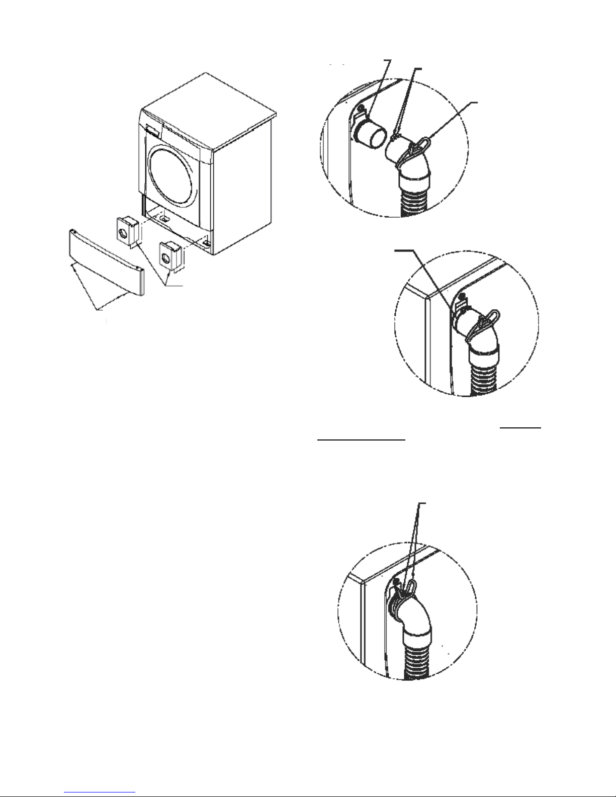
STOP RIB
PUSH HOSE
INTO COUPLER
TO STOP
3. Using pliers, squeeze the ears of the spring clamp
and position the clamp so the clamp ears align with
and contact the tabs on the drain hose. This assures
proper location of the clamp to prevent leaks.
DRAIN HOSE T AB
SPRING
CLAMP
PROVIDED
ON HOSE
NOTE: If the washer is to be transported at a later
date, the shipping support hardware must
be reinstalled to prevent shipping damage.
Drain Hose Installation
The drain hose is field installed to allow hose orientation
to the left or right, up or down depending on location of
the house drain. The hose is shipped in the washer tub
with the spring clamp on the coupler elbow and drain
hose hanger installed on the end of the hose.
1. Remove the drain hose from the tub of the washer.
2. Push the hose onto the drain coupler at the upper
left of the washer back panel until the hose contacts
the STOP RIB.
ALIGN SPRING
CLAMP EARS WITH
T ABS ON HOSE
20
T ABS
INSTALLATION
ORIENT HOSE
TO RIGHT,
LEFT , UP
OR DOWN
AS NEEDED
BEFORE
PLACING
CLAMP IN
POSITION
ALW A YS ALIGN CLAMP
EARS WITH T ABS
ON HOSE
4. Connect the inlet hose ends to the HOT and COLD
water faucets tightly by hand, then tighten another
2/3 turn with pliers. Turn the water on and check
for leaks.
NOTE: Use only new hoses.
5. Carefully move the washer to its final location.
NOTE: Do not use the dispenser drawer or door
to lift washer .
6. With the washer in its final position, place a level
on top of the washer. No rocking of the washer
should exist. Adjust the front leveling legs up or
down to ensure the washer is resting solid. Rear
leg adjustment is accessible through the front
service panel.
NOTE: Keep the leg extension at a minimum to
prevent excessive vibration. The farther out
the legs are extended the more the washer
will vibrate.
1. Run some water from the
hot and cold faucets to flush
the water lines and remove
particles that might clog up
the water valve screens.
2. Remove the inlet hoses and
rubber washers from the
plastic bag located in the
drum of the washer and
install the rubber washers in
each end of the inlet hoses.
3. Carefully connect the inlet hose (90° elbow end)
marked “HOT” to the outside “H” outlet of the water
valve. Tighten by hand, then tighten another 2/3 turn
with pliers. Carefully connect the other inlet hose
(90° elbow end) to the inside “C” outlet of the water
valve. Tighten by hand, then tighten another 2/3 turn
with pliers. Do not crossthread or over-tighten
these connections.
7. Place the hook end of the drain hose in the drain
opening. Secure the drain hose with the cable tie
(provided in the enclosure package) to the
standpipe, inlet hose, laundry tub, etc. so the hose
does not pull out from the force of the water.
Cable Tie
21
12. If your washer does not operate, please review the
“Avoid Service Checklist” in your Owner’s Guide
before calling for service.
13. Place these instructions in a location near the
washer for future reference.
NOTE: A wiring diagram and technical data sheet are
located in an envelope attached to the left hand
side panel on the inside of the washer .
REPLACEMENT PARTS
Cable Tie
Cable
Tie
If replacements parts are needed for your washer , call
Sears Parts and Service Toll Free Number 1-800-4MY -HOME (1-800-469-4663).
TM
Destroy the carton and plastic bags
after the washer is unpacked. Children might use them
for play. Cartons covered with rugs, bedspreads, or
plastic sheets can become airtight chambers causing
suffocation. Place all materials in a garbage container
or make materials inaccessible to children.
The instructions in this manual and all
other literature included with this washer are not meant
to cover every possible condition and situation that may
occur. Good safe practice and caution MUST be applied
when installing, operating and maintaining any
appliance.
Maximum benefits and enjoyment are achieved when
all the Safety and Operating instructions are
understood and practiced as a routine with your
laundering tasks.
8. Plug the power cord into a grounded outlet.
NOTE: Check to ensure the power is off at a
circuit breaker/fuse box before plugging
the power cord into an outlet.
9. Turn on the power at a circuit breaker/fuse box.
10. Read the Operating Instructions and Owner’s Guide
provided with the washer. They cont ain valuable and
helpful information that will save you time and money .
1 1. Run the washer through a complete cycle. Check
for water leaks and proper operation.
22
SECTION B - Washer & Dryer
Pedestal Installation Instructions
IMPORTANT: Read and save these
instructions.
This kit is intended to be installed
by persons having electrical and
mechanical training and a level of
knowledge considered acceptable
in the appliance repair trade.
Y our safety and the safety of others are very
important. Many important safety messages
are provided in these instructions and on
your appliance. Always read and obey all
safety messages.
WARN I NG
EXCESSIVE WEIGHT HAZARD
Two or more people may be required to move and
install the washer & dryer onto pedestals.
Failure to comply may cause back or other injury .
WASHER INSTALLATION
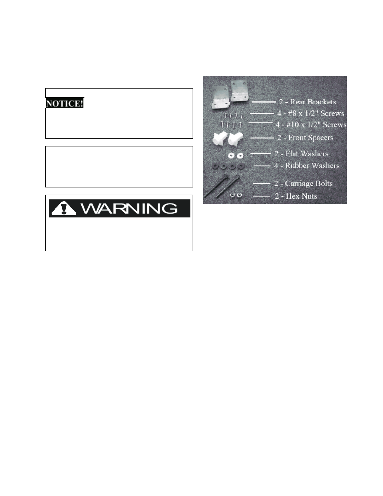
Washer Installation Kit
1. Remove the washer installation hardware from
the plastic bag.
2. Attach the rear brackets to the pedestal with four
#8 screws (2 per bracket).
T ools needed:
level
7/16” open end wrench or ratchet &
socket
9/16” open end wrench
adjustable wrench
#2 Phillips screwdriver
flat blade screwdriver
23

3. Remove the front service panel from the washer.
Using two or more people, carefully lift the
washer onto the pedestal and set flush against
the rear brackets as shown.
NOTE: If washer was previously installed,
disconnect power cord, remove inlet hoses
from water faucets and tape the drain hose to
the top of the washer to eliminate excess
water on the floor. Also, make sure the
leveling legs are adjusted fully into the
washing machine.
6. Insert the bolt/spacer assembly up through the
pedestal with the front spacer positioned in the
square hole of the pedestal and the bolt coming
through the slotted hole in the washing machine
base.
7. Install a rubber washer, flat washer and hex nut
onto the carriage bolt. Tighten the hex nut.
4. Align the sides of the washer with the sides of
the pedestal and attach the washer to the rear
brackets using four #10 screws (2 per bracket).
5. Open the drawer of the pedestal; assemble a
carriage bolt through a front spacer and rubber washer.
24

8. Repeat installation of bolt/spacer assembly for the
other side.
9. After closing the pedestal drawer , carefully move the
washer/pedestal assembly into
position. NOTE: Because of the increased weight
caused by the addition of the pedestal, two or
more people may be required.
DRYER INSTALLATION
Dryer Installation Kit
1. Remove the dryer installation hardware from the
plastic bag.
2. Attach the rear brackets to the pedestal with four
#8 screws (2 per bracket).
NOTE: The washer/pedestal assembly MUST be
on a solid floor and level for proper operation.
After leveling the washer/pedestal assembly,
adjust the lock nut on each leveling leg against
the pedestal base and tighten with a wrench.
Keep the leg extension at a minimum to prevent
excessive vibration.
10. Refer to the installation instructions that came
with the washer to properly complete electrical,
water, and drain connections. If questions arise,
please refer to the Owner’s Guide that came with the
washer for contact information.
25

3. Attach the front brackets to the pedestal with
four #8 screws (2 per bracket).
NOTE: If dryer was previously installed,
disconnect power cord and vent hose.
Also, make sure the leveling legs are
adjusted fully into the dryer.
5. Set the dryer down onto the pedestal making sure
the service panel bracket on the dryer is behind the
front brackets of the pedestal.
4. Using two or more people, carefully lift the dryer onto
the pedestal, tilting the dryer back slightly to engage
the slots in the rear of the dryer with the tabs of the
rear brackets on the pedestal.
26
6. With the pedestal drawer open for better access,
install the two #10 screws through the front
brackets in the pedestal into the service panel
bracket of the dryer.
7. After closing the pedestal drawer , carefully move the
dryer/pedestal assembly into position.
NOTE: Because of the increased weight
caused by the addition of the pedestal,
two or more people may be required.
8. Refer to the installation instructions that came with
WARRANTY
Full One Y ear W arranty on Mechanical Part s
NOTE: The dryer/pedestal assembly
on a solid floor and level for proper
operation. After leveling the
dryer/pedestal assembly, adjust the lock
nut on each leveling leg against the
pedestal base and tighten with a wrench.
Keep the leg extension at a minimum to
prevent excessive vibration.
the dryer to properly complete electrical and venting
connections. If questions arise, please refer to the
Owner’s Guide that came with the dryer for contact
information.
MUST be
Sample warranty - always check
warranty with product
For one year from date of purchase, when this pedestal is installed with the listed washer or dryer (see
owners manual for specific model) and operated according to the information in the Use and Care Guide,
Operating Instructions and Installation Instructions, the supplier will replace any of its mechanical parts if
they are defective in workmanship or material. Keep your bill of sale. The date of the bill establishes the
warranty period should parts be required. This written warranty gives you specific rights. Y ou may also have
other rights which vary from state to state.
Warranty Restriction
If the pedestal is used for any other purpose than private family use or used with any product that requires
modification for installation, the warranty is null and void.
Warranty Part s
Warranty parts are available by contacting the supplier where the pedestal was purchased or refer to the
Use and Care Guide that came with the washer or dryer that is installed on the pedestal for contact
information.
27
SECTION C - OPERATING
INSTRUCTIONS
• Any water remaining in the dispenser at the end of
the cycle is a result of siphoning action and part of
normal operation.
Before Operating Y our Washer
Read your washer Owner’s Guide. It has important safety
and warranty information. It also has many suggestions
for best washing results.
To reduce the risk of fire, electric
shock or injury to persons, read the IMPORTANT
SAFETY INSTRUCTIONS in your washer Owner’s Guide
before operating this appliance.
Operating Steps
Read and follow “Washing Procedures” in your Owner’s
Guide. It provides detailed information for preparing the
wash load and choosing control settings to ensure best
washing results.
1. Sort laundry into loads that can be washed together.
2. Prepare items for washing.
3. Pretreat stains and heavy soil.
4. Add laundry load to the wash drum.
5. Add laundry product s to the dispenser.
6. Select the appropriate cycle and temperature for the
load.
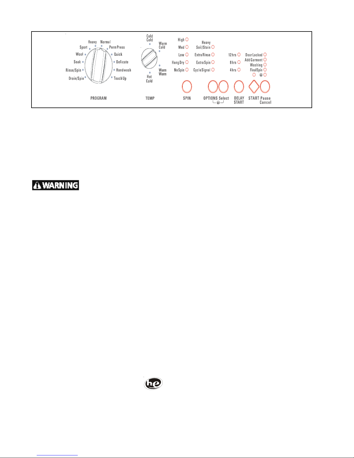
• Turn the PROGRAM knob to select the cycle.
• Turn the TEMP knob to select the wash and rinse
temperatures.
• If the water temperature combination is not
appropriate for that cycle, the status lights will blink
and the signal will beep 3 times.
7. The suitable final spin speed and options for that cycle
will automatically be displayed.
• T o change the final spin speed, press SPIN until the
indicator for the desired selection is lighted.
• T o select or delete an option, press OPTIONS, then
SELECT . The indicator light will stop blinking when
the option has been selected. It will not light if the
option is not available for that cycle.
• Adjustments to the cycle will be remembered each
time that cycle is selected in the future.
• See “Washer Settings Chart” chart for factory
settings.
• Detergent, bleach and fabric softener will be dispensed
at the proper time in the cycle.
• Slide saftey latch to the right to open the dispenser
drawer.
• Add the recommended amount of a high efficiency
detergent to the detergent compartment.
• If desired, add liquid chlorine bleach and liquid fabric
softener to the appropriate compartments.
• Slowly close dispenser drawer. The washer will not
operate with the drawer open.
Note: To provide the best care for your laundry
items, not every temperature, speed and
option is available with every cycle.
8. Select DELA Y START to delay the beginning of the
cycle for 4, 8 or 12 hours.
9. Start the washer .
• Close the door and press START. The washer will not
operate with the door open.
• As a safety measure, the door will automatically lock
during the entire wash cycle and the DOOR LOCK
indicator will be lighted.
28
 Loading...