

Page 1
INSTALLATION MANUAL
MODULAR REFRIGERATOR
CONNECTION KIT
WRB5004SA, WRB5004WA,
WFB4204SA, WFB4204WA
Page 2
ENVIRONMENTAL TIPS
WARNING
WARNING
WARNING
WARNING
TIPS & INFORMATION
ENVIRONMENTAL TIPS
CONTENTSCONGRATULATIONS
Congratulations and thank you for choosing our
connection kit. Before you install the connection kit, we
recommend that you read through the entire installation
manual.
To avoid the risks that are always present when you install
an electrical appliance, it is important that the kit and
appliance is installed correctly. Please read the safety
instructions in this installation manual as well as the
appliance’s user manual to carefully to avoid misuse
and hazards.
We recommend that you keep this instruction booklet
for future reference and pass it on to any future owners.
After unpacking the connection kit, please check it is not
damaged. If in doubt, do not use the connection kit but
contact your local Customer Care Centre.
Please ensure you read the instruction manual fully
before you call for service, or a full service fee could be
applicable.
Please read the user manual carefully and store in a
handy place for later reference. The symbols you will see
in this booklet have these meanings:
WARNING
This symbol indicates information concerning your
personal safety
CAUTION
This symbol indicates information on how to avoid
damaging the appliance
General warnings.................................................................................3
Connection kit items ....................................................................... 4
Before you begin ................................................................................5
Connection kit contents ................................................................ 6
Installation ..............................................................................................7
Adjusting door alignment .............................................................. 9
Information on disposal for users
ENVIRONMENT
• Remove and discard any packaging material before
using this accessory. Most of the packaging materials
are recyclable. Please dispose of those materials
through your local recycling depot or by placing
them in the appropriate collection containers.
WARNING
Risk of suffocation, injury or permanent disability.
• This accessory is not intended for use by persons
(including children) with reduced physical, sensory
or mental capabilities, or lack of experience and
knowledge, unless they have been given supervision
or instructions concerning the use of the appliance by
a person responsible for their safety.
• This accessory may contain small parts that are a
choking hazard. Not suitable for children under
3 years of age
TIPS AND INFORMATION
This symbol indicates tips and information about use of
the appliance
ENVIRONMENT
This symbol indicates tips and information about
economical and ecological use of the appliance
CAUTION
Safety points before using your appliance.
• Do not use or place the accessory near the edge
of the table or counter, near hot gas, stove, electric
burner or heated oven.
• This accessory is for indoor use only.
• This accessory is intended for domestic use only.
Electrolux will not accept any liability for possible
damage caused by improper or incorrect use.
• When cleaning, use only a soft cloth with an
unscented mild soap and lukewarm water.
• Never use hot water, solvents, commercial kitchen
cleaners, aerosol cleaners, metal polishes, caustic or
abrasive cleaners, or scourers to clean the accessory,
as they may damage it. Many commercially available
cleaning products and detergents contain solvents
that will damage your accessory.
• Care should be taken to correctly align the handle
to the refrigerator. Once assembled to the door the
handle can not be removed.
2 CONTENTS
Page 3

GENERAL WARNINGS
BEFORE YOU BEGIN
Please read the user manual carefully and store in a handy
place for later reference. Pass the user manual on to
possible new owners of the appliance.
NOTE: Please refer to your Appliance User Manual for
warnings relating to the appliance.
• Thoroughly inspect cabinets for any signs of damage
before commencing installation.
• If any damage is identified please contact
Electrolux Service.
• Check refrigerator recess dimensions and ensure that
they provide at least the minimum clearance at the back,
side and top as recommended on page 4.
• The floor where the refrigerator is to be placed must
be level, otherwise you will not be able to install your
refrigerator properly.
• Ensure that the floor and surrounding cupboards are
adequately protected from damage during unpacking
and throughout the installation process.
• Ensure that two adequate and accessible powerpoints
are installed inside the refrigerator recess before
installing and connecting your appliances. These
powerpoints should also be readily accessible after
fridge installation is completed.
• Do not use extension leads or power board or double
adapter under any circumstances as it may lead to
electric shock and / or fire. Seek assistance of a licensed
electrician if required.
• Unpack the connection kit and check for completeness
by referring to the “Connection kit package contents”
section.
NOTE: Due to size and weight of the cabinets as well as
complexity of the task ensure that installation is attempted
with at least two able-bodied persons. You are strongly
urged to consider hiring Electrolux Service to do the
installation.
3GENERAL WARNINGS
Page 4
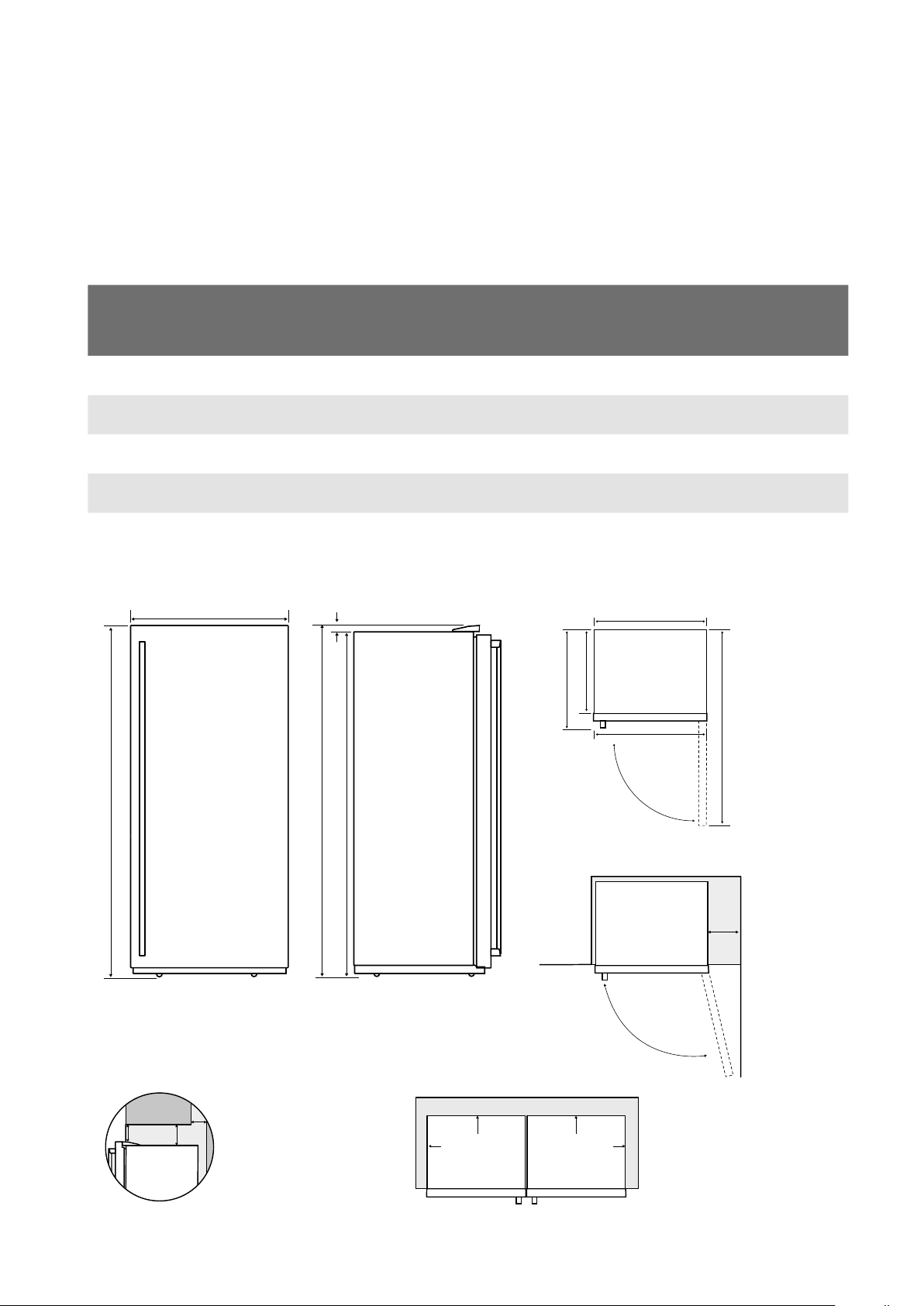
CONNECTION KIT ITEMS
Please note:
Doors are designed
to sit proud of
cabinetry (not flush).
50mm
30mm
30mm
CABINET
DOOR
Minimum
recommended
airspace
When positioned
in a cor
spacing of at
least 400mm on
the hinge side
will allow the
doors to open
enough to
enable the
removal of bins
and shelves.
Front face
of bench
aligned to
front corner
edge of
cabinet.
400mm
D1
D2
W1
W
D
90°
This connection kit is designed for use on single door
refrigerators and freezers whose total body height is 1725 mm.
The model numbers and overall dimensions of individual
products are:
MODEL DESCRIPTION
WRB5004SA-X 500L Single Door,
Refrigerator
WRB5004WA-X 500L Single Door,
Refrigerator
WFB4204SA-X 420L Single Door,
Freezer
WFB4204WA-X 420L Single Door,
Freezer
All measurements are in millimeters.
Single cabinet dimensions
W 22mm
H H2
MAX
DOOR
HEIGHT
(H)
CABINET
HEIGHT
(H1)
TOTAL
HEIGHT
(H2)
DOOR
WIDTH
(W)
CABINET
WIDTH
(W1)
TOTAL
DEPTH
(D)
TOTAL
DEPTH
(D1)
1725 1705 1725 699 693 773 641 1360
1725 1705 1725 699 693 773 641 1360
1725 1705 1725 699 693 773 641 1360
1725 1705 1725 699 693 773 641 1360
W1
D
D1
D2
H1
90˚
W
When
400mm
positioned
in a corner area,
spacing of at
least 400mm
on the hinge
side will allow
the doors to
open enough to
enable the
removal of bins
and shelves.
Front face
of bench
aligned to
front corner
edge of
cabinet.
DEPTH
DOOR
OPEN
(D1)
Minimum Recommended Airspaces
(Rear gap)
(y) (x)
4 KIT ITEMS
If you do not have
a cupboard with
a rear gap, the
recommended
clearance area on
top increases from
50mm to 90mm (x)
and from 32mm to
72mm (y).
30mm
50mm
Minimum
recommended
airspace
Cabinet
Door
50mm
30mm
Minimum
recommended
airspace
Cabinet
Door
Please note:
Doors are
designed to
30mm
sit proud of
cabinetry
(not flush).
Page 5

50mm
30mm
CABINET
DOOR
Minimum
recommended
airspace
Please note:
Doors are designed
to sit proud of
cabinetry (not flush).
50mm
30mm
CABINET
DOOR
Minimum
recommended
airspace
Wa
63mm
H1
D1
D
Wa
63mm
Wa
JOINED DIMENSIONS
Wb
D
D1
H
Joined cabinet dimensions:
H1
INDIVIDUAL CABINET WIDTHS
(W1)
model 1 model 2 (H1) (H) (Wa) (Wb) (D) (D1)
693 693 1705 1725 1407 1419 773 641
693 790 1705 1725 1504 1516 773 641
All measurements are in millimeters.
CABINET
HEIGHT
MAX DOOR
HEIGHT
JOINED
CABINET
WIDTH
JOINED
DOOR WIDTH
MAX TOTAL
DEPTH
MAX CABINET
DEPTH
5BEFORE YOU BEGIN
Page 6

CONNECTION KIT PACKAGE CONTENTS
ITEM DESCRIPTION QT Y. ANC
1
2
Top-front bracket
Self tapping screw
1
1
Grey
A03972801
1460583
White
A03972802
1460583
3
4
5
6
10
11
12
Bottom rear bracket 1 A03979601
Replacement screw ST4.2
x 6mm for the bottom rear
bracket
Replacement foot base
with M4 threaded holes
Bottom front bracket
assembly
Centre cover 1 Grey
Foot Assembly Left
Foot Assembly Right
Mounting M5 x 12 bolts M5
nuts set
2 A04064601
2 A02102702
1 Grey
A03973401
A03973701
2
2
8
8
A02816701
A02816702
A04064701
A04797101
White
A03973402
White
A03973702
13
14
6 PACKAGE CONTENTS
Protective foam pads with
peelable adhesive tape
Protective cardboard 1 A04064701
4 A04064701
A04797101
A04797101
Page 7

300mm
100mm
300mm
100mm
INSTALLATION
Required Tools
• 3mm Allen key
• Phillips head screwdriver
• 7mm socket wrench screwdriver
Preliminary Operations – General Preparation
• Before starting to bring the appliances together, in
order to protect the sides from possible damage
during the installation process, attach the four
disposable protective foam pads at the facing side
corners of one of the appliances (foam should be
applied to the handle side of the cabinet as shown
with approximately 100mm from the front or back
and 300mm from the top or bottom).
100mm
300mm
100mm
300mm
Fitting rear levelling feet
NOTE: Two people may be required for this operation
A set of adjustable back feet is provided with the kit.
These parts are usually needed only in the case of a
particularly
uneven floor and when height adjustments in phase 1.2.1
proved unsuccessful.
• Temporarily remove the screws holding the
evaporator tray.
• Temporarily remove the 2 cabinet screws that will
hold the foot.
• Pre-assemble the two nuts on the foot.
• While one operator is lifting the appliance the other
can assemble the foot.
• Pull the appliances together.
• Adjust the front feet of the appliances to the same
height and alignment.
Replace Foot Bases
NOTE: Two people may be required for this operation
• Remove the two front feet that will meet in the
middle then remove the factory fitted base, discard
and replace with the foot base part (item 5) supplied
in the kit ensuring that the M4 threaded hole is facing
the front and is nearest the outside edge of the
cabinet.
Ensure the hole is nearest
the outside edge of the
cabinet
Remove the
factory
fitted
base
Select the supplied
base (item 5) in
the kit
Perform these steps
on both cabinets
Fit to cabinet
• Assemble right foot using the two cabinet screws
that have previously been removed and the two bolts
that come with the foot.
• Repeat the process for the other side.
7INSTALLATION
Page 8

Extract the
tensioner
Extract the
tensioner
Tighten all
screws
Extract the
tensioner
Fit bottom first
INSTALLATION
Joining the Appliances
Your appliances are delivered with hole covers that cover
the screw holes. These holes are located on the top of the
cabinet, opposite from the door hinge. Carefully remove
these covers, care must be taken to avoid damaging the
appliances.
Carefully pull the appliances together adjacent to the final
installation location, then adjust the front and rear feet to
the same height.
Remove covers
Top-front and bottom-rear bracket installation
Install the top-front bracket
• Place the protective cardboard between the bracket
and the cabinets.
• Assemble the top-front bracket, fit the screws in
place, but do not tighten them yet leave the screws
loose.
Do not tighten
Bottom-front bracket installation
– Position the bottom-front bracket
• Position the bottom-front bracket between the two
cabinets.
• Fasten with the two M4 screws using a phillips head
screwdriver.
• Extract the tensioner.
Extract the
tensioner
Fit the centre cover
• Push the centre cover between the two cabinets
• Engage the bottom end of the centre cover into the
tensioner of the bottom-front bracket.
• Lift the top-front bracket (screws should be loose
enough) and slide the centre cover underneath.
• Tighten the screws in the top-front bracket.
• Adjust the tensioner screw as required.
• Fasten the centre cover to the top-front bracket by
means of the provided self-tapping screw
Install the rear-bottom bracket
• Unscrew the 2 central-upper compressor cover
fasteners.
• Remove 2 screws.
• Assemble the rear-bottom bracket using the
replacement screws provided.
8 INSTALLATION
Fit bottom first
Lift top-front
bracket
Slide centre
cover under
Page 9

ADJUSTING DOOR ALIGNMENT
Tighten all
screws
Extract the
tensioner
Tighten all
screws
Self tapping
screw
Extract the
tensioner
Fit bottom first
Tighten all
screws
Self tapping
screw
Extract the
tensioner
Tension screw
Tighten all the
screws
Self tapping screw
To complete installation of your joined appliances it may
be necessary to slightly adjust door alignment on the
individual appliance. This process is illustrated in the
following section.
1. With the door open, remove the hinge cover by
simultaneously pulling the cover away and up from
the hinge. This action will release the clip that is
retaining the cover to the hinge.
Small plastic clip is located here. With the door
open, pull the cover outward while simultaneously
pulling up in order to release the hinge cover.
2. Slightly loosen the three screws retaining the hinge
to the cabinet. This will allow for slight movement of
the cabinet door. Have the assistant hold the door in
desired position and fully secure top hinge fasteners,
inspect the alignment and if satisfied clip the hinge
cover back onto the top hinge.
Loosening the top hinge fasteners will allow the
top hinge to be slightly rotated thus adjusting the
gap between doors.
9DOOR ALIGNMENT
Page 10

NOTES
10 NOTES
Page 11

NOTES
11NOTES
Page 12

For more information on all Westinghouse
appliances, or for dimension and installation
information, call into your retailer, phone or email
our customer care team or visit our website:
AUSTRALIA
phone: 1300 363 640
fax: 1800 350 067
email: customercare@electrolux.com.au
web: westinghouse.com.au
NEW ZEALAND
phone: 0800 436 245
fax: 0800 225 088
email: customercare@electrolux.co.nz
web: westinghouse.co.nz
TOP SERVICE
Top Service encompasses the after sales service
provided by The Electrolux Group to consumers
including delivery, home service and spare parts.
and WESTINGHOUSE are trademarks of Westinghouse Electric Corporation.
Used under license. All Rights Reserved.
P/No. A04767002
© 2016 Electrolux Home Products Pty Ltd.
ABN 51 004 762 341
WMAN_WFRI_CONN_KIT_Sep16
 Loading...