

Electrolux WLGWDAOOOO, 584166, WLGWAAOOOO, WLGWDFOOOO, 9CHG584163 User Manual
...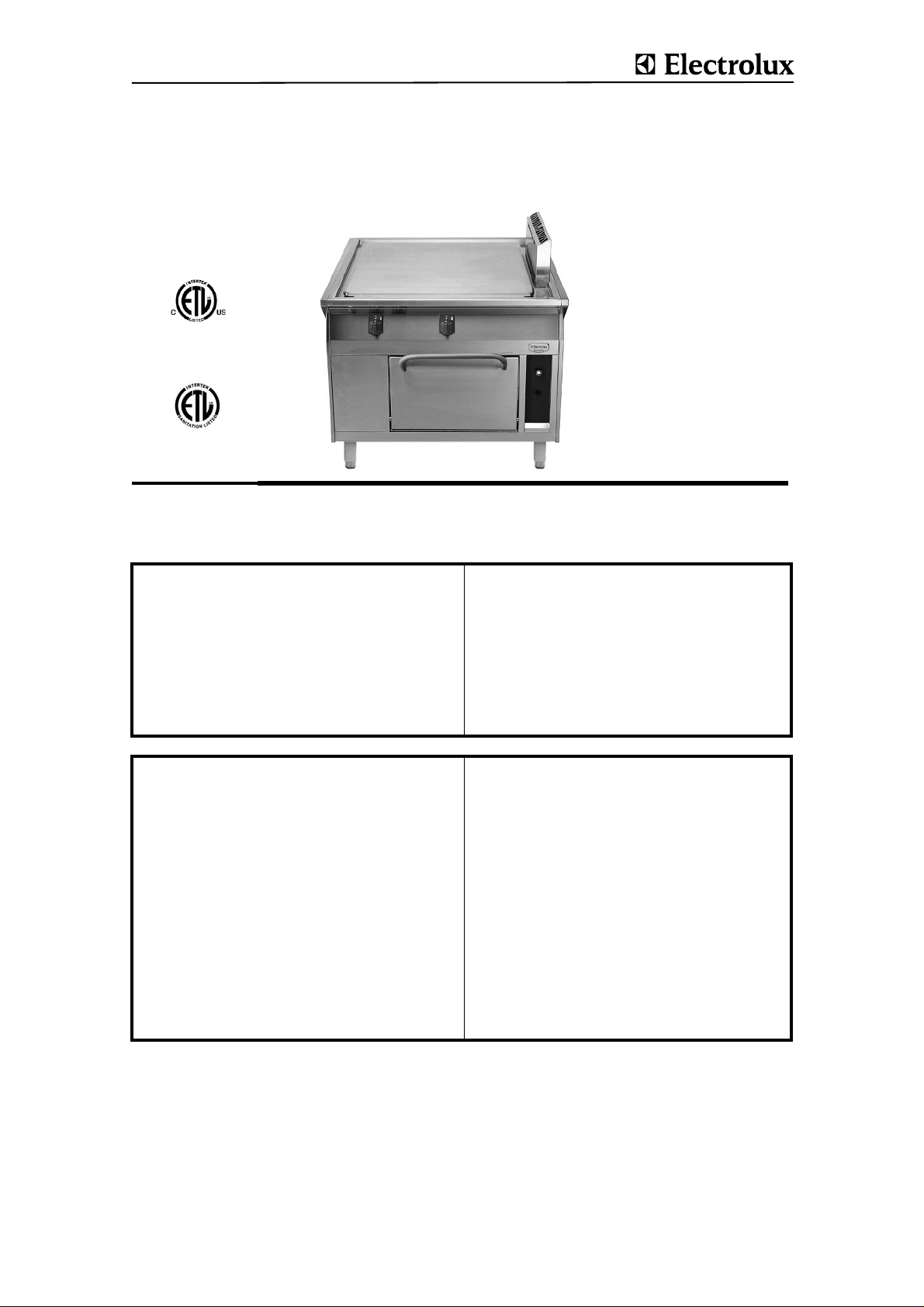
thermaline S90
SOLID TOP GAS COOKERS
US INSTALLATION- AND OPERATING INSTRUCTIONS page 3
FR INSTRUCTIONS D’INSTALLATION ET D’EMPLOI page 13
FOR YOUR SAFETY
Do not store or use gasoline or
other flammable vapors or liquids
-
FOURNEAUX À PLAQUE COUP DE FEU, GAZ
Doc.
62.9534.01_UL
Edition 1
01.2006
POUR VOTRE SÉCURITÉ
Ne déposez pas ou n'employez
pas l'essence ou d'autres vapeurs
in the vicinity of this or any other
appliance.
ou liquides inflammables à pro-
ximité de ceci ou d'aucun autre
appareil.
WARNING
Improper installation, adjustment, alteration, service or
maintenance can cause property
damage, injury or death. Read the
installation, operating and
maintenance instructions thoroughly before installing or servicing
this equipment.
AVERTISSEMENT
L'installation inexacte, l'ajuste-
ment, le changement, le service
ou l'entretien peuvent causer des
blessures matériels, des domma-
ges ou la mort. Lisez les instruc-
tions d'installation, d'opération et
d'entretien complètement avant
d'installer ou entretenir cet
équipement.
INSTRUCTION
Post in a prominent location instructions to be followed if the user smells gas. Consult
the local gas supplier to obtain the information.
Présentez dans des instructions en avant d'un endroit d'être suivi si l'utilisateur sent le
gaz. Consultez le fournisseur local de gaz pour obtenir l'information.
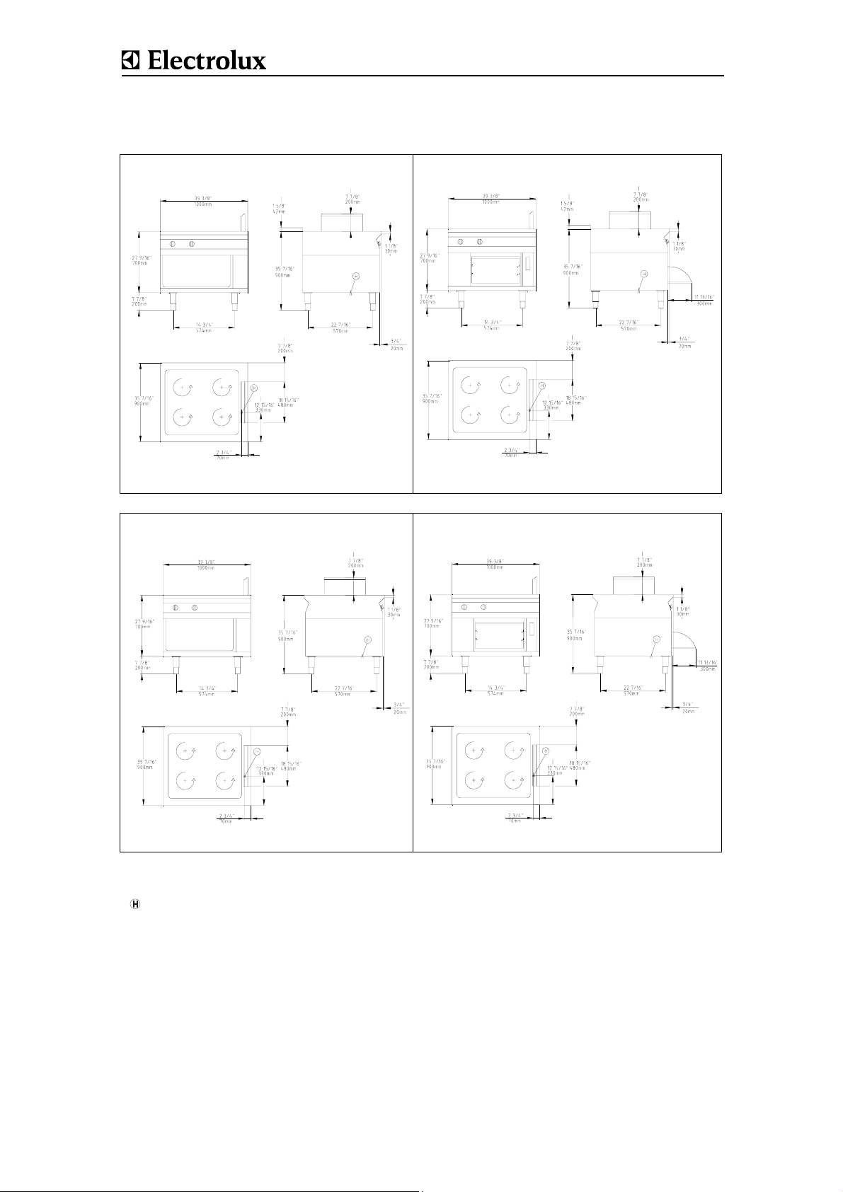
Against wall - contre une paroi
Free standing - isolé
Connections - Raccordement
Gas - Gaz
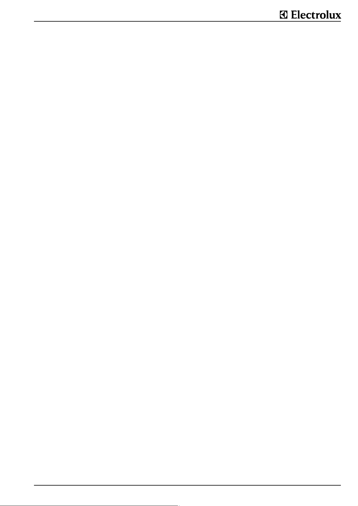
Fig.1 INSTALLATION DRAWINGS - PLANS D'INSTALLATION
Doc. 62.9534.01_UL
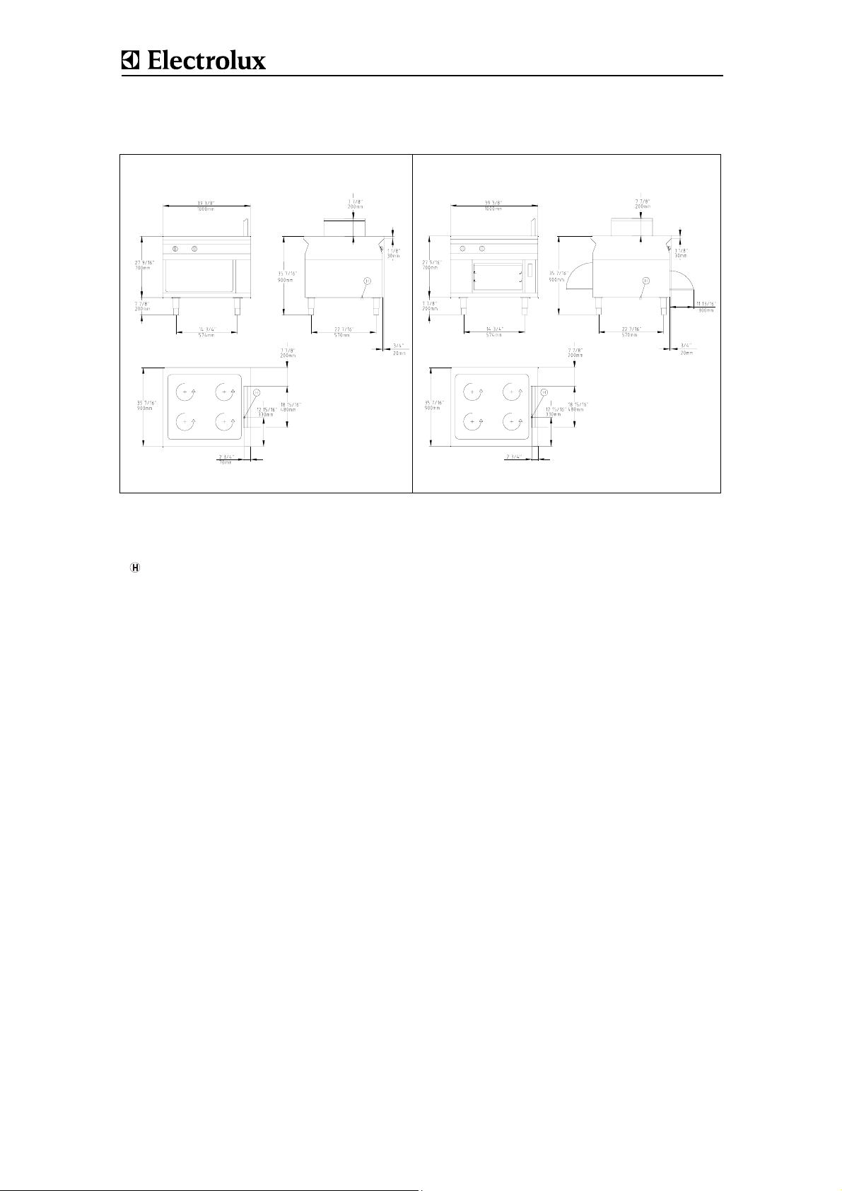
Free standing - isolé
Base operated from both sides - base ulilisable des deux côtés
Connections - Raccordement
Gas - Gaz
Fig.1 INSTALLATION DRAWINGS - PLANS D'INSTALLATION
Doc. 62.9534.01_UL

Doc. 62.9534.01_UL
CONTENTS
I. GENERAL INFORMATION................................................................................................. 3
II. INSTALLATION INSTRUCTIONS....................................................................................... 5
III. OPERATING INSTRUCTIONS............................................................................................ 9
SOMMAIRE
IV. INSTRUCTIONS GÉNÉRALES......................................................................................... 13
V. INSTRUCTIONS RELATIVES À L'INSTALLATION......................................................... 15
VI. INSTRUCTIONS DE FONCTIONNEMENT....................................................................... 19
APPENDIX
VII. Table of nozzle - Tableau de gigleur
62.9534.01_UL Page 1

Page 2 62.9534.01_UL
I . GENERAL INFORMATION
GENERAL INFORMATION
1. INSTRUCTIONS FOR SAFETY AND USE
1.1 INSTALLATION AND INITIAL OPERATION
S The installation, adjustment and initial opera-
tion of the appliance must be carried out
according to the manufacturer's instructions
and may only be done by an authorised specialist.
S Installations for the supply of electricity and
gas must be carried out by approved specialists in compliance with specific national and
local regulations. They bear the responsibility.
S The installation must conform with local
codes, or in the absence of local codes, with
the National Fuel Gas Code, ANSI
Z223.1/NFPA 54, or the Natural Gas and
Propane Installation Code, CSA B1 49.1.
S The appliance and its individual shutoff valve
must be disconnected from the gas supply
piping system during any pressure testing of
that system at pressures in excess of 1/2 psi
(3.5 kPA)
S The appliance must be isolated from the gas
supply piping system by closing its individual
manual shutoff valve during any pressure
testing of the gas supply piiping system at
test pressures equal to or less than 1/2 psi
(3.5 kPA)
S The appliance must not be placed in opera-
tion until the user has become familiar with its
operation. The operating instructions and the
related safety precautions must be followed
precisely. Follow strictly the attention and
warning label indications on the appliances
1.2 OPERATOR'S OBLIGATIONS
S The manager is responsible for ensuring that
all components relevant to safety are in perfect working order at all times. The operating
condition of these components must be
examined by an authorised specialist at least
once a year and any defects remedied if
required.
S The operator of this appliance is responsible
for total observation of the national regulations concerning operating safety.
S Remain the manual for future reference.
S The roasting and baking oven must under no
circumstances (not even at the low setting)
be operated with a slightly opened door,
since the high temperatures can damage the
control knobs and gas valve.
S When putting oil, fat, water or ingredients in
the preheated hot frying pan, they may spit -
danger of burning!
S
Overheated oil can ignite spontaneously. Never
use water to extinguish burning oil, but smother
the flames with the lid or a damp cloth.
S The escape of burnable gases represents a
fire and explosion hazard. Action in the case
of a gas leak and a smell of gas:
- No smoking, no fire
- Do not operate electric switches or bells.
- Do not operate the piezo igniter
- Close gas cylinder valves and the main
gas valve on the appliance.
- Ventilate the room thoroughly
- Place the leaking gas cylinders upright in
the open with valves closed.
S The waste-gas outlets of the fryer become
hot. Avoid touching them.
S The waste-gas outlets of the fryer are not to
be covered by any objects.
S Spraying the appliance or parts of it with a
high-pressure cleaning device may cause
malfunctions and is not to be done.
S Keep the appliance area free and clear from
combustibles
S Do not obstruct the flow of combustion and
ventilation air.
S To avoid damage to the appliance, do not let
water flow from the mixer tap onto the cooking plates.
S Devices on wheels set up in block configura-
tion must be checked before each start-up
whether the potential equalization is connected with the neighbour equipment. The
connection may be done only by authorized
technical personnel.
S Appliances on wheels must be fastened to
the building.
1.3 USE AS PRESCRIBED
S Closed containers (jars, cans, bottles, tubes,
etc.) must not be heated owing to the danger
of bursting and injuries.
1.4 SAFETY-CONSCIOUS WORKING
S
Touching the hot cooking zones can cause
burns.
S Keep a minimum distance of 16 inch (40 cm)
to the appliance, in order to a safety opening
of the oven door.
S Do not touch the curves of the oven door
handle, it can be hot. Use always the straight
part.
62.9534.01_UL Page 3
GENERAL INFORMATION
1.5 AFTER-SALES SERVICE AND REPAIR
S In the event of a permanent fault which inter-
feres with operation, the appliance must be
switched off and disconnected from the
power supply.
S To perform maintenance and repairs contact
the factory, the factory representative or a
local service company.
S Repair, maintenance work and other adjust-
ments are only to be carried out by an
authorised specialist. The valid local and
national regulations must be observed. This
applies especially to burners, ignition, safety
and control elements. Parts requiring
replacement are only to be replaced by original spare parts. Periodic tests for gas leaks
must be carried out. A service contract is
therefore recommended.
S Cleaning and maintenance must be done
only when the heating surfaces are cold. Do
not use inflammable liquids to clean the
appliance.
S An obligatory service check is required
annually.
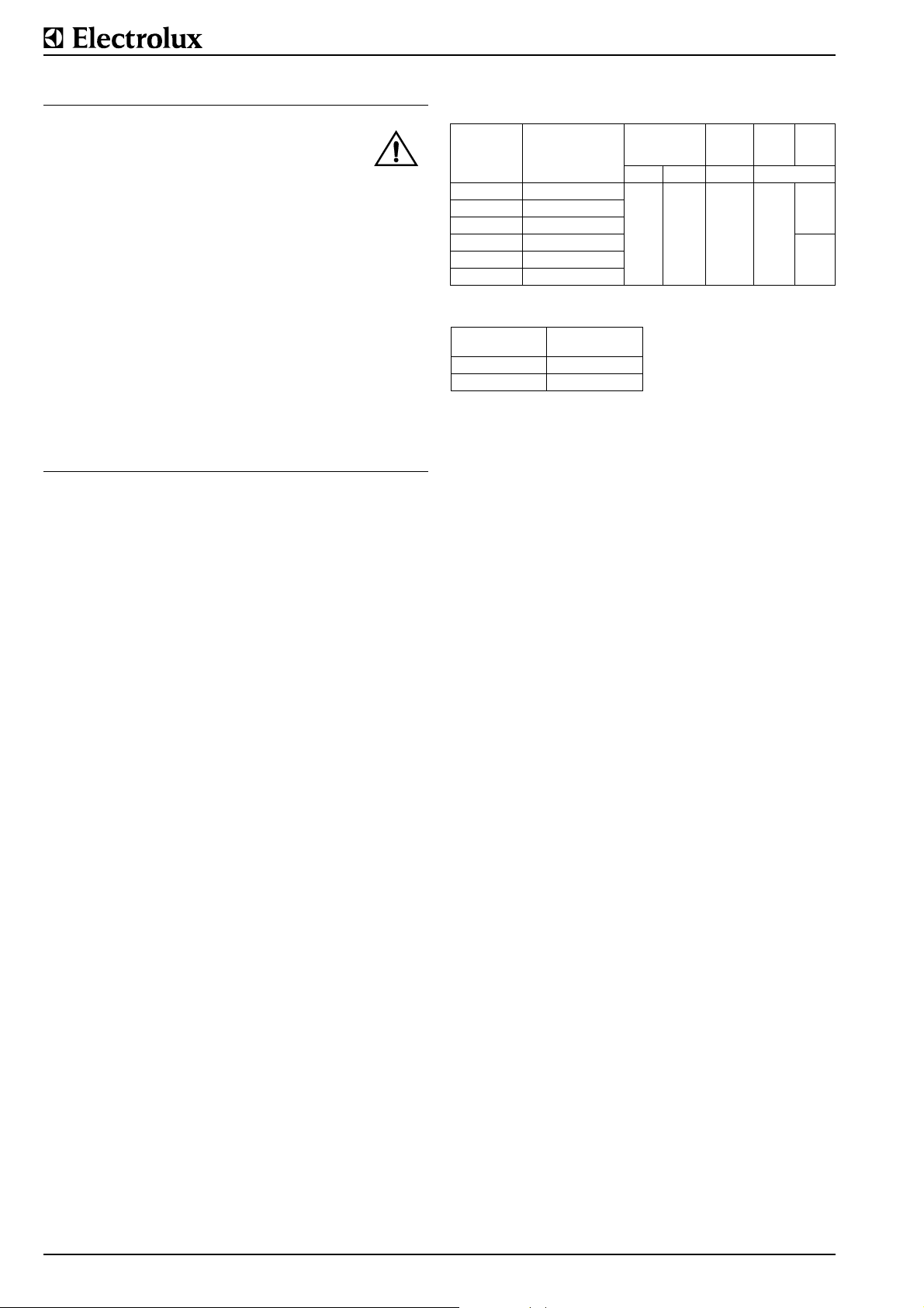
2. TECHNICAL DATADATA
PNC Appli-
ances
9CHG584158
9CHG584160
9CHG584162
9CHG584161
9CHG584159
Appliance type
WLGWAFOOOO
WLGWAAOOOO
WLGWACOOOO
WLGWDAOOOO
WLGWDCOOOO
WLGWDFOOOO
inch
27.6
35.4
35.4
Width
Depth
Height
mm
700
900
900
Cooking
surface Burner
Power in kW
840 x 740
mm
33.1“ x
15.2
29.1“
Gas
oven
7.69CHG584163
3. GAS CONSUMPTION
Power
kW
15.2 52000
22.8 78000
BTU
4. PACKAGING
All the packaging materials used are environmentally friendly.
They may burnt at an incineration plant or sent for recycling.
5. TESTS / CERTIFICATES
All gas appliances are tested according to the standard ANSI
Z83.11-2002 and CSA 1.8-2002 of Gas Food Service Equipment.
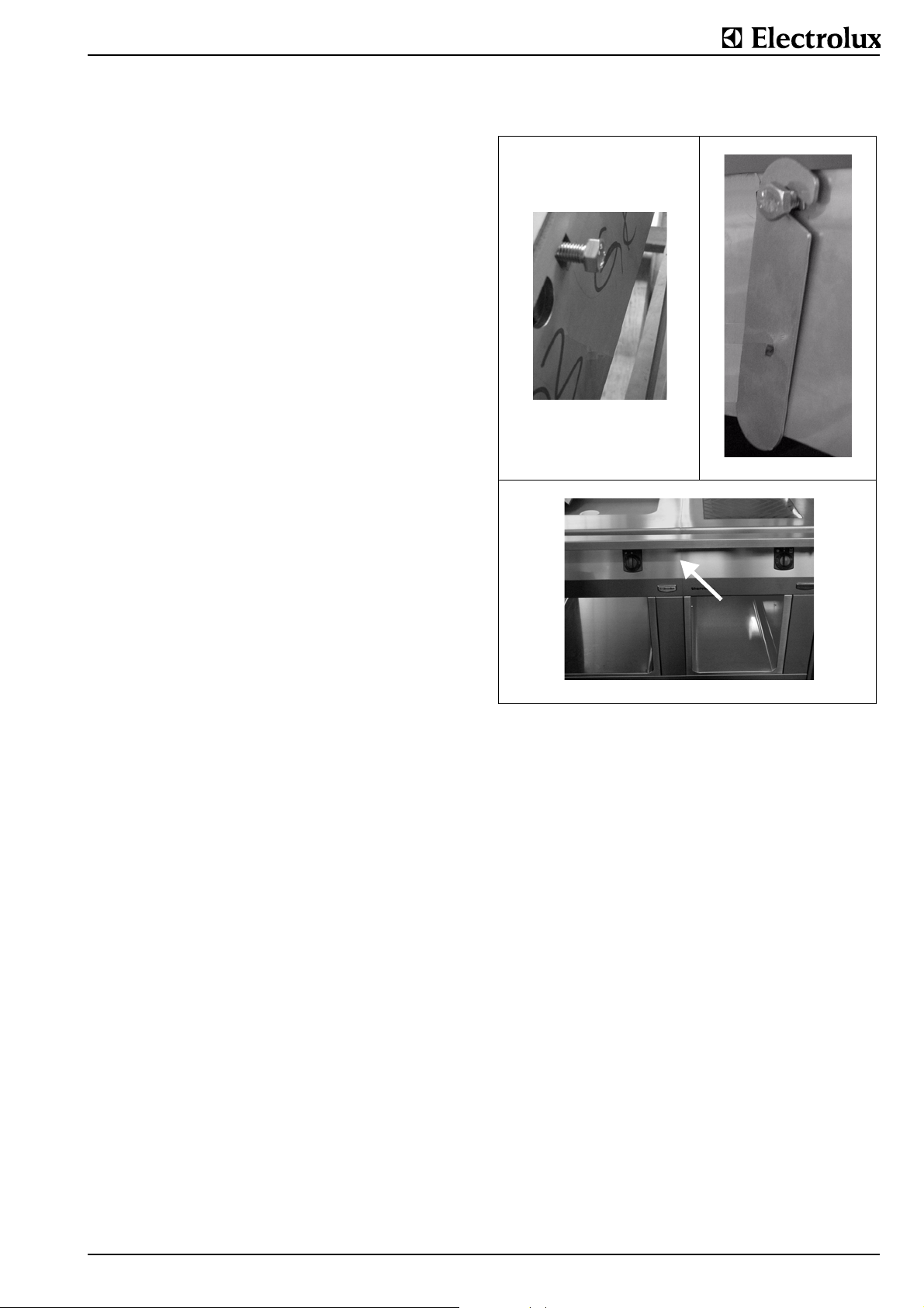
6. SPECIFICATION PLATE
The specification plate (E) is located in each case inside and
outside on the right of the operator panel (C) (Fig. 5).
The serial number is marked on the type plate. The 8 digits
give following information:
Y last digit of the year of production
WW week of production
XXXXX running number
Page 4 62.9534.01_UL
INSTALLATION INSTRUCTIONS
II . INSTALLATION INSTRUCTIONS
1. INSTALLATION
The appliance is designed for connection to fixed lines. The
appliances are suitable for setting up as single appliances or as
a group of appliances. They can be set up freely in the room,
side by side, at the side and/or at the back against a w al l.
Gaps between two appliances or appliance and sidewall
should be filled with a FDA approved silicone such as Sa mco
RTV103.
1.1 DISTANCES
If an appliance is set up next to or against temperature-sensitive furniture or similar, a safety gap of approximately 6“ (150
mm) should be maintained or some form of heat insulation fitted.
The walls must be made up of non-combustible material like
tiles or steel.
1.2 HEIGHT ADJUSTMENT
Appliance on feet: Alignment is carried out by screwing the
Appliance on
steel plinth:
Appliance on feet.
lower foot parts in or out.
Irregularities or differences in height can
be equalized by inserting one or several
strips of chrome nickel steel.
D Turn the lower part of the feed to adjust the appliance high.
The feet are adjustable from 4“ to 8“ (100 to 200 mm). A high
of 8“ (200 mm) can be recommended and results in an appliance high of 35,4“ (900 mm).
Note:
Adjustment of the legs shall provide an unobstructed
clearance of minimal 6“ (150 mm) and maximal 8“ (200
mm) beneath the unit due to sanitary and stability
aspects.
The lower part of the foot must not be unscrewed too far.
The exposure of threads is prohibited.
1.3 ASSEMBLING TWO APPLIANCES
(2)
(1)
(1)
(2)
a
b
1
c
Fig.1 Lateral connection
(3a)
(1)
(3b)
(2)
(3c)
(3c)
The assembly kit contains two of each of the following:
caged nuts (1 / Fig.1) pre-assembled on the right-hand side of
the appliance, hexagonal screws M8x25 (1 / Fig.1) and mounting links (2 / Fig.1)
D Remove the control panels from both appliances as in 2.2
D Remove the front panels from both appliances as in 2.1
D Keeping the screw (1 / Fig.1) loose, turn it until it is approxi-
mately 5 mm deep in the caged nut.
Positioning the appliances:
D Place the appliances next to one other.
D Align for position and height.
Connect the appliances:
D Fit the mounting link (2 / Fig.1) into the inside of the second
appliance's left connecting plate.
D Tighten the screws.
Note
If required, the caged nuts can also be fitted on the other side
of the appliance.
62.9534.01_UL Page 5
 Loading...