

Page 1
Page 2
Page 3
Page 4
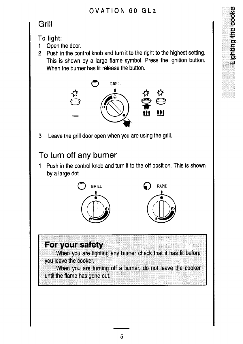
Page 5
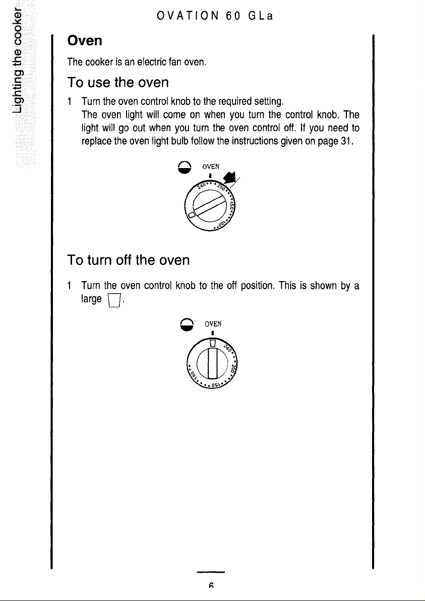
Page 6
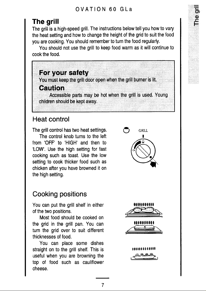
Page 7
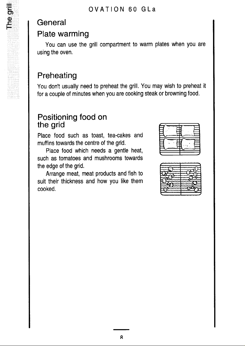
Page 8
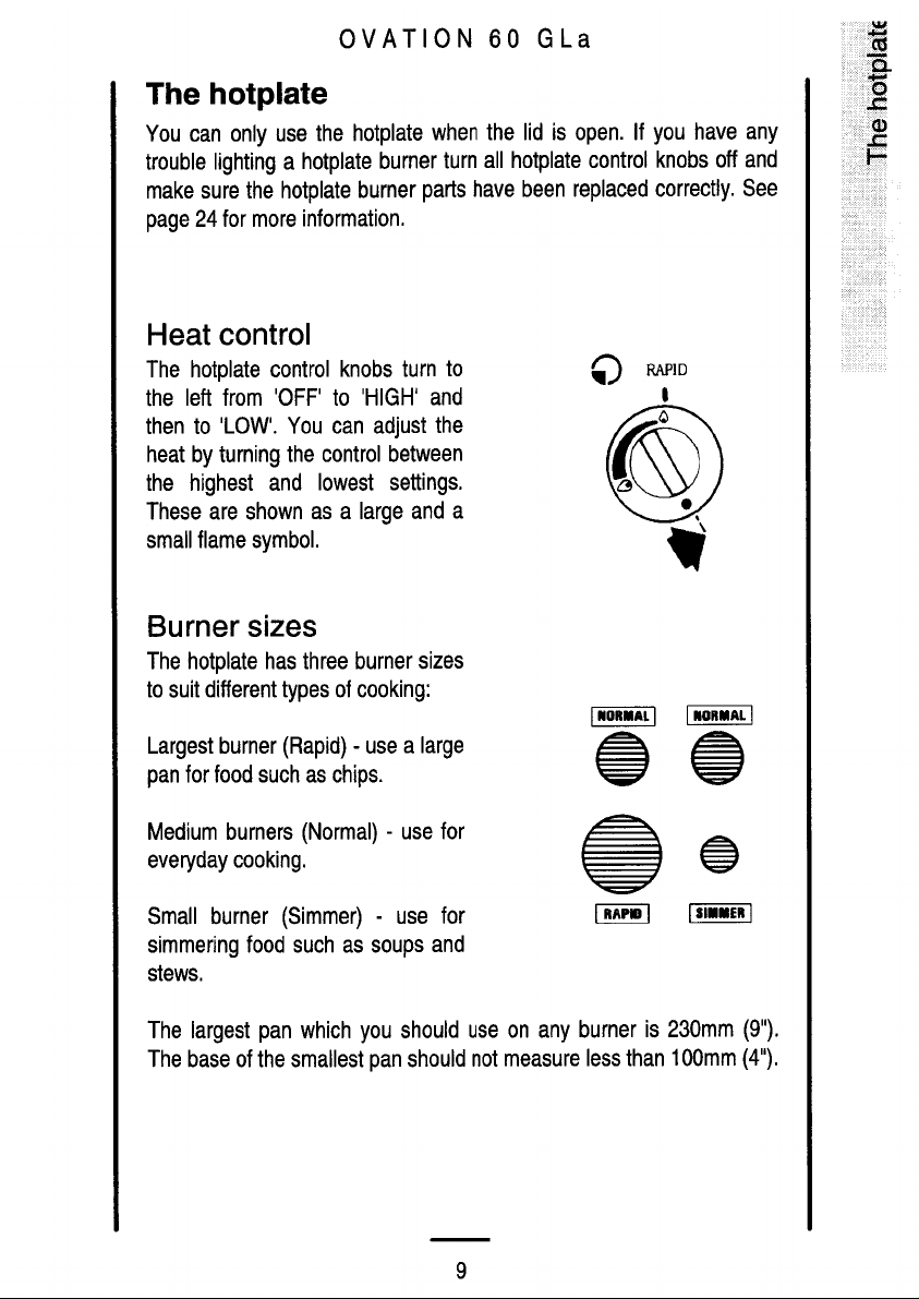
Page 9
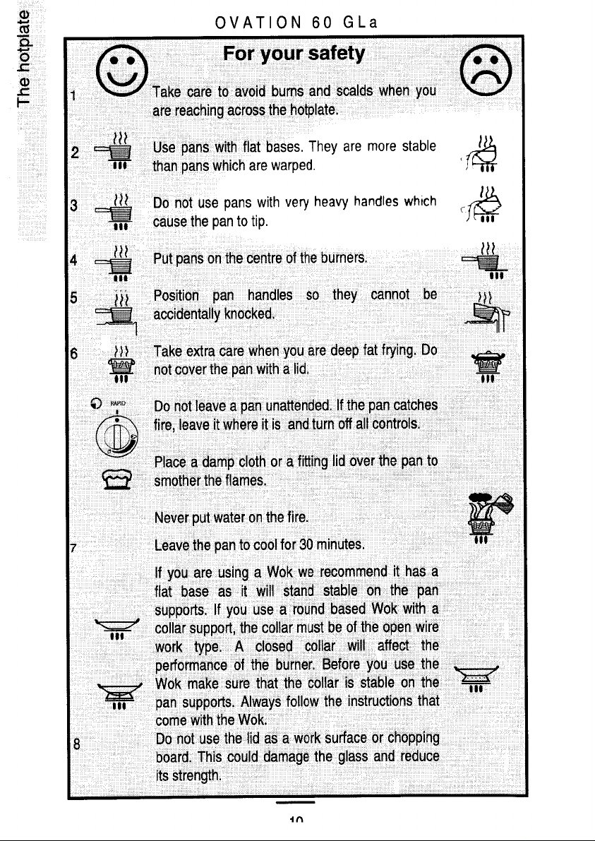
Page 10
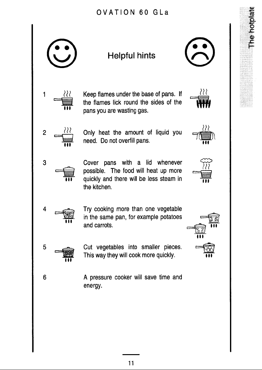
Page 11
Page 12
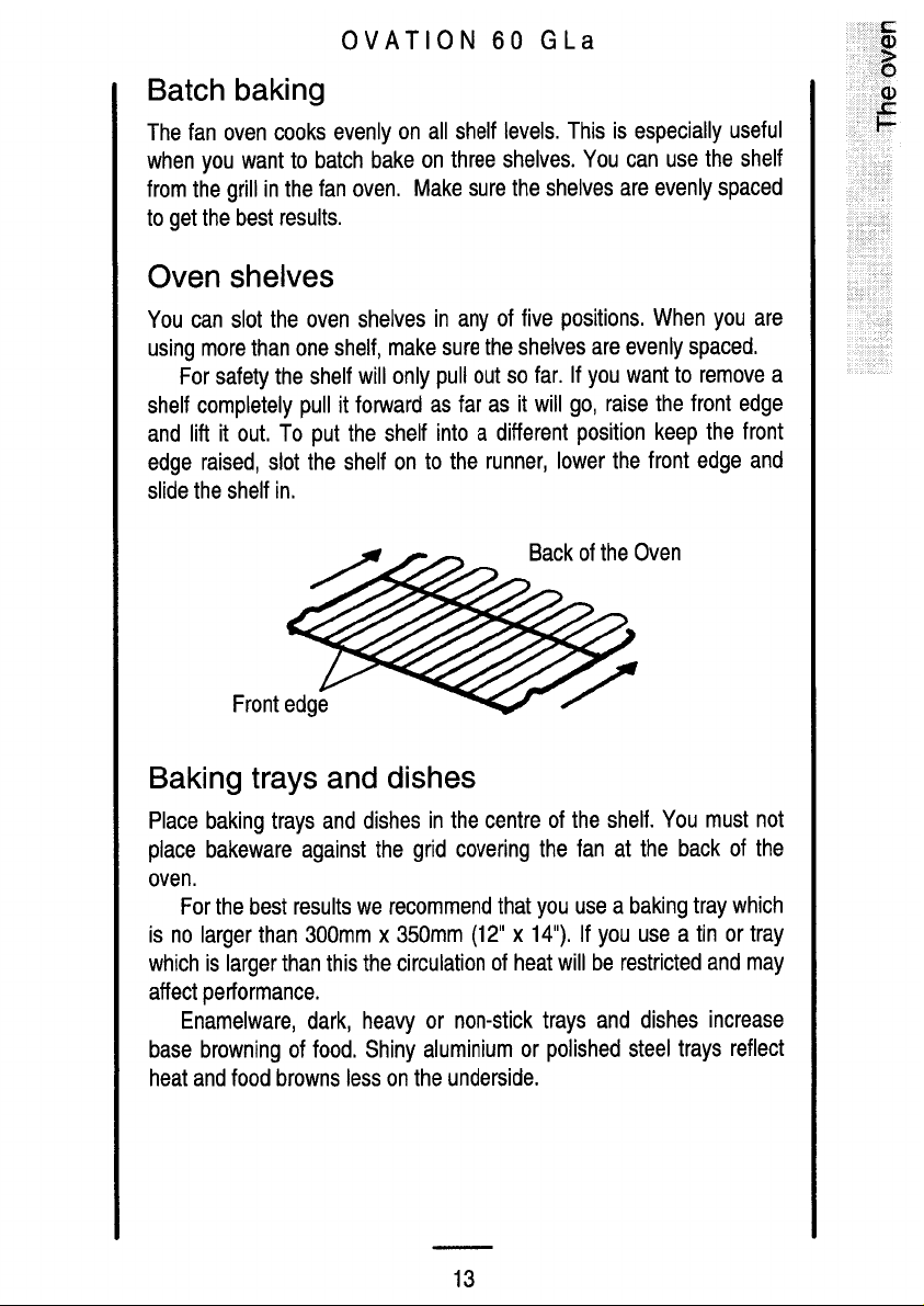
Page 13
Page 14
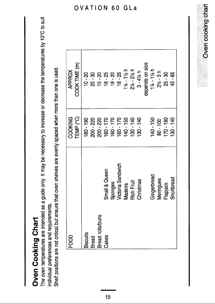
Page 15
Page 16

Page 17

Page 18

Page 19

Page 20

Page 21

Page 22

Page 23

Page 24

Page 25

Page 26

Page 27

Page 28

Page 29

Page 30

Page 31

Page 32

Page 33

Page 34

Page 35

Page 36

Page 37

Dual Fuel Cooker
G.C. Number: L.P.GAS WHITE
INSTALLATION INSTRUCTIONS
THIS APPLIANCE IS ONLY AVAILABLE FOR USE WITH L.P.GAS.
CHECK THAT THIS MODEL IS SUITABLE FOR THE TYPE OF SUPPLY
AVAILABLE.
IN THE INTEREST OF SAFETY THIS APPLIANCE MUST BE INSTALLED
AND/OR SERVICED BY A COMPETENT PERSON AS STATED IN THE GAS
SAFETY (INSTALLATION AND USE) REGULATIONS CURRENT EDITIONS.
Serial number and
Gas Council number
at front frame. Data badge on
top rear of panel.
LEAVE THESE INSTRUCTIONS WITH THE USER.
1
Page 38

CONTENTS
page
Technical Data 2
Safety Requirements 3
Provision for Ventilation 3
Location of Appliance 4
Installation 5
Testing 8
TECHNICAL DATA
DIMENSIONS
Height to hotplate 900mm (nominal) 600mm (nominal) 600mm
Space for fixing at hotplate level 2mm minimum clearance
Space for fixing above hotplate level Flush-see important note 'Location of Appliance' page 4.
Minimum space above hotplate 787mm (If a cooker hood is fitted refer to the cooker hood
Weight of appliance 64.5kg.
Minimum distance from rear wall 5mm (spacer given by pressed spacer on vent panel).
CONNECTIONS
Gas Rear left hand side of cooker at hotplate level.
Electric 230V 50 Hz mains 3 core cable is supplied with an integral,
Height Width Depth
(to front of
door panel)
installation instructions).
Rc½ (½" B.S.P. female).
moulded plug fitted with a 13 amp fuse.
IGNITION
Spark generator APCO 5MG 16913
GRILL
Heat Input 3.0kW (215 g/h)
Injector Marking 088
Injector Size 0.88mm
Cone Height Not applicable as flame burns on surface of gauze
HOTPLATE
Heat Input 1.0kW 2.0kW 2.0kW 2.7kW
(71.85 g/h) (143.7 g/h) ( 143.7 g/h) (194 g/h)
Injector Marking 051 072 072 083
Injector Size 0.51mm 0.72mm 0.72mm 0.83mm
Cone Length 10mm 15mm 15mm 15mm
2
L.P.Gas
L.P.Gas
R.H.F. R.H.R. L.H.R. L.H.F
Page 39

MAIN OVEN
Heat Input 2.5 kW
Electric
GENERAL
Ignition H. T. Spark
Spark Gap 3-4mm
IMPORTANT - SAFETY REQUIREMENTS
This appliance must be installed in accordance with the Gas Safety (Installation and Use) Regulations
Current Editions and the I.E.E. Wiring Regulations. Detailed recommendations are contained in the
following British Standard Codes of Practice - BS.6172, BS.5440: Part 2 and B.S.6891. All British
Standards must be 'Current Editions'.
PROVISION FOR VENTILATION
This appliance is not connected to a combustion products evacuation device. It shall be installed and
connected in accordance with current installation regulations. Particular attention shall be given to the
relevant requirements regarding ventilation.
The room containing the appliance should have an air supply in accordance with BS.5440: Part 2 Current
Edition. All rooms require an openable window or equivalent and some rooms will require a permanent
vent as well. For room volumes up to 5m³ an air vent of 100 cm² is required; for room volumes between
5m³ and 10m³ an air vent of 50cm² is required. If the room has a door that opens directly to the outside,
no air vent is required. For room volumes that exceed 11m³ no air vent is required. If there are other fuel
burning appliances in the same room, BS.5440: Part 2 Current Edition should be consulted to determine
the requisite air vent requirements.
If your cooker is in use over a long period of time you may need additional ventilation in your kitchen. This
can be achieved by opening a window or, if an external fan or cooker hood is fitted, switching this on or to a
higher setting.
3
Page 40

LOCATION OF APPLIANCE
787
This is a type X appliance which means it is freestanding and can be fitted with cabinets on one or both
sides. This appliance must not be installed in a bed-sitting room of volume less than 20m³ or in a bathroom
or shower room. It is essential that the appliance is positioned as stated below (see Fig. 1a)) i.e. shelves,
wall cabinets and cooker hoods must be fitted a minimum of 787mm directly above the top of hotplate and
400mm above the hotplate when fitted in line with the outside of the appliance. If the units are intended to
be fitted adjacent to the appliance but less than 400mm above the hotplate, then a minimum space of
100mm must be maintained between the sides of the unit and the appliance (see Fig.1b). Curtains must
not be fitted immediately behind the appliance or within150mm of the sides of the hotplate. If fitted next to
or between two base units a minimum space of 1mm must be left between each unit and the sides of the
appliance. The levelling feet fitted to the appliance will achieve a nominal height to hotplate trims of 900mm
- 2mm +20mm. If the appliance needs to be higher that 920mm, then an optional height adjustment kit is
available which will raise the appliance to a nominal height of 945mm (wheels kit no. 359079800 G.C. No
074 498).
400
787
100
Fig.1a All dimensions in mm Fig.1b
less
than
400
4
Page 41

INSTALLATION
1. PARTS REQUIRED
The loose hotplate parts are packed in the polystyrene fitment on top of the hotplate.
2. LEVELLING THE APPLIANCE
If the appliance requires levelling or its height adjusting (from the hotplate to any working surface), the
procedure below must be followed:
1. Loosen the lock nuts securing the rear wheels, using a 13mm spanner. Access to these lock nuts can
be gained through a slot in the rear of the plinth, as shown in Fig.1c.
2. Adjustment to suit floor conditions or height is obtained by rotating clockwise or anticlockwise the
hexagonal feet/wheels, at the front and rear of the appliance.
NOTE: The rear wheels must only be rotated through half or whole turns.
3. A spirit level should be placed on a baking sheet on one of the oven shelves to confirm the appliance
is correctly levelled.
4. Once the appliance is at the correct height and levelled, the rear wheel should be locked into position
by means of the lock nuts, having first made sure the wheels are once again parallel to the side of the
appliance.
Fig.1c
Rear of
Appliance
Plinth
Lock Nut
Rear Wheel
5
Page 42

3. FITTING THE STABILITY BRACKET
It is recommended that if the appliance is to be installed with a flexible supply pipe a stability bracket
(SK.4729.A) is fitted and is available from your supplier (see Important Safety Requirements, Page 3).
These instructions should be read in conjunction with the leaflet packed with the stability bracket.
1. Place the appliance in its intended position and level appliance.
2. Mark off 300mm from the left hand side of the appliance as shown in dimension 'A', Fig 2a. This is the
centre line of the fixing bracket.
3. Draw a line 100mm from the front edge of the levelling feet (see Fig.2a) and remove appliance from
its position. Mark off dimension 'B' (see Fig.2a) back from this line on the centre line of the bracket to
locate the front edge of the lower bracket. Fix lower bracket (with two fixing holes) to the floor then
measure the height from floor level to engagement edge on back of appliance, dimension 'C' of
Fig.2b.
4. Assemble upper bracket to lower bracket so that underside of bracket is dimension 'C' +3mm above
floor level.
Reposition appliance and check that top bracket engages into appliance back as shown in Fig. 2b.
6
487mm (B)
100mm
(A)
300mm
Fig.2a Fig.2b
(C)
Page 43

4. CONNECTING TO GAS
0
This appliance is designed to be installed with an
100
50
Fig.3
appliance flexible connection only. (The flexible supply
pipe must be suitable for use at 70° above ambient).
Supply piping should not be less that R³/
8
. Connection
is made to the Rc ½ (½" B.S.P.) female threaded entry
pipe located just below the hotplate level on the rear left
hand side of the appliance. NOTE: ONLY LIQUID
SEALANTS TO BE USED WHEN INLET GAS PIPE IS
FITTED TO SHUT OFF VALVE I.E.: DO NOT USE
P.T.F.E. SEALANT TAPE. Check for gas soundness
after connecting to the gas supply.
850
The gas bayonet connector must be fitted in the shaded
area indicated in Fig.3. Take into account that it must
be possible to pull the appliance forward sufficiently.
The hose must not get caught on the stability bracket.
IMPORTANT: FLEXIBLE TUBING USED MUST
COMPLY WITH BS. 669 CURRENT EDITION.
L.P.G. FLEXIBLE CONNECTIONS MUST BE OF A
250
TYPE SUITABLE FOR L.P.G. AND CAPABLE OF
OPERATION UP TO 50 mbar AND TO CARRY A RED
STRIPE, BAND OR LABEL.
All dimensions in mm
400
5. CONNECTION TO THE ELECTRICITY SUPPLY
WARNING: THIS APPLIANCE MUST BE EARTHED.
DO NOT EARTH THIS APPLIANCE TO THE GAS
SUPPLY PIPING.
This appliance must be connected to a 230V A.C. 50Hz
supply. It is supplied with 2 metres of 15 amp 3 core
cable incorporating a moulded 13 amp plug , fitted with
a 13 amp fuse, which can be plugged directly into the
nearest suitable socket. If this is not long enough, the
supply cable can be either:(i) Replaced totally by a longer cable at least 1.5mm²
nominal cross sectional area (30/0.25mm).
(ii) Extended by using a B.E.A.B. approved 3-way
sealed flex connector with integral flex clamps.
IF THE MOULDED PLUG IS CUT FROM THE
CABLE FOR ANY REASON, IT MUST BE
DESTROYED OR DISPOSED OF SAFELY, AS
THE PROTRUDING WIRES WILL BE AN
ELECTRIC SHOCK HAZARD.
If any other type of plug is used it should incorporate a 13 amp fuse in either the plug or adapter or at the
distribution board.
If the cable has to be threaded through small apertures in cabinets etc., it may be disconnected from the
appliance, then re-connected to as shown in Fig.4.
Fig.4
70
450
DO NOT EXTEND THE CABLE USING PLASTIC OR CERAMIC CONNECTION TERMINAL BLOCKS
AND/OR INSULATION TAPE.
ALL EXTERNAL WIRING BETWEEN THE APPLIANCE AND THE ELECTRICAL SUPPLY SHALL
COMPLY WITH I.E.E. WIRING REGULATIONS.
7
Page 44

If the wiring is extended or a completely new cable fitted a 3-pin 13 amp plug should be fitted. (See Fig.4a).
Connect the wires as follows:
BROWN to the Live Terminal.
BLUE to the Neutral Terminal.
GREEN and YELLOW to the Earth Terminal.
As the colours of the wires in the mains lead which you
fit may not correspond with the coloured markings
identifying the terminals in your plug, proceed as follows:
The wire which is GREEN and YELLOW must be
connected to the terminal in the plug which is marked
with the letter 'E' or by the earth symbol or coloured
GREEN or GREEN and YELLOW.
The wire which is coloured BLUE must be connected to
the terminal which is marked with the letter 'N' or
coloured BLACK.
The wire which is coloured BROWN must be connected
to the terminal which is marked with the letter 'L' or
coloured RED.
FIT A 13 AMP FUSE TO THE PLUG HOLDER.
Ensure that the supply cable cannot get caught by the stability bracket. Plug in the appliance.
GREEN AND
YELLOW
BLUE
13 AMP
BROWN
Fig.4a
6. PRESSURE TESTING
1 The hotplate rapid burner injector is used as a pressure test point.
2 Lift the lid and connect the pressure gauge to the rapid burner injector.
3 Check the supply pressure by turning rapid burner tap on full and one other hotplate tap full on and
light the appropriate burner. The pressure must be set to 28mbar for use on butane or 37mbar for use
on propane.
4. Turn off the taps and disconnect the pressure gauge.
7. CHECKING THE GRILL
Place the grill pan containing the trivet into the grill compartment. To light the grill burner , turn the grill tap
to its full on position, then press the ignition button until the burner is lit.
8. CHECKING THE HOTPLATE
Lift the lid. Fit the burner crowns and caps ensuring that they are correctly seated. Fit the pan supports.
Check each of the hotplate burners in turn by turning the hotplate tap to it's full on position then pressing
the ignition button until the burners are lit.
9. CHECKING LID SHUT-OFF DEVICE
1. Lift the lid.
2. Turn one hotplate burner tap to its full on position, then push and release the ignition button.
3. Close lid. There should now be no gas supply to the hotplate and the burner will go out.
4. Turn off the hotplate tap and lift the lid. The gas supply should now be restored to the hotplate, when
the tap is turned on.
8
Page 45

10. CHECKING THE MAIN OVEN
CONTROLS
TO SET THE TIME OF DAY (see Fig.5)
1. Turn on the electricity supply and ensure that
the thermostat is in the off position.
1a. Before setting timer read important note below.
2. Rotate the left hand clock knob to manual and
back to the clock position.
3. Set the time of day by rotating the right hand
knob. Note that it is a 24 hour clock.
4. Rotate the left hand clock knob back to the
manual position.
NOTE: When setting the time of day with the selector
knob in the clock position only, this will activate the timer for seven seconds after selection. This means
that when setting the time of day in this function the time can only be set by using the right hand knob
within a seven second period.
After seven seconds have elapsed from when the correct time of day has been set, the timer ceases
to be active and subsequent operation of the right hand knob will not change the time setting.
When the right hand knob is turned anti-clockwise after the seven second delay period, a choice of
three audible signals are available. To select the choice of signal required rotate knob anti-clockwise and
release. Repeat procedure to choose desired signal.
Fig.5
11. CHECKING THE MAIN OVEN
1. Set the clock as described above, the oven is now ready for manual operation.
2. Turn the main oven thermostat to maximum . The oven fan and lamp will operate and after a short
period the heat from the oven element may be felt when the oven door is opened.
3. Turn off the thermostat and check that the oven fan stops and the oven lamp goes out.
12. AUTOMATIC OPERATION
Having set the clock up as described above, turn the left hand knob to the 'cook' position and set the right
hand knob to show a cooking time of two minutes (0.02).
Turn the left hand knob to the 'stop' position; the time shown on the display is now the time of day with two
minutes added on. Rotate the right hand knob to add two minutes to this time to give a two minute delay.
Turn the left hand knob to the 'auto' position to complete the programming sequence, the clock now shows
the time of day again with 'auto' glowing continuously.
Turn the oven thermostat on and two minutes after setting, the oven fan and lamp should operate.
Two minutes after the oven starting , the timer should cut off power to the oven and the audible signal
should sound. The signal is continuous and it may be switched off at any time by rotating the left hand
knob.
Return timer to manual by rotating the left hand knob to the 'manual' position.
13. CHECKING THE MAIN OVEN LIGHT
Turn the main oven thermostat knob full on and check that the main oven light is working. Turn off the
thermostat.
GENERAL NOTE
Instruct the user on how to use the appliance and its ignition system. Refer the user to the wording in the
inside cover of the Users Instructions which gives advice on the safe operation of the appliance.
9
Page 46

101112
Page 47

Page 48

Bordesley Green Road, Birmingham B9 4UB
Drg. No. 311317600
Parkinson Cowan
 Loading...