

Page 1
WARNING: Your Super Switcher comes equipped with an Electro-Harmonix 9.6DC-
200BI power supply. The Super Switcher requires 150mA at 9VDC with a center
negative plug. Use of the wrong adapter or a plug with the wrong polarity may damage
your Super Switcher and void the warranty. Do not exceed 10.5VDC on the power plug.
Power supplies rated for less than 150mA will cause the Super Switcher to act unreliably.
SUPER SWITCHER
Programmable Effects Hub
Congratulations on your purchase of the Super Switcher, a full-featured
programmable effects hub that is capable of controlling your entire rig. The
Super Switcher is able to handle jobs as simple as an effects loop switcher or as
complex as a programmable effects loop preset designer. The Super Switcher
can send tap tempo to other pedals, includes two general purpose control
outputs, and features MIDI input and output allowing automated control over
just about any MIDI device for nearly endless possibilities. Scratch the surface of
tone shaping with the Super Switcher and achieve studio style effects
programming that cannot be accomplished with traditional pedal set ups. No
more tap dancing!
FEATURES
Programmable pedal switcher
Mechanical relay switching for true bypass signal paths
8 FX loops (6 mono & 2 stereo)
16 Banks of 8 presets each
Pedalboard controller with MIDI In and Out
1 hardwired insert loop between FX loops 5 and 6
2 Instant Access Modes allowing direct control over FX loops
Stereo output boost
Onboard Tap Tempo with TAP output
Tuner output
2 general-purpose control footswitches
1
Page 2

TABLE OF CONTENTS
Notes and Specifications 2
Controls and Connections 3
Ins, Outs, Sends and Returns 3
Illuminated Buttons 4
Footswitches and LEDs 4
Boost and Value Knobs 5
Preset Mode 6
Instant Access Mode 7
Control Functions 8
MIDI Control 9
MIDI Receive Message Tables 11
Setup Menu 12
Restoring Factory Settings 15
Warranty Information and Compliance 16
NOTES AND SPECIFICATIONS
Audio input impedance: 2Mbufferorboostonly
Audio output impedance for each output: 470bufferonly
Audio output impedance for each output: 1Kbooston
Current draw: 150mA
Maximum input signal level: +11 dBu
Bypass: Mechanical relay true bypass switching
2
Page 3

CONTROLS AND CONNECTIONS
- INS, OUTS, SENDS AND RETURNS -
The Super Switcher has eight switchable effects loops, an insert loop,
mono input and stereo outputs.
Mono Input: Connect your guitar or instrument to the IN jack.
Stereo Outputs: Connect your amp(s), other effects pedals or mixer to
the OUT L and OUT R jacks. We recommend only using the L channels if
working in mono throughout your signal chain.
Mono Effects Loops 1-6: Active when illuminated buttons L1-6 are lit.
Effects loops 1-6 are mono loops arranged in series. Loops 1-6
correspond respectively to the illuminated buttons L1-6. When the
illuminated button is lit, the corresponding effects loop is active
and the signal is routed out the SEND jack and in through the RTN
(return) jack.
NOTE: If the loop is active with nothing plugged into it, the signal
will be cut off and no sound will come out of the output.
Insert Loop: Always on, hardwired loop between effects loops 5 and 6.
Series insert loop is placed between effects loops 5 and 6
When nothing is plugged into the SEND and RETURN of the insert
loop the signal bypasses the insert loop.
If an effect is placed in the insert loop, the signal will always be
routed through the effect.
Perfect for always having manual control of a certain effect.
Ideal for an always ON type of effect such as a volume pedal.
The Insert Loop is active even when master bypass is engaged.
Stereo Effects Loops 7-8: Active when buttons L7-8 are lit.
Effects loops 7 & 8 are stereo loops arranged in series. When
either of their illuminated buttons are lit (L7-8), the corresponding
effects loop is active.
Loop 7 has a single, mono SEND jack.
Loop 7 has separate left and right RTN jacks.
Loop 8 has separate left and right SEND jacks.
Loop 8 has separate left and right RTN jacks.
Loop 7 or 8 can be used in mono: connect to only their L channels.
3
Page 4

Bypass Switching: Analog, mechanical relay bypass switching.
With no additional features enabled (buffer, boost, etc.) the Super
Switcher features mechanical relay true bypass switching.
Master Bypass: The Super Switcher’s CTRL 1 footswitch can be set up
to engage master bypass. Master bypass connects the input signal to
both OUT L and OUT R. The hardwired Insert Loop between Loops 5 & 6
is still active, even in master bypass.
- ILLUMINATED BUTTONS -
There are 10 illuminated buttons on the Super Switcher: L1-8, PC & CC.
L1-8 (Loop1 – Loop8):
The illuminated buttons for loop 1-8 both control and display the
on/off status of the corresponding effects loop.
Pressing an illuminated button will light the button and enable the
corresponding effects loop.
PC and CC Buttons: MIDI Program Change and Control Change.
The illuminated buttons for PC and CC control the message
transmit status for the Super Switcher.
When the PC illuminated button is pressed the Super Switcher will
transmit the associated Program Change information.
When the CC illuminated button is pressed the Super Switcher will
transmit the associated Control Change information.
The PC and CC buttons are also used to edit MIDI messages.
- FOOTSWITCHES AND LEDS -
Footswitches 1-8:
Footswitches 1-8 engage and disengage the corresponding presets
1-8 for the bank that is currently selected.
In both Instant Access Modes:
control the corresponding on/off status of effects loops 1-8.
Footswitches BANK UP and BANK DOWN:
BANK UP and BANK DOWN footswitches increment or decrement
through the preset banks. There are 16 banks each with 8 presets.
IA
or
IA2
, footswitches 1-8 directly
PRESET Footswitch:
The PRESET footswitch toggles the Super Switcher between its
normal Preset Mode and a manual mode called Instant Access
Mode.
4
Page 5

TAP Footswitch:
Two or more presses on the TAP footswitch updates the BPM
setting for the Super Switcher.
The TAP footswitch also controls the tempo signal that is output
from the TAP jack.
TUNER Footswitch:
When the TUNER footswitch is pressed, the Super Switcher sends
the IN signal directly to the TUNER jack.
When TUNER is active, the Super Switcher’s effects loops and
outputs are muted.
BOOST Footswitch:
The BOOST footswitch turns ON/OFF the stereo output boost.
The BOOST circuit is after loop 8.
CTRL 1 Footswitch:
The CTRL 1 footswitch can be used to switch amp channels,
trigger remote effects etc.
CTRL 1 can be set normally open or closed.
CTRL 1 can be set to momentary or latching.
CTRL 1 can be set as a master bypass button.
CTRL 2 Footswitch:
The CTRL 2 footswitch can be used to switch amp channels,
trigger remote effects, etc.
CTRL 2 can be set to normally open or closed.
CTRL 2 can be set to momentary or latching.
- BOOST AND VALUE KNOBS -
BOOST Knob:
The BOOST knob is a manual analog control for the switchable
stereo output clean boost.
At fully counter-clockwise, boost is at unity gain. Turn up the
BOOST knob for a volume boost.
The maximum gain of the Boost circuit is +20dB.
VALUE Rotary Encoder Knob:
The VALUE knob is a rotary encoder with a push button. This knob
continuously turns in either direction. VALUE is used to navigate
and edit the Super Switcher’s menus.
VALUE can be used to edit the BPM of the Super Switcher, change
banks, navigate menus and change settings.
5
Page 6

PRESET MODE
ENGAGE PRESETS
Preset Mode is the main default mode for the Super Switcher.
When in Preset Mode, the PRESET footswitch LED will be lit, and the
character display will show the current BANK number.
In Preset Mode each footswitch: 1-8, engages or disengages the saved
preset: 1-8 for the current bank.
SELECTING BANKS
To change the current bank press the BANK UP or BANK DOWN
footswitch. VALUE can also be turned to change banks.
When a bank change is made, the bank number in the character display
will begin to blink. The new bank is not active until you press the VALUE
encoder button. The newly selected bank will load with no preset
selected.
Alternatively, both a new bank and a preset can be loaded by pressing
footswitches 1-8 while the bank numbers are blinking. The new preset
will load and the display will stop blinking.
The display will also stop blinking if you return to the current bank
without activating a new preset.
EDITING/SAVING PRESETS
The Super Switcher automatically saves any edits that are made to the
current preset.
Presets are saved at the time you press footswitch 1-8. Whether you
disengage the current preset or directly engage a different preset, any
edits will be saved to the preset that was being worked on.
When a preset is engaged, press the illuminated buttons to enable or
disable effects loops and MIDI messages. The control functions such as
BOOST, CTRL 1 and CTRL 2 can also be saved per preset.
6
Page 7

INSTANT ACCESS MODE
INSTANT ACCESS MODE 1
Instant Access Mode 1 is used to have instant access to all of the effects
loops using the current preset as a basic set up.
ENTERING INSTANT ACCESS MODE 1: When a preset is active,
pressing the PRESET footswitch will turn off the PRESET LED and the
Super Switcher will enter Instant Access Mode. The Character display
will read IA. The LEDs for footswitches 1-8 will change to mirror the
illuminated buttons. If preset 01.1 had loops 4 and 6 engaged, in
Instant Access Mode, the LEDs for footswitches 4 and 6 will light.
The LED for footswitch 1 will turn off since that effect loop is not
active.
MAKING CHANGES: Instant Access Mode can be used to quickly
turn effects on and off within a current preset. Simply press the
footswitch or press the illuminated button to engage or disengage
the corresponding effects loop.
SAVING CHANGES: To save the changes made in Instant Access
Mode to the current preset, press and hold the PRESET footswitch
until the IA character display blinks for a second. Any changes made
will be lost if Instant Access Mode is exited without saving.
EXITING INSTANT ACCESS MODE 1: To return to Preset Mode
press the PRESET footswitch. Depending on whether the edits made
in Instant Access Mode were saved, either the old preset will reload,
or the new preset with the new changes will load.
INSTANT ACCESS MODE 2
Press the PRESET footswitch while no preset is active and the Super
Switcher will enter the 2nd Instant Access Mode.
character display and the IA2 preset will be loaded. IA2 will auto save
any changes made to the IA2 preset. There is only one IA2 preset and it
can be called from any bank as long as no preset is active. To exit simply
press the PRESET footswitch.
IA2
will show on the
7
Page 8

CONTROL FUNCTIONS
BOOST
The Super Switcher has a clean boost function that is placed after loop 8
at the output of the signal chain. The boost is stereo—using the boost
function will not collapse a stereo signal to mono. The boost function can
be turned on and off at any time by pressing the BOOST footswitch. The
ON/OFF status of the boost function can be saved per preset but the
amount of boost gain can only be adjusted by turning the BOOST knob.
The BOOST knob setting is not saved with presets.
CTRL 1 & CTRL 2
The Super Switcher has two control functions that can be used as
general-purpose switches. This is useful to change channels on
amplifiers, turn amp reverb or tremolo on and off, or switch parameters
on effects pedals remotely. The control functions can be configured as
normally open or normally closed switches. Latching or momentary
behavior can also be selected. The CTRL 1 function can also be set up to
act as a master bypass for the Super Switcher’s effect loops.
Engage/disengage the control functions by pressing the CTRL 1 or CTRL
2 footswitches. The control functions are always live and available. The
control function ON/OFF status can be saved per preset. Each switches
setup behavior is global for CTRL 1 and CTRL 2 and not saved with
presets. See SETUP MENU.
TAP FOOTSWITCH & OUTPUT
The Super Switcher has an auxiliary output jack for tap tempo. This
output can be configured to send out different signals based on the
setup. See SETUP MENU.
When the
outputs updated tap signals based on adjusting the BPM with the VALUE
knob or new tempo information from the TAP footswitch. The Super
Switcher waits until a new BPM is set and then sends four tap pulses
from the TAP output jack. If the Super Switcher is receiving MIDI clock,
the TAP output will continuously send a tap signal at the same tempo as
the MIDI clock.
When
to the TAP footswitch, behaving like a manual tap tempo footswitch.
tAP
setting is set to ON, the Super Switcher automatically
tAP
setting is set to
OFF
, the TAP output directly mirrors presses
8
Page 9

MIDI CONTROL
PROGRAM CHANGE MESSAGES
The Super Switcher can send MIDI program change (PC) messages with
preset changes. For each preset, the Super Switcher can send one
program change message on any one channel or on all MIDI channels
(OMNI).
ENABLE PC MESSAGE:
• With the required preset active, press and release the PC
illuminated button to engage or disengage the PC message for the
selected preset. When the button is lit, the PC message is enabled
for the given preset so that each time the preset is recalled, the
PC message is output from the MIDI OUT port.
EDIT PC MESSAGE & CHANNEL:
• With the required preset active, press and hold the PC illuminated
button. The PC button will begin to blink and the character display
will show
•
PCN
show
• With the character display showing
character display will show a three-digit number.
• Turn VALUE to select the PC message number. The range is 000-
127.
• Press VALUE again to go back to
• Turn VALUE so the display shows
• Turn VALUE to select the PC send channel. The range is 01-16 and
ONI
• Press and hold VALUE to exit PC message edit.
CONTROL CHANGE MESSAGES
The Super Switcher can send MIDI Control Change (CC) messages—aka
continuous controller messages—with preset changes. For each preset,
the Super Switcher can send one full CC message. The Super Switcher
can send the message on any one channel or OMNI.
PCN
.
represents the PC message to be sent. Turning VALUE will
ChL
, which represents the PC message’s MIDI channel.
PCN
, press VALUE. The
PCN
.
ChL
. Press and release VALUE.
for Omni, which sends the PC message on all channels.
9
Page 10

ENABLE CC MESSAGE:
• Press the CC illuminated button to engage or disengage the CC
message for the selected preset. When the illuminated button is
lit, the CC message is enabled and will be sent whenever the
selected preset is recalled.
EDIT CC MESSAGE & CHANNEL:
• With the required preset active, press and hold the CC illuminated
button. The CC button will begin to blink and the character display
will show
•
CCN
to edit the CC value, and
• With the character display showing
character display will show a three-digit number.
• Turn VALUE to select the CC number. The range is 000-127.
• Press and release VALUE again to go back.
• Turn VALUE so that the display shows
VALUE to edit the CC message’s value. The range is 000-127.
• Press and release VALUE again to go back.
• Turn VALUE so that the display shows
VALUE to edit the CC message’s MIDI channel. The range is 01-16
plus
• Press and hold VALUE to exit CC message edit.
MIDI RECEIVE
The Super Switcher can be controlled by other MIDI devices. See
SETUP MENU. Global values for MIDI receive channel, MIDI thru and
MIDI clock ON/OFF are available in SETUP.
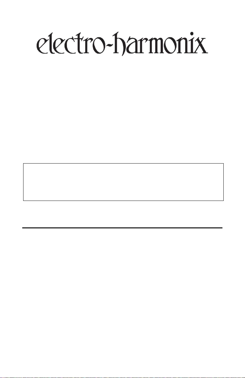
The tables on the following page list the Program Change (PC) and
Control Change (CC) messages that the Super Switcher responds to on
its MIDI IN connector.
PC Messages: Use PC messages to directly load presets through MIDI.
For example, if you want directly load preset 03.1, send PC 16.
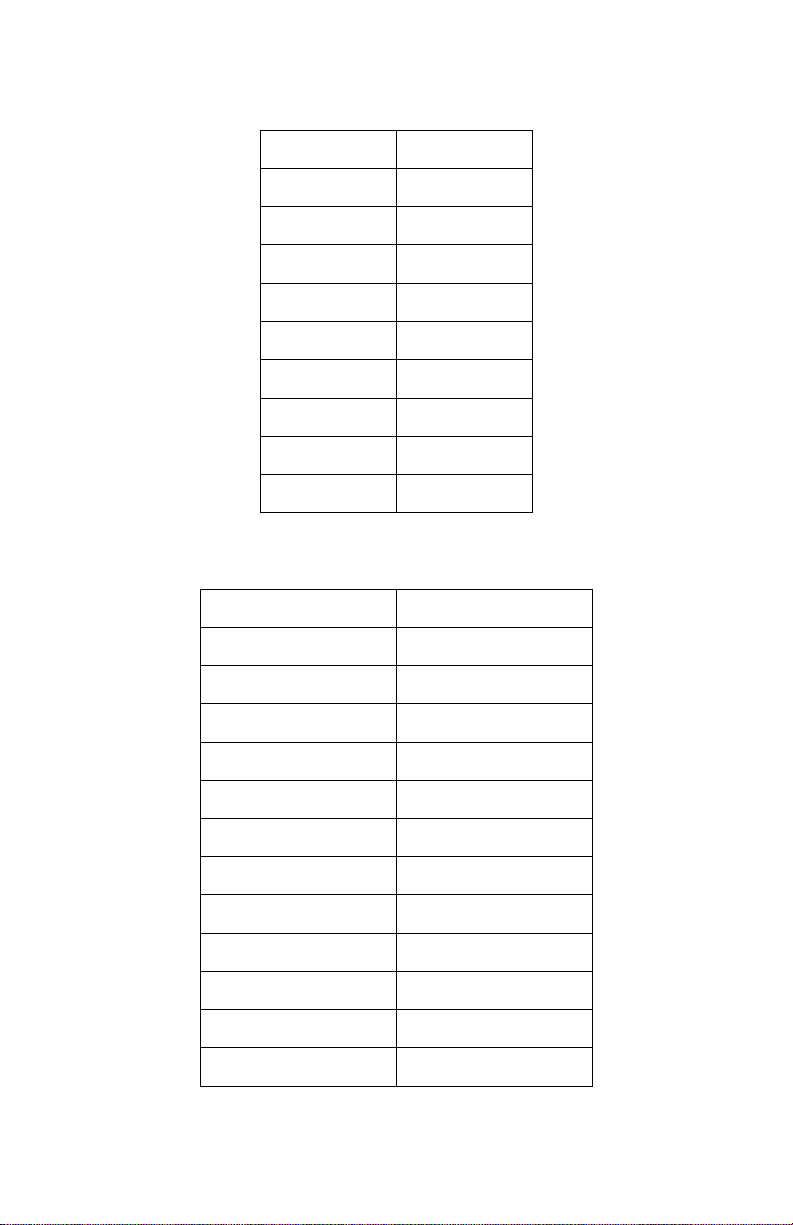
CC Messages: Use CC messages to directly perform button pushes
through MIDI. CC Values 0-63 send an “off” message, 64-127 send “on”.
We recommend interleaving on and off messages for the same button
push.
CCN
.
is used to edit the CC number. Turning VALUE will show
ChL
to edit the CC send channel.
CCN
, press VALUE. The
CCU
. Press and release
ChL
. Press and release
ONI
for Omni, which sends the CC message on all channels.
CCU
10
Page 11
PC Number
Preset
0
01.1
1
01.2
2
01.3
… … 8
02.1
9
02.2
…
…
126
16.7
127
16.8
CC Number
Function
102
Loop 1
103
Loop 2
104
Loop 3
105
Loop 4
106
Loop 5
107
Loop 6
109
Loop 7
108
Loop 8
110
Boost
111
Tuner
112
Control 1
113
Control 2
PC RECEIVE MESSAGES:
CC RECEIVE MESSAGES:
11
Page 12

SETUP MENU
GLOBAL SETTINGS
The Super Switcher has many global settings that help to maximize
flexibility. Access the Global Settings menu by doing the following:
ACCESS AND NAVIGATE GLOBAL SETTINGS MENU:
Make sure you are in Preset mode. The display should not show
IA
or
IA2
. If it does, press the PRESET footswitch.
Ensure a preset is not loaded. For example, the display might
show
01.2
. Unload the preset by pressing footswitch 2. Now the
display shows
Press and hold the VALUE knob for a couple seconds. The
character display will change to
The Global Settings menu is now active.
Turn the VALUE knob to scroll through all Global Settings
headings, such as
Press and release VALUE to jump in and out of each setting.
Turn VALUE to change the settings’ value. Press and release
VALUE to jump back up to the headings.
01._
.
bFR, bPn, tAP
bFr
.
, etc.
BUFFER SETTING (
• The
• Press and release VALUE to set the status of the buffer. Turn
• Press VALUE knob to go back. Turn VALUE to show
BPM SETTING (
• The
• Press and release VALUE to set the status of the BPM setting.
•
• Press and release VALUE to go back. Turn VALUE to show
bFr
setting controls the status of the input buffer. This is a
global setting and not per preset. The input buffer can help if long
runs of cables are causing high-end loss, particularly between the
Super Switcher and its effects loops or to an amplifier.
VALUE to select ON or
bPN
setting controls whether newly received BPM information
is applied globally to all presets or only to the selected preset.
Then turn VALUE to select
LOC
setting only updates the selected preset.
BPM of the entire Super Switcher.
bPN
bFr
):
):
OFF
.
LOC
12
or
GLO
bPN
.
.
GLO
will update the
tAP
.
Page 13

TAP SETTING (
• When
• Press and release VALUE to set the status of the TAP output. Turn
•
• Press and release VALUE to go back. Turn VALUE to show
CONTROL 1 SETTING (
• The
• Press and release VALUE, the character display will show
• Turn VALUE to select between
• Press and release VALUE to go back. Turn VALUE to show
CONTROL 2 SETTING (
• The
• Press and release VALUE and the character display will show
• Turn VALUE to select between
• Press and release VALUE to go back. Turn VALUE to show
MIDI RECEIVE CHANNEL SETTING (
• The
• Press and release VALUE and the character display will show
• Press and release VALUE to go back. Turn VALUE to show
tAP
tempo signals via the TAP output jack based on preset BPM or
received MIDI clock. When
sends signals that mirror presses of the TAP footswitch.
VALUE to select
ON
sets the TAP output to automatic; four tap signals will be sent
out every time the BPM is updated.
work like a manual tap tempo footswitch.
Ct1
setting controls the function of the CTRL 1 footswitch.
VALUE to select NO or NC. This is the switch behavior “normally
open” or “normally closed”. Normally open is most common. Press
and release VALUE again to show
momentary and
Ct2
Turn the encoder knob to select
behavior “normally open” or “normally closed”. Normally open is
most common. Press and release VALUE again to show
momentary.
ChL
receives MIDI messages.
Turn VALUE to select the MIDI receive channel between 1-16 or
ONI
for omni.
tAP
):
is set to ON, the Super Switcher automatically outputs
tAP
is set to
ON
or
OFF
.
Ct1
):
LAt
bP
for master bypass.
Ct2
):
setting controls the function of the CTRL 2 footswitch.
OFF
, the TAP output only
OFF
will set the TAP output to
.
LAt
for latching,
NO
or NC. This is the switch
NON
LAt
LAt
for latching and
ChL
):
setting controls the channel on which the Super Switcher
Ct1
.
NO
. Turn
for
Ct2
.
NO
.
.
NON
for
ChL
.
1
.
CLC
.
13
Page 14

MIDI CLOCK SETTING (
• The
CLC
setting controls whether or not the Super Switcher sends
out MIDI Clock information.
• Press and release VALUE and the character display will show
Turn the encoder knob to select ON or
• Press and release VALUE to go back. Turn VALUE to show
MIDI THRU SETTING (
• The
thU
setting controls whether messages received on the Super
Switcher’s MIDI IN port are relayed to the MIDI OUT port.
• Press and release VALUE and the character display will show
Turn VALUE to select ON or
• Press and release VALUE to go back.
EXIT SETUP MENU:
• At any time while editing the Global Settings menu, press and hold
VALUE to save the current settings and exit Global Settings.
TEMPO MONITOR DISPLAY
In Preset Mode or Instant Access Mode press and release VALUE to enter
the Tempo Monitor display, which displays the current BPM value.
The value can be fine-tuned by turning VALUE, or by pressing the TAP
footswitch two or more times at the required tempo.
If the Super Switcher is receiving MIDI Clock, the displayed BPM value
represents the received MIDI Clock tempo.
Press and release VALUE to exit the Tempo Monitor display or press
footswitches 1-8 to exit and engage that preset. Pressing PRESET,
TUNER, BOOST, CTRL1 or CTRL2 will also exit the Tempo Monitor.
CLC
tHU
):
):
OFF
ON
OFF
.
thU
.
OFF
.
.
.
14
Page 15

RESTORING FACTORY SETTINGS
To restore the Super Switcher to factory default settings:
1. Unplug the Super Switcher from power.
2. Press and hold the CTRL 1 & CTRL 2 footswitches while plugging
power back in to the Super Switcher.
3. The character display will read
4. Release the two Control footswitches.
5. Press the BOOST footswitch and the character display will read
6. Press the BANK DOWN footswitch. The Super Switcher will restore to
factory settings and the character display will read
7. Unplug power from the Super Switcher and reapply power to
perform a power cycle.
8. The Super Switcher factory settings are now restored.
E-H
.
dUN
rSt
.
.
15
Page 16

WARRANTY INFORMATION
Please register online at http://www.ehx.com/product-registration or complete and return
the enclosed warranty card within 10 days of purchase. Electro-Harmonix will repair or
replace, at its discretion, a product that fails to operate due to defects in materials or
workmanship for a period of one year from date of purchase. This applies only to original
purchasers who have bought their product from an authorized Electro-Harmonix retailer.
Repaired or replaced units will then be warranted for the unexpired portion of the original
warranty term.
If you should need to return your unit for service within the warranty period, please
contact the appropriate office listed below. Customers outside the regions listed below,
please contact EHX Customer Service for information on warranty repairs at info@ehx.com
or +1-718-937-8300. USA and Canadian customers: please obtain a Return
Authorization Number (RA#) from EHX Customer Service before returning your product.
Include with your returned unit a written description of the problem as well as your
name, address, telephone number, e-mail address, RA# and a copy of your receipt clearly
showing the purchase date.
United States and Canada Europe
EHX CUSTOMER SERVICE JOHN WILLIAMS
ELECTRO-HARMONIX ELECTRO-HARMONIX UK
c/o NEW SENSOR CORP. 13 CWMDONKIN TERRACE
55-01 2ND STREET SWANSEA SA2 0RQ
LONG ISLAND CITY, NY 11101 UNITED KINGDOM
Tel: 718-937-8300 Tel: +44 179 247 3258
Email: info@ehx.com Email: electroharmonixuk@virginmedia.com
To hear demos on all EHX pedals visit us on the web at www.ehx.com
Email us at info@ehx.com
COMPLIANCE
Note: This equipment has been tested and found to comply with the limits for a Class B digital device,
pursuant to part 15 of the FCC Rules. These limits are designed to provide reasonable protection against
harmful interference in a residential installation. This equipment generates, uses and can radiate radio
frequency energy and, if not installed and used in accordance with the instructions, may cause harmful
interference to radio communications. However, there is no guarantee that interference will not occur in
a particular installation. If this equipment does cause harmful interference to radio or television
reception, which can be determined by turning the equipment off and on, the user is encouraged to try
to correct the interference by one or more of the following measures:
Reorient or relocate the receiving antenna.
Increase the separation between the equipment and receiver.
Connect the equipment into an outlet on a circuit different from that to which the receiver is
connected.
Consult the dealer or an experienced radio/TV technician for help.
Modifications not expressly approved by the manufacturer could void the user's authority to operate the
equipment under FCC rules.
The CE logo indicates that this product has been tested and shown to conform
with all applicable European Conformity directives.
16
 Loading...