

Electrex X3M User Manual
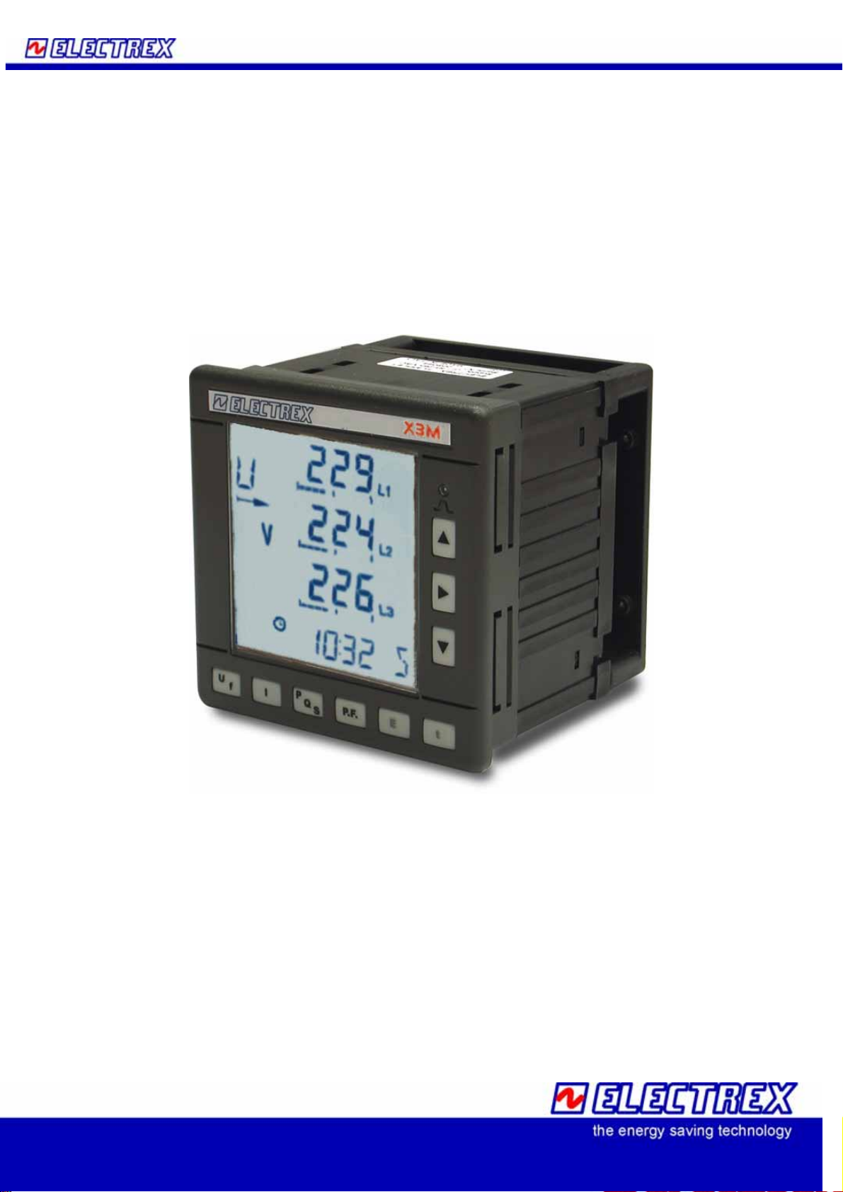
X3M
Energy Data Manager
User Manual
Version8 November 2005
The document can be modified without prior information.
1

Index
INTRODUCTION .............................................................................................................................. 6
1.1 COPYRIGHT ........................................................................................................................ 6
1.2 WARRANTY ......................................................................................................................... 6
1.3 RETURN AND REPAIR FORMALITIES................................................................................. 6
1.3.1 RE-SHIPPING OF REPAIRED PRODUCT..................................................................... 6
1.3.2 Return Material Authorization (RMA form).................................................................... 7
2 Safety......................................................................................................................................... 8
2.1 Operator safety .................................................................................................................... 8
3 Mounting .................................................................................................................................... 9
3.1 Dimensions (mm).................................................................................................................9
3.2 Fixing and blocking .............................................................................................................. 9
4 Wiring Diagrams ...................................................................................................................... 10
4.1 Power Supply..................................................................................................................... 10
4.2 Measurement Connections................................................................................................ 10
4.2.1 Voltage connection...................................................................................................... 10
4.2.2 Current connection...................................................................................................... 10
4.2.3 4W Star Connection (4 wires) ..................................................................................... 11
4.2.4 3W Delta Connection (3 wires).................................................................................... 12
4.2.4.1 L1 L3 Phase Connection with 2 CTs.................................................................. 12
4.2.4.2 L1 L2 Phase Connection with 2 CTs.................................................................. 13
4.2.5 2 Wire Connection (single phase) ............................................................................... 13
4.2.6 2 Wire Connection (double phase).............................................................................. 14
4.3 Output Connection............................................................................................................. 14
4.4 Connecting Optional Components..................................................................................... 15
4.4.1 RS485 Option.............................................................................................................. 15
4.4.2 RS232 Option.............................................................................................................. 16
4.4.3 Double 4-20 mA analogic Output Option..................................................................... 16
5 Instrument Use ........................................................................................................................ 17
5.1.1 Set up sequence ......................................................................................................... 18
5.1.2 Configuration Procedure ............................................................................................. 19
5.1.2.1 Electrical system configuration........................................................................... 19
5.1.2.2 Communication Parameters Configuration ........................................................ 21
5.1.2.3 Output Configuration .......................................................................................... 21
5.1.2.4 Pulse characteristics configuration..................................................................... 22
5.1.2.4.1 Pulse output set up with Modbus registers..................................................................... 22
5.1.2.5 Alarm Configuration ........................................................................................... 23
5.1.2.5.1 Alarm set up with Modbus registers. .............................................................................. 24
5.1.2.6 Analog 4-20 mA Outputs Configuration. ............................................................ 25
5.1.2.6.1 Analog output set up with Modbus registers................................................................... 26
5.1.2.6.2 4-20 mA output configuration of the average AVG values ............................................. 26
5.1.2.7 Clock calendar configuration (for X3M-D only) .................................................. 27
5.1.2.7.1 Clock set up with Modbus registers. ............................................................................... 28
5.1.2.7.2 Time zones ..................................................................................................................... 29
5.1.3 Reset Procedure ......................................................................................................... 33
5.2 Readings............................................................................................................................ 34
5.2.1 Readings selection keys.............................................................................................. 34
5.2.1.1 Voltage and Frequency Readings...................................................................... 34
5.2.1.1.1 3P 4 W Configuration...................................................................................................... 34
5.2.1.1.2 3P 3 W Configuration...................................................................................................... 35
5.2.1.1.3 3P-b 4W Configuration ................................................................................................... 35
5.2.1.1.4 3P-b 3W Configuration ................................................................................................... 35
5.2.1.1.5 1P 2W Configuration....................................................................................................... 35
5.2.1.1.6 2P 2W Configuration....................................................................................................... 35
5.2.1.2 Current readings ................................................................................................ 36
2

5.2.1.2.1
5.2.1.2.2 3P 3W Configuration....................................................................................................... 36
5.2.1.2.3 3P-b 4W Configuration ................................................................................................... 36
5.2.1.2.4 3P-b 3W Configuration ................................................................................................... 36
5.2.1.2.5 1P 2W and 2P 2W Configuration.................................................................................... 36
3P 4W Configuration....................................................................................................... 36
5.2.1.3 Powers ............................................................................................................... 37
5.2.1.3.1 3P 4W Configuration....................................................................................................... 37
5.2.1.3.2 3P 4W only Import Configuration.................................................................................... 37
5.2.1.3.3 3P 3W / 3P-b 3W / 2P 2W Configuration........................................................................ 38
5.2.1.3.4 3P-b 4W Configuration ................................................................................................... 38
5.2.1.3.5 1P 2W Configuration....................................................................................................... 38
5.2.1.4 P.F. Visualization ............................................................................................... 39
5.2.1.4.1 3P 4W Configuration....................................................................................................... 39
5.2.1.4.2 3Pb 4W Configuration..................................................................................................... 39
5.2.1.4.3 3P 3W e 3Pb 3W Configuration...................................................................................... 39
5.2.1.4.4 1P 2W e 2P 2W Configuration........................................................................................ 39
5.2.1.5 Energy................................................................................................................ 40
5.2.1.6 Only Import Energy Display ............................................................................... 40
5.2.1.7 Tariff Energies and Tariff Maximum Demand..................................................... 41
5.2.1.8 Calendar Clock and Life Time........................................................................... 41
6 Instrument Description............................................................................................................. 42
6.1 Introduction ........................................................................................................................ 42
6.2 Simplicity and versatility..................................................................................................... 43
6.3 Total harmonic distortion Measurement (THD).................................................................. 43
6.4 Energy Measurement......................................................................................................... 43
6.5 Storage .............................................................................................................................. 43
6.6 Calibration Led................................................................................................................... 44
6.7 Digital Outputs ................................................................................................................... 44
6.8 Pulse Output ...................................................................................................................... 44
6.9 Alarms................................................................................................................................ 44
6.10 Communication............................................................................................................... 44
6.11 Clock / Calendar ............................................................................................................. 45
6.11.1 Clock Format............................................................................................................ 45
6.12 Memory........................................................................................................................... 45
6.12.1 Dimensions .............................................................................................................. 45
6.12.2 Memory Read/Write. ................................................................................................ 45
6.12.3 File Structure............................................................................................................ 45
6.12.4 Record Structure...................................................................................................... 46
6.13 Average and peak Energy .............................................................................................. 46
6.14 Tariff Time Bands ........................................................................................................... 46
7 System Architecture................................................................................................................. 47
7.1 General Features............................................................................................................... 47
7.1.1 X3M.............................................................................................................................47
7.1.2 Options........................................................................................................................ 48
7.1.2.1 RS485 Port......................................................................................................... 48
7.1.2.2 RS232 Port......................................................................................................... 48
7.1.2.3 2 x 4-20 mA Analog Output................................................................................ 48
8 Parameters and formulas ........................................................................................................ 49
8.1 3P 4W Three phase with 4 wire neutral............................................................................ 49
8.1.1 Available Reading: ...................................................................................................... 49
8.1.2 Measurement Formulas: ............................................................................................. 51
8.2 3P 3W Three phase without neutral................................................................................... 53
8.2.1 Available Reading: ...................................................................................................... 53
8.2.2 Measurement Formulas: ............................................................................................. 55
8.3 3P-b 4W Balanced Three phase with neutral ................................................................... 57
8.3.1 Available Reading: ...................................................................................................... 57
8.3.2 Measurements Formulas:............................................................................................ 59
3

8.4 3P-b 3W Balanced three Phase without neutral 3 wires.................................................. 60
8.4.1 Available Reading: ...................................................................................................... 60
8.4.2 Measurement Formulas: ............................................................................................. 62
8.5 1P (2W) Single phase....................................................................................................... 63
8.5.1 Available Reading: ...................................................................................................... 63
8.5.2 Measurement Formulas: ............................................................................................. 65
8.6 2P (2W) Double phase...................................................................................................... 66
8.6.1 Available Reading: ...................................................................................................... 66
8.6.2 Measurements Formulas:............................................................................................ 68
8.6.3 Sampling: .................................................................................................................... 69
8.6.4 Grid frequency Measurement:..................................................................................... 69
8.7 Average values and energy Calculation. ........................................................................... 69
8.7.1 Energy counting .......................................................................................................... 69
8.7.2 Average Powers / maximum demand (m/Max) ........................................................... 69
9 MODBUS Protocol.................................................................................................................. 70
9.1 Foreword:........................................................................................................................... 70
9.2 “Device dependent” Functions........................................................................................... 71
9.2.1 (0x11) Slave ID Report................................................................................................ 71
9.2.2 (0x07) Exception Status Read..................................................................................... 72
9.3 “User defined” Functions.................................................................................................... 72
9.3.1 (0x42) Slave Address Change .................................................................................... 72
9.4 Register Mapping............................................................................................................... 73
9.4.1 Holding registers ......................................................................................................... 73
9.4.2 Parameter selection tables.......................................................................................... 80
9.4.3 X3M Input registers ..................................................................................................... 84
9.4.4 Input Registers (backward compatibility area) ............................................................ 88
9.4.5 Coils (back compatibility)............................................................................................. 91
9.4.6 X3M coils..................................................................................................................... 91
10 File organization and management in the X3M flash memory. ............................................ 92
10.1 File system .....................................................................................................................92
10.1.1 Types of file.............................................................................................................. 94
10.1.2 File structure ............................................................................................................ 95
10.1.3 Structured Files........................................................................................................ 95
10.1.4 Descriptors............................................................................................................... 96
10.1.5 Homogenous files .................................................................................................. 103
10.1.6 Non Homogeneous files......................................................................................... 106
10.2 Type 0 files ................................................................................................................... 107
10.2.1 File status............................................................................................................... 108
10.2.2 Service status......................................................................................................... 108
10.3 Type 1 files ................................................................................................................... 109
10.3.1 Service configuration.............................................................................................. 110
10.4 Type 4 files ................................................................................................................... 112
10.4.1 Service Configuration............................................................................................. 114
10.4.2 Example of configuration file: “Events.xmbf”.......................................................... 116
10.4.3 Type 5 files............................................................................................................. 118
10.4.4 Service configuration.............................................................................................. 119
10.4.5 Example of configuration file: “Peaks.xmbf”........................................................... 120
10.5 Type 7 files ................................................................................................................... 121
10.5.1 Service configuration.............................................................................................. 121
10.5.2 Reset...................................................................................................................... 122
10.5.3 Example of configuration file: “EnergyCounters.xmbf”........................................... 123
10.6 Type 8 files ................................................................................................................... 124
10.6.1 Service configuration.............................................................................................. 124
10.6.2 Reset...................................................................................................................... 125
10.6.3 Example of configuration file: “MaximumDemands.xmbf”...................................... 126
10.6.4 Clock / Calendar..................................................................................................... 127
4

10.6.4.1 Timezones........................................................................................................ 127
10.6.4.2 Files.................................................................................................................. 128
10.6.4.3 Clock related Modbus registers........................................................................ 128
10.6.5 Upgrading the firmware.......................................................................................... 129
11 The XMBF.EXE utility (Electrex ModBus File) ................................................................... 130
11.1 Commands for PC handling of the files of the X3M memory........................................ 130
11.1.1 Short commands.................................................................................................... 131
11.2 Operation type .............................................................................................................. 131
11.2.1 --read Download............................................................................................... 131
11.2.2 --write Upload .................................................................................................. 131
11.2.3 --del Delete....................................................................................................... 132
11.2.4 --create Create................................................................................................. 132
11.2.5 --reboot Instrument restart from zero.............................................................. 132
11.3 Communication port ..................................................................................................... 132
11.3.1 IP Address.............................................................................................................. 132
11.3.2 Com Port................................................................................................................ 132
11.4 Protocol format ............................................................................................................. 132
11.5 Address ........................................................................................................................ 132
11.6 File number................................................................................................................... 132
11.7 File Name ..................................................................................................................... 133
11.8 Destination.................................................................................................................... 133
11.8.1 --dpath=DestinationPath..................................................................................... 133
11.8.2 --dfile=DestinationFileName............................................................................. 133
11.9 Output format................................................................................................................ 134
11.9.1 TXT Output............................................................................................................. 134
11.9.2 Print to screen........................................................................................................ 134
11.9.3 HEX output............................................................................................................. 134
11.9.4 HTML Output.......................................................................................................... 136
11.9.5 XLS output type...................................................................................................... 138
11.10 Application examples ................................................................................................ 140
11.10.1 Changing the readings stored by Service (1) Load Profiles............................. 140
11.10.2 Changing the thresholds of Service (4) Events................................................ 143
11.10.3 Changing the parameters stored by Service (5) Peaks ................................... 146
12 Technical Characteristics ................................................................................................... 148
13 Firmware Revisions............................................................................................................ 150
14 Order codes ....................................................................................................................... 150
15 DECLARATION OF CONFORMITY .................................................................................. 150
5

INTRODUCTION
We thank you for choosing an Electrex instrument
We invite you to carefully read this instructions manual for the best use of the X3M instruments.
1.1 COPYRIGHT
Electrex S.r.l. All rights are reserved.
It is forbidden to duplicate, adapt, transcript this document without Electrex written authorization, except
when regulated accordingly by the Copyright Laws.
Copyright© 2003-2004
1.2 WARRANTY
This product is covered by a warranty against material and manufacturing defects for a period of 36 months
period from the manufacturing date
The warranty does not cover the defects that are due to:
• Negligent and improper use
• Failures caused by atmospheric hazards
• Acts of vandalism
• Wear out of materials
Electrex reserves the right, at its discretion, to repair or substitute the faulty products
The warranty is not applicable to the products that will result defective in consequence of a negligent and
improper use or an operating procedure not contemplated in this manual.
1.3 RETURN AND REPAIR FORMALITIES
Electrex accepts the return of instruments for repair only when authorized in advance. For instrument
purchased directly, the repair authorization must be requested to Electrex directly by using the enclosed
RMA form. We recommend otherwise to contact your local distributor for assistance on the return/repair
formalities. In both the cases, the following information must be supplied:
• Company full data
• Contact name for further communication
• Product description
• Serial number
• Description of the returned accessories
• Invoice / Shipping document number and date
• Detailed description of the fault and of the operating condition when the fault occurred
The Electrex repair lab will send the authorization number to the customer directly or to the distributor as per
applicable case.
The RMA authorization number shall be clearly marked on the packaging and on the return transport
document.
WARNING: Failure to indicate the RMA number on the external packaging will entitle our warehouse to
refuse the delivery upon arrival and to return the parcel at sender’s charge.
The material must be shipped:
- within 15 working days from the receipt of the return authorization number
- free destination i.e. all transport expenses at sender’s charge.
- to the following address: Electrex S.r.l.
Atn. Repair laboratory
- the units covered by warranty must be returned in their original packaging.
1.3.1 RE-SHIPPING OF REPAIRED PRODUCT
The terms for re-shipment of repaired products are ex-works, i.e. the transport costs are at customer charge.
Products returned as detective but found to be perfectly working by our laboratories, will be charged a fixed
fee (40.00 Euro + VAT where applicable) to account for checking and testing time irrespective of the
warranty terms.
Via Claudia 96 - 41056 Savignano s/P (MO) - Italy
6

1.3.2 Return Material Authorization (RMA form)
Request for the authorization number for the return of goods
Date:
Company:
Contact name:
TEL: FAX:
Product description:
Serial number:
Description of the returned accessories (if any):
Original purchase Invoice (or Shipping document) number and date.
NB: The proof of purchase must be provided by the customer. Failure to complete this area will automatically void all warranty.
Detailed description of the malfunction and of the operating conditions when the fault occurred
Tick off for a quotation
Should a product be found by our laboratories to be perfectly working, a fixed amount of 40 E uro (+VAT if applicable) will be charged
to account for checking and testing time irrespective of the warranty tems.
Space reserved to ELECTREX
R.M.A. No.
The RMA number shall be clearly indicated on the external packaging and on the shipping document:. Failure to observe this
requirement will entitle the ELECTREX warehouse to refuse the delivery.
7

2 Safety
This instrument was manufactured and tested in compliance with IEC 61010 class 2 standards for operating
voltages up to 250 VAC rms phase to neutral.
In order to maintain this condition and to ensure safe operation, the user must comply with the indications
and markings contained in the following instructions:
• When the instrument is received, before starting its installation, check that it is intact and no damage
occurred during transport.
• Before mounting, ensure that the instrument operating voltages and the mains voltage are
compatible then proceed with the installation.
• The instrument power supply needs no earth connection.
• The instrument is not equipped with a power supply fuse; a suitable external protection fuse must be
foreseen by the contractor.
• Maintenance and/or repair must be carried out only by qualified, authorized personnel
• If there is ever the suspicion that safe operation is no longer possible, the instrument must be taken
out of service and precautions taken against its accidental use.
• Operation is no longer safe when:
1) There is clearly visible damage.
2) The instrument no longer functions.
3) After lengthy storage in unfavorable conditions.
4) After serious damage occurred during transport
The instruments must be installed in respect of all the local regulations.
2.1 Operator safety
Warning: Failure to observe the following instructions may lead to a serious danger of death.
- During normal operation dangerous voltages can occur on instrument terminals and on
voltage and current transformers. Energized voltage and current transformers may generate
lethal voltages. Follow carefully the standard safety precautions while carrying out any
installation or service operation.
- The terminals of the instrument must not be accessible by the user after the installation. The
user should only be allowed to access the instrument front panel where the display is
located.
- Do not use the digital outputs for protection functions nor for power limitation functions. The
instrument is suitable only for secondary protection functions.
- The instrument must be protected by a breaking device capable of interrupting both the
power supply and the measurement terminals. It must be easily reachable by the operator
and well identified as instrument cut-off device.
- The instrument and its connections must be carefully protected against short-circuit.
Precautions: Failure to respect the following instructions may irreversibly damage to the instrument.
- The instrument is equipped with PTC current limiting device but a suitable external protection
fuse should be foreseen by the contractor.
- The outputs and the options operate at low voltage level; they cannot be powered by any
unspecified external voltage.
- The application of currents not compatible with the current inputs levels will damage to the
instrument.
8
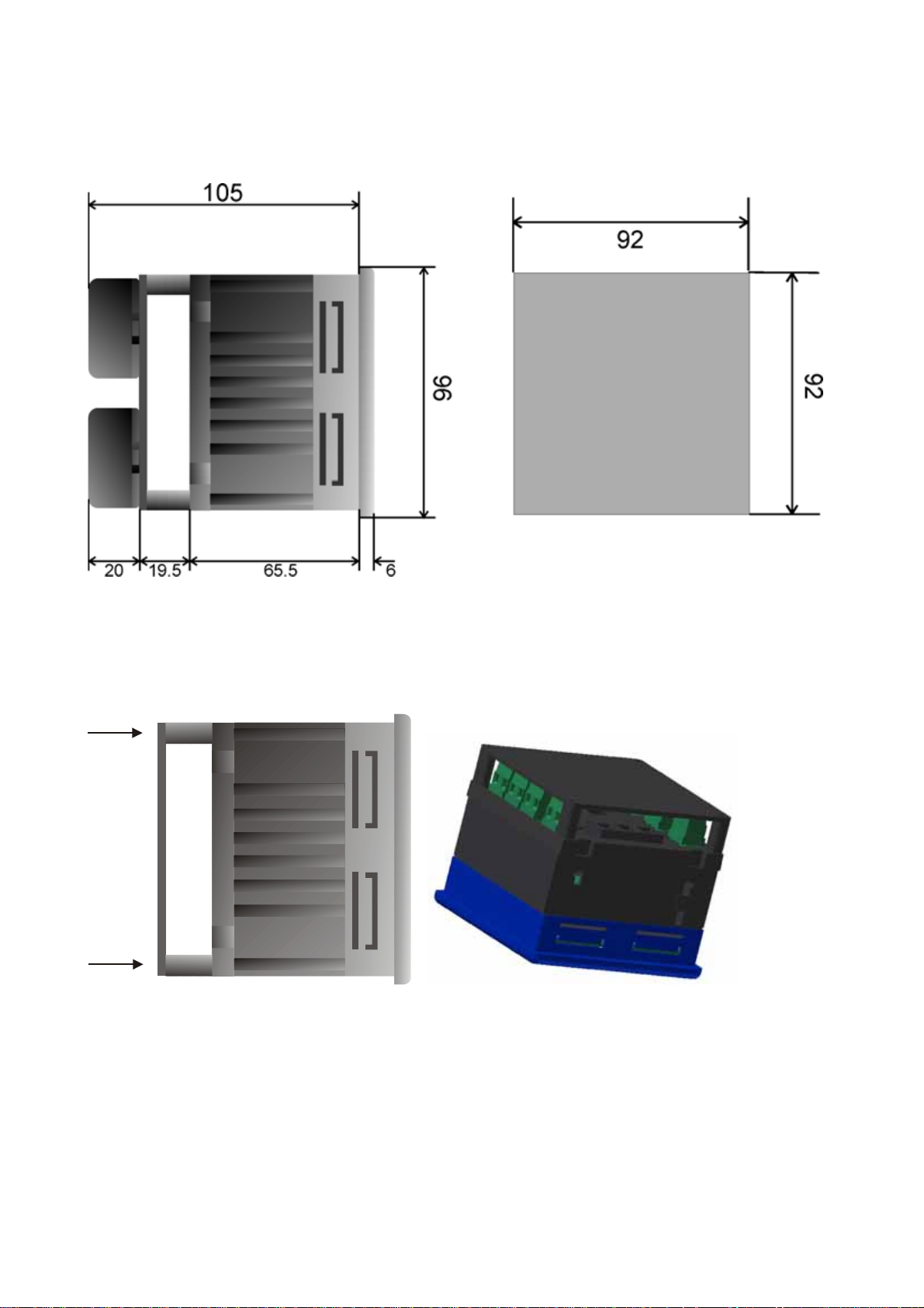
3 Mounting
3.1 Dimensions (mm)
3.2 Fixing and blocking
The connection terminals of the instrument are held in place by a plastic panel, which must be mounted
using 4 screws (supplied). This set up will prevent the disconnection of the current measurement terminals.
9
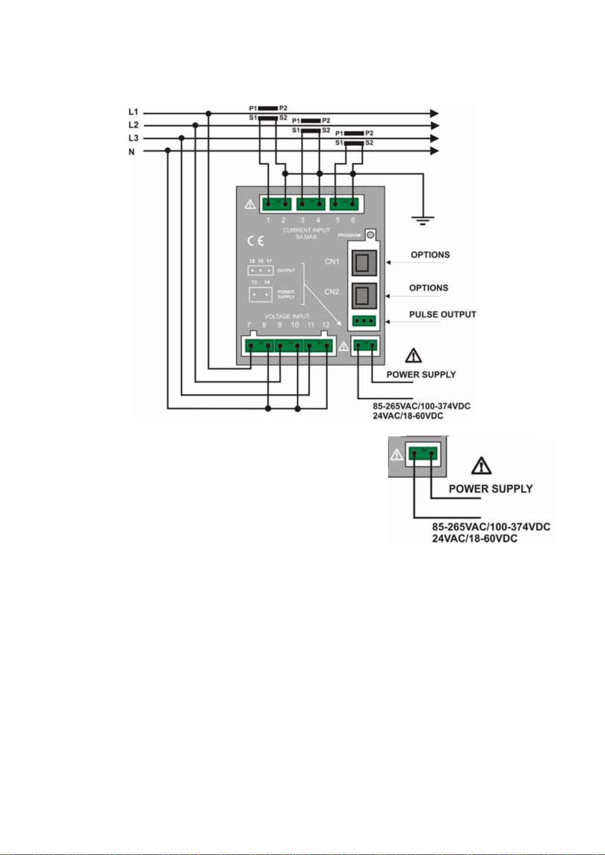
4 Wiring Diagrams
4.1 Power Supply
The instrument is fitted with a separated power supply with extended
functioning range. The terminals for the power supply are numbered
(13 and 14). Use cables with max cross-section of 4 mm
2
.
4.2 Measurement Connections
4.2.1 Voltage connection
Use cables with max cross-section of 4 mm2 and connect them to the terminals marked VOLTAGE INPUT
on the instrument according to the applicable diagrams that follow.
4.2.2 Current connection
It is necessary to use external CTs with a primary rating adequate to the load to be metered and with a 5A
secondary rating. The number of CTs to be used (1, 2 or 3) depends upon the type of network.
Connect the CT output(s) to the terminals marked CURRENT INPUT of the instrument according to the
applicable diagrams that follow.
Use cables with cross-section adequate to the VA rating of the CT and to the distance to be covered. The
max cross-section for the terminals is 4 mm
N.B. The CT secondary must always be in short circuit when not connected to the instrument in order to
avoid damages and risks for the operator.
Warning: THE PHASE RELATIONSHIP AMONG VOLTAGE AND CURRENT SIGNALS MUST BE
CAREFULLY RESPECTED. ALL DISREGARD OF THIS RULE OR OF THE WIRING DIAGRAM
LEADS TO SEVERE MEASUREMENT ERRORS.
2
.
10

4.2.3 4W Star Connection (4 wires)
Low voltage 3 CTs Average or high voltage 3 TCs 3 CTs
Configuration 3P 4W Configuration 3P 4W
Low Voltage 1 CT (balanced and symmetric)
Configuration 3P-b 4W
11
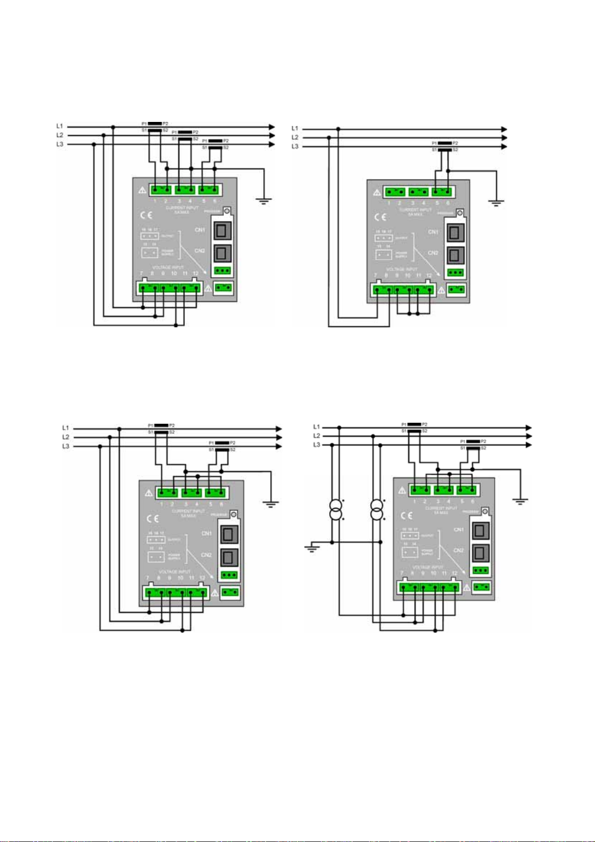
4.2.4 3W Delta Connection (3 wires)
Connection with 3 CTs Connection with 1CT
Low Voltage 3 CTs Low Voltage 1 CT
3P 3W Configuration 3P-b 3W Configuration
(Balanced and symmetric)
4.2.4.1 L1 L3 Phase Connection with 2 CTs
Low Voltage Average or High Voltage
3P 3W Configuration 3P 3W Configuration
12

4.2.4.2 L1 L2 Phase Connection with 2 CTs
Low Voltage 2 CTs Average or High Voltage 2 CTs 2 TCs
3P 3W Configuration 3P 3W Configuration
4.2.5 2 Wire Connection (single phase)
Low Voltage Neutral phase 1 Ct
1P 2W Configuration
13
4.2.6 2 Wire Connection (double phase)
×
Low Voltage phase 1 CT
2P 2W Configuration
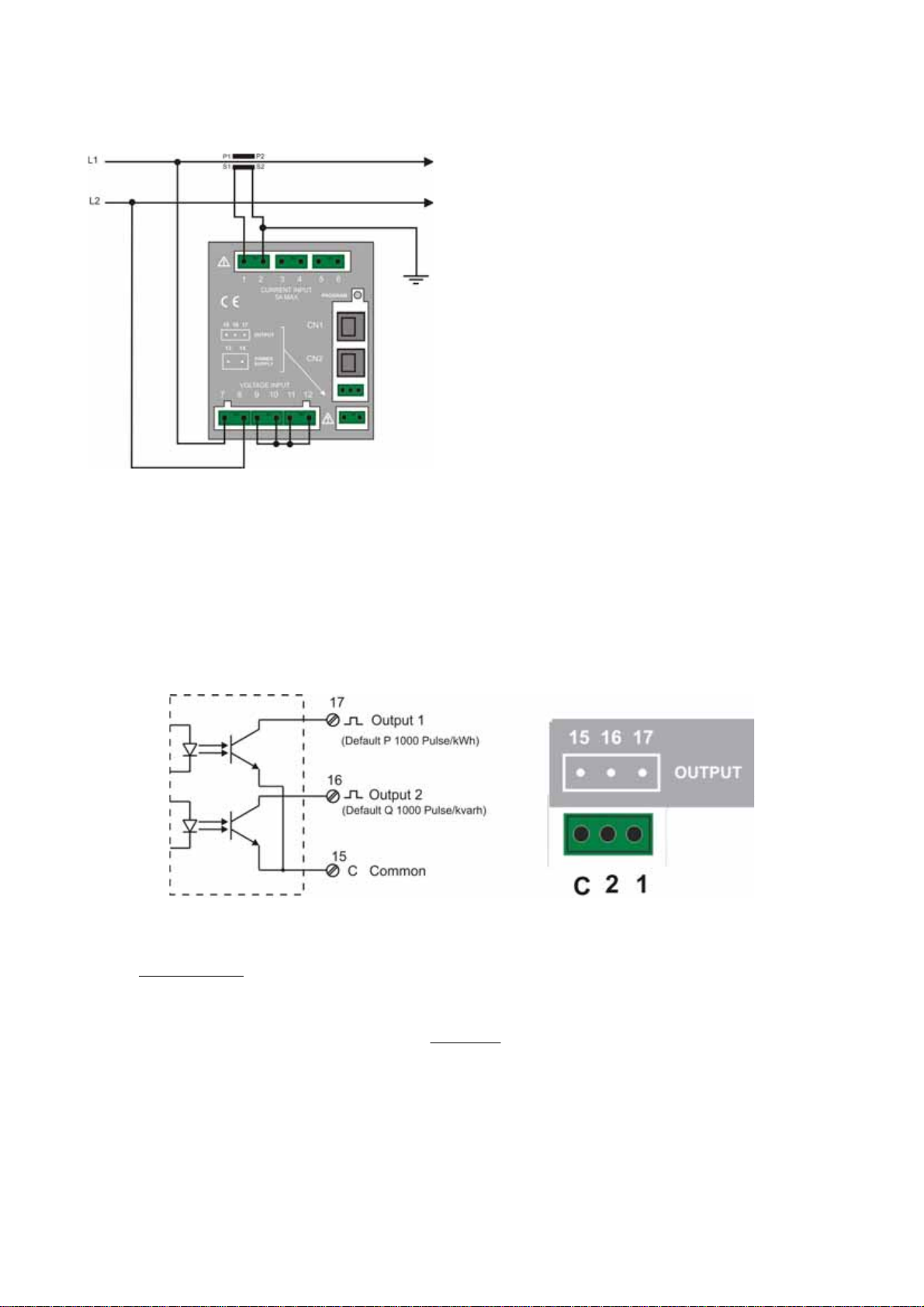
4.3 Output Connection
The instrument is equipped with two opto-isolated transistor outputs rated 27 Vdc, 27 mA (DIN 43864
standards).
The outputs working mode is set by default to operate as pulse output proportional to the Active energy
(output 1) and to the Reactive energy (output 2). They support an output rate of 1.000 pulses per kWh (or
kvarh) referred to the instrument input range without any CT and PT multiplier.
In order to calculate the energy value of each pulse the following formula must be considered.
KK
×
PTCT
K
=
P
Example: CT = 100/5; PT = 20.000/100
Other pulse rate settings may be however programmed as described in the instrument set up section.
The operating mode of the digital outputs may also be changed to work as alarm output or as remote output
device controlled by the Modbus protocol as described in the instrument set up section.
/
kWhPulse
Where: K
= energy of each pulse; KCT = CT ratio ; K
p
Pulse/kWh = Pulse rate
20020
=
P
1000
=
pulsekWhK
/4
= PT ratio ;
PT
or kWh = Pulse count / 4
14
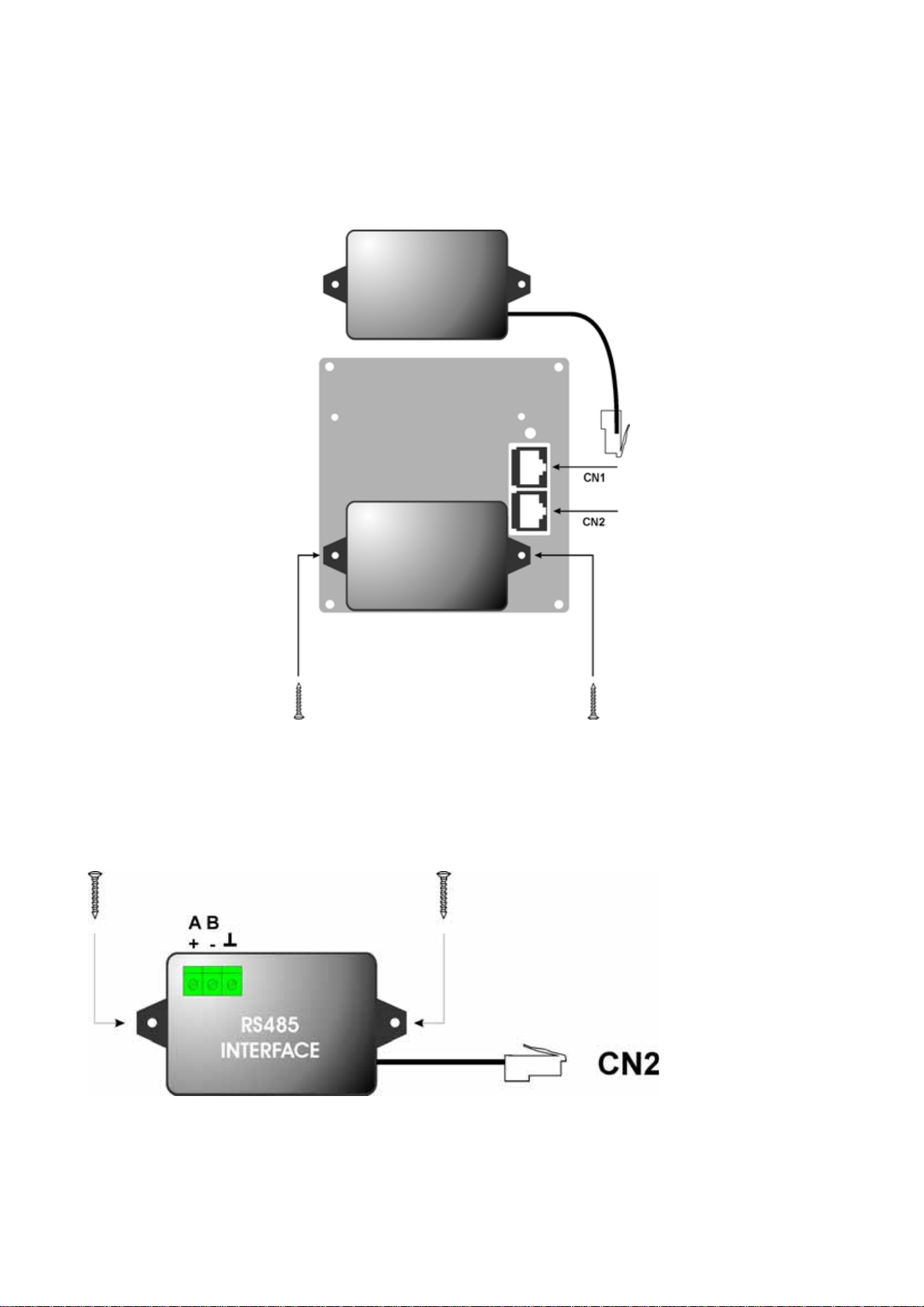
4.4 Connecting Optional Components
The optional components of X3M are assembled on the back panel of the instrument, where the RJ45
connectors are located
The optional component feature settings are only displayed when one of them is connected to the instrument
CN1 = 4-20 mA module or Hardware key
CN2 = RS485 or RS232 interface
4.4.1 RS485 Option
15
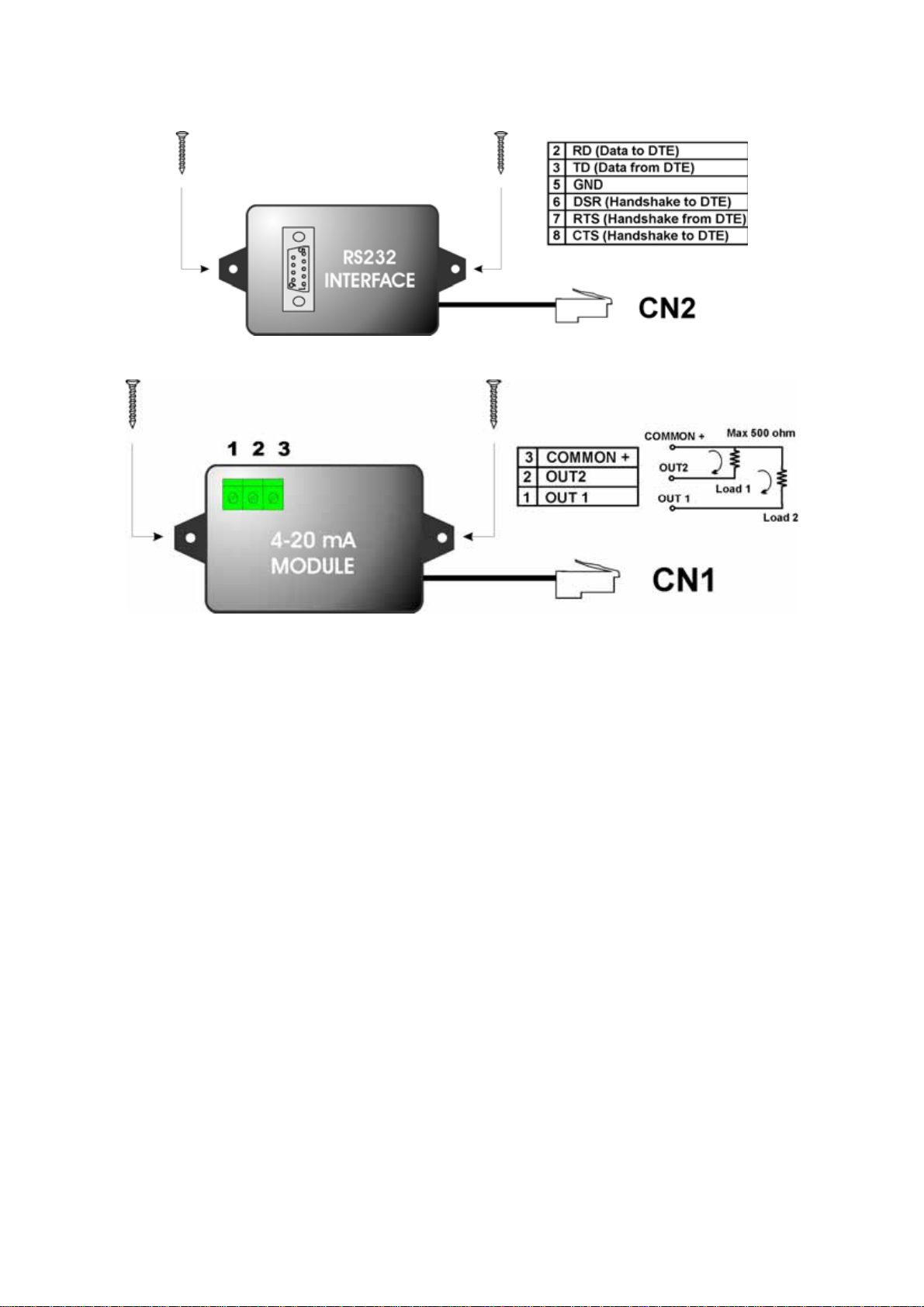
4.4.2 RS232 Option
4.4.3 Double 4-20 mA analogic Output Option
Self powered output, do not use external power supply.
16
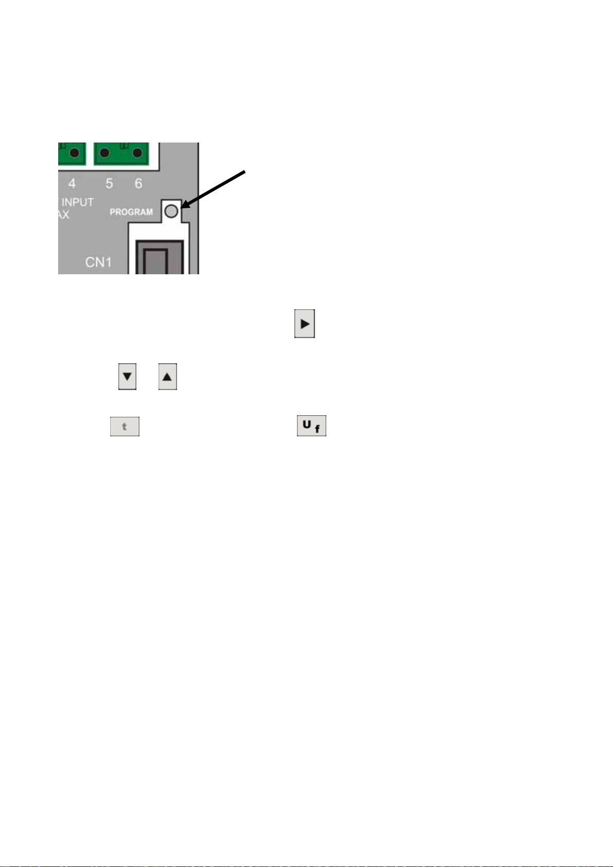
5 Instrument Use
The programming procedure allows to vary the instrument functioning parameters.
You can enter the procedure with the button Program located at the back of the instrument.
In this environment, you can enter the measurement parameters and the network configuration.
The various fields can be selected by pressing the
button which also allows navigating to all the Setup
pages
Pressing the
and buttons you can modify the selected input fields (flashing)
The content of a field can be either numeric or a parameter controlling the device behavior.
The button
advances to the next page, while selects the previous page
By pressing the button PROGRAM (while in any configuration page) the menu is exited and the configuration
saved.
17
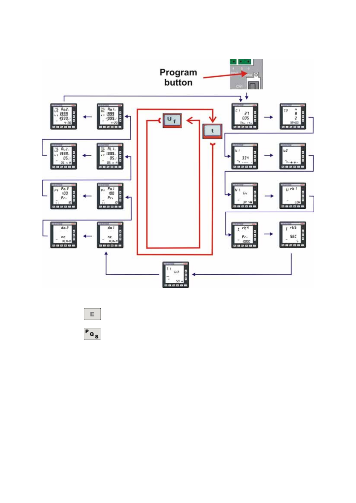
5.1.1 Set up sequence
Within the first page of the instrument set up menu, the following functions are available too.
- a pressure of the
- a pressure of the
Here below the page format and the programming flow.
key opens the energy counters reset page.
key opens the reset page of the average and maximum demand.
NOTE: all the modifications to the instrument programming parameters are effective
only when you exit the programming page pressing the PROGRAM button located
on the instrument rear panel.
18
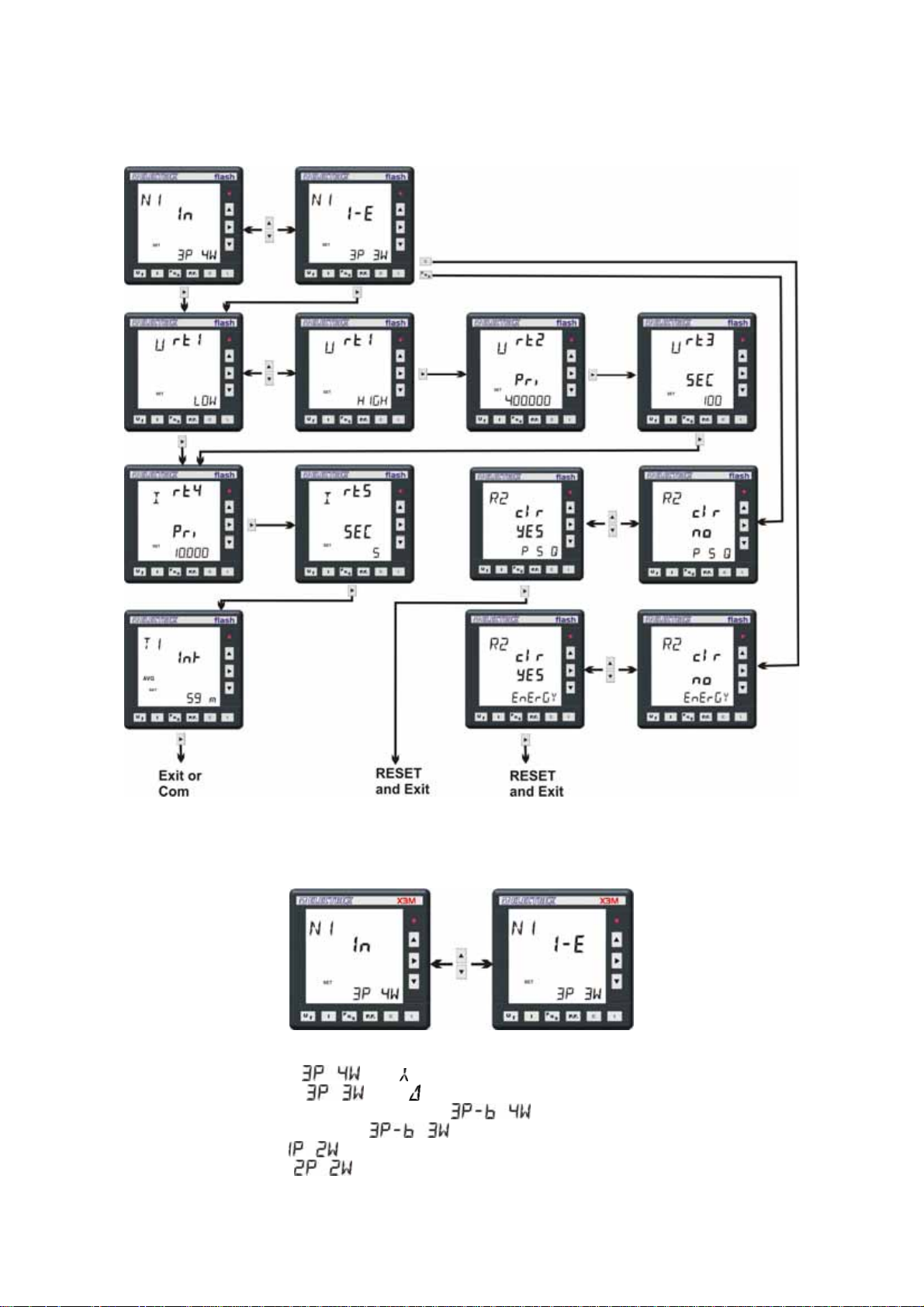
5.1.2 Configuration Procedure
5.1.2.1 Electrical system configuration
The first programming page shows the configuration of the type of electrical system.
The first selection sets the type of electrical system and the type of wiring used:
• 3 phase 4 wire system
• 3 phase 3 wire system
• balanced 3 phase 4 wire system (1 CT only)
• balanced 3 phase 3 wire system
• single phase system
• double phase system
, Star ,
, delta ,
,
,
.
The second selection sets whether the operating mode is:
19
• Import only user
• Import-Export system
The instrument is set by default to
CTs connection errors
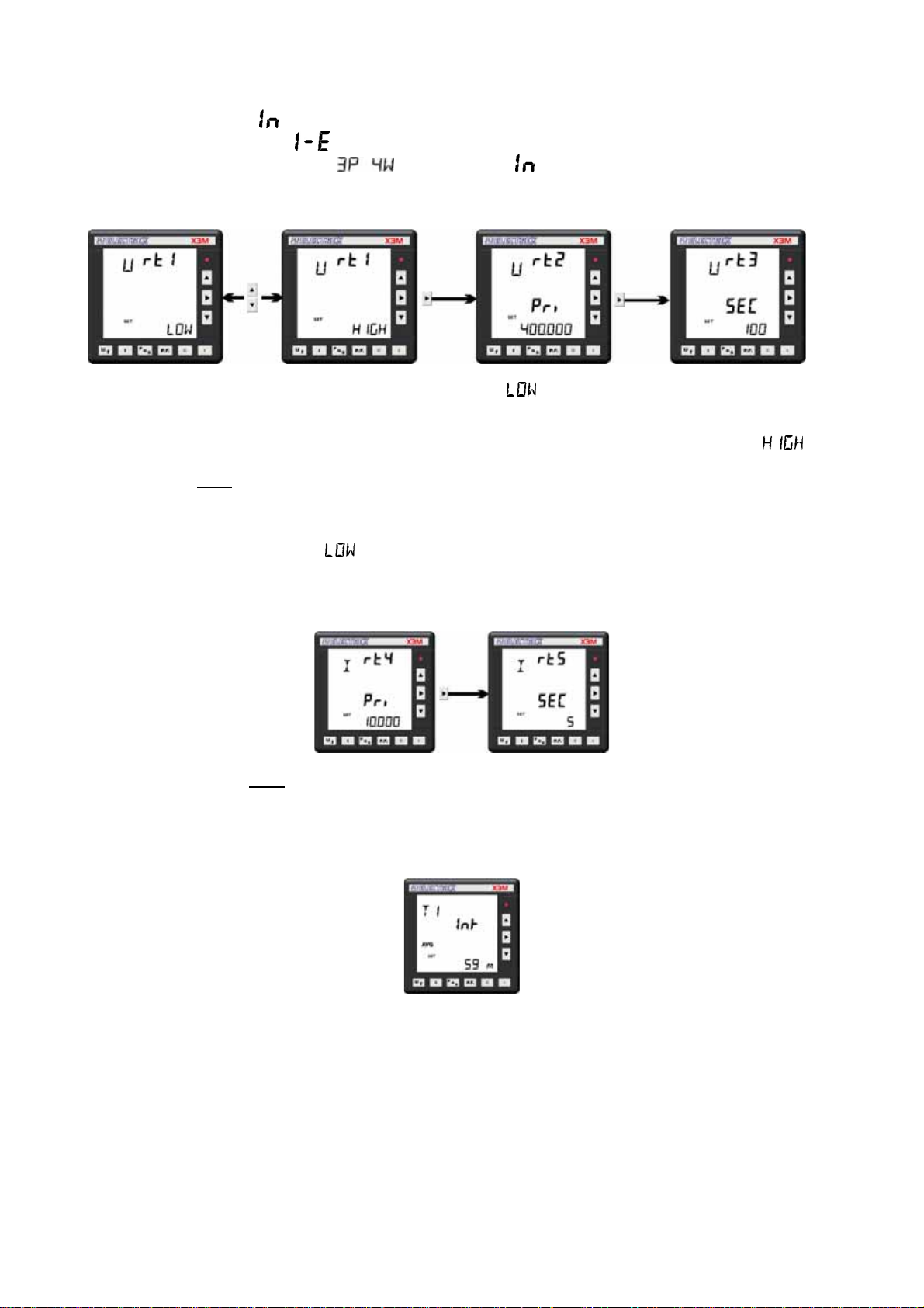
The following page enables to set the type of voltage measurement.
.
and Import only mode. and automatically corrects possible
If the voltage measurement is direct in low voltage, select
setting page.
If the voltage measurement is made on the HT side and/or via a voltage transformer, select
proceed to the next page for setting the Volatge transformer (PT) primary and secondary values
Enter the PT rated
measurement are unsuitable to this purpose.
The primary and the secondary values must be integers, the ratio can also be fractional.
The instrument is set by default to
After the voltage setting, the current set up page is prompted for programming the CT values; it requires the
entry of the CT primary rating and the CT secondary rating.
Ensure to enter the CT rated
When using 2 or 3 current transformers ensure that all the current transformers have the same ratings.
The instrument is set by default to [
The next page allows to set the integration time for calculating the Average and the Maximum Demand.
primary and secondary values indicated on the PT label; the values taken by
primary and secondary values as indicated on the CT label.
00005/5].
; the menu passes directly to the currents
and
The value is expressed in minutes in a 1 to 60 min. range.
The instrument supports two average values: one calculated by using the sliding window method and the
other one calculated on a fixed time basis. The time setting that is programmed by keyboard is the average
demand integration time with the sliding window method. The Maximum Demand too is calculated on the
sliding window basis.
The integration time on a fixed time basis is used for storing the energy data however this setting is available
only as a MODBUS register via serial port setting.
20
5.1.2.2 Communication Parameters Configuration
This menu appear only upon connection to the instrument of an RS-485 or an RS-232 optional module.
The setting of the RS485 communication characteristics requires to scroll the programming pages with two
keys;
The
key advances to the next page, the key returns to the previous page
The first page is the following:
This page enables the setting of respectively:
- communication speed
- number of data bits
- parity
- stop bits
All these data are correlated depending upon the stop bit value.
Additional parameters regarding the MODBUS communication protocol may be
set in the next page:
- Mode: it may be configured to RTU or to ASC (ASCII) mode.
- Slave Address
- Transmission delay; it stands for the time delay the instrument will wait prior
to reply to a data query. It is expressed in milliseconds, the default value is
100 msec and a 0 setting is also possible.
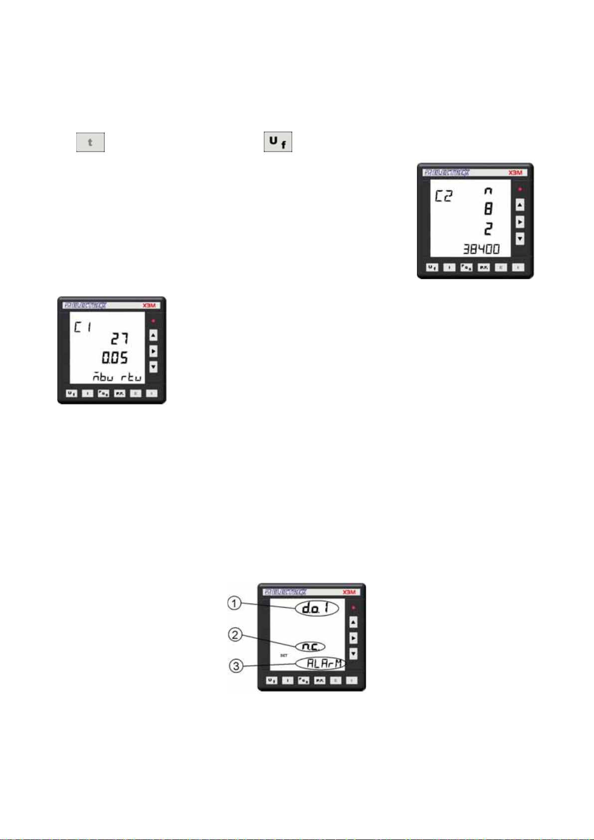
5.1.2.3 Output Configuration
The instrument is equipped with 2 digital outputs that are set by default to operate as pulse outputs
proportional to P
instrument range without any CT and PT multiplier.
The operating mode of digital outputs may be changed to operate as alarm output or as remote output
device controlled by the Modbus protocol.
When operating on the Modbus protocol, in order to ensure a protection to the outputs in case of
communication failure, it is possible to configure a watchdog timer (programmable from 0 to 60 minutes; 0 =
disabled).
The following entry fields are prompted (example for output 1):
(output 1) and Q∑ (output 2) at a rate of 1.000 pulses per kWh (or kvarh) referred to the
∑
(1) Digital out number being programmed.
(2) Contact: it configures the rest state of the output transistor.
n.c. normally closed or n.o. normally open:
(3) Mode of operation:
PULSE (default setting) for operation as pulse output
21
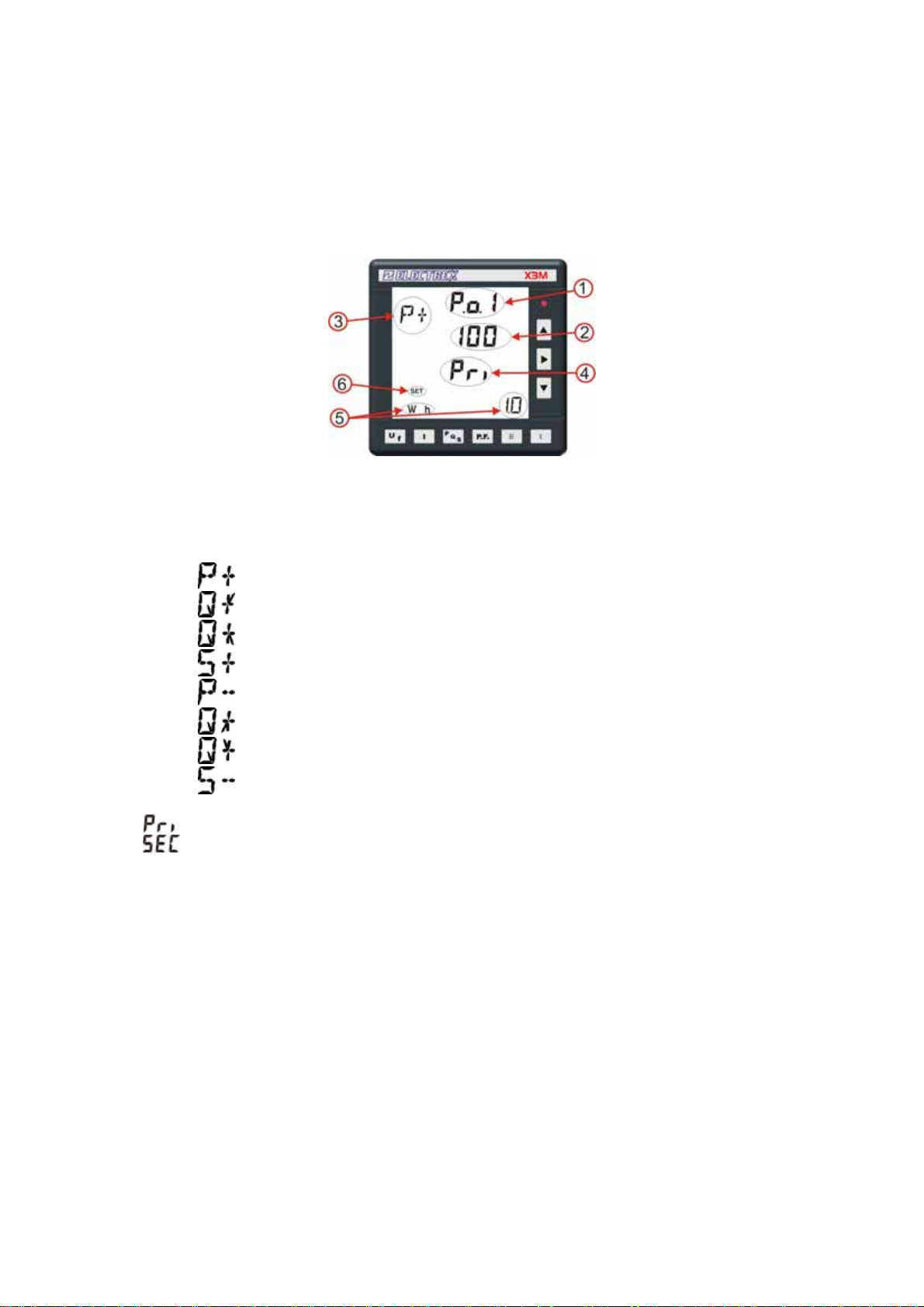
ALARM for operation as alarm contact output
REM Remote for operation as remote output device controlled via Modbus
5.1.2.4 Pulse characteristics configuration
If the PULSE selection is operated, the following page is shown allowing the configuration of the pulse
characteristics:
Where:
(1) Pulse output number being programmed.
(2) Pulse duration in mSec; programmable from 50 up to 900 in steps of 10
(3) Identifies the quantity proportional to the pulse output, selecting among:
Imported Active Power (import)
Inductive reactive Power with imported Active Power
Capacitive reactive Power with imported Active Power
Apparent Power with imported Active Power
Exported Active Power (export)
Inductive reactive Power with exported Active Power
Capacitive reactive Power with exported Active Power
Apparent Power with exported Active Power
(4)
the pulses take into account the CT and PT ratio and are referred to their primary readings
the pulses are referred to the CT (and PT) secondary reading without any multiplier .
(5) Pulse weight: programmable from 0,1 Wh up to 1 MWh through all the intermediate steps.
Example: 1.0 Wh = 1000 pulses/kWh.
(6) Identifies SETUP.
5.1.2.4.1 Pulse output set up with Modbus registers.
To set up the pulse output the Modbus Holding Registers from 120 to 127 have to be used.
Refer to chapter 9 for the details.
22
5.1.2.5 Alarm Configuration
The Instrument is equipped with two alarms that are triggered by a programmable threshold on anyone of
the measured parameters.
The types of alarm available are: maximum, minimum and 1-of-3.
A minimum alarm is triggered when the selected parameter is lower than the alarm threshold.
A maximum alarm is triggered when the selected parameter exceeds the alarm threshold.
A 1-of-3 alarm is triggered when anyone of the phase readings, whichever the phase involved, trespasses
the alarm threshold – this alarm can be either maximum or minimum. On a 1-of-3 current alarm, the
threshold is expressed as percentage (rather than a value) that stands for the unbalance between the
phases. The alarm therefore triggers when the percent difference between two of the three phases exceeds
the threshold; it is calculated as 100 x (I
All alarms allow also the setting of an hysteresys and a delay time.
The hysteresys (in percent) sets the difference between the triggering threshold and the end threshold (this
prevents repeated alarm triggering when the reading oscillates around the trigger value). Example: a 5%
hysteresys on a threshold of 100, triggers the alarm when the reading exceeds 100 but it will switch off the
alarm when the reading becomes lower than 95.
The delay time sets a time delay for triggering on the alarm after its actual occurrence (or triggering off after
its actual end).
The alarm setup procedure is activated from the output configuration screen or at the end of page
max
– I
min
)/I
max
.
configuration using the
button or the button.
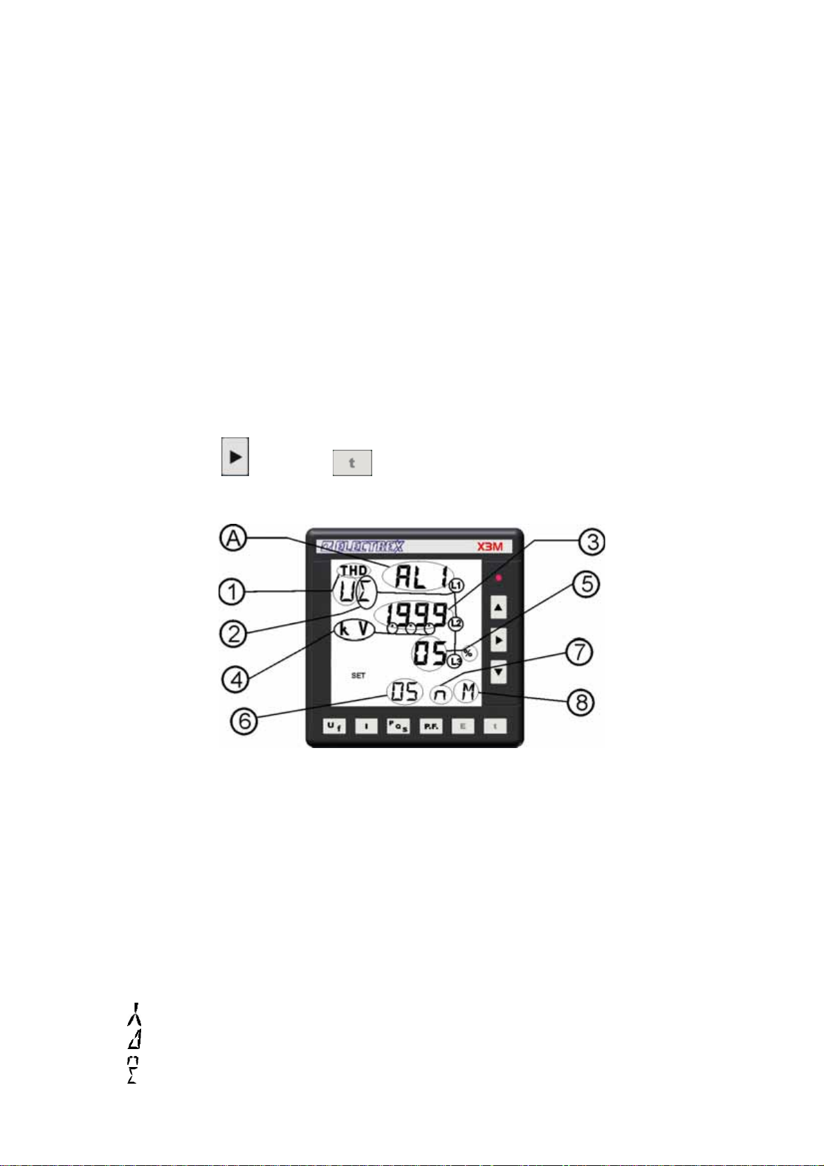
The fields meaning of Alarm 1 is as follows:
(A) Alarm No. identification (AL1 = alarm 1 that may be associated to output 1)
(1)Parameter type applying to Alarm 1. The possible choices are:
-- Disabled
U Voltage
f Frequency
I Current
P Active Power
Q Reactive Power
S Apparent Power
λ (PF) Power Factor
THD
U
THD
Total Harmonic Distortion (current)
I
Total Harmonic Distortion (voltage)
(2) Quantity definition: The possible definitions are:
Average star value (voltage, current and THD only).
Average system voltage (voltage and voltage THD only)
Neutral value (current only)
Three phase power (only on active, reactive, apparent power)
23

L1 Phase 1 quantity.
L2 Phase 2 quantity.
L3 Phase 3 quantity.
L1-L2 Phase L1 phase L2 value (Phase to phase Voltages and THD only)
L2-L3 Phase L2 phase L3 value (Phase to phase Voltages and THD only)
L3-L1 Phase L3 phase L1 value (Phase to phase Voltages and THD only)
1di 3
Alarm on all three phases. The symbols L1-L2, L2-L3 and L3-L1 are flashing
(voltage and THD only).
1di 3
AVG Alarm on average powers.
(3)Threshold voltage: programmable in the range –1999 +1999
(4)Decimal point position. The quantity can be scaled by powers of ten by using the m, K, M symbols
and the decimal point. Range is between 10-3 and 109.
(5)Hysteresis value, from 0% to 99%
(6)Latency time, from 0 to 99 seconds
(7)Output trigger type. n=normal (the relay is active for the duration of the alarm), p=pulsed (the alarm
triggering generates a pulse).
(8) Alarm type: M=max; m=min
The procedure for alarm 2 is identical.
Alarm on all the three phases. The symbols L1, L2 and L3 are flashing
(voltage,current and THD only).
5.1.2.5.1 Alarm set up with Modbus registers.
To set up the alarm t the Modbus Holding Registers from 95 to 106 have to be used.
Refer to chapter 9 for the details.
24
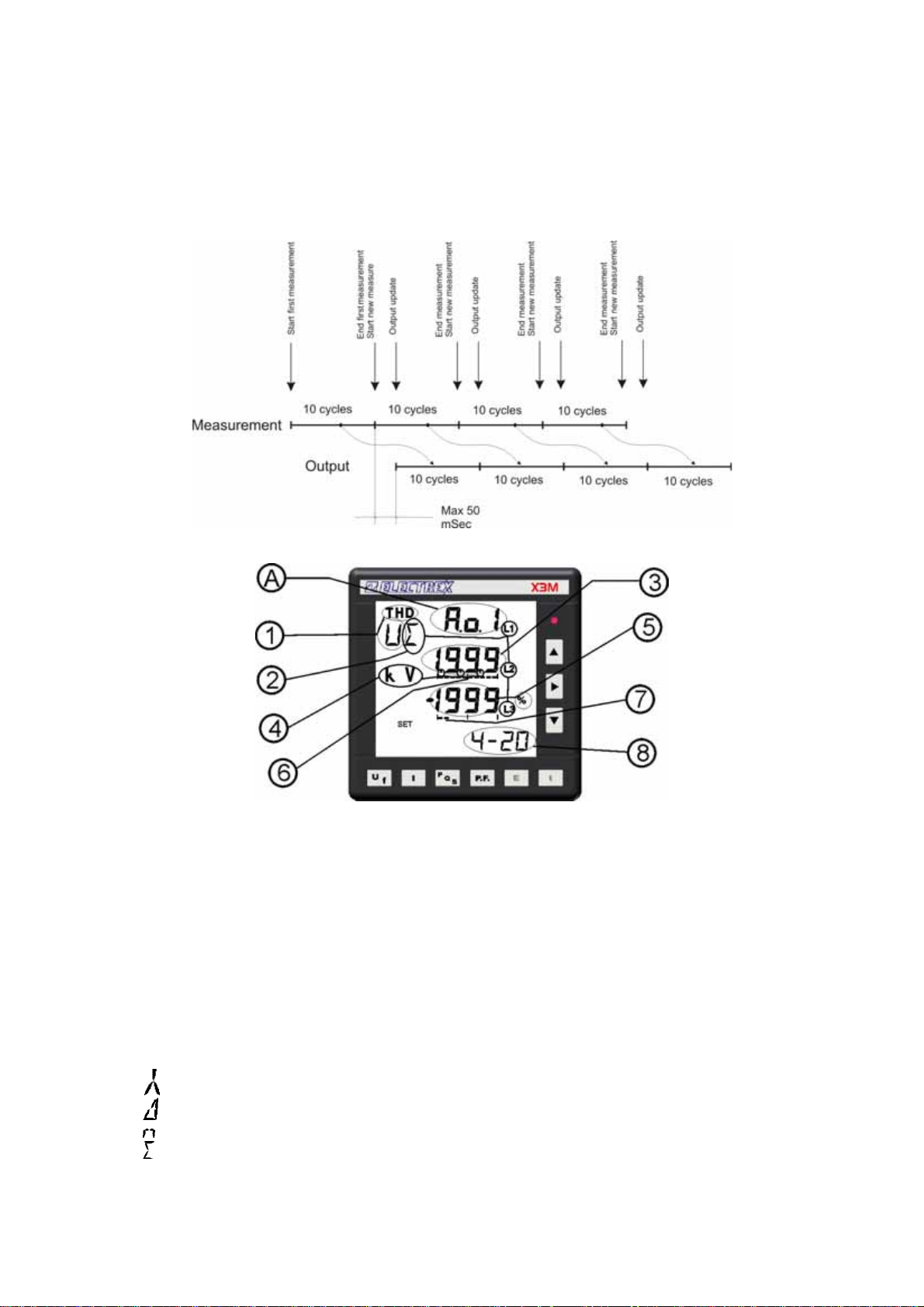
5.1.2.6 Analog 4-20 mA Outputs Configuration.
The instrument supports two 4-20 mA or 0-20 mA analog outputs with 500 ohms maximum load. Each output
is to one of the parameters handled by the instrument.
The output is updated every 10 cycles of the network frequency (i.e. every 200mSec with 50 Hz mains) with
a maximum delay of 50 mSec from the actual measurement.
(A)Output identification, A.o.1 = Analog output 1.
(1) Parameter applying. The possible choices are:
-- Disabled
U Voltage
f Frequency
I Current
P Active Power
Q Reactive Power
S Apparent Power
λ (PF) Power Factor
THD
THD
U
I
Total Harmonic Distortion (Voltage)
Total Harmonic Distortion (Current)
(2) Parameter definition: The possible choices are:
Average star value (applicable to voltage, current and THD only).
Average system value (applicable to voltage and THD only).
Neutral value (applicable to current only)
Three phase value (applicable to active, reactive and apparent power only)
L1 Phase 1 Value.
L2 Phase 2 Value.
L3 Phase 3 Value.
25
L1-L2 Phase-phase (L1-L2) value (applicable to system voltages and THD only)
L2-L3 Phase-phase (L2-L3) value (applicable to system voltages and THD only)
L3-L1 Phase-phase (L3-L1) value applicable to system voltages and THD only)
AVG Average value (applicable to average powers - demand - only).
(3) Threshold voltage: programmable in the range –1999 +1999
(4) The quantity can be scaled by powers of ten by using the m, K, M symbols and the decimal point.
Range is between 10-3 and 109.
(5) Beginning of range value (4 or 0 mA), programmable from –1999 to 1999.
(6) It can be associated to the above value and it identifies it as end of scale value (end of range
symbol). It cannot be modified.
(7) Associated to the value above identifies it as beginning of range value (empty on 0 mA, two marks
on 4 mA). It cannot be changed
(8) Output type: 4-20 mA or 0-20 mA.
Output 2 requires the same procedure
5.1.2.6.1 Analog output set up with Modbus registers.
To set up the analog output the Modbus Holding Registers from 80 to 91 have to be used.
Refer to chapter 9 for the details.
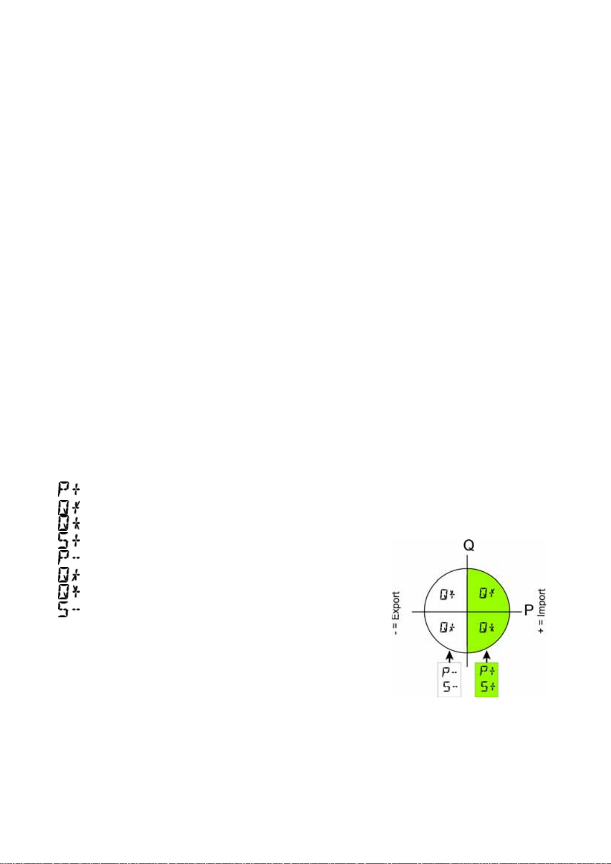
5.1.2.6.2 4-20 mA output configuration of the average AVG values
In Import-Export mode, the instrument can provide the measuring on the 4 dials, but the selection can be
made on a dial at a time.
In selection mode, the measures are visualized as follows:
Imported Active Power (import)
Inductive reactive Power with imported Active Power.
Capacitive reactive Power with imported Active Power
Apparent Power with imported Active Power
Exported Active Power (export)
Inductive reactive Power with exported Active Power
Capacitive reactive Power with exported Active Power
Apparent Power with exported Active Power
The quadrant selection is operated according to the following
trigonometric convention:
26
5.1.2.7 Clock calendar configuration (for X3M-D only)
The X3M-D is equipped with a clock/calendar with internal battery having a 15 years life time.
The clock/calendar supports the time zone handling functions and the automatic change from Standard Time
to Daylight Saving Time and vice versa.
The instrument is set by default to the Europe/Rome time and time zone.
The clock/calendar setting is covered by the last two SETUP pages.
Clock format
The following Time formats are foreseen:
Coordinated Universal Time (UTC): commonly known as GMT (Greenwich Mean Time): it is the
universal time, applicable to any place on earth.
Standard Time: it is the local time of a specific time zone, based on the sun cycles (known as Solar
Time
Daylight Saving Time it is the local time of a specific time zone when an offset on standard time is
applied (DST offset). The introduction of this offset allows to increase the availability of hours with
natural light in the summer evenings.
Wall time: it is how we refer to the clock time in each time zone. The Wall time actually coincides with
the Daylight Saving Time or the Standard Time depending whether an offset Solar time is
occurring or not.
The difference between Standard Time and UTC time is called GMT offset.
Summarizing:
GMT offset = UTC – Standard Time
Wall Time = Standard Time + DST offset = UTC + GMT offset + DST offset
The instrument RTC supports the following time information:
• UTC Date/time
• Time zone identification
Starting from the UTC time, the instrument automatically calculates the local time (Wall Time) of any place
on earth
The pertinent time zone is entered to the instrument by a numeric index (time zone index) either on the set
up procedure or on a MODBUS register.
NOTE:
The clock is updated by using the local time or “wall time” that the instrument converts in UTC, consequently,
if the time zone is wrong, the clock will be wrong too.
The instrument clock operates in UTC, therefore a correct time zone attribution is essential. Check
whether the time zone entry is correct before modifying the clock. Otherwise a wrong time setting
could be involuntarily programmed
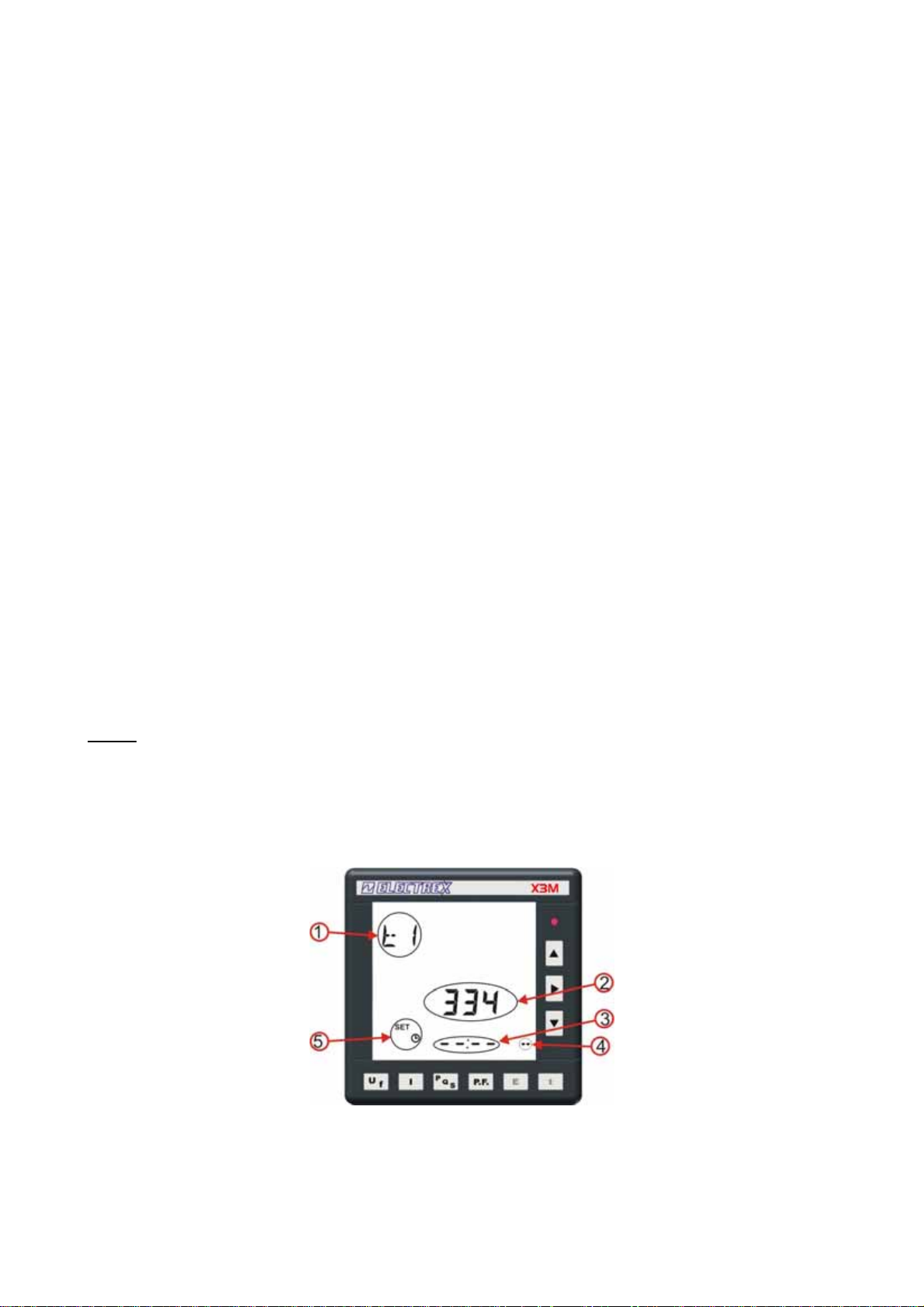
(1) It identifies the time programming page N° 1.
(2) Time zone 334 = Europe/Rome is valid all over central Europe. See the enclosed layout to identify
the right time zone
27

(3) Time Configuration in hours and minutes. Starting the selection the configuration is
Pushing the button
first the hours then the minutes. The hour change will occur only exiting the programming mode.
The hour change will influence the data storage thus it is important to operate modifications only if
strictly necessary, otherwise leave to the instrument management software the clock update.. If
you maintain the configuration
edited and clock changes be avoided, it is necessary to set the display to
located after the last valid hour or minute (i.e. beyond 11 pm or under 12 am).
(4) Identifies the standard time.
summer time.
(5) Identifies the clock set up page.
and it is possible to visualize the actual time and date and modify them,
the clock will not be modified. Should modifications be
which is
while identifies the daylight saving or
In the second page of clock set up it is possible to program the calendar.
(6) It identifies the time programming page N° 2.
(7) Area of calendar setting and starting from left: year, month, day
it is possible to avoid the modification saving, switching to the initial position
which does not save modifications.
. Even for the date
5.1.2.7.1 Clock set up with Modbus registers.
To set up the calendar clock the Modbus Holding Registers from 140 to 165 have to be used.
Refer to chapter 9 for the details.
28

5.1.2.7.2 Time zones
The pertinent time zone is entered to the instrument by a numeric index (time zone index).
The time zone index and the standard time zone names are shown in the charts below:
Standard Timezone Name (FW > 1.06)
Africa/Abidjan
Africa/Accra
Africa/Addis_Ababa
Africa/Algiers
Africa/Asmera
Africa/Bamako
Africa/Bangui
Africa/Banjul
Africa/Bissau
Africa/Blantyre
Africa/Brazzaville
Africa/Bujumbura
Africa/Cairo
Africa/Casablanca
Africa/Ceuta
Africa/Conakry
Africa/Dakar
Africa/Dar_es_Salaam
Africa/Djibouti
Africa/Douala
Africa/El_Aaiun
Africa/Freetown
Africa/Gaborone
Africa/Harare
Africa/Johannesburg
Africa/Kampala
Africa/Khartoum
Africa/Kigali
Africa/Kinshasa
Africa/Lagos
Africa/Libreville
Africa/Lome
Africa/Luanda
Africa/Lubumbashi
Africa/Lusaka
Africa/Malabo
Africa/Maputo
Africa/Maseru
Africa/Mbabane
Africa/Mogadishu
Africa/Monrovia
Africa/Nairobi
Africa/Ndjamena
Africa/Niamey
Africa/Nouakchott
Africa/Ouagadougou
Africa/Porto-Novo
Africa/Sao_Tome
Africa/Timbuktu
X3M-D
Timezone Index
0
1
2
3
4
5
6
7
8
9
10
11
12
13
14
15
16
17
18
19
20
21
22
23
24
25
26
27
28
29
30
31
32
33
34
35
36
37
38
39
40
41
42
43
44
45
46
47
48
Standard Timezone Name (FW > 1.06)
Africa/Tripoli
Africa/Tunis
Africa/Windhoek
America/Adak
America/Anchorage
America/Anguilla
America/Antigua
America/Araguaina
America/Argentina/Buenos_Aires
America/Argentina/Catamarca
America/Argentina/ComodRivadavia
America/Argentina/Cordoba
America/Argentina/Jujuy
America/Argentina/La_Rioja
America/Argentina/Mendoza
America/Argentina/Rio_Gallegos
America/Argentina/San_Juan
America/Argentina/Tucuman
America/Argentina/Ushuaia
America/Aruba
America/Asuncion
America/Bahia
America/Barbados
America/Belem
America/Belize
America/Boa_Vista
America/Bogota
America/Boise
America/Cambridge_Bay
America/Campo_Grande
America/Cancun
America/Caracas
America/Cayenne
America/Cayman
America/Chicago
America/Chihuahua
America/Costa_Rica
America/Cuiaba
America/Curacao
America/Danmarkshavn
America/Dawson
America/Dawson_Creek
America/Denver
America/Detroit
America/Dominica
America/Edmonton
America/Eirunepe
America/El_Salvador
America/Fortaleza
X3M-D
Timezone Index
49
50
51
52
53
54
55
56
66
71
400
76
109
401
121
402
403
404
405
57
58
59
60
61
62
63
64
65
67
68
69
70
72
73
74
75
77
78
79
80
81
82
83
84
85
86
87
88
89
29

Standard Timezone Name (FW > 1.06)
America/Glace_Bay
America/Godthab
America/Goose_Bay
America/Grand_Turk
America/Grenada
America/Guadeloupe
America/Guatemala
America/Guayaquil
America/Guyana
America/Halifax
America/Havana
America/Hermosillo
America/Indiana/Knox
America/Indiana/Marengo
America/Indiana/Vevay
America/Indianapolis
America/Inuvik
America/Iqaluit
America/Jamaica
America/Juneau
America/Kentucky/Monticello
America/La_Paz
America/Lima
America/Los_Angeles
America/Louisville
America/Maceio
America/Managua
America/Manaus
America/Martinique
America/Mazatlan
America/Menominee
America/Merida
America/Mexico_City
America/Miquelon
America/Monterrey
America/Montevideo
America/Montreal
America/Montserrat
America/Nassau
America/New_York
America/Nipigon
America/Nome
America/Noronha
America/North_Dakota/Center
America/Panama
America/Pangnirtung
America/Paramaribo
America/Phoenix
America/Port_of_Spain
America/Port-au-Prince
America/Porto_Velho
America/Puerto_Rico
America/Rainy_River
X3M-D
Timezone Index
90
91
92
93
94
95
96
97
98
99
100
101
102
103
104
105
106
107
108
110
111
112
113
114
115
116
117
118
119
120
122
123
124
125
126
127
128
129
130
131
132
133
134
135
136
137
138
139
141
140
142
143
144
Standard Timezone Name (FW > 1.06)
America/Rankin_Inlet
America/Recife
America/Regina
America/Rio_Branco
America/Santiago
America/Santo_Domingo
America/Sao_Paulo
America/Scoresbysund
America/St_Johns
America/St_Kitts
America/St_Lucia
America/St_Thomas
America/St_Vincent
America/Swift_Current
America/Tegucigalpa
America/Thule
America/Thunder_Bay
America/Tijuana
America/Toronto
America/Tortola
America/Vancouver
America/Whitehorse
America/Winnipeg
America/Yakutat
America/Yellowknife
Antarctica/Casey
Antarctica/Davis
Antarctica/DumontDUrville
Antarctica/Mawson
Antarctica/McMurdo
Antarctica/Palmer
Antarctica/Rothera
Antarctica/Syowa
Antarctica/Vostok
Asia/Aden
Asia/Almaty
Asia/Amman
Asia/Anadyr
Asia/Aqtau
Asia/Aqtobe
Asia/Ashgabat
Asia/Baghdad
Asia/Bahrain
Asia/Baku
Asia/Bangkok
Asia/Beirut
Asia/Bishkek
Asia/Brunei
Asia/Calcutta
Asia/Choibalsan
Asia/Chongqing
Asia/Colombo
Asia/Damascus
X3M-D
Timezone Index
145
146
147
148
149
150
151
152
153
154
155
156
157
158
159
160
161
162
163
164
165
166
167
168
169
170
171
172
173
174
175
176
177
178
179
180
181
182
183
184
185
186
187
188
189
190
191
192
193
194
195
196
197
30
 Loading...