

Elecraft KXPA100 Users Manual
E
LECRAFT
KXPA100
100-W
O
Copyright © 2013, Elecraft, Inc.
ATT AMPLIFIER
WNER’S MANUAL
Draft, June 3, 2013
All Rights Reserved

Contents
Key to Symbols and Text Styles ............................................................................................................... 3
Installation ................................................................................................................................................ 4
Operation .................................................................................................................................................. 6
Power On ..................................................................................................................................................... 6
Band Switching ............................................................................................................................................ 7
Transmitting ................................................................................................................................................. 7
Monitoring ................................................................................................................................................... 8
Fault Conditions ........................................................................................................................................... 8
Firmware Updates ..................................................................................................................................... 9
Specifications .......................................................................................................................................... 10
Customer Service and Support ............................................................................................................... 11
Theory of Operation ............................................................................................................................... 12
2

Key to Symbols Abbreviations and Text Styles
Important – read carefully
Operating tip
TEMP
PK HOLD
LED
Tap switch function (labeled above a switch)
Hold switch function (labeled below a switch; hold for 1/2 sec. to activate)
Light Emitting Diode
3
Installation
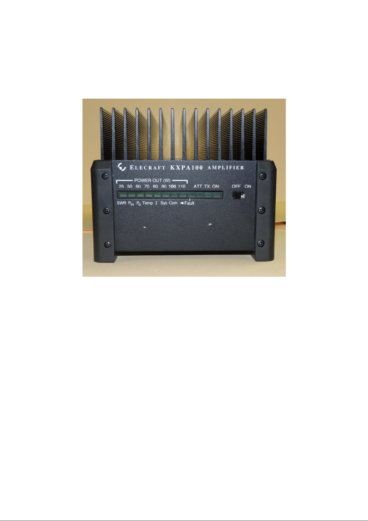
The KXPA100 is designed for installation in either a home station or mobile environment.
Two important mounting criteria must be observed. The heat sink fins must be oriented vertically to optimize
natural convection air currents and the power cable run must be as direct as possible.
There are three recommended mounting positions: base down flat, with the heat sink horizontal and fins
pointing up; front panel down, with the fins vertical; and rear panel down with the heat sink fins vertical. Do not
place other equipment, papers, etc., on top of the KXPA100. Keep the KXPA100 out of direct sunlight if
possible.
The KXPA100 draws as much as 24 A of power supply current. The power cable should be as short and direct
as possible to minimize voltage drop. The red power lead connects to positive (+) 13.8V and the black lead
connects to the negative terminal. The negative terminal is common to chassis ground. If the supplied cable is
not long enough, make a cable using no smaller than #10 AWG conductors. For mobile installations, connect the
power cable directly to the battery terminals.
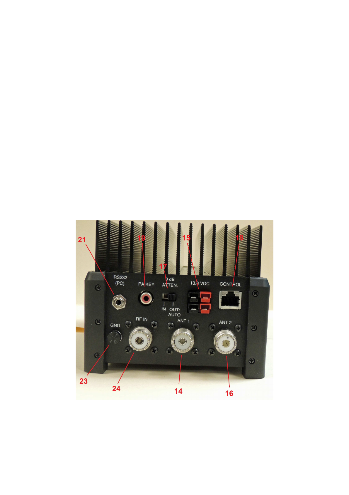
The following text uses braces to refer to numbered elements in the front- and rear-panel illustrations below. For
example, {14} refers to 14, the
RF OUTPUT
connector.
Figure 1. KXPA100 Rear Panel
4
 Loading...