

Page 1

ESIM4
ESIM4 Q
Battery Powered GSM Auto Dialler/
Mini Alarm System
Page 2

User Manual v1.5
Valid for ESIM4 v03.01.04 and up.
SAFETY INSTRUCTIONS
Please read and follow these safety guidelines in order to maintain safety of operators and people around:
• Battery powered GSM auto dialler/mini alarm system ESIM4/ESIM4 Q (later referenced as “the system”, “the device” or “ESIM4”) is
equipped with a radio trans ceiver operating in GSM900/1800 bands / GSM850/900/1800/1900 bands respectively.
• DO NOT use the system where it can cause potential danger and interfere with other devices – such as medical devices.
• DO NOT use the system in hazardous environment.
• DO NOT expose the system to high humidity, chemical environment or mechanical impact.
• DO NOT attempt to repair the system yourself – any repairs must be carried out by fully qualied personnel only.
ESIM4 is a device that must be installed in limited access areas. Any system repairs must be done only by qualied, safety
aware personnel.
Remove all batteries before installing. Never install or carry out maintenance during stormy weather.
The system must be powered by four 1,5 V lithium AA type batteries only. When inserting the batteries into the battery slots,
mind the polarity terminals! Any additional device you connect to the system, such as a computer, must be powered by an EN
60950-1 approved supply.
To switch the system o, remove all four 1,5 V lithium AA type batteries.
Fuse F1 model – miniSMDC 0,5A. Replacement fuses have to be exactly the same as indicated by the manufacturer.
If you use a computer for the device conguration, it must be earthed.
The WEEE (Waste Electrical and Electronic Equipment) symbol on this product (see left) means it must not be disposed of in
household waste. To prevent possible harm to human health and/or the environment, you must dispose of this product in an
approved and environmentally safe recycling facility. For further information contact your system supplier, or your local waste
authority.
2
2 EN
ESIM4 Manual v1.5
Page 3

CONTENTS
1. GENERAL INFORMATION ...........................................................................................................................................................6
2. TECHNICAL SPECIFICATIONS ....................................................................................................................................................6
2.1. Electrical and Mechanical Characteristics .....................................................................................................................................................6
2.2. Main Unit and LED and Connector Functionality .........................................................................................................................................7
2.3. Wiring Diagrams ................................................................................................................................................................................................8
3. INSTALLATION ...........................................................................................................................................................................9
4. GENERAL OPERATIONAL DESCRIPTION..................................................................................................................................10
5. CONFIGURATION METHODS ....................................................................................................................................................10
5.1. SMS Text Messages .........................................................................................................................................................................................10
5.2. ELDES Conguration Tool ..............................................................................................................................................................................10
5.3. QR Codes ...........................................................................................................................................................................................................11
6. SMS PASSWORD .......................................................................................................................................................................11
7. USER PHONE NUMBERS ..........................................................................................................................................................12
8. DATE AND TIME........................................................................................................................................................................13
8.1. Automatic Date and Time Synchronization ................................................................................................................................................13
9. SLEEP AND WAKE-UP MODES .................................................................................................................................................14
9.1. Wake-Up Scheduler ........................................................................................................................................................................................15
10. INPUTS ....................................................................................................................................................................................16
10.1. Input Z1 ..........................................................................................................................................................................................................16
10.1.1. Digital Mode ...................................................................................................................................................................................................17
10.1.2. Analog Mode ..................................................................................................................................................................................................18
10.1.3. AUX Output ....................................................................................................................................................................................................18
10.2. Input Z2 ..........................................................................................................................................................................................................19
10.2.1. Digital Mode .................................................................................................................................................................................................. 20
10.2.2. Temperature Sensor Mode .........................................................................................................................................................................21
10.2.3. iButton Key Mode .........................................................................................................................................................................................23
10.3. Alarm/Restore Notications ...................................................................................................................................................................... 24
10.3.1. Alarm Delay ................................................................................................................................................................................................... 26
11. SHOCK SENSOR .......................................................................................................................................................................27
12. ALARM/RESTORE NOTIFICATION SCHEDULER ..................................................................................................................... 28
13. OUTPUT ................................................................................................................................................................................. 29
13.1. Output Name ................................................................................................................................................................................................... 29
13.2. Turning Output ON and OFF ......................................................................................................................................................................... 29
14. BATTERY LEVEL MONITORING ...............................................................................................................................................32
15. ARMING AND DISARMING .......................................................................................................................................................33
16. SYSTEM INFORMATION. STATUS SMS ................................................................................................................................... 34
16.1. Periodic Status SMS .......................................................................................................................................................................................34
17. SYSTEM NOTIFICATIONS ........................................................................................................................................................35
18. EVENT MEMORY .....................................................................................................................................................................37
19. REMOTE LISTENING ............................................................................................................................................................... 38
20. TECHNICAL SUPPORT ........................................................................................................................................................... 39
20.1. Troubleshooting ............................................................................................................................................................................................. 39
20.2. Restoring Default Parameters ..................................................................................................................................................................... 39
20.3. Updating the Firmware via USB Cable ........................................................................................................................................................ 39
21. RELATED PRODUCTS .............................................................................................................................................................40
ESIM4 Manual v1.5
3
3EN
Page 4

Limited Liability
The buyer agrees that the system will reduce the risk of re, theft, burglary or other danger but that it does not guarantee against the occurrence of such events. “ELDES UAB” will not take any responsibility for the loss of personal eects, property or revenue whilst using the
system. The liability of “ELDES UAB” is limited to the value of the system purchased. “ELDES UAB” is not aliated with any mobile/wireless/
cellular provider and is therefore not responsible for the quality of such services.
Manufacturer Warranty
The system carries a 24-month manufacturer warranty from “ELDES UAB”. The warranty begins the day the system is purchased by the
user and the receipt must be retained as proof of purchase date. The warranty remains valid only if the system is used as intended, following all guidelines outlined in this manual and in accordance with the operating conditions specied. The warranty is void if the system
has been exposed to mechanical impact, chemicals, high humidity, uids, corrosive and hazardous environments or force majeure factors.
Dear Customer,
Thank you for choosing to purchase the battery powered GSM dialler ESIM4. Your thoughtful decision will ensure reliable solution for
many years as all ELDES products are manufactured to meet the highest standards.
We are condent that you will be completely satised with your product. However, in the unlikely event that you do experience a
problem, please contact the dealer from whom you made your purchase.
UAB ELDES
www.eldes.lt
Contents of Pack
Item Quantity
ESIM4 ...........................................................1
User manual. ...............................................1
1,5 V Lithium AA batteries........................4
GSM antenna... ............................................1
Plastic gland.... ............................................1
Screws. ........................................................2
Terminal block... .........................................1
Not included:
• SIM card – we recommend you get a contract SIM, not Pay As You Go.
• miniUSB cable - can be obtained from your local distributor.
• Temperature sensor - can be obtained from your local distributor.
• Microphone - can be obtained from your local distributor
• iButton key reader- can be obtained from your local distributor
• iButton keys - can be obtained from your local distributor
• Buzzer - can be obtained from your local distributor
4
4 EN
ESIM4 Manual v1.5
Page 5

Copyright © “ELDES UAB”, 2015. All rights reserved
It is strictly forbidden to copy and distribute information in this document or pass to a third party without an
advanced written authorization from “ELDES UAB”. “ELDES UAB” reserves the right to update or modify this
document and/or related products without a warning. Hereby, “ELDES UAB” declares that the battery powered GSM auto dialler/mini alarm system ESIM4 is in compliance with the essential requirements and other
relevant provisions of Directive 1999/5/EC. The declaration of conformity may be consulted at www.eldes.lt.
ESIM4 Manual v1.5
5
5EN
Page 6

1. GENERAL INFORMATION
OUT
ESIM4 is a micro-controller based device used to inform users about the alarm in automatic or security systems, supply power to an auxiliary
device and control one electrical appliance or measure temperature. The device can also be used as a mini-alarm system.
Examples of using the system:
• Suitable in areas without a 230V power supply.
• Switching one electronic device ON/OFF.
• Notication of failure or restoration of an electronic device via SMS text message and/or phone call.
• Property security.
• Temperature monitoring.
• Lighting, garden watering, water pump and other electrical equipment control via SMS text messages.
• Remote listening to what is happening in the secured area.
Main features:
• Conguration by SMS text message and PC.
• Sleep mode for battery power saving for up to 2 years.
• Up to 10 users for system conguration, control and acceptance of system event notications by SMS text messages and phone calls.
• 2 inputs on board turning to 4 inputs when ATZ mode enabled.
• Inputs Z1-Z4 customizable to NC or NO.
• Input Z1/Z3 modes: digital or analog.
• 1 AUX output operating in accordance with the set up period.
• Input Z2/Z4 modes: digital, temperature sensor or iButton key.
• Mini-alarm system: arming/disarming by iButton key.
• Up to 8 temperature sensors support for temperature monitoring in dierent areas.
• 1 open-collector output for electrical appliance control.
• Built-in shock sensor for alarm/restore notication by SMS text message on vibration detection.
• Scheduled system operation in Wake-Up mode and on system event.
• Scheduled input alarm/restore notications.
• Periodic self-test notication by SMS text message to user phone number.
• Customizable notication texts.
• QR code generator allowing to arrange a single or multiple text commands in a single SMS text message and encrypt it in a QR code.
2. TECHNICAL SPECIFICATIONS
2.1. Electrical and Mechanical Characteristics
Battery type ............................................................................................1.5 V Lithium AA type batteries
Number of batteries ..............................................................................4
Current used in Sleep mode .................................................................30µAmax
GSM modem frequency .........................................................................ESIM4 - 900/1800 Mhz; ESIM4 Q - 850/900/1800/1900 MHz
Number of inputs ...................................................................................2
Digital input value range ......................................................................0... 3000mV
Analog input value range .....................................................................0... 24mA
Impulse duration ....................................................................................>600ms
Number of auxiliary terminals .............................................................1
Auxiliary output values .........................................................................12V 200mA max
Maximum supported number of temperature sensors ...................8
Number of outputs ................................................................................1
Output circuit ..........................................................................................Open collector output.
Output current........................................................................................200mA max
Supported temperature sensor model ..............................................Maxim®/Dallas® DS18S20, DS18B20
Supported iButton key model .............................................................. Maxim®/Dallas® DS1990A
Dimensions .............................................................................................115x90x56mm (4.53x3.54x2.20in)
Enclosure rating .....................................................................................IP 65
Operating temperature range .............................................................-20…+50°C (-30...+55°C with limitations (-4... +122°F (-22... +131°F with
Humidity ..................................................................................................0-90% RH @ 0...+40°C (0-90% RH @ +32...+104°F) (non-condensing)
Output is pulled to COM
when enabled.
limitations))
ATTENTON: All 4 batteries must be of the same manufacturer.
6
6 EN
1 R
ESIM4 Manual v1.5
Page 7
NOTE: We recommend using Camelion P7 lithium 1.5V AA type and Energizer Ultimate lithium 1.5V AA type batteries or other ‘‘ELDES UAB’’
recommended batteries.
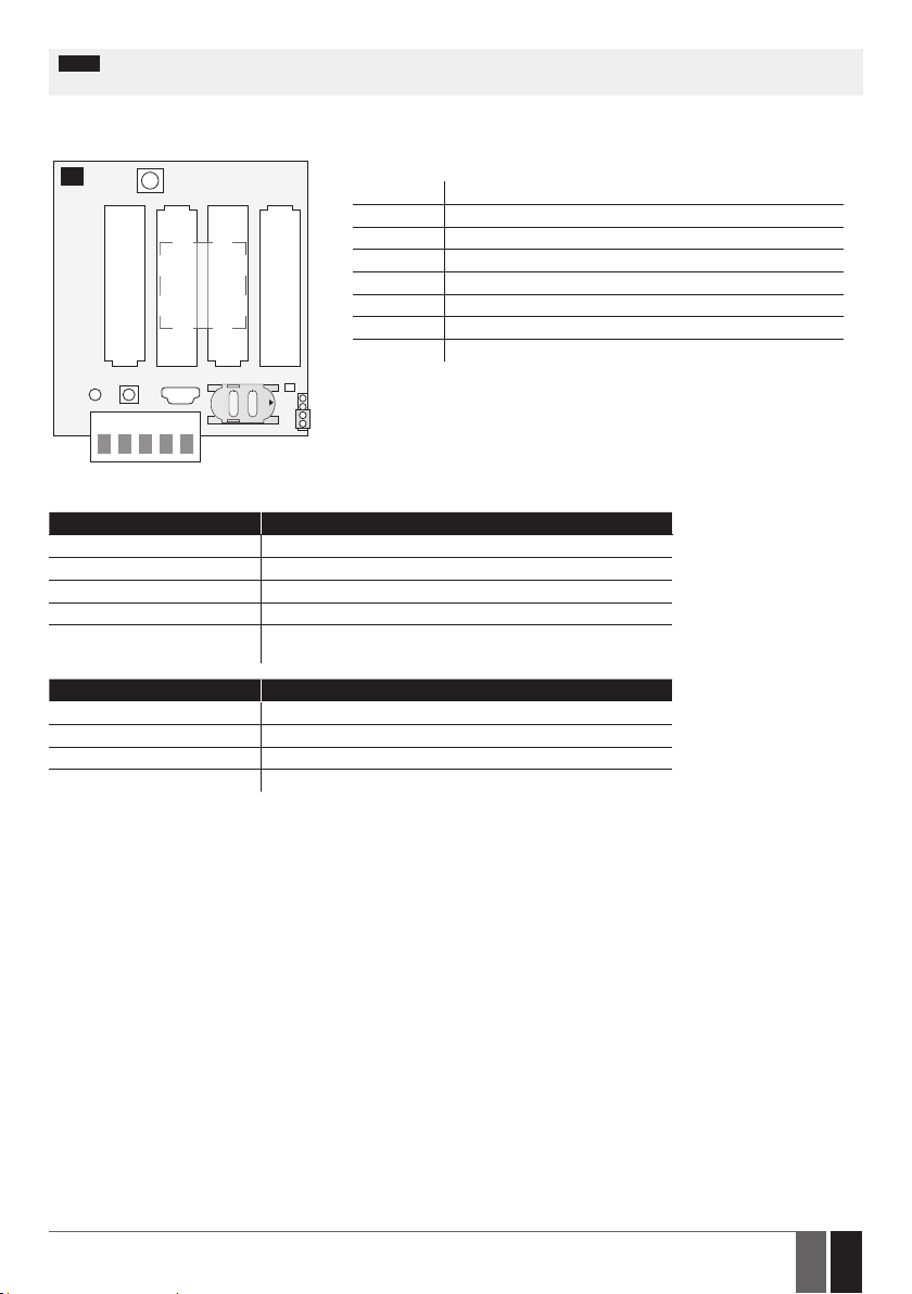
2.2. Main Unit and LED and Connector Functionality
1
ANT
- -
+
+
Main Unit Functionality
GSM MODEM GSM network 900/1800 MHz modem
SIM SIM card slot
LED Light-emitting diode indicator
BATTERY
GSM
MODEM
BATTERY
BATTERY
ANT GSM antenna
MIC Microphone
USB Mini USB port
DEF Button for restoring default settings
FW Pins for rmware upgrade
FW
LED
+ +
C1 Z2 Z1AUX COM
- -
SIM
USB
MICDEF
OPEN
Connectors Description
Z1 Digital input / analog input terminal
Z2 Digital input / temperature sensor or iButton data terminal (DATA)
COM Common terminal
AUX Auxiliary power supply terminal
C1 Open-collector output / temperature sensor or buzzer power
supply positive terminal (+4V)
LED indications Description
1 ash every 0.5 sec. SIM card is not present / PIN code enabled
3 quick ashes every 3 sec. Searching for GSM network
1 ash every 5 sec Connected to GSM network / system operating successfully
1 quick weak ash every 10 sec. The device is operating in Sleep mode
ESIM4 Manual v1.5
7
7EN
Page 8
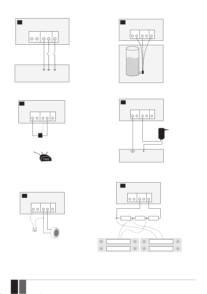
2.3. Wiring Diagrams
ESIM4
AUXC1 COM Z2 Z1
5,6KΩ
1KΩ2KΩ
2 3
ESIM4
AUXC1 COM
Z2 Z1
PGM2
PGM1
Alarm system or other appliance
General wiring AUX wiring
4
ESIM4
AUXC1 COM Z2 Z1
GND
DATA
DATA
+4V
+4V
DS18S20, DS18B20
Temperature sensor
GND
ESIM4
AUX
C1 COMZ2 Z1
20mA
PRESSURE
VESSEL
PRESSURE
4mA
SENSOR
Gauge pressure transmitter
5
ESIM4
AUX
C1 COMZ2 Z1
+
Electrical appliance
Power
supply
Temperature sensor wiring
6
ESIM4
AUXC1 COM Z2 Z1
+ -
BUZZER
brown
white
iButton
key reader
iButton key reader and buzzer wiring
8
8 EN
Output wiring
7
ESIM4
AUXC1 COMZ2 Z1
5,6KΩ
Z1
COM
Magnet
Example of input wiring in ATZ mode
1KΩ2KΩ
Z3
COM
Magnet
ESIM4 Manual v1.5
Page 9

3. INSTALLATION
For the connection of input/output terminals, use 0.50 mm2(0.02in2 ) 1 thread unshielded cable of up to 100m (328.08ft) length.
1. Wire up the system in accordance with the wiring diagrams (see 2.3 Wiring Diagrams for more details).
2. If necessary to run the wires, drill out a hole of 13mm (0.51in) diameter in the ESIM4 enclosure and insert the plastic gland supplied in
ESIM4 package. The plastic gland must be facing down.
8
3. The system comes with a GSM antenna that is already connected. If another type of GSM antenna is required, please replace the
standard GSM antenna with an antenna of your choice.
4. When placing the system, follow the recommendations:
11
5. Disable the PIN code request of the SIM card by inserting it into a mobile phone and following the proper menu steps.
6. Once the PIN code is disabled, insert the SIM card into the SIM card slot / holder of ESIM4 system.
12
9
Never install in the following locations:
• inside the metal cabinet
• closer than 20cm (7.87in) from the
metal surface and/or power lines
13
10
14
15
OPEN
16
OPEN
7. Insert all 4 batteries and wait until the LED indicator starts blinking indicating successful micro-controller operation. The system is
now running in Wake-Up mode for 3 minutes to congure the system by SMS text messages (see 5. CONFIGURATION METHODS).
8. Change the default SMS password (see 6. SMS PASSWORD for more details).
9. Set the phone number for User 1 (see 7. USER PHONE NUMBERS for more details).
10. Once the LED indicator lights OFF, the system will switch to Sleep mode and it will no longer accept any SMS text messages.
ATTENTION: The system is NOT compatible with pure 3G SIM cards. Only 2G/GSM SIM cards and 3G SIM cards with 2G/GSM prole enabled
are supported. For more details, please contact your GSM operator.
ATTENTION: We also recommend you to disable call forwarding, voice mail/text message reports on missed/busy calls and similar services
that might cause incorrect system operation. Please contact your GSM operator for more details on these services and how to disable them.
9
ESIM4 Manual v1.5
9EN
Page 10

NOTE: For maximum system reliability we recommend you do NOT use a Pay As You Go SIM card. Otherwise, in the event of insucient credit
balance on the SIM card, the system would fail to make a phone call or send SMS text messages.
NOTE: We advise you to choose the same GSM SIM provider for your system as for your mobile phone. This will ensure the fastest, most
reliable SMS text message delivery service and phone call connection.
NOTE: Even though the installation process of ESIM4 is not too complicated, we still recommend to perform it by a person with basic knowl-
edge in electrical engineering and electronics to avoid any system damage.
4. GENERAL OPERATIONAL DESCRIPTION
The battery powered GSM dialler ESIM4 uses the GSM network for event transmission by SMS text message and/or phone call to the listed
user phone numbers. In addition to being informed about alarm and restore events of the inputs, the users can use the system to supply
power to an auxiliary device and control one electrical appliance using an output or measure the temperature using up to 8 temperature
sensors.
The system has two inputs (normally closed or normally open) for a detection device connection. By enabling the ATZ mode and connecting
the resistors, 2 detection devices can be connected to each input. The system also supplies 12 volt power to an auxiliary device, such as,
pressure sensor. In addition, the system comes equipped with a built-in shock sensor for any vibration detection where the system is placed.
ESIM4 can also be used as a mini alarm system supporting arming/disarming feature by iButton key.
ESIM4 can control 1 electrical appliance on receipt of the correct SMS text message or via ELDES Conguration Tool software. For example,
users can turn on or o the heating, lighting, lift the gates, blinds etc.
By default, when an authorised number calls to the system, the device answers and the user can listen for 60 seconds to what is going on in
the premises. This function works only when a microphone is connected. The system will ignore SMS requests and voice calls coming from
unknown phone numbers.
Most of the time the system operates in Sleep mode allowing to save battery power for up to 2 years. However, when an event occurs,
requiring the device to send SMS messages and/or dial one of the listed user phone numbers, the device will switch to Wake-Up mode.
5. CONFIGURATION METHODS
5.1. SMS Text Messages
!!! In this user manual the underscore character ”_” represents one space character. Every underscore character must be
replaced by a single space character. There must be no spaces or other unnecessary characters at the beginning and at the
end of the SMS text message.
In order to congure and control the system by SMS text message, send the text command to the ESIM4 system phone number from one of the listed user phone numbers. The system supports multiple text commands arranged in a single SMS text
SMS
message. The structure of SMS text message consists of 4-digit SMS password (the default SMS password is 0000 – four
zeros), the parameter and value. For some parameters the value does not apply e. g. STATUS. The variables are indicated in
lower-case letters, while a valid parameter value range is indicated in brackets.
For more details on how to encrypt an SMS text message in a QR code, please refer to 5.3. QR Codes and ELDES Conguration Tool
software’s HELP section.
5.2. ELDES Conguration Tool
Cong
10
10 EN
Software ELDES Conguration Tool is intended for ESIM4 battery powered GSM dialler conguration via USB port locally. This
software simplies system conguration process by allowing to use a personal computer in the process. Before starting to use
Tool
ELDES Conguration Tool software, please read the user guide provided in the software’s HELP section.
ELDES Conguration Tool is freeware and can be downloaded at: www.eldes.lt/download
NOTE: Conguration by USB cable and ELDES Conguration Tool software does not require the batteries to be inserted in the device.
ESIM4 Manual v1.5
Page 11
5.3. QR Codes
For user convenience, ELDES Conguration Tool software comes equipped with QR code generator allowing to arrange a single or multiple
text commands in a single SMS text message and encrypt it in a QR code. Once the QR code is generated, the user using his mobile phone’s
built-in camera can take a picture of the code right from his monitor’s screen, then decrypt it to the SMS text message using his mobile
phone’s application and send the SMS text message to the system.
Cong
Generate QR code
This operation may be carried out from the PC using the ELDES Conguration Tool software.
Tool
6. SMS PASSWORD
For security reasons, the system uses the following type of password:
SMS password – 4-digit password used for system conguration and control from user phone number by SMS text message . By default,
SMS password is 0000, which MUST be changed!
SMS text message content:
wwww_PSW:ssss
Set SMS password
SMS
Value: wwww – 4-digit default SMS password; ssss – 4-digit new SMS password; range –
[0001... 9999].
Example: 0000_PSW:1111
Cong
This operation may be carried out from the PC using the ELDES Conguration Tool software.
Tool
ESIM4 Manual v1.5
11
11EN
Page 12

7. USER PHONE NUMBERS
The system supports up to 10 user phone numbers identied as User 1 through 10. When the phone number is set, the user will be able to
congure the system by SMS text messages as well as to receive the alarm/restore phone calls and SMS text messages from the system
(see 10.3. Alarm/Restore Notications).
By default, the system accepts incoming calls and SMS text messages from any phone number. Once a user phone number is listed, the
system ignores any incoming calls and SMS text messages from a non-listed phone number as well as it rejects the SMS text messages
containing wrong SMS password even from a listed user phone number.
To set User 1 phone number is mandatory, while the other 9 are optional. The supported phone number formats are the following:
• International (with plus) – The phone numbers must be entered starting with plus and an international country code in the following
format: +[international code][area code][local number], example for UK: +44170911XXXX1.
• International (with 00) – The phone numbers must be entered starting with 00 and an international country code in the following
format: 00[international code][area code][local number], example for UK: 0044170911XXXX1.
• Local – The phone numbers must be entered starting with an area code in the following format: [area code][local number], example
for UK: 0170911XXXX1.
SMS text message content:
Set user phone
number
ssss_NRup:ttteeellnnuumm
SMS
Value: ssss – 4-digit SMS password; up – user phone number slot, range – [1... 10]; ttteeelln-
nuumm – up to 15 digits user phone number.
Example: 1111_NR1:+44170911XXXX1
Cong
This operation may be carried out from the PC using the ELDES Conguration Tool software.
Tool
View user phone
numbers
Delete user phone
number
ATTENTION: NEVER add a phone number of the device’s SIM card as a user phone number!
ATTENTION: Once User 1 phone number is set, it will be restricted to modify it only.
NOTE: Multiple user phone numbers can be set by a single SMS text message, e.g.: 1111_NR1:+4417091111111_ NR2:+4417091111112_
NR6:017091111113_NR10:+4417091111114
Cong
This operation may be carried out from the PC using the ELDES Conguration Tool software.
Tool
SMS text message content:
ssss_NRup:
SMS
Value: ssss – 4-digit SMS password; up – user phone number slot, range – [1... 10].
Example: 1111_NR4:
Cong
This operation may be carried out from the PC using the ELDES Conguration Tool software.
Tool
12
12 EN
ESIM4 Manual v1.5
Page 13

8. DATE AND TIME
The system comes equipped with internal real-time clock (RTC) that keeps track of the current date and time. Once the system is up and
running, the user must set the correct date and time, otherwise the system will not operate properly. After shutting down and starting up
the system, the date and time must be set again.
SMS text message content:
ssss_CLK:yyyy.mm.dd_hr:mn
Set date and time
View date and time
For more details on how to view system’s information that may include date and time, please refer to 16. SYSTEM INFORMATION.
STATUS SMS.
8.1. Automatic Date and Time Synchronization
This feature enables the system to set the date and time automatically without the user being involved in this process. The system
supports the following method of automatic date and time synchronization that is used whenever the system switches to Wake-Up mode:
• Via GSM network – Once enabled, the system automatically sends a date/time request to the GSM operator. This method is the most
accurate synchronization method. Some GSM operators might not support it.
By default, synchronization via GSM network is disabled. To enable/disable automatic date and time synchronization via GSM network,
please refer to the following conguration methods.
Enable automatic
date and time
synchronization
SMS
Value: ssss – 4-digit SMS password; yyyy – year; mm – month, range – [01... 12]; dd – day,
range – [01... 31]; hr – hours, range – [00... 23]; mn – minutes, range – [00... 59].
Example: 1111_CLK:2013.03.16_14:33
Cong
This operation may be carried out from the PC using the ELDES Conguration Tool software.
Tool
SMS text message content:
ssss_STATUS
SMS
Value: ssss – 4-digit SMS password.
Example: 1111_STATUS
Cong
This operation may be carried out from the PC using the ELDES Conguration Tool software.
Tool
SMS text message content:
ssss_MTIME:ON
SMS
Value: ssss – 4-digit SMS password;
Example: 1111_MTIME:ON
Disable automatic
date and time
synchronization
ESIM4 Manual v1.5
Cong
This operation may be carried out from the PC using the ELDES Conguration Tool software.
Tool
SMS text message content:
ssss_MTIME:OFF
SMS
Value: ssss – 4-digit SMS password;
Example: 1111_MTIME:OFF
Cong
This operation may be carried out from the PC using the ELDES Conguration Tool software.
Tool
13
13EN
Page 14

9. SLEEP AND WAKE-UP MODES
The system can operate in one of the following modes at a time:
• Wake-Up – The micro-controller and the GSM modem are active and the system is ready to send and accept the SMS text messages and
phone calls to/from the listed user phone number.
• Sleep – The micro-controller and the GSM modem are disabled and the system will not be able to accept the SMS text messages or
phone calls from the listed user phone number. Normally, this mode is used most of the system’s uptime to signicantly extend battery
life.
The system starts up in Wake-Up mode and operates in this mode for 3 minutes. When the 3-minute period expires, the system will switch
to Sleep mode and operate in this mode until an event occurs or Wake-Up scheduler comes into eect (see 9.1. Wake-Up Scheduler).
When an event occurs, the system will follow this pattern:
1) Switches to Wake-Up mode.
2) Noties the user by SMS text message and/or phone call.
3) Stays in Wake-Up mode for 10 seconds.
4) Returns to Sleep mode.
By default, after notifying the user on a certain event, the system will stay in Wake-Up mode for 10 second time period. To set a dierent
time period, please refer to the following conguration methods.
Set time period to
stay in Wake-Up mode
after notifying the
user
View Wake-Up mode
parameters
ATTENTION: All 4 batteries must be inserted in the device for the system to run in Wake-Up mode. If the system is connect to the PC only via
USB cable, it will NEVER switch to Wake-Up mode.
NOTE: 0 value makes the system to instantly return to Sleep mode after notifying the user.
For more details on the system events and the algorithm of how the system sends the notications, please refer to 17. SYSTEM
NOTIFICATIONS.
SMS text message content:
SMS
ssss_MONT:se
Value: ssss – 4-digit SMS password; se – seconds, range – [0... 65535].
Example: 1111_MONT:25
Cong
This operation may be carried out from the PC using the ELDES Conguration Tool software.
Tool
Cong
This operation may be carried out from the PC using the ELDES Conguration Tool software.
Tool
14
14 EN
ESIM4 Manual v1.5
Page 15
9.1. Wake-Up Scheduler
The system comes equipped with 5 schedulers that allow to set up the periods of time in day for the system to operate in Wake-Up mode.
Typically, this feature is used for device conguration via SMS text messages and/or receiving system status on request.
Each scheduler includes the following parameters:
• Status – Determines whether the scheduler will apply or not.
• Start: Hour | Minutes – Determines the point in time when the system switches to Wake-Up mode.
• End: Hour | Minutes – Determines the point in time when the system switches back to Sleep mode.
By default, all schedulers are disabled and unset. To enable/disable and set up the schedulers, please refer to the following conguration
methods.
SMS text message content:
Enable and set up
scheduler
Disable scheduler
ssss_ERTc:hr:mn_ hr:mn
SMS
Value: ssss – 4-digit SMS password; c – scheduler number, range – [1... 5]; hr – hours, range –
[00... 23]; mn – minutes, range – [00... 59].
Example: 1111_ERT4:15:02_19:00
Cong
This operation may be carried out from the PC using the ELDES Conguration Tool software.
Tool
SMS text message content:
ssss_ERTc:OFF
SMS
Value: ssss – -digit SMS password; c – scheduler number, range – [1... 5].
Example: 1111_ERT4:OFF
Cong
This operation may be carried out from the PC using the ELDES Conguration Tool software.
Tool
View scheduler
parameters
ESIM4 Manual v1.5
Cong
This operation may be carried out from the PC using the ELDES Conguration Tool software.
Tool
15
15EN
Page 16
10. INPUTS
The system comes equipped with 2 inputs identied as Z1 and Z2. Depending on the selected input mode, the inputs are designed for
dierent detection device connection, such as pressure sensors, door contacts, temperature sensors etc. (see 10.1. Input Z1 and 10.2.
Input Z2). Once the detection device is triggered, the system will switch to Wake-Up mode and send a notication to the user phone
number (see 10.3. Alarm/Restore Notications).
The ATZ (Advanced Technology Zone) mode is a software-based feature that doubles the number of inputs and enables two detection
devices to be installed per 1 input terminal. Once this mode is enabled, it will result in additional input, identied as input Z3 (on input
terminal Z1) and input Z4 (on input terminal Z2), appearance. The ATZ mode is supported by Digital input mode only. The detection devices
must be wired to the input terminals as provided in 2.3. Wiring Diagrams.
SMS SMS text message content:
Enable ATZ mode for
input Z1 and input Z2
Disable ATZ mode for
input Z1 and input Z2
10.1. Input Z1
Input Z1 can operate in one of the following modes at a time:
• Digital – The system monitors the input voltage resulting in the input state change. Normally, this mode is used for door contacts and
other passive or active digital level sensors. This mode is set by default and it is compatible with ATZ mode. For more details on how to
manage the Digital mode, please refer to 10.1.1. Digital Mode.
• Analog – The system monitors the input current ranging resulting in the input state change. Typically, this mode is used for water-
level sensors, pressure sensors and other analog level sensors. For more details on how to manage the Analog mode, please refer to
10.1.2. Analog Mode.
ssss_ATZ:1;1
SMS
Value: ssss – 4digit SMS password.
Example: 1111_ATZ:1;1;
Cong Tool This operation may be carried out from the PC using the ELDES Conguration
Cong
Tool software.
Tool
SMS SMS text message content:
ssss_ATZ:0;0
SMS
Value: ssss – 4digit SMS password.
Example: 1111_ATZ:0;0;
Cong Tool This operation may be carried out from the PC using the ELDES Conguration
Cong
Tool software.
Tool
When active detection device is used, AUX output is required to power up the detection device. For more details, please refer to 10.1.3
AUX Output.
SMS text message content:
Set input mode as
Analog
Set input mode as
Digital
View input mode
parameters
16
16 EN
ssss_Z1:AN
SMS
Value: ssss – 4-digit SMS password.
Example: 1111_Z1:AN
Cong
This operation may be carried out from the PC using the ELDES Conguration Tool software.
Tool
SMS text message content:
ssss_Z1:DIG
SMS
Value: ssss – 4digit SMS password.
Example: 1111_Z1:DIG
Cong
This operation may be carried out from the PC using the ELDES Conguration Tool software.
Tool
Cong
This operation may be carried out from the PC using the ELDES Conguration Tool software.
Tool
ESIM4 Manual v1.5
Page 17
10.1.1. Digital Mode
When Digital mode is set, the system follows this pattern:
1) Monitors input voltage ranging from 0 mV through 3000 mV every 1 second.
2) Veries if the set up threshold (by default – 1500 mV) is not exceeded.
3) By default, the input is set as NO (normally open), therefore if the voltage drops below the threshold, it will result in input state change
to alarm followed by notifying the user by SMS text message and/or phone call.
4) When the voltage rises above the threshold, it will result in input state change to restore followed by notifying the user by SMS text
message and/or phone call.
SMS text message content:
Set threshold for
input Z1
Set input as NC
(normally closed)
Set input as NO
(normally open)
ssss_Z1VLEV:vthr
SMS
Value: ssss – 4-digit SMS password; vthr – threshold, range - [0... 3000] mV
Example: 1111_Z1VLEV:2350
Cong
This operation may be carried out from the PC using the ELDES Conguration Tool software.
Tool
SMS text message content:
ssss_Zi:NC
SMS
Value: ssss – 4-digit SMS password; i – input number, range – [1, 3].
Example: 1111_Z1:NC
Cong
This operation may be carried out from the PC using the ELDES Conguration Tool software.
Tool
SMS text message content:
ssss_Zi:NO
SMS
Value: ssss – 4-digit SMS password; i – input number, range – [1, 3].
Example: 1111_Z3:NO
Cong
This operation may be carried out from the PC using the ELDES Conguration Tool software.
Tool
SMS text message content:
ssss_STATUS
View input state
View real-time input
voltage
View Digital mode
parameters
NOTE: If AUX output is used along with Digital input mode, the input voltage will be monitored in accordance with the set up period (by
default - every 3600 seconds) (see 10.1.3. AUX Output).
For more details on how to manage the alarm/restore notications, please refer to 10.3. Alarm/Restore Notications.
For more details on how to view system’s information that may include input state, please refer to 16. SYSTEM INFORMATION. STATUS SMS.
ESIM4 Manual v1.5
SMS
Value: ssss – 4-digit SMS password.
Example: 1111_STATUS
Cong
This operation may be carried out from the PC using the ELDES Conguration Tool software.
Tool
Cong
This operation may be carried out from the PC using the ELDES Conguration Tool software.
Tool
Cong
This operation may be carried out from the PC using the ELDES Conguration Tool software.
Tool
17
17EN
Page 18
10.1.2. Analog Mode
When Analog mode is set, the system follows this pattern:
1) Monitors input current ranging from 0 mA through 24 mA in accordance with the set up period (by default – every 3600 seconds).
2) Veries if the set up threshold (by default – 15 mA) is not exceeded.
3) If the current rises above the threshold, it will result in input state change to alarm followed by notifying the user by SMS text message
and/or phone call.
4) When the current drops below the threshold, it will result in input state change to restore followed by notifying the user by SMS text
message and/or phone call.
Cong
Set period
Set threshold for
input Z1
View input state
This operation may be carried out from the PC using the ELDES Conguration Tool software.
Tool
SMS text message content:
ssss_Z1CLEV:ct
SMS
Value: ssss – 4-digit SMS password; ct – threshold, range - [0... 24.0] mA.
Example: 1111_Z1CLEV:16 .3
Cong
This operation may be carried out from the PC using the ELDES Conguration Tool software.
Tool
SMS text message content:
ssss_STATUS
SMS
Value: ssss – 4-digit SMS password.
Example: 1111_STATUS
Cong
This operation may be carried out from the PC using the ELDES Conguration Tool software.
Tool
View Analog mode
parameters
For more details on how to manage the alarm/restore notications, please refer to 10.3. Alarm/Restore Notications.
For more details on how to view system’s information that may include input state, please refer to 16. SYSTEM INFORMATION. STATUS SMS.
10.1.3. AUX Output
The system comes equipped with AUX output that can supply power to auxiliary devices requiring 12 V, 200 mA max. DC. Typically, the AUX
output is used for connecting active detection devices, such as pressure sensors.
By default, the AUX output is disabled. Once enabled, the system will follow this pattern:
1) Powers up AUX output in accordance with the set up period (by default – every 3600 seconds) for a set duration (by default – 10
seconds).
2) Once the duration expires, the system veries if the set up threshold is not exceeded.
3) If the threshold is exceeded, it will result in input state change followed by notifying the user by SMS text message and/or phone call
regarding input alarm/restore.
Enable AUX output,
set period and power
up duration
18
18 EN
Cong
This operation may be carried out from the PC using the ELDES Conguration Tool software.
Tool
SMS text message content:
ssss_AUX:dduu:ppee
SMS
Value: ssss – 4-digit SMS password; dduu – duration, range - [1… 4294967295] seconds;
ppee – period, range - [1… 4294967295] seconds.
Example: 1111_AUX:15:45
Cong
This operation may be carried out from the PC using the ELDES Conguration Tool software.
Tool
ESIM4 Manual v1.5
Page 19
Disable AUX output
SMS text message content:
ssss_AUX:OFF
SMS
Value: ssss – 4-digit SMS password.
Example: 1111_AUX:OFF
Cong
This operation may be carried out from the PC using the ELDES Conguration Tool software.
Tool
View real-time AUX
voltage
View AUX output
parameters
ATTENTION: AUX output can be used along with input Z1 only.
NOTE: If AUX output is used along with Digital input mode, the input voltage will be monitored in accordance with the set up period (by
default - every 3600 seconds).
10.2. Input Z2
Input Z2 can operate in one of the following modes at a time:
• Digital – The system monitors the input voltage resulting in the input state change. Normally, this mode is used for door contacts and
other passive digital level sensors. This mode is set by default and it is compatible with ATZ mode. For more details on how to manage
the Digital mode, please refer to 10.2.1. Digital Mode.
• Temperature Sensor – The input converts to 1-Wire interface for temperature sensor connection. For more details on how to manage
the Temperature Sensor mode, please refer to 10.2.2. Temperature Sensor Mode.
• iButton key – The input converts to 1-Wire interface for iButton key and buzzer connection. For more details on how to manage the
iButton keys, please refer to 10.2.3. iButton Key Mode.
Set input mode as
Temperature Sensor
Cong
This operation may be carried out from the PC using the ELDES Conguration Tool software.
Tool
Cong
This operation may be carried out from the PC using the ELDES Conguration Tool software.
Tool
SMS text message content:
ssss_Z2:TEMP
SMS
Value: ssss – 4-digit SMS password.
Example: 1111_Z2:TEMP
Cong
This operation may be carried out from the PC using the ELDES Conguration Tool software.
Tool
Set input mode as
Digital
Set input mode as
iButton Key
ESIM4 Manual v1.5
SMS text message content:
ssss_Z2:DIG
SMS
Value: ssss – 4-digit SMS password.
Example: 1111_Z2:DIG
Cong
This operation may be carried out from the PC using the ELDES Conguration Tool software.
Tool
SMS text message content:
ssss_Z2:KEY
SMS
Value: ssss – 4-digit SMS password.
Example: 1111_Z2:KEY
Cong
This operation may be carried out from the PC using the ELDES Conguration Tool software.
Tool
19
19EN
Page 20
View input mode
parameters
10.2.1. Digital Mode
When Digital mode is set, the system follows this pattern:
1) Monitors input voltage ranging from 0 mV through 3000 mV every 1 second.
2) Veries if the set up threshold (by default – 1500 mV) is not exceeded.
3) By default, the input is set as NO (normally open), therefore if the voltage drops below the threshold, it will result in input state
change to alarm followed by notifying the user by SMS text message and/or phone call.
4) When the voltage rises above the threshold, it will result in input state change to restore followed by notifying the user by SMS text
message and/or phone call.
Set threshold for
input Z2
Set input as NC
(normally closed)
Set input as NO
(normally open)
Cong
This operation may be carried out from the PC using the ELDES Conguration Tool software.
Tool
SMS text message content:
ssss_Z2VLEV:vthr
SMS
Value: ssss – 4-digit SMS password; vthr – threshold, range - [0... 3000] mV.
Example: 1111_Z2VLEV:1390
Cong
This operation may be carried out from the PC using the ELDES Conguration Tool software.
Tool
SMS text message content:
ssss_Zi:NC
SMS
Value: ssss – 4-digit SMS password; i – input number, range – [2, 4].
Example: 1111_Z2:NC
Cong
This operation may be carried out from the PC using the ELDES Conguration Tool software.
Tool
SMS text message content:
ssss_Zi:NO
SMS
Value: ssss – 4-digit SMS password; i – input number, range – [2, 4].
Example: 1111_Z4:NO
Cong
This operation may be carried out from the PC using the ELDES Conguration Tool software.
Tool
SMS text message content:
View input state
View real-time input
voltage
View Digital mode
parameters
ATTENTION: Due to AUX output being associated with input Z1/Z3 only, Digital mode of input Z2/Z4 supports only passive digital level
detection devices, such as magnetic door contacts, unless the detection device is powered externally.
20
20 EN
ssss_STATUS
SMS
Value: ssss – 4-digit SMS password.
Example: 1111_STATUS
Cong
This operation may be carried out from the PC using the ELDES Conguration Tool software.
Tool
Cong
This operation may be carried out from the PC using the ELDES Conguration Tool software.
Tool
Cong
This operation may be carried out from the PC using the ELDES Conguration Tool software.
Tool
ESIM4 Manual v1.5
Page 21
For more details on how to manage the alarm/restore notications, please refer to 10.3. Alarm/Restore Notications.
For more details on how to view system’s information that may include input state, please refer to 16. SYSTEM INFORMATION. STATUS SMS.
10.2.2. Temperature Sensor Mode
The system may be equipped with up to 8 temperature sensors intended for temperature measurement in the surrounding areas. This
feature allows to monitor the temperature of up to 8 dierent areas. The temperature value is automatically updated in accordance with
the set up period (by default – every 60 minutes). To set a dierent temperature update period, please refer to the following conguration
methods.
SMS text message content:
Set temperature
update period
Adding, Removing and Replacing Temperature Sensors
To add a temperature sensor to the system, proceed as follows:
1. Shut down the system.
2. Wire up the temperature sensor to the terminals (see 2.3. Wiring Diagrams).
3. If more than one temperature sensor is required, wire up another sensor in parallel to the previous one.
4. Add as many temperature sensors as necessary – wire up one after another in parallel – until the number of 8 sensors is reached.
5. Power up the system.
6. Enable the temperature sensors.
To enable the temperature sensor (-s), please refer to the following conguration method.
ssss_PTEMP:temp-per
SMS
Value: ssss – 4-digit SMS password; temp-per – temperature update period, range – [3...
71000000] minutes.
Example: 1111_PTEMP:45
Cong
This operation may be carried out from the PC using the ELDES Conguration Tool software.
Tool
Enable temperature
sensor (-s)
To view the temperature values of all temperature sensors, please refer to the following conguration method.
View temperature
values of all
temperature sensors
If a temperature sensor becomes faulty, it is recommended to remove it or replace it by a functional sensor.
Remove/replace
faulty temperature
sensor
NOTE: When multiple temperature sensors are connected, please touch and hold the sensor with your ngers and watch the tempera-
ture value change to identify the number of the temperature sensor slot.
ESIM4 Manual v1.5
Cong
This operation may be carried out from the PC using the ELDES Conguration Tool software.
Tool
Cong
This operation may be carried out from the PC using the ELDES Conguration Tool software.
Tool
Cong
This operation may be carried out from the PC using the ELDES Conguration Tool software.
Tool
21
21EN
Page 22
Temperature Info SMS
The system supports an SMS text message identied as the Temperature Info SMS, which is automatically delivered to the listed user
phone number if the minimum (MIN) (by default – 20 °C) or maximum (MAX) (by default – 30 °C) temperature threshold of any temperature
sensor is exceeded.
Optionally, a name for a temperature can be set that will be included in the Temperature Info SMS when delivered to the listed phone
number. This feature allows easier identication of the temperature sensor and normally it is used when monitoring temperature in
multiple areas.
To set and view the MIN, MAX temperature thresholds and name of a certain temperature sensor, please refer to the following conguration
methods.
Enable temperature
sensor and set MIN
and MAX temperature
thresholds and name
View MIN and
MAX temperature
thresholds and name
To stop Temperature Info SMS sending, please disable a certain temperature sensor. To disable it, please refer to the following conguration
methods.
Disable temperature
sensor
ATTENTION: Colon, dash, comma characters are NOT allowed in the input alarm/restore notication texts.
NOTE: If the MIN or MAX temperature threshold is exceeded, the system will NOT send the Temperature Info SMS text message to the preset
user phone number before the current temperature value has been updated
SMS text message content:
ssss_TEMPts:mnn:mxx:temp-name
SMS
Value: ssss – 4-digit SMS password; ts – temperature sensor slot number, range – [1... 8];
mnn – MIN temperature threshold, range - [-55... 125] C; mxx – MAX temperature threshold,
range - [-55... 125] C; temp-name – up to 8 characters temperature sensor name.
Example: 1111_TEMP3:-14:32:House
Cong
This operation may be carried out from the PC using the ELDES Conguration Tool software.
Tool
Cong
This operation may be carried out from the PC using the ELDES Conguration Tool software.
Tool
SMS text message content:
ssss_TEMPts:OFF
SMS
Value: ssss – 4-digit SMS password; ts – temperature sensor slot number, range – [1... 8].
Example: 1111_TEMP2:OFF
Cong
This operation may be carried out from the PC using the ELDES Conguration Tool software.
Tool
For more details on the system events and the algorithm of how the system sends the notications, please refer to 17. SYSTEM
NOTIFICATIONS.
22
22 EN
ESIM4 Manual v1.5
Page 23
10.2.3. iButton Key Mode
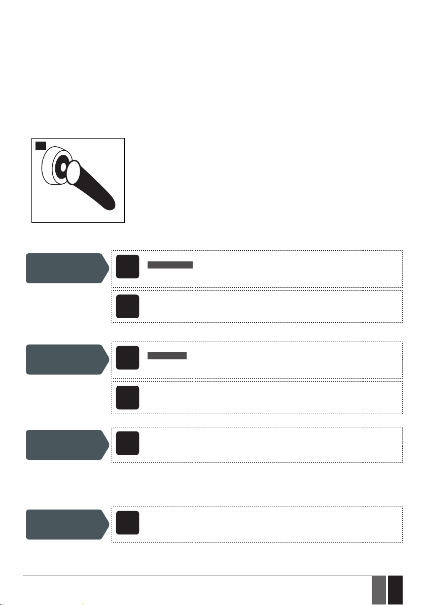
An iButton key is a unique 64-bit ID code containing chip enclosed in a stainless steel tab usually implemented in a small plastic holder.
ESIM4 system supports up to 8 iButton keys each holding a unique identity code (ID), which is used for system arming and disarming (see
15. ARMING AND DISARMING).
For more details on how to wire the iButton key reader, please refer to 2.3. Wiring Diagrams.
10.2.3.1. Adding and Removing iButton Keys
To add an iButton key to the system, do the following:
1) Enable Programming mode.
2) Touch the key to the iButton key reader when the system is disarmed.
17
3) The successfully added iButton key will be indicated by short beeps emitted by the system’s buzzer (if any)
4) Add as many iButton keys as necessary – touch one key after another to the reader – until the number of 8 keys is reached.
SMS text message content:
Enable Programming
mode
ssss_KEY:START
SMS
Value: ssss – 4-digit SMS password.
Example: 1111_KEY:START
Cong
This operation may be carried out from the PC using the ELDES Conguration Tool software.
Tool
When adding of iButton keys is complete, please disable Programming mode.
SMS text message content:
Disable Programming
mode
If the iButton key is lost or stolen, due to security reasons it is highly recommended to remove it from the system
Remove iButton key
from the system
10.2.3.2. iButton Key Names
When the system is armed or disarmed by iButton key, the system sends a conrmation by SMS text message to listed user phone number.
The SMS text message contains system status as well as it may contain a user name, set to the iButton key.
Manage iButton key
name
ESIM4 Manual v1.5
ssss_KEY:END
SMS
Value: ssss – 4-digit SMS password.
Example: 1111_KEY:END
Cong
This operation may be carried out from the PC using the ELDES Conguration Tool software.
Tool
Cong
This operation may be carried out from the PC using the ELDES Conguration Tool software.
Tool
Cong
This operation may be carried out from the PC using the ELDES Conguration Tool software.
Tool
23
23EN
Page 24
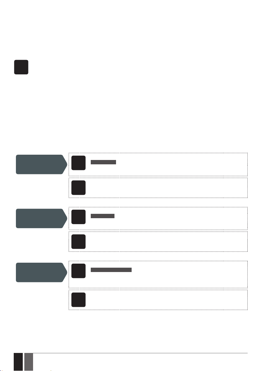
10.3. Alarm/Restore Notications
In the event of input alarm or restore, the system can notify the listed user phone number by the following methods that can be used
individually or simultaneously:
• SMS text message.
• Phone call.
The system supports input alarm/restore notication delivery restriction feature by time. For more details, please refer to to 12. ALARM/
RESTORE NOTIFICATION SCHEDULER.
By default, in the event of input alarm or restore, the system will follow this pattern:
SMS
1) The system attempts to send an SMS text message containing input alarm/restore text to the rst listed user phone
number only.
2) If the user phone number is unavailable and the system fails to receive the SMS delivery report within 45 seconds, it will
attempt to send the SMS text message to the next listed user phone number. The system may fail to deliver the SMS text
message to the listed user phone number due to the following reasons:
• user’s mobile phone has been switched o.
• user’s mobile phone has been out of GSM signal coverage.
• alarm/restore notication scheduler has not yet come into eect, if enabled.
3) The system will continue sending the SMS text message to the next listed user phone numbers in the priority order until
one is available. The system sends the SMS text message only once and will not return to the rst user phone number if
the last one was unavailable.
4) If the system ends up with all unsuccessful attempts, it will queue up the event in the event memory and attempt to send
all the queued up events by SMS text message to the listed user phone number in accordance with the set up period and
number of attempts (see 18. EVENT MEMORY).
To manage input alarm and restore SMS text messages, please refer to the following conguration methods.
SMS text message content:
Disable input alarm
notication
ssss_SAZi:OFF
SMS
Value: ssss – 4-digit SMS password; i – input number, range – [1... 4].
Example: 1111_SAZ1:OFF
Cong
This operation may be carried out from the PC using the ELDES Conguration Tool software.
Tool
Enable input alarm
notication
Set input alarm text
24
24 EN
SMS text message content:
ssss_SAZi:ON
SMS
Value: ssss – 4-digit SMS password; i – input number, range – [1... 4].
Example: 1111_SAZ4:ON
Cong
This operation may be carried out from the PC using the ELDES Conguration Tool software.
Tool
SMS text message content:
ssss_TAZi:in-alarm-text
SMS
Value: ssss – 4-digit SMS password; i – input number, range – [1... 4]; in-alarm-text – up to 23
characters input alarm text.
Example: 1111_TAZ3:Alarm Z3
Cong
This operation may be carried out from the PC using the ELDES Conguration Tool software.
Tool
ESIM4 Manual v1.5
Page 25
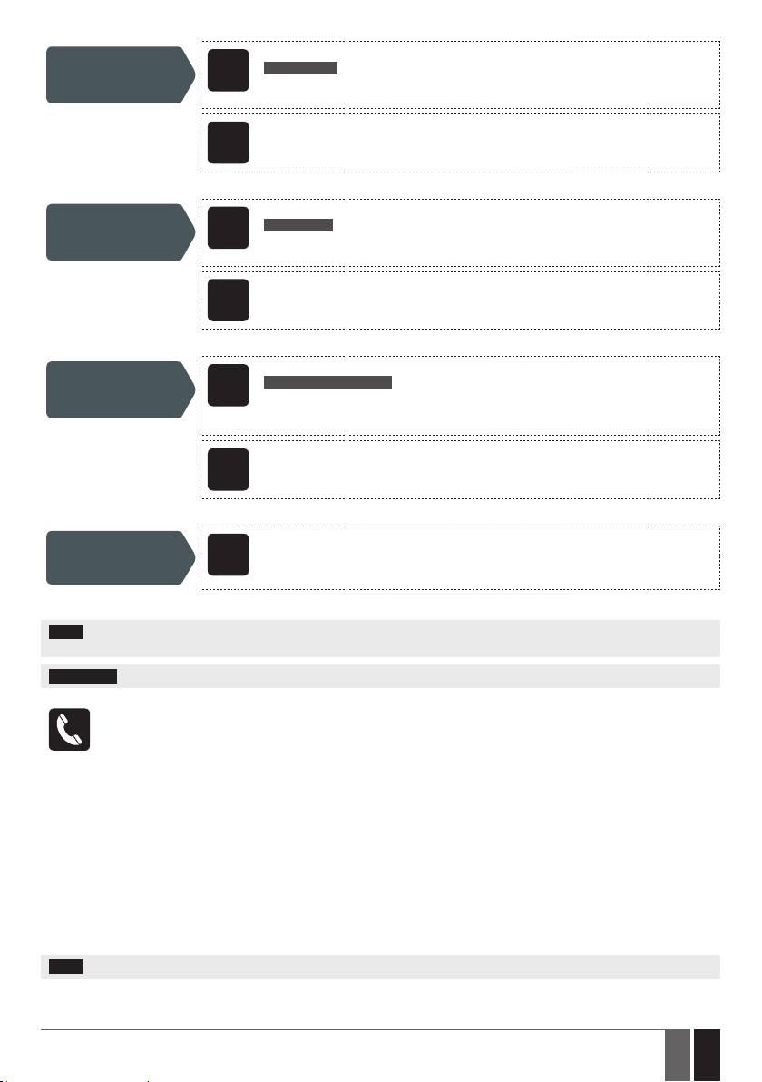
Disable input restore
notication
Enable input restore
notication
Set input restore text
SMS text message content:
ssss_SRZi:OFF
SMS
Value: ssss – 4-digit SMS password; i – input number, range – [1... 4]
Example: 1111_SRZ2:OFF
Cong
This operation may be carried out from the PC using the ELDES Conguration Tool software.
Tool
SMS text message content:
ssss_SRZi:ON
SMS
Value: ssss – 4-digit SMS password; i – input number, range – [1... 4]
Example: 1111_SRZ3:ON
Cong
This operation may be carried out from the PC using the ELDES Conguration Tool software.
Tool
SMS text message content:
ssss_TRZi:in-restore-text
SMS
Value: ssss – 4-digit SMS password; i – input number, range – [1... 4]; in-restore-text – up to
23 characters input restore text.
Example: 1111_TRZ1:Restore Z1
Cong
This operation may be carried out from the PC using the ELDES Conguration Tool software.
Tool
View input alarm/
restore notication
parameters
NOTE: The system will NOT store the alarm/restore event in the event memory if the event has occurred while the alarm/restore notica-
tion scheduler, if enabled, has not yet come into eect.
ATTENTION: Colon, dash, comma characters are NOT allowed in the input alarm/restore notication texts.
The system comes equipped with ringing the listed user phone number (by default – disabled) in the event of input alarm/
restore. If enabled, the system will follow this pattern:
1) The system attempts to ring the rst listed user phone number.
2) When the call is answered, the user will be able to hear short beeps reecting the number of the violated input (one
beep = input Z1; two beeps = input Z2). Overall the user will be able to listen on the mobile phone for 60 seconds to what
is happening in the area, surrounding the system (see 19. REMOTE LISTENING).
3) The system will dial the next listed user phone number if the previous user was unavailable due to the following reasons:
• mobile phone has been switched o.
• mobile phone has been out of GSM signal coverage.
• has provided “busy” signal.
• user did not answer the call after several rings, predetermined by the GSM operator.
4) The system will continue dialing the next listed user phone numbers in the priority order until one is available.
5) The system dials only once and will not return to the rst user phone number if the last one was unavailable. The system
will not dial the next listed user phone number if the previous one was available, but rejected the phone call.
NOTE: Violated input number indication by short beeps apply to input Z1 and input Z2 only.
ESIM4 Manual v1.5
Cong
This operation may be carried out from the PC using the ELDES Conguration Tool software.
Tool
25
25EN
Page 26
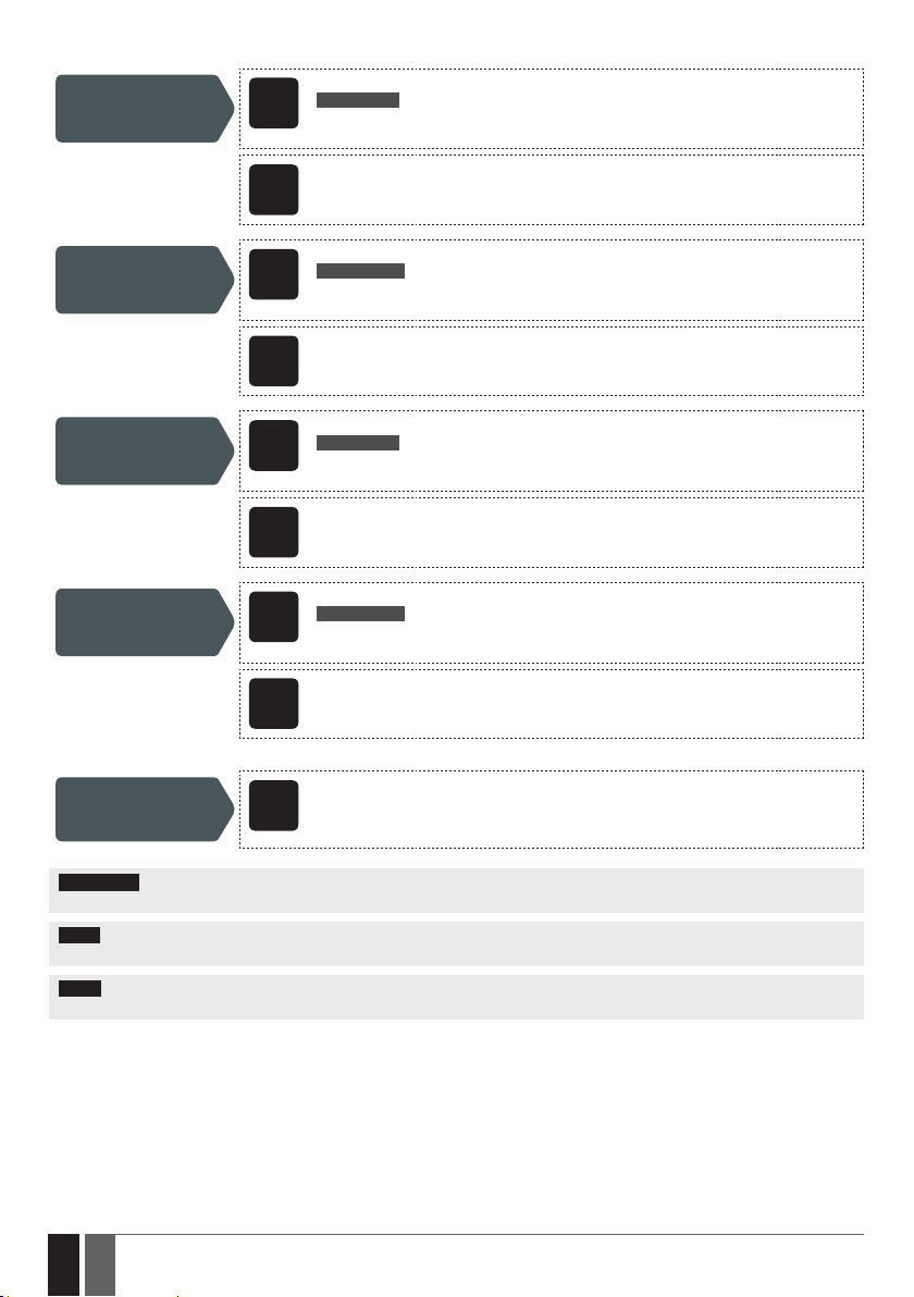
To manage calls in the event of input alarm and restore, please refer to the following conguration methods.
SMS text message content:
Enable call in the
event of input alarm
Disable call in the
event of input alarm
Enable call in the
event of input restore
Disable call in the
event of input restore
ssss_CAZi:ON
SMS
Value: ssss – 4-digit SMS password; i – input number, range – [1... 4].
Example: 1111_CAZ2:ON
Cong
This operation may be carried out from the PC using the ELDES Conguration Tool software.
Tool
SMS text message content:
ssss_CAZi:OFF
SMS
Value: ssss – 4-digit SMS password; i – input number, range – [1... 4].
Example: 1111_CAZ3:OFF
Cong
This operation may be carried out from the PC using the ELDES Conguration Tool software.
Tool
SMS text message content:
ssss_CRZi:ON
SMS
Value: ssss – 4-digit SMS password; i – input number, range – [1... 4].
Example: 1111_CRZ1:ON
Cong
This operation may be carried out from the PC using the ELDES Conguration Tool software.
Tool
SMS text message content:
ssss_CRZi:OFF
SMS
Value: ssss – 4-digit SMS password; i – input number, range – [1... 4].
Example: 1111_CRZ1:OFF
Cong
This operation may be carried out from the PC using the ELDES Conguration Tool software.
Tool
View input alarm/
restore notication
parameters
ATTENTION: Input alarm/restore notications do NOT apply when input Z2 is set up to operate in Temperature Sensor or iButton Key mode.
For more details, please refer to 10.2.2. Temperature Sensor Mode and 10.2.3. iButton Key Mode.
NOTE: If the system ends up with all unsuccessful attempts to ring the preset user phone number, it will NOT store the event in the event
memory.
NOTE: The system will NOT ring the preset user phone number nor store the alarm/restore event in the event memory if the event has
occurred while the alarm/restore notication scheduler, if enabled, has not yet come into eect.
10.3.1. Alarm Delay
The system comes equipped with alarm/restore notication delay feature allowing to limit alarm and restore notication delivery to the
listed user phone number within a specied time-frame.
By default, the alarm delay feature is disabled. Once a delay period is set up for a certain input or shock sensor, by violating/restoring the
input or shock sensor after arming the system and/or on the rst system run, the system will instantly transmit a notication to the listed
user phone number. The system will ignore a repeated violation of the same input/shock sensor while the delay period is in progress. Once
the delay period has expired, the input/shock sensor violation will lead to notication delivery to the listed user phone number.
26
26 EN
Cong
This operation may be carried out from the PC using the ELDES Conguration Tool software.
Tool
ESIM4 Manual v1.5
Page 27
11. SHOCK SENSOR
ESIM4 has a built-in shock sensor that detects the surface vibrations of the location where the device is installed. This feature allows to
receive the alarm/restore notications by SMS text message to the listed user phone number in accordance with the number of set up
shakes in a certain time period (by default – for alarm event: more than 10 shakes in 15 seconds; for restore event: up to 30 shakes in 40
seconds).
The system supports shock sensor alarm/restore notication delivery restriction feature by time. For more details, please refer to to 12.
ALARM/RESTORE NOTIFICATION SCHEDULER.
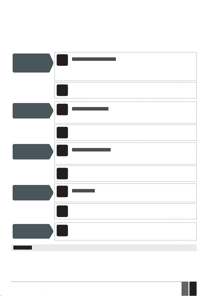
By default, the shock sensor is disabled. To enable/disable the shock sensor, set a dierent number of shakes, time period, manage alarm/
restore SMS text messages and manage alarm delay duration, please refer to the following conguration methods.
Enable shock sensor
and set number of
shakes and period for
alarm/restore event
Set shock sensor
alarm text
Set shock sensor
restore text
SMS text message content:
ssss_SHOCK:alms-almp;rets-retp
SMS
Value: ssss – 4-digit SMS password; alms – minimum number of shakes for alarm event occur-
rence, range – [1... 1000]; almp – time period for alarm event occurrence, range – [1... 1000]
seconds; rets – maximum number of shakes for restore event occurrence, range – [1... 1000];
retp – time period for restore event occurrence, range – [1... 1000] seconds.
Example: 1111_SHOCK:30-45;48-59
Cong
This operation may be carried out from the PC using the ELDES Conguration Tool software.
Tool
SMS text message content:
ssss_TAS:shock-alarm-text
SMS
Value: ssss – 4-digit SMS password; shock-alarm-text - up to 23 characters shock sensor
alarm text.
Example: 1111_TAS:Shock sensor alarm
Cong
This operation may be carried out from the PC using the ELDES Conguration Tool software.
Tool
SMS text message content:
ssss_TRS:shock-restore-text
SMS
Value: ssss – 4-digit SMS password; shock-restore-text - up to 23 characters shock sensor
restore text.
Example: 1111_TRS:Shock sensor restore
Cong
This operation may be carried out from the PC using the ELDES Conguration Tool software.
Tool
SMS text message content:
ssss_SHOCK:OFF
Disable shock sensor
View shock sensor
parameters
ATTENTION: Colon, dash, comma characters are NOT allowed in the shock sensor alarm/restore notication texts.
See also 10.3.1. Alarm Delay.
ESIM4 Manual v1.5
SMS
Value: ssss – 4-digit SMS password.
Example: 1111_SHOCK:OFF
Cong
This operation may be carried out from the PC using the ELDES Conguration Tool software.
Tool
Cong
This operation may be carried out from the PC using the ELDES Conguration Tool software.
Tool
27
27EN
Page 28
12. ALARM/RESTORE NOTIFICATION SCHEDULER
The system supports a scheduler that allow to set up a period of time in day to restrict input and shock sensor alarm/restore notication
delivery by SMS text message and input alarm/restore phone call to the listed user phone number. The scheduler includes the following
parameters:
• Status – Determines whether the scheduler will apply or not. Once enabled, the system will be able to deliver input alarm/restore
notications only when the scheduler comes into eect.
• Start: Hour | Minutes – Determines the point in time when the system is permitted to deliver alarm/restore notications.
• End: Hour | Minutes – Determines the point in time when the system is denied to deliver alarm/restore notications.
By default, the scheduler is disabled and unset. To enable/disable and set up the scheduler, please refer to the following conguration
methods.
SMS text message content:
Enable and set up
scheduler
Disable scheduler
ssss_ETIME:hr:mn_ hr:mn
SMS
Value: ssss – 4-digit SMS password; hr – hours, range – [00... 23]; mn – minutes, range – [00...
59].
Example: 1111_TIME:08:00_19:15
Cong
This operation may be carried out from the PC using the ELDES Conguration Tool software.
Tool
SMS text message content:
ssss_ETIME:OFF
SMS
Value: ssss – 4-digit SMS password.
Example: 1111_CRZ1:OFF
Cong
This operation may be carried out from the PC using the ELDES Conguration Tool software.
Tool
View scheduler
settings
28
28 EN
Cong
This operation may be carried out from the PC using the ELDES Conguration Tool software.
Tool
ESIM4 Manual v1.5
Page 29
13. OUTPUT
The system comes equipped with 1 open collector output C1 designed for electrical appliance connection. Normally, the output can be used
to open/close garage doors, activate lights, heating, watering and much more. When a output turns ON, the system triggers any device or
relay connected to it.
When input Z2 is operating in Temperature Sensor mode or iButton Key mode, C1 converts to +4V power supply output terminal for
temperature sensor or buzzer connection respectively. In such case C1 terminal can not be used as open-collector output. For more details,
please refer to 10.2.2. Temperature Sensor Mode and 10.2.3. iButton Key Mode.
For more details on how to wire the output, please refer to 2.3. Wiring Diagrams.
13.1. Output Name
The output has a name that can be customized by the user. Typically, the name species a device type connected to the output, for
example: Lights.
By default, output C1 name is Output1. To rename the output, please refer to the following conguration methods.
SMS text message content:
ssss_TC1:out-name
Rename output
View output name
SMS
Value: ssss – 4-digit SMS password; out-name – up to 23 characters output name
Example: 1111_TC1:Lamp
Cong
This operation may be carried out from the PC using the ELDES Conguration Tool software.
Tool
SMS text message content:
ssss_STATUS
SMS
Value: ssss – 4-digit SMS password.
Example: 1111_STATUS
Cong
This operation may be carried out from the PC using the ELDES Conguration Tool software.
Tool
ATTENTION: Colon, dash, comma characters are NOT allowed in the output name.
For more details on how to view system’s information that may include output name, please refer to 16. SYSTEM INFORMATION. STATUS SMS.
13.2. Turning Output ON and OFF
By default, the output is turned OFF. To instantly turn ON/OFF the output and set its state to ON/OFF when the system starts-up, please
refer to the following conguration methods.
Turn ON output / Set
output start-up state
as ON
ESIM4 Manual v1.5
SMS text message content:
ssss_C1:ON
SMS
Value: ssss – 4-digit SMS password.
Example: 1111_C1:ON
Cong
This operation may be carried out from the PC using the ELDES Conguration Tool software.
Tool
29
29EN
Page 30
Turn OFF output / Set
output start-up state
as OFF
To instantly turn ON the output for a determined time period and automatically turn it OFF when the time period expires, please refer to
the following conguration methods.
Turn ON output for
time period in seconds
Turn ON output for
time period in minutes
To instantly turn OFF the output for a determined time period and automatically turn it ON when the time period expires, please refer to
the following conguration methods.
Turn OFF output for
time period in seconds
SMS text message content:
ssss_C1:OFF
SMS
Value: ssss – 4-digit SMS password.
Example: 1111_C1:OFF
Cong
This operation may be carried out from the PC using the ELDES Conguration Tool software.
Tool
SMS text message content:
ssss_C1:ON:time-per
SMS
Value: ssss – 4-digit SMS password; time-per – time period, range – [1... 4294967295] sec-
onds.
Example: 1111_C1:ON:50
Cong
This operation may be carried out from the PC using the ELDES Conguration Tool software.
Tool
SMS text message content:
ssss_C1:ON:time-perM
SMS
Value: ssss – 4-digit SMS password; time-per – time period, range – [1... 71582788] minutes.
Example: 1111_C1:ON:7M
Cong
This operation may be carried out from the PC using the ELDES Conguration Tool software.
Tool
SMS text message content:
ssss_C1:OFF:time-per
SMS
Value: ssss – 4-digit SMS password; time-per – time period, range – [1... 4294967295] sec-
onds.
Example: 1111_C1:ON:27
Turn OFF output for
time period in minutes
30
30 EN
Cong
This operation may be carried out from the PC using the ELDES Conguration Tool software.
Tool
SMS text message content:
ssss_C1:OFF:time-perM
SMS
Value: ssss – 4-digit SMS password; time-per – time period, range – [1... 71582788] minutes.
Example: 111_C1:OFF:5M
Cong
This operation may be carried out from the PC using the ELDES Conguration Tool software.
Tool
ESIM4 Manual v1.5
Page 31

SMS text message content:
ssss_STATUS
View output status
NOTE: The output can be turned ON for a determined time period only when it is in OFF state
NOTE: The output can be turned OFF for a determined time period only when it is in ON state
For more details on how to view system’s information that may include output status, please refer to 16. SYSTEM INFORMATION.
STATUS SMS.
SMS
Value: ssss – 4-digit SMS password.
Example: 1111_STATUS
Cong
This operation may be carried out from the PC using the ELDES Conguration Tool software.
Tool
ESIM4 Manual v1.5
31
31EN
Page 32
14. BATTERY LEVEL MONITORING
The system supports battery level monitoring feature allowing notify the listed user by SMS text message when a set up low battery level
is reached (by default – 5%).
By default, low battery notication is disabled. To enable/disable this notication, set up a dierent low battery level and/or notication
text, please refer to the following conguration methods.
Enable Low Battery
notication and set
low battery level
Set Low Battery
notication text
Disable Low Battery
notication
SMS text message content:
ssss_LOWB:lev
SMS
Value: ssss – 4-digit SMS password; lev – low battery level, range – [1... 100] %.
Example: 1111_LOWB:3
Cong
This operation may be carried out from the PC using the ELDES Conguration Tool software.
Tool
SMS text message content:
ssss_TLOWB:lowb-text
SMS
Value: ssss – 4-digit SMS password; lowb-text – up to 23 characters Low Battery noti cation
text.
Example: 1111_TLOWB:Low battery
Cong
This operation may be carried out from the PC using the ELDES Conguration Tool software.
Tool
SMS text message content:
ssss_LOWB:OFF
SMS
Value: ssss – 4-digit SMS password.
Example: 1111_LOWB:OFF
Cong
This operation may be carried out from the PC using the ELDES Conguration Tool software.
Tool
SMS text message content:
ssss_STATUS
View battery level
View battery
level monitoring
parameters
ATTENTION: Colon, dash, comma characters are NOT allowed in Low Battery notication text.
32
32 EN
SMS
Value: ssss – 4-digit SMS password.
Example: 1111_STATUS
Cong
This operation may be carried out from the PC using the ELDES Conguration Tool software.
Tool
Cong
This operation may be carried out from the PC using the ELDES Conguration Tool software.
Tool
ESIM4 Manual v1.5
Page 33
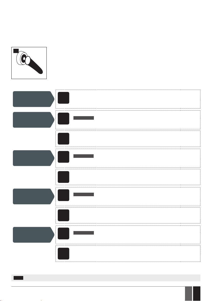
15. ARMING AND DISARMING
ESIM4 comes equipped with mini-alarm system features allowing arming and disarming. Before using this feature, the iButton Key mode
must be selected for Input Z2 and iButton key (-s) must be added to the system. For more details on iButton key management, please refer
to 10.2.3. iButton Key Mode.
To instantly arm or disarm the system, touch the iButton key reader by any of 8 available iButton keys. By default, when the iButton key is
touched to the iButton key reader, the buzzer (see 13. OUTPUT) will emit short beeps followed by SMS text message notication ARMING
or DISARMING respectively. The notication will be simultaneously delivered to all listed user phone numbers that are enabled to receive
arm and/or disarm notications.
18
To modify the content of the notication, manage the arm or disarm notication delivery for a certain listed user phone number and disable
or enable the buzzer, please refer to the following conguration methods.
Manage arm and
disarm notication
text
Disable arm
notication for
individual user
Enable arm
notication for
individual user
Disable disarm
notication for
individual user
Enable disarm
notication for
individual user
Cong
This operation may be carried out from the PC using the ELDES Conguration Tool software.
Tool
SMS text message content:
ssss_NRup:A:0
SMS
Value: ssss – 4-digit SMS password; up – user phone number slot, range – [1... 10];
Example: 1111_NR5:A:0
Cong
This operation may be carried out from the PC using the ELDES Conguration Tool software.
Tool
SMS text message content:
ssss_NRup:A:1
SMS
Value: ssss – 4-digit SMS password; up – user phone number slot, range – [1... 10];
Example: 1111_NR10:A:1
Cong
This operation may be carried out from the PC using the ELDES Conguration Tool software.
Tool
SMS text message content:
ssss_NRup:D:0
SMS
Value: ssss – 4-digit SMS password; up – user phone number slot, range – [1... 10];
Example: 1111_NR6:D:0
Cong
This operation may be carried out from the PC using the ELDES Conguration Tool software.
Tool
SMS text message content:
ssss_NRup:D:0
SMS
Value: ssss – 4-digit SMS password; up – user phone number slot, range – [1... 10];
Example: 1111_NR4:D:1
Cong
This operation may be carried out from the PC using the ELDES Conguration Tool software.
Tool
When attempting to arm the system in case of violated input presence, the system will arm the system followed by instant alarm
notication. To avoid such cases, please restore the input/shock sensor before arming the system.
NOTE: When the system is disarmed, any input or shock sensor violation will be ignored.
33
ESIM4 Manual v1.5
33EN
Page 34
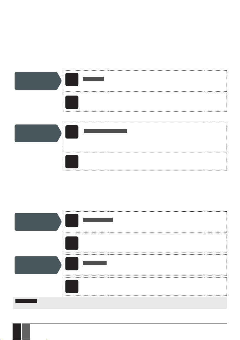
16. SYSTEM INFORMATION. STATUS SMS
The system supports an informational SMS text message identied as the Status SMS, which can be delivered upon request. Once
requested, the system will reply with Status SMS that may provide the following:
• System name.
• System date & time.
• Battery level.
• GSM signal strength.
• System’s internal temperature.
• Name and status (ON/OFF) of the output.
• Input state/value
SMS text message content:
Request for system
information
By default, the aforementioned items, except System name, are excluded from the Status SMS. To include them, please refer to the
following conguration method.
Manage Status SMS
content
16.1. Periodic Status SMS
ssss_STATUS
SMS
Value: ssss – 4-digit SMS password.
Example: 1111_STATUS
Cong
This operation may be carried out from the PC using the ELDES Conguration Tool software.
Tool
SMS text message content:
ssss_TESTM:1;2;3;4;5;6;7;8
SMS
Value: ssss – 4-digit SMS password, 1 - system name; 2 - system date and time; 3 - battery
level; 4 - GSM signal strength; 5 - system‘s internal temperature; 6 - name and status of the
output; 7 - input Z1/Z3 state/value; 8 - input Z2/Z4 state/value.
Example: 1111_TESTM:3;6;8;1;2
Cong
This operation may be carried out from the PC using the ELDES Conguration Tool software.
Tool
Once enabled, the system sends Status SMS to listed user phone number periodically every 1 hour. Typically, this feature is used to verify
the online status of the system.
By default, periodic Status SMS is disabled. To enable/disable periodic Status SMS and/or set a dierent frequency, please refer to the
following conguration methods.
Enable periodic
Status SMS and set
frequency
Disable periodic
Status SMS
ATTENTION: Before using periodic Status SMS, please set the correct system date and time (see 8. DATE AND TIME). Otherwise, the
system will send this SMS text message at the wrong time.
34
34 EN
SMS text message content:
ssss_TEST:frequen
SMS
Value: ssss – 4-digit SMS password; frequen – frequency, range – [1... 1193046] hours.Ex-
ample: 1111_TEST:15550
Cong
This operation may be carried out from the PC using the ELDES Conguration Tool software.
Tool
SMS text message content:
ssss_TEST:OFF
SMS
Value: ssss – 4-digit SMS password.
Example: 1111_TEST:OFF
Cong
This operation may be carried out from the PC using the ELDES Conguration Tool software.
Tool
ESIM4 Manual v1.5
Page 35
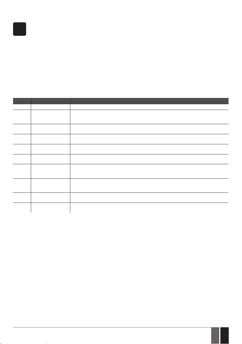
17. SYSTEM NOTIFICATIONS
When an event occurs, the system will follow this pattern:
SMS
The following table provides the description of available system notications sent to the user phone number by SMS text message.
Seq. No. Event Description
1 System Started SMS text message sent to the user on system startup.
2 Low Battery SMS text message sent to the user in case the battery level reaches the set up minimum value.
3 Input Alarm SMS text message sent to the user in case input Z1, Z2, Z3 or Z4 is violated. For more details on how
4 Input Restore SMS text message sent to the user in case input Z1 or Z2 is restored. For more details on how to
5 Shock Sensor Alarm SMS text message sent to the user in case the shock sensor is violated. For more details on how to
6 Shock Sensor Restore SMS text message sent to the user in case the input is restored. For more details on how to manage
7 Periodic Status Status SMS text message sent to the user periodically by the set up frequency (days) and time.
8 Temperature Info SMS text message sent to the user in case the temperature drops below the MIN or rises above
10 Armed SMS text message sent to the user in case the system is armed. For more details on how to manage
11 Disarmed SMS text message sent to the user in case the system is disarmed. For more details on how to
a) The system attempts to send an SMS text message to the rst listed user phone number only.
b) If the user phone number is unavailable and the system fails to receive the SMS delivery report within 45 seconds,
it will attempt to send the SMS text message to the next listed user phone number. The user phone number may be
unavailable due to the following reasons:
• mobile phone has been switched o.
• mobile phone has been out of GSM signal coverage.
c) The system will continue sending the SMS text message to the next listed user phone numbers in the priority order
until one is available. The system sends the SMS text message only once and will not return to the rst user phone
number if the last one was unavailable.
d) If the system ends up with all unsuccessful attempts, it will queue up the event in the event memory and attempt to
send all the queued up events by SMS text message to the listed user phone number in accordance with the set up
period and number of attempts (see 18. EVENT MEMORY).
For more details on how to manage this notication, please refer to 14. BATTERY LEVEL
MONITORING.
to manage this notication, please refer to 10.4. Alarm/Restore Notications.
manage this notication, please refer to 10.3. Alarm/Restore Notications.
manage this notication , please refer to 11. SHOCK SENSOR.
this notication, please refer to 11. SHOCK SENSOR.
For more details on how to manage this notication, please refer to 16. SYSTEM INFORMATION.
STATUS SMS.
the MAX value. For more details on how to manage this notication, please refer to 10.2.2.
Temperature Sensor Mode.
this notification, please refer to 15. ARMING AND DISARMING
manage this notification, please refer to 15. ARMING AND DISARMING
ESIM4 Manual v1.5
35
35EN
Page 36
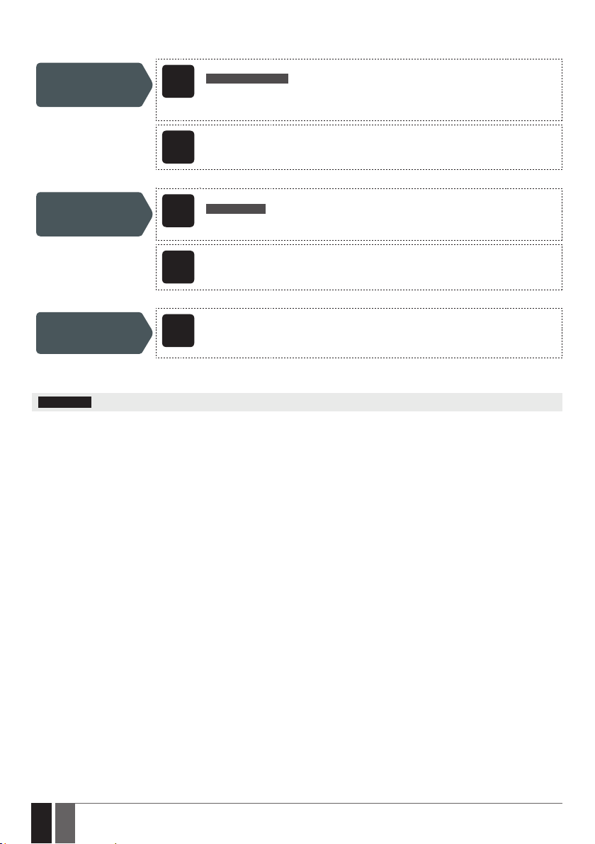
By default, System Started notication is disabled. To enable/disable it and set the text for this notication, please refer to the following
conguration methods.
Enable System
Started notication
and set the text
Disable System
Started notication
SMS text message content:
ssss_SSMS:start-text
SMS
Value: ssss – 4-digit SMS password; start-text – up to 23 characters System Started noti-
cation text.
Example: 1111_SSMS:ESIM4 started
Cong
This operation may be carried out from the PC using the ELDES Conguration Tool software.
Tool
SMS text message content:
ssss_SSMS:OFF
SMS
Value: ssss – 4-digit SMS password.
Example: 1111_SSMS:OFF
Cong
This operation may be carried out from the PC using the ELDES Conguration Tool software.
Tool
View System
Started notication
parameters
For more details on how the system noties the user in the event of input alarm/restore, please refer to 10.3. Alarm/Restore
Notications..
ATTENTION: Colon, dash, comma characters are NOT allowed in System Started notication text.
Cong
This operation may be carried out from the PC using the ELDES Conguration Tool software.
Tool
36
36 EN
ESIM4 Manual v1.5
Page 37
18. EVENT MEMORY
The system comes equipped with event memory that can hold up to 16 events. The event memory is of LIFO (last in, rst out) type that
allows the system to automatically overwrite the oldest events with the latest ones.
The event will queue up in the event memory if the system ends up with all unsuccessful attempts to deliver the SMS text message to the
listed user phone number. The system will attempt to re-transmit all queued up events in accordance with the set up period (by default –
every 10 minutes) and number of attempts (by default – 5 attempts).
By default, event memory is disabled. To enable/disable, clear the event memory or set a dierent re-transmission period and/or number
of attempts, please refer to the following conguration method.
Enable event
memory, set event retransmission attempts
and period
Disable event memory
Clear event memory
SMS text message content:
ssss_LOG:atm-peri
SMS
Value: ssss – 4-digit SMS password; atm – number of attempts, range - [1... 255]; peri - peri-
od, range - [1... 1000] minutes.
Example: 1111_LOG:8-15
Cong
This operation may be carried out from the PC using the ELDES Conguration Tool software.
Tool
SMS text message content:
ssss_LOG:OFF
SMS
Value: ssss – 4-digit SMS password.
Example: 1111_LOG:OFF
Cong
This operation may be carried out from the PC using the ELDES Conguration Tool software.
Tool
Cong
This operation may be carried out from the PC using the ELDES Conguration Tool software.
Tool
View event memory
parameters
NOTE: Event memory feature does NOT apply to calls in case of input alarm/restore.
ESIM4 Manual v1.5
Cong
This operation may be carried out from the PC using the ELDES Conguration Tool software.
Tool
37
37EN
Page 38
19. REMOTE LISTENING
ESIM4 may be equipped with a microphone that allows the user to listen on his mobile phone to what is happening in the area surrounding
the microphone. Remote listening feature can operate under the following conditions:
• The system makes a phone call to a listed user phone number in case of input alarm/restore and the user answers the call (see also
10.3. Alarm/Restore Notications).
• The user dials the system phone number and the system answers the call.
In both cases, the “conversation” will last for up to 60 seconds until the system automatically hangs up.
By default, when the listed user dials the system phone number, the system automatically answers the call. This feature is identied as
Answer Call. To disable, enable the Answer Call feature and set a dierent microphone gain (by default - 12), please refer to the following
conguration methods.
SMS text message content:
Disable Answer Call
feature
Enable Answer Call
feature
Set microphone gain
ssss_ANSWER:OFF
SMS
Value: ssss – 4-digit SMS password.
Example: 1111_ANSWER:OFF
Cong
This operation may be carried out from the PC using the ELDES Conguration Tool software.
Tool
SMS text message content:
ssss_ANSWER:ON
SMS
Value: ssss – 4-digit SMS password.
Example: 1111_ANSWER:ON
Cong
This operation may be carried out from the PC using the ELDES Conguration Tool software.
Tool
SMS text message content:
ssss_MIC:mg
SMS
Value: ssss – 4-digit SMS password; mg – microphone gain, range - [1... 15].
Example: 1111_MIC:10
38
38 EN
Cong
This operation may be carried out from the PC using the ELDES Conguration Tool software.
Tool
ESIM4 Manual v1.5
Page 39

20. TECHNICAL SUPPORT
20.1. Troubleshooting
Indication Possible reason
LED indicator is OFF · Low battery power
Unable to receive any SMS text message reply to
the user phone number and control the device
Received SMS text message “Wrong syntax” · Incorrect SMS text message structure
If your problem could not be xed by the self-guide above, please contact your local distributor. More up to date information about your
device and other products can be found at the manufacturer’s website www.eldes.lt
20.2. Restoring Default Parameters
1. Remove all 4 batteries.
2. Press and hold the DEF button.
3. Connect the device via USB cable to the PC.
4. Wait until the LED indicator quickly ashes several times.
5. Release the DEF button.
6. Parameters restored to default.
· Micro-controller fault
· Insucient SIM card credit balance
· No GSM network signal
· Wrong user phone number
· User phone number is not set
· System is operating in Sleep mode
· Unnecessary space character might have been typed in SMS
text message
20.3. Updating the Firmware via USB Cable
1. Remove all 4 batteries.
2. Short circuit (connect) FW pins.
3. Connect the device via USB cable to the PC.
4. The new window must pop-up where you will nd the .bin le. Otherwise open My Computer and look for CRP DISABLED drive.
5. Delete the .bin le found in the drive.
6. Copy the new rmware .bin le to the very same window.
7. Unplug USB cable.
8. Remove short circuit from FW pins.
9. Firmware updated.
NOTE: It is strongly recommended to restore default parameters after the rmware update.
ESIM4 Manual v1.5
39
39EN
Page 40
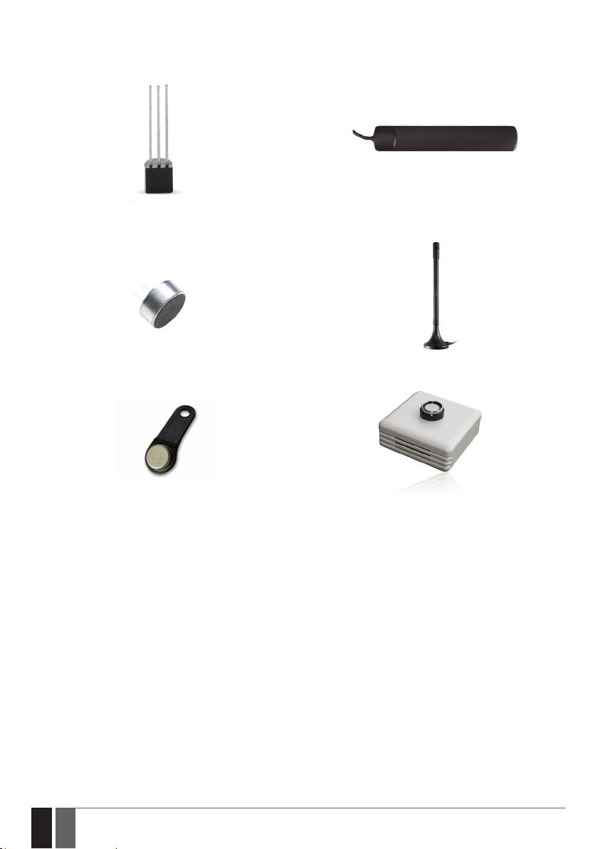
21. RELATED PRODUCTS
DS18S20 - temperature sensor
Microphone Magnet mount straight GSM antenna
Adhesive at GSM antenna
DS1990A-F5 - iButton key
ED1T - plastic enclosure with iButton key reader
and temperature sensor
40
40 EN
ESIM4 Manual v1.5
Page 41

ESIM4 Manual v1.5
41
41EN
Page 42

42
42 EN
ESIM4 Manual v1.5
Page 43

Page 44

Made in the European Union
www.eldes.lt
 Loading...