

Page 1
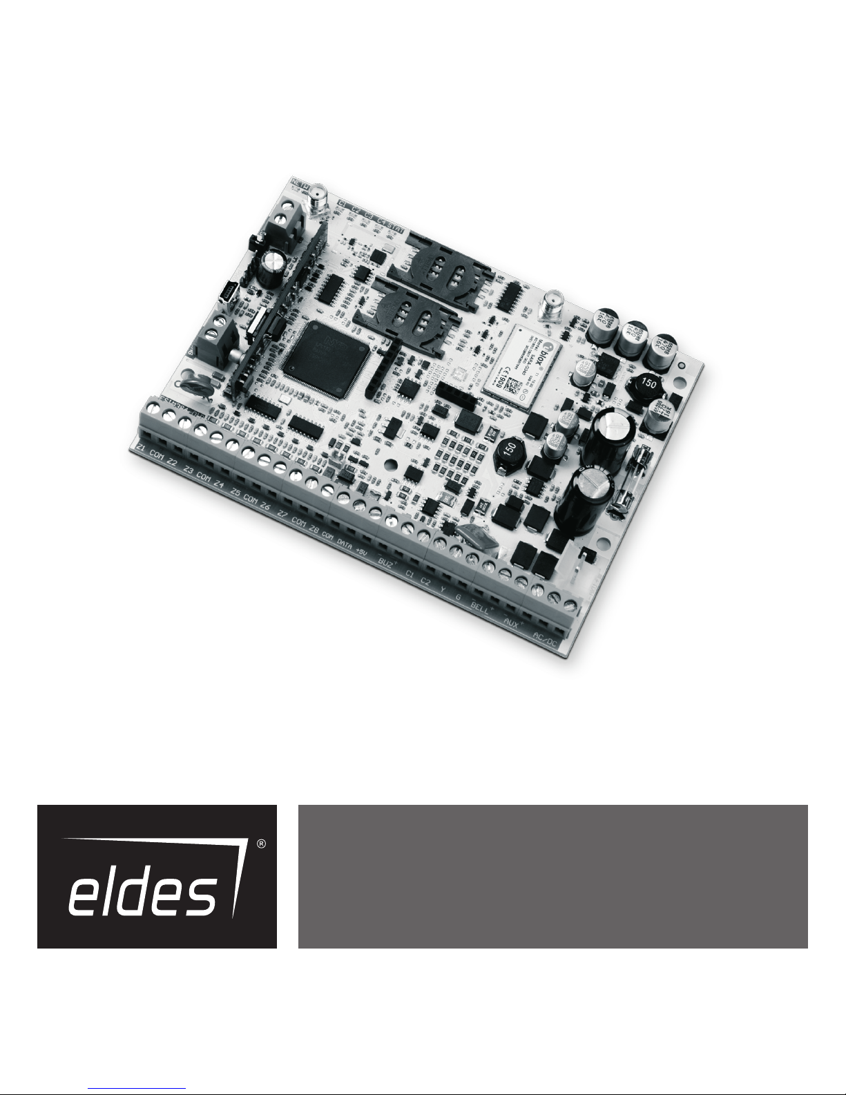
ESIM384
GSM ALARM AND MANAGEMENT SYSTEM
INSTALLATION MANUAL
Page 2
2
2
EN
ESIM384 Installation and Conguration Manual v1.1
Installation Manual v1.0
Valid for ESIM384 v01.00
Safety instructions
Please read and follow these safety guidelines in order to maintain safety of operators and people around:
• GSM alarm & management system ESIM384 (also referenced as “alarm system”, “system” or “device”) has radio transceiver operating in
GSM 850/900/1800/1900 bands.
• DO NOT use the system where it can be interfere with other devices and cause any potential danger.
• DO NOT use the system with medical devices.
• DO NOT use the system in hazardous environment.
• DO NOT expose the system to high humidity, chemical environment or mechanical impacts.
• DO NOT attempt to personally repair the system.
• System label is on the bottom side of the device.
GSM alarm system ESIM384 is a device mounted in limited access areas. Any system repairs must be done only by qualied,
safety aware personnel.
The system must be powered by main 16-24V ~50/60 Hz1.5A max or 18-24V 1,5A max power supply which must be
approved by LST EN 60950-1 standard and be easily accessible nearby the device. When connecting the power supply to the
system, switching the pole terminals places does not have any aect.
Any additional devices linked to the system ESIM384 (computer, sensors, relays etc.) must be approved by LST EN 60950-1
standard.
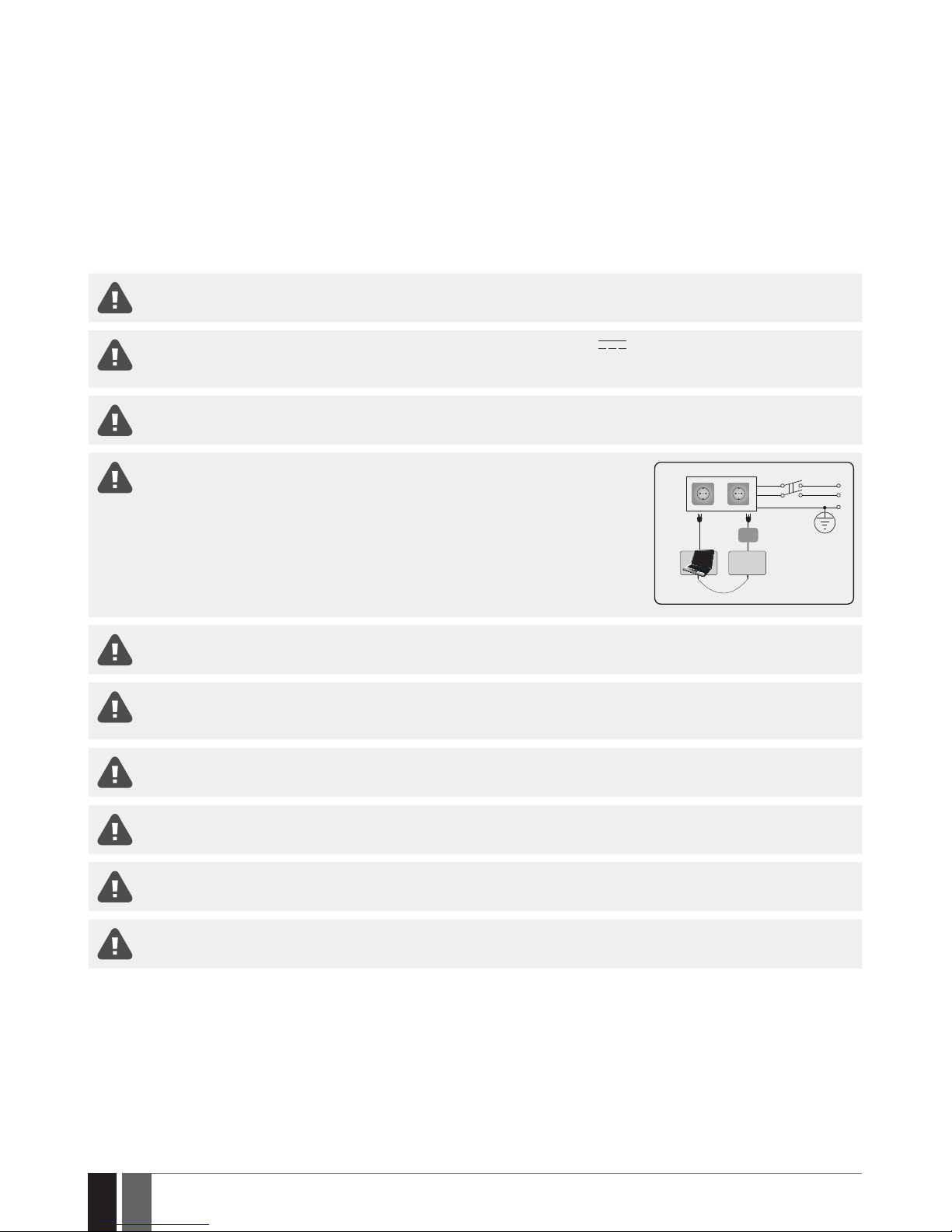
The power supply can be connected to AC mains only inside installation room with automatic 2-pole circuit breaker capable of disconnecting circuit in the event of short circuit
or over-current condition. Open circuit breaker must have a gap between connections
of more than 3mm (0.12in) and the disconnection current 5A.
Phase
AC 230V
50/60Hz/DC 24V
USB cable
Null
PE
ESIM384
AC/DC
Mains power and backup battery must be disconnected before any installation or tuning work starts. The system installation
or maintenance must not be done during stormy conditions
Backup battery must be connected via the connection which in the case of breaking would result in disconnection of one of
battery pole terminals. Special care must be taken when connecting positive and negative battery terminals. Switching the
pole terminals places is NOT allowed.
In order to avoid re or explosion hazards the system must be used only with approved backup battery.
The device is fully turned o by disconnecting 2-pole switch o device of the main power supply and disconnecting backup
battery connector.
Fuse F1 type – Slow Blown 2A. Replacement fuses have to be exactly the same as indicated by the manufacturer.
If you use I security class computer for setting the parameters it must be connected to earth.
Page 3

3
3
EN
ESIM384 Installation and Conguration Manual v1.1
Contents
1. GENERAL INFORMATION .........................................................................................................................................................8
1.1. Functionality ......................................................................................................................................................................................................8
1.2. Compatible Device Overview ...........................................................................................................................................................................8
1.3. Default Parameters and Ways of Parameter Conguration .......................................................................................................................8
2. Technical Specications .......................................................................................................................................................16
2.1. Electrical and Mechanical Characteristics ..................................................................................................................................................16
2.2. Main Unit, LED Indicator and Connector Functionality .............................................................................................................................17
2.3. Wiring Diagrams ..............................................................................................................................................................................................18
3. INSTALLATION ...................................................................................................................................................................... 24
4. GENERAL OPERATIONAL DESCRIPTION ............................................................................................................................... 28
5. CONFIGURATION METHODS ................................................................................................................................................. 29
5.1. SMS Text Messages ........................................................................................................................................................................................ 29
5.2. EKB2 LCD Keypad............................................................................................................................................................................................ 29
5.3. EKB3/EKB3W/EWKB4 LED Keypads ........................................................................................................................................................... 30
5.4. ELDES Conguration software ..................................................................................................................................................................... 30
5.5. System conguration by USB cable..............................................................................................................................................................31
6. SMS PASSWORD AND INSTALLER CODE ................................................................................................................................32
7. SYSTEM LANGUAGE ...............................................................................................................................................................33
8. USER PHONE NUMBERS ....................................................................................................................................................... 34
8.1. User Phone Number Names ..........................................................................................................................................................................35
8.2. System Control from any Phone Number ....................................................................................................................................................35
9. DATE AND TIME ..................................................................................................................................................................... 36
9.1. Automatic Date and Time Synchronization ............................................................................................................................................... 36
10. MASTER AND USER CODES .................................................................................................................................................. 38
10.1. Master and User Code Names ......................................................................................................................................................................40
11. IBUTTON KEYS .......................................................................................................................................................................41
11.1. Adding and Removing iButton Keys ............................................................................................................................................................ 41
11.2. iButton Key Names ......................................................................................................................................................................................... 42
12. ARMING AND DISARMING ..................................................................................................................................................... 43
12.1. Free of Charge Phone Call ............................................................................................................................................................................. 44
12.2. SMS Text Message.......................................................................................................................................................................................... 44
12.3. EKB2 Keypad and User/Master Code .......................................................................................................................................................... 45
12.4. EKB3 Keypad and User/Master Code .......................................................................................................................................................... 47
12.5. EKB3W/EWKB4 Keypads and User/Master Code ...................................................................................................................................... 49
12.6. iButton Key .......................................................................................................................................................................................................51
12.7. EWK1/EWK2 Wireless Keyfob .......................................................................................................................................................................52
12.8. Arm-Disarm by Zone .......................................................................................................................................................................................53
12.9. Automatic Arm/Disarm by Scheduler...........................................................................................................................................................53
12.10. Disabling and Enabling Arm/Disarm Notications ...................................................................................................................................53
13. EXIT AND ENTRY DELAY ........................................................................................................................................................55
14. ZONES .....................................................................................................................................................................................57
14.1. Zone Numbering .............................................................................................................................................................................................57
14.2. Zone Expansion ...............................................................................................................................................................................................57
14.3. 8-Zone Mode .................................................................................................................................................................................................... 57
14.4. ATZ (Advanced Technology Zone) Mode .................................................................................................................................................... 58
14.5. Zone Type Denitions ................................................................................................................................................................................... 58
14.6. Zone Attributes .............................................................................................................................................................................................. 59
14.7. Bypassing and Activating Zones.................................................................................................................................................................. 63
14.8. Zone Names .................................................................................................................................................................................................... 63
14.9. Disabling and Enabling Zones ..................................................................................................................................................................... 64
14.10. Viewing Zone State ...................................................................................................................................................................................... 65
15. STAY MODE ............................................................................................................................................................................ 66
16. TAMPERS ................................................................................................................................................................................67
16.1. Tamper Names ................................................................................................................................................................................................ 68
17. ALARM INDICATIONS AND NOTIFICATIONS FOR USER ....................................................................................................... 69
17.1. Enabling and Disabling Alarm Notications ................................................................................................................................................71
17.2. Audio Files and Introduction Audio ..............................................................................................................................................................72
18. PROGRAMMABLE (PGM) OUTPUTS .......................................................................................................................................73
18.1. PGM Output Numbering ................................................................................................................................................................................. 73
18.2. PGM Output Expansion ...................................................................................................................................................................................73
18.3. PGM Output Names ......................................................................................................................................................................................... 74
Page 4

4
4
EN
ESIM384 Installation and Conguration Manual v1.1
18.4. Disabling and Enabling PGM Outputs ...........................................................................................................................................................74
18.5. Turning PGM Outputs ON and OFF ................................................................................................................................................................74
18.6. PGM Output Control by Event and Scheduler ............................................................................................................................................ 76
18.6.1. PGM Output Actions and System Events.................................................................................................................................................. 76
18.6.2. Schedulers .....................................................................................................................................................................................................77
18.6.3. Additional Conditions ...................................................................................................................................................................................77
18.7. Wireless PGM Output Type Denitions ........................................................................................................................................................77
19. WIRELESS DEVICES ............................................................................................................................................................... 78
19.1. Pairing, Removing and Replacing Wireless Device ................................................................................................................................... 79
19.2. Wireless Device Information.........................................................................................................................................................................80
19.3. Wireless Signal Status Monitoring .............................................................................................................................................................. 80
19.4. Disabling and Enabling Siren if Wireless Signal is Lost ............................................................................................................................ 83
19.5. EKB3W/EWKB4 - Wireless LED Keypad ...................................................................................................................................................... 83
19.6. EWR2 – Wireless Signal Repeater ................................................................................................................................................................ 85
19.7. EWF1/EWF1CO - Wireless Smoke/CO Detector ........................................................................................................................................86
19.8. EW2 - Wireless Zone and PGM Output Expansion Module ...................................................................................................................... 88
19.9. EWM1 - Wireless Power Socket ....................................................................................................................................................................88
19.10. EWKB5 Wireless Touchpad Overview ........................................................................................................................................................ 89
20. WIRED SIREN/BELL ............................................................................................................................................................. 100
20.1. BELL Output Status Monitoring ................................................................................................................................................................. 101
20.2. Bell Squawk ................................................................................................................................................................................................... 101
20.3. Bell Squawk in Stay Mode ........................................................................................................................................................................... 102
20.4. Indication by EWS2 - Wireless Outdoor Siren Indicators ....................................................................................................................... 103
20.5. Indication by EWS3 - Wireless Indoor Siren Indicators ..........................................................................................................................104
21. BACKUP BATTERY, MAINS POWER STATUS MONITORING AND MEMORY......................................................................... 105
21.1. Backup Battery Status Monitoring ............................................................................................................................................................ 105
21.2. Mains Power Status Monitoring ................................................................................................................................................................. 107
22. GSM CONNECTION AND ANTENNA STATUS MONITORING................................................................................................. 109
22.1. GSM Connection Status Monitoring ..........................................................................................................................................................109
22.2. GSM/GPRS antenna Status Monitoring .................................................................................................................................................... 110
23. PARTITIONS ......................................................................................................................................................................... 111
23.1. Zone Partition ................................................................................................................................................................................................111
23.2. User Phone Number Partition .....................................................................................................................................................................111
23.3. Keypad Partition and Keypad Partition Switch .........................................................................................................................................112
23.4. User/Master Code Partition ....................................................................................................................................................................... 113
23.5. iButton Key Partition ................................................................................................................................................................................... 114
23.6. EWK1/EWK2 Wireless Keyfob Partition ................................................................................................................................................... 114
24. TEMPERATURE SENSORS .................................................................................................................................................... 115
24.1. Adding, Removing and Replacing On-Board Dallas Temperature Sensors..........................................................................................115
24.2. Primary and Secondary Temperature Sensors ........................................................................................................................................ 116
24.3. Setting Up MIN and MAX Temperature Thresholds. Temperature Info SMS .......................................................................................117
24.4. Temperature Sensor Names ....................................................................................................................................................................... 118
25. REMOTE LISTENING AND 2-WAY VOICE COMMUNICATION .................................................................................................119
26. SYSTEM INFORMATION. INFO SMS ..................................................................................................................................... 120
26.1. Periodic Info SMS .......................................................................................................................................................................................... 120
27. SYSTEM NOTIFICATIONS .....................................................................................................................................................122
27.1. SMS Text Message Delivery Restrictions ................................................................................................................................................. 133
27.2. SMSC (Short Message Service Center) Phone Number .......................................................................................................................... 133
28. EVENT AND ALARM LOG ..................................................................................................................................................... 134
28.1. Event Log ....................................................................................................................................................................................................... 134
28.2. Alarm Log ....................................................................................................................................................................................................... 135
29. INDICATION OF SYSTEM FAULTS ........................................................................................................................................ 136
30. MONITORING STATION ........................................................................................................................................................ 138
30.1. Data Messages – Events .............................................................................................................................................................................. 139
30.2. Communication ............................................................................................................................................................................................. 145
31. DUAL SIM MANAGEMENT ....................................................................................................................................................157
31.1. Disabled Mode............................................................................................................................................................................................... 157
31.2. Automatic Mode ........................................................................................................................................................................................... 157
32. WIRED DEVICES ................................................................................................................................................................... 158
32.1. RS485 Interface ...........................................................................................................................................................................................158
32.2. 1-Wire Interface ............................................................................................................................................................................................ 167
32.3. Modules Interface ........................................................................................................................................................................................ 167
33. SERVICE MODE .................................................................................................................................................................... 170
34. REMOTE SYSTEM RESTART ................................................................................................................................................ 170
Page 5

5
5
EN
ESIM384 Installation and Conguration Manual v1.1
35. ELDES CLOUD SERVICES ......................................................................................................................................................171
36. TECHNICAL SUPPORT .........................................................................................................................................................172
36.1. Troubleshooting ........................................................................................................................................................................................... 172
36.2. Restoring Default Parameters ................................................................................................................................................................... 172
36.3. Updating the Firmware via USB Cable Locally ........................................................................................................................................ 172
36.4. Updating Firmware via GPRS Connection Remotely .............................................................................................................................. 173
36.5. Frequently Asked Questions ...................................................................................................................................................................... 173
37. RELATED PRODUCTS............................................................................................................................................................175
38. GLOSSARY – APPENDIX 1 .................................................................................................................................................... 178
39. EKB3/EKB3W/EWKB4 COMMANDS - APPENDIX 2 ............................................................................................................ 180
40. SMS COMMANDS - APPENDIX 3 ..........................................................................................................................................191
41. RADIO SYSTEM INSTALLATION AND SIGNAL PENETRATION APPENDIX 4 ................................................................... 194
Page 6

6
6
EN
ESIM384 Installation and Conguration Manual v1.1
TERMS OF USE
The following terms and conditions govern use of the ESIM384 device and contains important information on limitations regarding the
product’s use and function, as well as information on the limitations of the manufacturer’s liability. Please carefully read these terms and
conditions. For more information on your product, please visit www.eldesalarms.com
TECHNICAL SUPPORT
In order to ensure continuous and proper operation of the ESIM384 device and uninterrupted service, it is the responsibility of the User to
make sure that: (I) the product is properly installed, and (II) there is constant internet or GSM connection and electrical supply (low battery
must be replaced in time).
If you experience diculty during the installation or subsequent use of the system, you may contact ELDES, UAB distributor or dealer in
your country/region. For more information see www.eldesalarms.com
WARRANTY PROCEDURES
Warranty and out of warranty service should be obtained by contacting the system integrator/dealer/retailer/e-tailer or distributor where
the customer purchased the product. When requesting for service, the proof of purchase and the product serial number must be provided.
The return of the defective product should be strictly through the original route of purchase, and the customers shall pack the product
appropriately to prevent the returned product from suering in the transportation.
MANUFACTURER WARRANTY
ELDES provides a limited warranty for its products only to the person or entity that originally purchased the product from ELDES or its
authorized distributor or retailer and only in case of defective workmanship and materials under normal use of the system for a period of
twenty four (24) months from the date of shipment by the ELDES, UAB (Warranty Period). Warranty obligations do not cover expandable
materials (power elements and/or batteries), holders and enclosures. The warranty remains valid only if the system is used as intended,
following all guidelines outlined in this manual and in accordance with the operating conditions specied. The warranty is void if the system
has been exposed to mechanical impact, chemicals, high humidity, uids, corrosive and hazardous environments or force majeure factors.
If a hardware defect arises and a valid claim is received within the Warranty Period, at its own discretion, ELDES, UAB will either (a) repair a
hardware defect at no charge, using new or refurbished replacement parts, or (b) exchange the product with a product that is new or which
has been manufactured from new or serviceable used parts and is at least functionally equivalent to the original product, or (c) refund the
purchase price of the product.
LIMITED LIABILITY
The buyer must agree that the system will reduce the risk of theft, burglary or other dangers but does not provide guarantee against such
events. ELDES, UAB will not assume any responsibility regarding personal or property, or revenue loss while using the system. ELDES, UAB
is not aliated with any of the Internet providers, therefore, it shall not responsible for the quality of Internet service.
ELDES, UAB shall also assume no liability due to direct or indirect damage or loss, as well as unreceived income when using the system, including cases, when the damages arise due to the above mentioned risks, when due to breakdown or malfunction the user is not informed
in a timely manner about a risk which has arisen. In any case, the liability of ELDES, UAB, as much as it is allowed by the laws in force, shall
not exceed the price of acquisition of the product.
CONSUMER PROTECTION LAWS
FOR CONSUMERS WHO ARE COVERED BY CONSUMER PROTECTION LAWS OR REGULATIONS IN THEIR COUNTRY OF PURCHASE OR, IF DIFFERENT, THEIR COUNTRY OF RESIDENCE, THE BENEFITS CONFERRED BY THIS WARRANTY ARE IN ADDITION TO ALL RIGHTS AND
REMEDIES CONVEYED BY SUCH CONSUMER PROTECTION LAWS AND REGULATIONS. This warranty grants upon you specic legal
rights, and you may also have other rights that vary by country, state or province.
DISPOSAL AND RECYCLING INFORMATION
The WEEE (Waste Electrical and Electronic Equipment) marking on this product (see left) or its documentation indicates that the
product must not be disposed of together with household waste. To prevent possible harm to human health and/or the environment, the product must be disposed on in an approved and environmentally safe recycling process. For further information
on how to dispose of this product correctly, contact the system supplier, or the local authority responsible for waste disposal
in your area.
Page 7

7
7
EN
ESIM384 Installation and Conguration Manual v1.1
Content of Pack
Item Quantity Item Quantity
1. ESIM384.......................... ...................................1
2. SMA antenna..................... ................................2
3. Back-up battery connection wire ..................1
3. User manual................ .......................................1
5. Resistors 5,6k.......... .......................................16
6. Resistors 3,3k................ .................................8
7. Plastic standos......... ......................................4
These following components are optional (sold separately) and are not included in device’s Content of Pack:
Buzzer;
Microphone.
About Installation Manual
This document describes detailed installation and operation process of alarm system ESIM384. It is very important to read the installation
manual before starting to use the system.
It is strictly forbidden to copy and distribute the information contained in this document or to pass thereof to a third
party without an a priori written authorization obtained from ELDES, UAB. ELDES, UAB reserves the right to update or
modify this document and/or related products without an a priori warning. ELDES, UAB hereby declares that GSM alarm
and management system ESIM384 is in compliance with the essential requirements and other relevant provisions of
the Directive 1999/5/EC. The declaration of conformity is available at www.eldesalarms.com.
Copyright © ELDES, UAB, 2017. All rights reserved
Page 8
8
8
EN
ESIM384 Installation and Conguration Manual v1.1
1. GENERAL INFORMATION
1.1. Functionality
ESIM384 – micro-controller based alarm system for houses, cottages, country homes, garages and other buildings, also capable of managing electrical appliances via cellular GSM/GPRS network. It can also be used as Intercom system.
Examples of using the system:
• Property security.
• Alarm switch.
• Thermostat, heating and air-conditioner control, temperature
monitoring.
• Lighting, garden watering, water pump and other electrical
equipment control via SMS text messages.
• Remote listening to what is happening in the secured area.
• Mains power status notication by SMS text message.
• Two-way intercom device via GSM network.
1.2. Compatible Device Overview
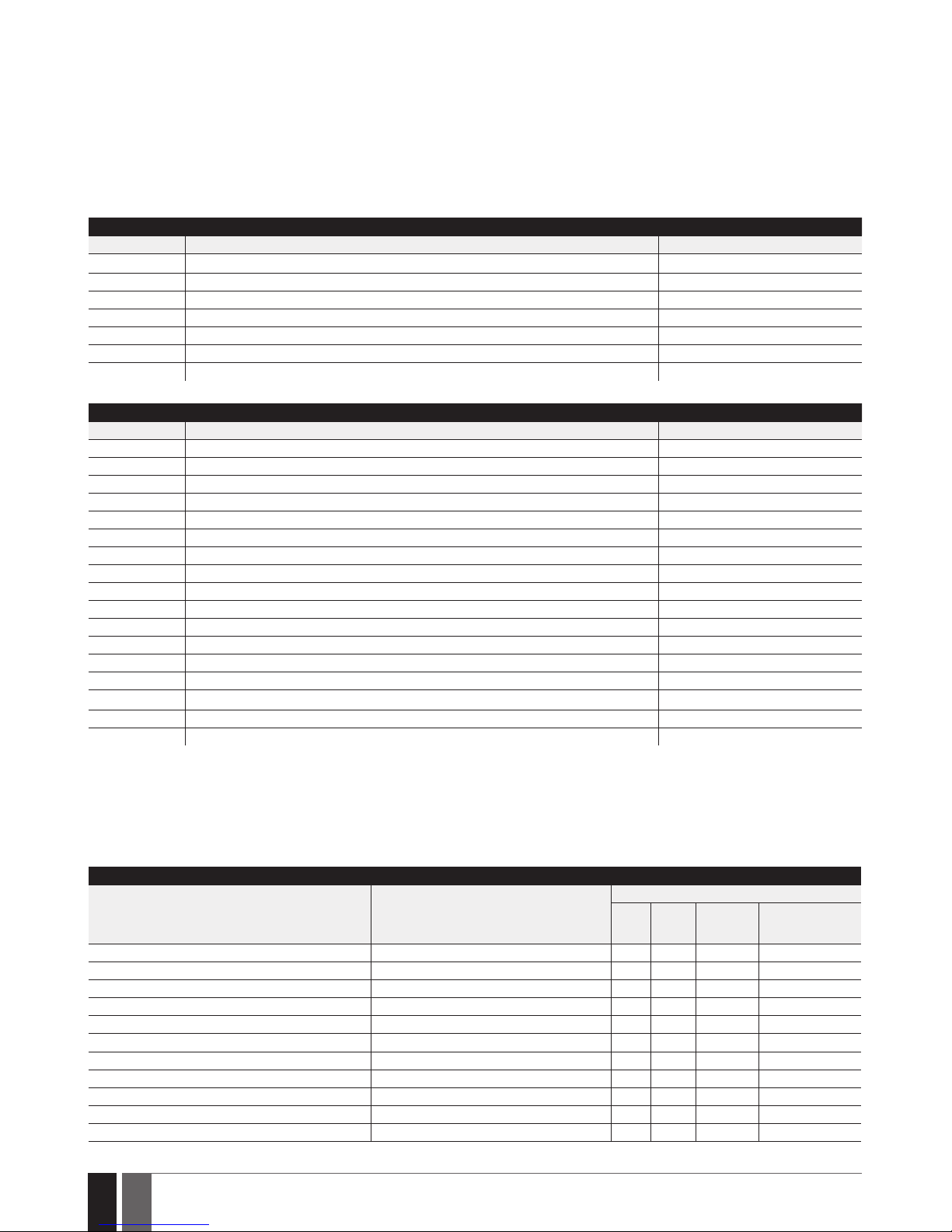
Wired Devices
Device Description Max. Connectible Devices
EKB2 LCD keypad 4*
EKB3 LED keypad 4*
EA1 Audio output module with 3,5mm jack 1**
EA2 Audio amplier module 1W 8 1**
EPGM1 16 zone and 2 PGM output expansion module 2
ELAN3-ALARM Ethernet communicator 1
EPGM8 8 PGM output expansion module 1**
Wireless Devices
Device Description Max. Connectible Devices
EW2 Wireless 2 zone and 2 PGM output expansion module 16*****
EWP2 Wireless motion detector 32***
EWP3 Wireless motion detector 32***
EWD2 Wireless magnetic door contact/shock sensor/ood sensor 32***
EWD3 Wireless magnetic door contact/shock sensor/ood sensor 32***
EWK1**** Wireless keyfob with 4 buttons 5***
EWK2**** Wireless keyfob with 4 buttons 5***
EWS3 Wireless indoor siren 32***
EWK2A**** Wireless keyfob with 1 button 5***
EWS2 Wireless outdoor siren 32***
EKB3W Wireless LED keypad 4***
EWKB4 Wireless LED keypad 4***
EWKB5 Wireless touchpad 4***
EWF1 Wireless smoke detector 32***
EWF1CO Wireless smoke and CO detector 32***
EWR2 Wireless signal repeater 4***
EWM1 Wireless power socket 32***
* - A mixed combination of EKB2 and EKB3 keypads is supported. The combination can consist of up to 4 keypads in total.
** - Only 1 of these modules can be connected at a time if the module slots are implemented in ESIM384 unit.
*** - A mixed combination of wireless devices is supported. The combination can consist of up to 32 wireless devices in total.
**** - A mixed combination of EWK1, EWK2 and EWK2A keyfobs is supported. The combination can consist of up to 5 keyfobs in total.
***** - EW2 creates 4 wireless zones, therefore the max. number of connectible EW2 devices is 16 if no keypad zones, no EPGM1 and no
virtual zones exist in the system’s conguration.
1.3. Default Parameters and Ways of Parameter Conguration
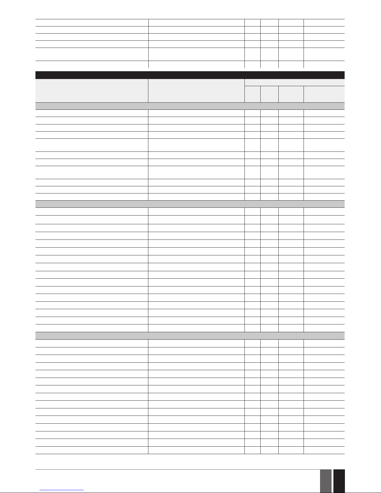
Main Settings
Parameter Default Value
Congurable by:
SMS EKB2
EKB3/
EKB3W/
EWKB4
Conguration
Software
User 1... 10 name N/A
User 1... 10 phone number N/A
User 1... 10 partition Partition 1
User 1...10 - call in case of alarm Enabled
Allow control from any phone number Disabled
SMS password 0000
SMS language Depends on the rmware
Partition 1 name PART1
Partition 2 name PART2
Partition 3 name PART3
Partition 4 name PART4
Page 9
9
9
EN
ESIM384 Installation and Conguration Manual v1.1
Partition 1... 4 exit delay 15 seconds
GSM signal loss indication - delay 180 seconds
GSM signal loss indication – activate output N/A
Dual SIM management – SIM card switch Disabled
Dual SIM management – try to nd operator for a
maximum of
3 time (s)
Dual SIM management – send SMS/call via Currently in use SIM
Main Settings
Parameter Default Value
Congurable by:
SMS EKB2
EKB3/
EKB3W/
EWKB4
Conguration
Software
Passwords/Codes
Installer's code 1470
Duress code N/A
SGS code N/A
Passwords/codes format 4-digit
Prompt additionally for master code when conguring via keypad/software
Disabled
Master code 1111
Master code name N/A
Master code partition
Partition 1, Partition 2, Partition 3, Partition 4
User code 2... 30 N/A
User code 2... 30 name N/A
User code 2... 30 partition Partition 1
Faults
Main power loss Enabled
Low battery Enabled
Battery dead or missing Enabled
Battery failed Enabled
Wired siren failed Enabled
RF jammer detected Enabled
Tamper alarm Enabled
Date/time not set Enabled
GSM connection failed Enabled
GSM antenna failed Enabled
Wireless antenna failed Enabled
Communication bus failed Enabled
Critical CO level Enabled
Wireless power socket fault Enabled
Wireless device low battery Enabled
Communication with MS failed Disabled
Notications
System armed – User 1... 10 Enabled
System armed – SMS delivery report Enabled
System disarmed – User 1... 10 Enabled
System disarmed – SMS delivery report Enabled
General alarm – User 1... 10 Enabled
General alarm – SMS delivery report Enabled
Main power loss/restore – User 1... 10 Enabled
Main power loss/restore – SMS delivery report Enabled
Battery failed – User 1... 10 Enabled
Battery failed – SMS delivery report Enabled
Battery dead or missing – User 1... 10 Enabled
Battery dead or missing – SMS delivery report Enabled
Low battery – User 1... 10 Enabled
Low battery – SMS delivery report Enabled
Siren fail/restore – User 1... 10 Disabled
Page 10

10
10
EN
ESIM384 Installation and Conguration Manual v1.1
Siren fail/restore – SMS delivery report Disabled
RF jammer detected – User 1... 10 Disabled
RF jammer detected – SMS delivery report Disabled
Date/time not set – User 1... 10 Disabled
Date/time not set – SMS delivery report Disabled
GSM connection failed – User 1... 10 Disabled
GSM connection failed – SMS delivery report Disabled
GSM/GPRS antenna fail/restore – User 1... 10 Disabled
GSM/GPRS antenna fail/restore – SMS delivery
report
Disabled
Tamper alarm/restore – User 1... 10 Enabled
Tamper alarm/restore – SMS delivery report Enabled
Communication bus fail/restore – User 1... 10 Enabled
Communication bus fail/restore – SMS delivery
report
Enabled
Temperature info – User 1... 10 Enabled
Temperature info – SMS delivery report Enabled
System started – User 1... 10 Enabled
System started – SMS delivery report Enabled
Periodical info – User 1... 10 Enabled
Periodical info – SMS delivery report Enabled
Wireless signal loss – User 1... 10 Enabled
Wireless signal loss – SMS delivery report Enabled
Unable to arm – User 1... 10 Enabled
Unable to arm – SMS delivery report Enabled
Zone bypass - User 1... 10 Enabled
Zone bypass – SMS delivery report Enabled
Critical CO level - User 1... 10 Enabled
Critical CO level – SMS delivery report Enabled
Wireless socket signal loss/restore - User 1... 10 Disabled
Wireless socket signal loss/restore – SMS delivery
report
Disabled
Report/Control zone triggered - User 1... 10 Enabled
Report/Control zone triggered - SMS delivery
report
Enabled
Incoming SMS forwarding - User 1... 10 Enabled
Incoming SMS forwarding - SMS delivery report Enabled
Wireless communication failed - User 1... 10 Disabled
Wireless communication failed - SMS delivery
report
Disabled
Communication with MS failed - User 1... 10 Disabled
Communication with MS failed - SMS delivery
report
Disabled
Send to all users simultaneously – all notications Disabled
Time Synchronization
Time synchronization Disabled
Phone number of the currently inserted SIM card N/A
Synchronization frequency 30 days
Event Log
Event log Enabled
Zones
Parameter Default Value
Congurable by:
SMS EKB2
EKB3/
EKB3W/
EWKB4
Conguration
Software
On Board
Z1... Z8 zone name Zone1... Zone8
Z1 type Delay
Z1... Z8 zone status Enabled
Z2... Z8 type Instant
Page 11

11
11
EN
ESIM384 Installation and Conguration Manual v1.1
Z1... Z8 delay, ms 800 milliseconds
Z1... Z8 – Stay Disabled
Z1... Z8 – Force Disabled
Z1... Z8 Tamper name Tamper1... Tamper8
Delay-type zone – entry delay 15 seconds
Z1... Z8 partition Partition 1
Z1... Z8 – Shared Disabled
Z1... Z8 – audio track N/A
Z1... Z8 – alarm count to bypass 0
Cross-Zone/Intelli-Zone N/A
Conrmation Timeout 20 seconds
Tamper 1... 8 status Enabled
Z1... Z8 - zone connection type Type 1
Delay becomes Instant in STAY mode Disabled
Chime Enabled
ATZ mode Disabled
Arm-disarm by zone No1... No4 N/A
EPGM1 Module
Zone name Zone X
Zone status Enabled
Type Instant
Delay, ms 800 milliseconds
Stay Disabled
Force Disabled
Tamper name Tamper X
Delay-type zone – entry delay 15 seconds
Partition Partition 1
Shared Disabled
Audio track N/A
Alarm count to bypass 0
Cross-Zone/Intelli-Zone N/A
Conrmation Timeout 20 seconds
Tamper status Enabled
Zone connection type for all EPGM1 zones Type 1
Wireless Devices
Zone name Zone X
Zone status Enabled
Type
Depends on the connected wireless device
model
Stay Disabled
Force Disabled
Tamper name Tamper X
Delay-type zone – entry delay 15 seconds
Partition Partition 1
Shared Disabled
Audio track N/A
Alarm count to bypass 0
Cross-Zone/Intelli-Zone N/A
Conrmation Timeout 20 seconds
Tamper status Enabled
Keypads
Zone name Zone X
Zone status Disabled
Type Instant
Stay Disabled
Force Disabled
Tamper name Tamper X
Delay-type zone – entry delay 15 seconds
Partition Partition 1
Shared Disabled
Audio track N/A
Page 12
12
12
EN
ESIM384 Installation and Conguration Manual v1.1
Alarm count to bypass 0
Cross-Zone/Intelli-Zone N/A
Conrmation Timeout 20 seconds
Tamper status Enabled
Virtual Zones
Zone name Zone X
Zone status Disabled
Type Instant
Force Disabled
Delay-type zone – entry delay 15 seconds
Partition Partition 1
Shared Disabled
Alarm count to bypass 0
Cross-Zone/Intelli-Zone N/A
Conrmation Timeout 20 seconds
Tamper status Enabled
PGM Outputs
Parameter Default Value
Congurable by:
SMS EKB2
EKB3/
EKB3W/
EWKB4
Conguration
Software
On Board
C1... C4 output name Controll1... Controll4
C1... C4 output state OFF
C1... C4 output status Enabled
Using module EPGM8 Disabled
EPGM1 Module
Output name ControllX
State OFF
Status Disabled
Wireless Devices
Output name ControllX
Type
Depends on the connected wireless device model
State OFF
Status Disabled
MS Settings
Parameter Default Value
Congurable by:
SMS EKB2
EKB3/
EKB3W/
EWKB4
Conguration
Software
Management
MS mode Disabled
Main Account 9999
GSM and SMS – attempts 3
GSM and SMS – tel. number 1... 3 N/A
PSTN – treat PSTN call as user call Disable
PSTN – attempts 3
PSTN – tel. number 1... 3 N/A
CSD – attempts 3
CSD – tel. number 1... 5 N/A
Parallel data transfer via IP network Disabled
IP Server 1... 3 – IP attempts 3
IP Server 1... 3 – test period 180 seconds
IP Server 1... 3 – protocol UDP
IP Server 1...3 – account 9999
IP Server 1...3 – unit ID 0000
IP Server 1... 3 – communication protocol EGR100
IP Server 1... 3 – server IP 0.0.0.0
IP Server 1... 3 – server port 20000
IP Server 1... 3 – encryption key - status Disabled
Page 13

13
13
EN
ESIM384 Installation and Conguration Manual v1.1
IP Server 1... 3 – encryption key 0000
Communication - primary IP Server 1 (GPRS)
Communication – backup 1... 5 N/A
Retry after delay N/A
Delay after last communication attempt 1200 seconds
SIA IP protocol settings - encryption Disabled
SIA IP protocol settings – encryption key 0000
SIA IP protocol settings – account prex N/A
SIA IP protocol settings – receiver number N/A
SIA IP protocol settings – use time stamp Enabled
SIA IP protocol settings – Contact ID ping Disabled
SIA IP protocol settings – data message Event: 1602, partition: 01, user/zone: 000
Data Messages
Burglary alarm/restore – code 130
Burglary alarm/restore – status Enabled
Main power loss/restore – code 301
Main power loss/restore – status Enabled
Armed/disarmed by user – code 401
Armed/disarmed by user – status Enabled
Test event – code 602
Test event – status Enabled
Battery failed – code 309
Battery failed – status Enabled
Battery dead or missing – code 311
Battery dead or missing – status Enabled
Tamper alarm/restore – code 144
Tamper alarm/restore – status Enabled
Instant Silent zone alarm/restore – code 14 6
Instant Silent zone alarm/restore – status Enabled
Kronos ping – code 602
Kronos ping – status Enabled
System started – code 900
System started – status Enabled
24H zone alarm/restore – code 133
24H zone alarm/restore – status Enabled
Fire zone alarm/restore – code 110
Fire zone alarm/restore – status Enabled
Low battery – code 302
Low battery – status Enabled
Temperature exceeded – code 158
Temperature exceeded – status Enabled
Temperature fallen – code 159
Temperature fallen – status Enabled
Wireless signal loss/restore – code 381
Wireless signal loss/restore – status Enabled
Disarmed by user (duress code) – code 121
Disarmed by user (duress code) – status Enabled
SGS code entered – code 463
SGS code entered – status Enabled
Armed by user (partial arm) – code 456
Armed by user (partial arm) – status Enabled
RF jammer detected - code 344
RF jammer detected - status Enabled
Siren fail/restore – code 321
Siren fail/restore – status Disabled
Date/time not set – code 626
Date/time not set – status Enabled
GSM connection failed – code 358
GSM connection failed – status Enabled
GSM/GPRS antenna fail/restore – code 359
GSM/GPRS antenna fail/restore – status Disabled
System shutdown – code 414
System shutdown – status Enabled
Communication bus fail/restore – code 330
Page 14
14
14
EN
ESIM384 Installation and Conguration Manual v1.1
Communication bus fail/restore – status Enabled
IP connection failed – code 360
IP connection failed – status Enabled
Zone bypass/Bypassed zone activation – code 570
Zone bypass/Bypassed zone activation – status Enabled
CO sensor lifetime exceeded -code 380
CO sensor lifetime exceeded -status Enabled
Critical CO level - code 162
Critical CO level - status Enabled
Report/Control zone triggered/restored – code 150
Report/Control zone triggered/restored – status Disabled
Armed/disarmed in STAY mode – code 441
Armed/disarmed in STAY mode – status Enabled
Conguration via remote connection started code
412
Conguration via remote connection started status
Disabled
Silent/Panic zone alarm/restore - code 120
Silent/Panic zone alarm/restore - status Enabled
Armed/disarmed automatically - code 403
Armed/disarmed automatically - status Enabled
SMS sending limit reached - code 458
SMS sending limit reached - status Disabled
Communication with MS failed - code 354
Communication with MS failed - status Disabled
Control / Scheduler
Parameter Default Value
Congurable by:
SMS EKB2
EKB3/
EKB3W/
EWKB4
Conguration
Software
PGM output control 1... 16 Disabled
Scheduler 1... 16 Disabled
Additional conditions Disabled
Peripheral Devices
Parameter Default Value
Congurable by:
SMS EKB2
EKB3/
EKB3W/
EWKB4
Conguration
Software
Keypads
Keypad 1... 4 partition Partition 1
Show armed status in keypad Disabled
Keypad partition switch Disabled
EKB3 mode 2 partitions
Wireless keypads - partition Partition 1
Wireless keypads – backlight timeout 10 seconds
Wireless keypads – bell Disabled
Siren
EWS2 LED Enabled
Bell squawk Disabled
Activate siren if wireless device is lost Disabled
EWS3 re alarm LED Disabled
EWS3 alarm LED Disabled
Bell squawk enabled if arming in STAY mode Disabled
Temperature Sensors
Temperature sensor 1... 8 name N/A
Temperature sensor 1... 8 min. temperature 0
Temperature sensor 1... 8 max. temperature 0
Primary No.1
Secondary No.2
iButton Keys
iButton key name N/A
Page 15
15
15
EN
ESIM384 Installation and Conguration Manual v1.1
iButton key partition Partition 1
Allow adding new iButton keys Disabled
System
Parameter Default Value
Congurable by:
SMS EKB2
EKB3/
EKB3W/
EWKB4
Conguration
Software
Management
Mains power loss delay 30 seconds
Mains power restore delay 120 seconds
Alarm duration 1 minute
Wireless channel Depends on rmware
Periodic test Every 1 day at 11:00
Wireless device lost timeout Grade 2
Arming is not allowed after 20 mins of wireless
communication loss
Disabled
SMS notications - day limit 25
SMS notications - day limit status Enabled
SMS notications - month limit 400
SMS notications - month limit status Enabled
Microphone level 12
Speaker level 85
SMS forward settings - forward all received SMS Disabled
SMS forward settings - forward all received SMS
from unknown users
Disabled
SMS forward settings -forward all received SMS
from registered users with wrong syntax or
wrong password
Disabled
SMS forward settings - forward all received SMS
from specied phone number (status)
Disabled
SMS forward settings - forward all received SMS
from specied phone number (phone number)
N/A
Service mode Disabled
Cloud Services
Cloud Services Disabled
Server address ss.eldes.lt
Port 8082
Ping period 180 seconds
Time zone N/A
Communication Via GPRS network
GPRS Settings
SIM1... SIM2 APN N/A
SIM1... SIM2 user name N/A
SIM1... SIM2 password N/A
DNS1 N/A
DNS2 N/A
LAN Settings
DHCP Disabled
LAN IP address 0.0.0.0
LAN net mask 0.0.0.0
Default gateway 0.0.0.0
Primary DNS server 0.0.0.0
Secondary DNS server 0.0.0.0
Page 16
16
16
EN
ESIM384 Installation and Conguration Manual v1.1
2. TECHNICAL SPECIFICATIONS
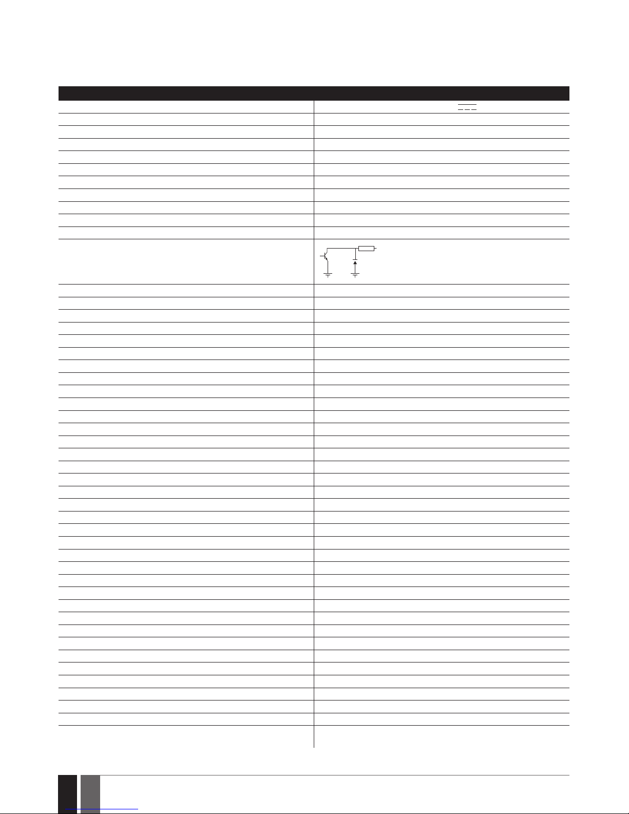
2.1. Electrical and Mechanical Characteristics
Electrical and Mechanical Characteristics
Power supply 16-24V 50/60 Hz ~1.5A max / 18-24V
1,5A max
Current consumption in idle state w/o external devices connected Up to 80mA
Recommended backup battery voltage, capacity 12V; 1,3-7Ah
Recommended backup battery type Lead-Acid
Backup battery charge current Up to 500mA
Backup battery charge duration Up to 30 hours for 7Ah battery
GSM modem frequency 850/900/1800/1900MHz
Cable type for GSM/GPRS antenna connection Shielded
Number of zones on-board 8 (ATZ mode: 16)
Nominal zone resistance 5,6k (ATZ Mode: 5,6k and 3,3k)
Number of PGM outputs on-board 4
On-board PGM output circuit
1 R
OUT
Open collector output.
Output is pulled to COM
when turned ON.
Maximum commuting on-board PGM output values (combined) 4 x 30V; 500mA
BELL: Siren output when activated Connected to COM
BELL: Maximum siren output current 1A
BELL: Maximum cable length for siren connection Up to 100m (328.08ft)
BELL: Cable type for siren connection Unshielded
AUX: Auxiliary equipment power supply voltage 13,8V DC
AUX: Maximum accumulative current of auxiliary equipment 1,1A
AUX: Maximum cable length for auxiliary equipment connection Up to 100m (328.08ft)
AUX: Cable type for auxiliary equipment connection Unshielded
BUZ: Maximum current of mini buzzer 150mA
BUZ: Power supply voltage of buzzer 12V DC
BUZ: Cable type for mini buzzer connection Unshielded
Supported temperature sensor model Maxim®/Dallas® DS18S20, DS18B20
Maximum supported number of temperature sensors 8
DATA: Maximum cable length for 1-Wire communication Up to 30m (98.43ft)
DATA: Cable type for 1-Wire communication Unshielded
Supported iButton key model Maxim®/Dallas® DS1990A
Maximum supported number of iButton keys 16
Maximum supported number of keypads 4 x EKB2 / EKB3
Y/G: Maximum cable length for RS485 communication Up to 100m (328.08ft)
Y/G: Cable type for RS485 communication Unshielded
MIC: Maximum cable length for microphone connection Up to 2m (6.56ft)
MIC: Cable type for microphone connection Unshielded
Wireless band ISM868
Wireless communication range Up to 3000m (9842.6ft) in open areas
Maximum supported number of wireless devices 32
Event log size 1024 events
Maximum supported number of zones 80
Maximum supported number of PGM outputs 48
Cable type for zone and PGM output connection Unshielded
Generated PSTN line values Voltage: 48V; current: 25mA; impedance: 270
Communications SMS, Voice calls, GPRS network, CSD, PSTN, Ethernet via ELAN3-ALARM
Supported protocols Ademco Contact ID, EGR100, Kronos, Cortex SMS, SIA IP
Dimensions 140x100x18mm (5.51x3.94x0.71in)
Operating temperature range -20...+55°C (-4... +131°F)
Humidity 0-90% RH @ 0... +40°C (0-90% RH @ +32... +104°F)
(non-condensing)
Page 17
17
17
EN
ESIM384 Installation and Conguration Manual v1.1
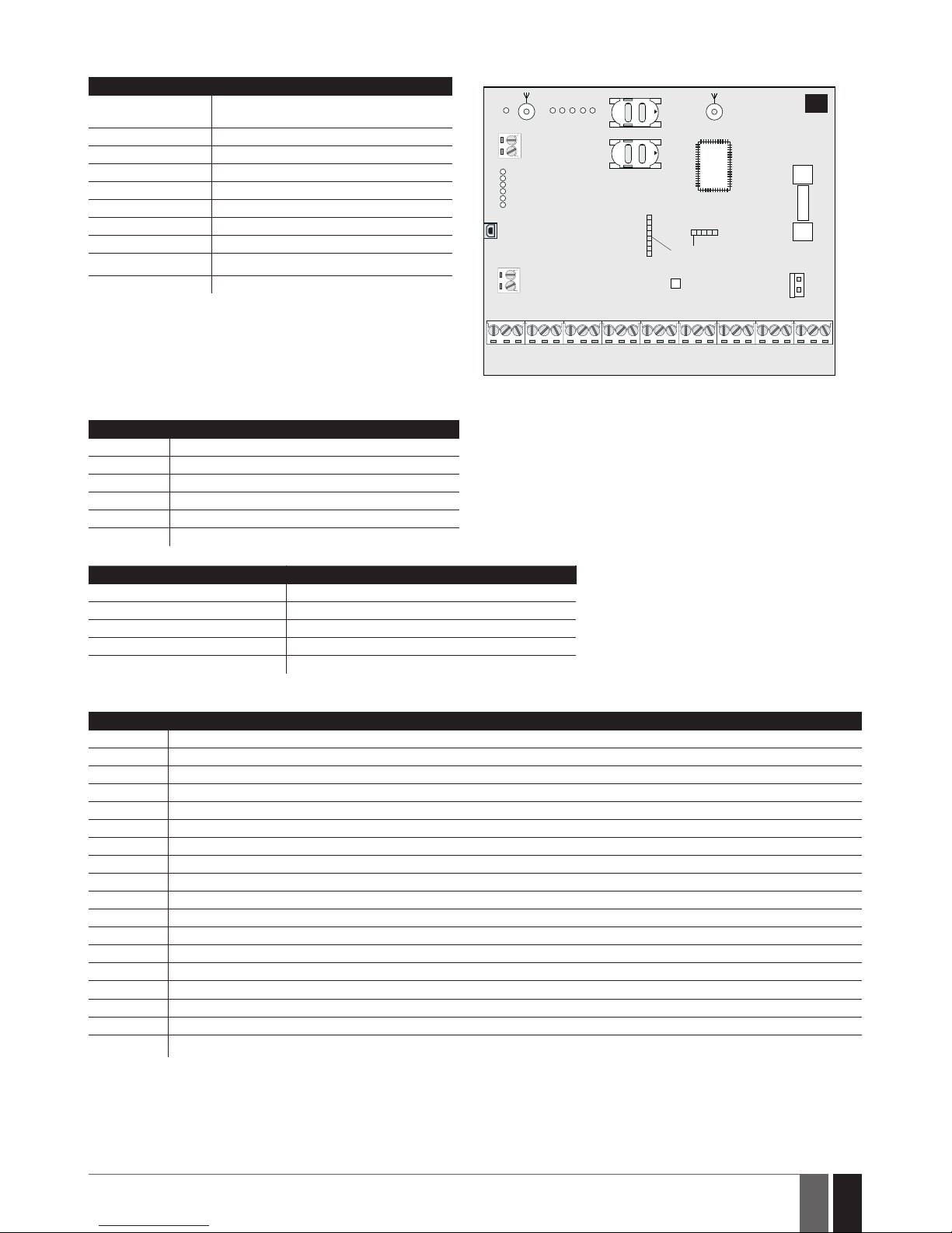
2.2. Main Unit, LED Indicator and Connector Functionality
Main Unit Functionality
GSM MODEM GSM network 850/900/1800/1900MHz
modem
SIM CARD1 Primary SIM card slot / holder
SIM CARD2 Secondary SIM card slot / holder
DEF Pins for restoring default settings
USB Mini USB port
FUSE F1 2A fuse
W-LESS ANT Wireless antenna SMA type connector
MIC Microphone connector
GSM/GPRS ANT GSM/GPRS antenna SMA type connector
MODULES* Slots for EA1, EA2 or EPGM8 module
ANTW-LESS
GSM/GPRS ANT
TIP
FUSE F1
RING
DEF
SIM CARD1
SIM CARD2
PRG
USB
AK U+
AK U-
C 2
C 3
C 3
C 4
C 4
C 1
S TA T
NE T W
2A
MODULES
MIC
OPENOPEN
BELL-
BELL+
GYC2
AUX-
AUX+
AC /D C
AC /D C
Z1
C O MZ2Z3
C O M
Z4
DA TA
+5V
BU Z-C1BU Z+
C O M
C O M
C O M
Z6
Z7
Z8
Z5
GSM
MODEM
1
LED Functionality
NETW GSM network signal strength
C1 PGM output C1 status - ON/OFF
C2 PGM output C2 status - ON/OFF
C3 PGM output C3 status - ON/OFF
C4 PGM output C4 status - ON/OFF
STAT Micro-controller status
NETW indication GSM signal strength
OFF No GSM signal
Flashing every 3 sec. Poor
Flashing every 1 sec. Medium
Flashing several times per sec. Good
Steady ON Excellent
Connector Functionality
TIP* PSTN (landline) terminal
RING* PSTN (landline) terminal
DATA 1-Wire interface for iButton key and temperature sensor connection
+5V Temperature sensor power supply terminal (+5V)
BUZ- Buzzer negative terminal
BUZ+ Buzzer positive terminal
C1 - C4 PGM output terminals
Z1 - Z8 Security zone terminals
Y RS485 interface CLOCK terminal (yellow wire)
G RS485 interface DATA terminal (green wire)
COM Common return terminal
BELL- Siren negative terminal (Commutated)
BELL+ Siren positive terminal (Constant voltage)
AU X- Negative power supply terminal for auxiliary equipment
AUX+ Positive power supply terminal for auxiliary equipment
AC/DC Main power supply terminals
AKU- Backup battery negative terminal
AKU+ Backup battery positive terminal
* - Optional, implementable on request in advance
Page 18
18
18
EN
ESIM384 Installation and Conguration Manual v1.1
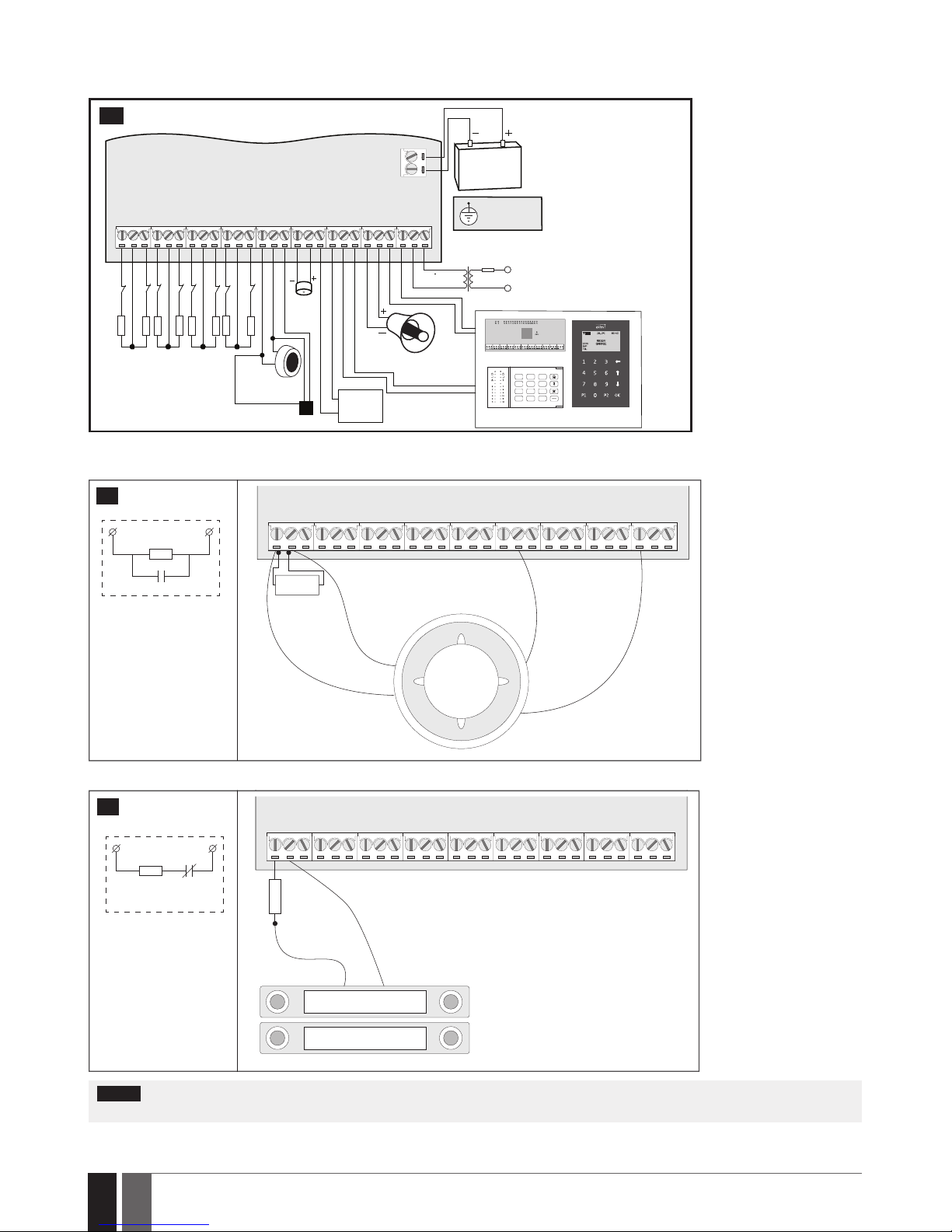
2.3. Wiring Diagrams
2.3.1. General Wiring
BELL-
BELL+
GYC2
AUX-
AUX+
AC /DC
AC /DC
Z1
C O M
Z2
Z3
C O M
Z4
+5V
BUZ -
C1
BUZ +
C O M
C O M
DAT A
C O M
Z6Z7Z8
Z5
BUZ
SIREN/BELL
iButton®
key reader
Temperature sensor
EKB2EKB3
EPGM1
Z1
Z2
Backup Battery
12V 1.3-7Ah
Metal cabinet
PE terminal
Relay
module
1A max.
Z4Z3Z5
Z6
Fuse 500 mA
~230V 50/60Hz
~16-24V
AKU +
AKU -
5,6 kΩ
5,6 kΩ
Z7
Z8
5,6 kΩ
5,6 kΩ
5,6 kΩ
5,6 kΩ
5,6 kΩ
5,6 kΩ
1 2 3
4 5 6
7 8 9
*
0 #
2
2.3.2. Zone Connection Types
Type 1 Example of 4-wire smoke detector wiring
Z1
COM
AUX+
+Vin
GND
C1
COM
NO
5,6 kΩ
3
8-Zone mode: Normally open contact
with 5,6K end-ofline resistor.
Z COM
NO
EOL 5.6K
Z COM
NC
EOL 5.6K
Z COM
NC
NC
5.6K
3.3K
Z COM
NC
3.3K
EOL 5.6K
TAMPER
Z COM
NC
3.3K
NC
5.6K
EOL 5.6K
TAMPER
Type 2 Example of magnetic door contact wiring
COM
NC
Magnet
COM
Z1
5,6 kΩ
Z COM
NC
EOL 5.6K
Z COM
NC
NC
5.6K
3.3K
Z COM
NC
3.3K
EOL 5.6K
TAMPER
Z COM
NC
3.3K
NC
5.6K
EOL 5.6K
TAMPER
8-Zone mode: Normally closed contact
with 5,6K end-ofline resistor
4
NOTE: Based on the example given, in the event of an alarm, the smoke detector could be reset by turning OFF and ON the PGM output
C1. For more details, please refer to 18.4. Turning PGM Outputs ON and OFF.
Page 19
19
19
EN
ESIM384 Installation and Conguration Manual v1.1
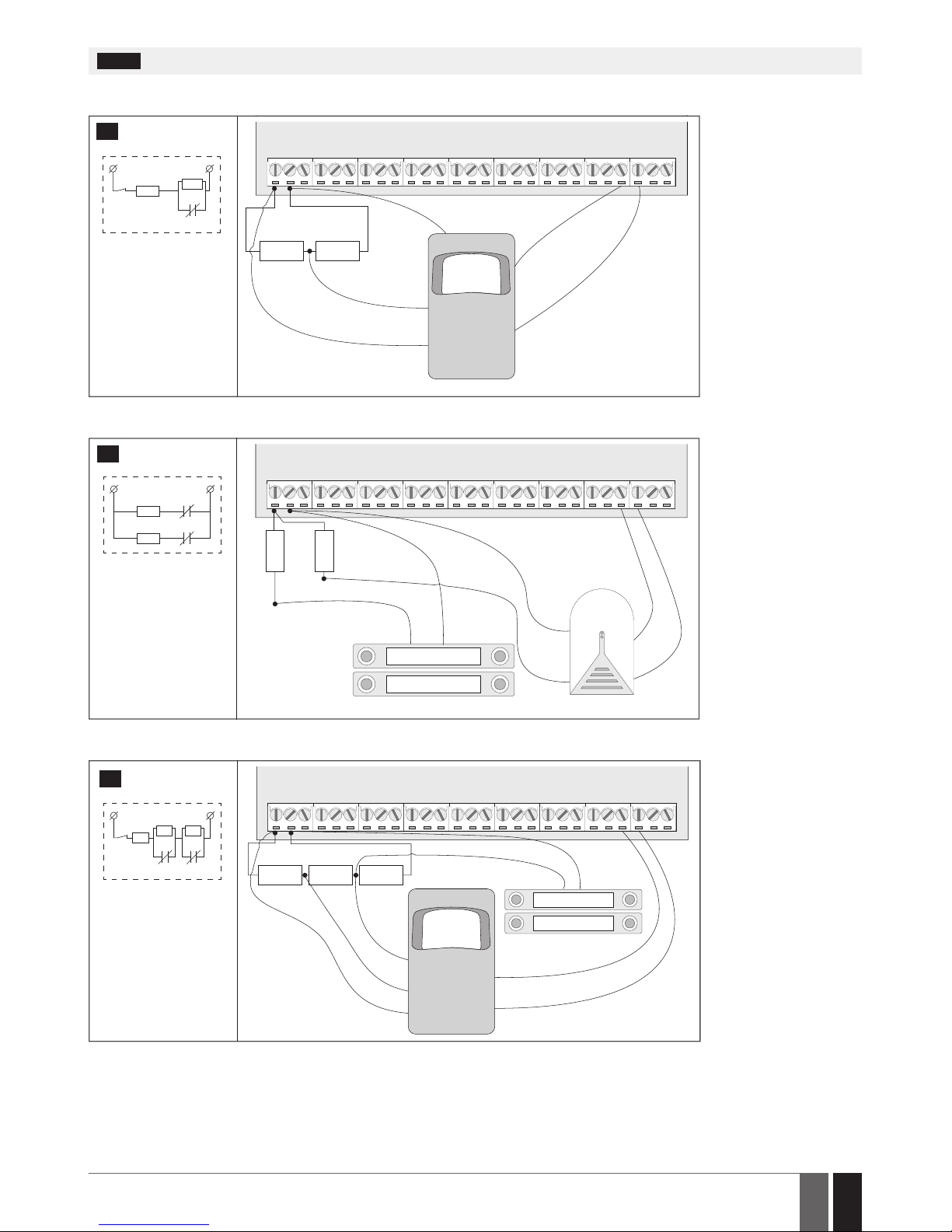
NOTE: The system does NOT support 2-wire smoke detectors.
Type 3 Example of motion detector wiring
Z1
COM
COM
AUX+
AU X-
+Vin
GND
NC
TAMP
5,6 kΩ 3,3 kΩ
Z COM
NC
NC
5.6K
3.3K
Z COM
NC
3.3K
EOL 5.6K
TAMPER
Z COM
NC
3.3K
NC
5.6K
EOL 5.6K
TAMPER
5
8-Zone mode: Tamper
and 5,6K end-of-line
resistor and 3,3K
end-of-line resistor
with normally closed
contact.
Type 4 Example of magnetic door contact (Z1) and glass break sensor (Z9) wiring
AUX+
+Vin
AU X-
GND
COM
COM
NC
NC
COM
Z1
5,6 kΩ
3,3 kΩ
Magnet
Z COM
NC
NC
5.6K
3.3K
Z COM
NC
3.3K
NC
5.6K
EOL 5.6K
TAMPER
6
ATZ mode: 5,6K
end-of-line resistor
and normally closed
contact with 3,3K
end-of-line resistor
and normally closed
contact
Type 5 Example of motion detector (Z1) and magnetic door contact (Z9) wiring
Z COM
NC
3.3K
NC
5.6K
EOL 5.6K
TAMPER
Z1
COM
COM
COM
AUX+
AU X-
+Vin
GND
NC
NC
TAMP
5,6 kΩ5,6 kΩ 3,3 kΩ
Magnet
ATZ mode: Tamper,
5,6K end-of-line
resistor, 5,6K
end-of-line resistor
with normally closed
contact and 3,3K
end-of-line resistor
with normally closed
contact.
7
See also 14.3. 8-Zone Mode and 14.4. ATZ (Advanced Technology Zone) Mode.
Page 20
20
20
EN
ESIM384 Installation and Conguration Manual v1.1
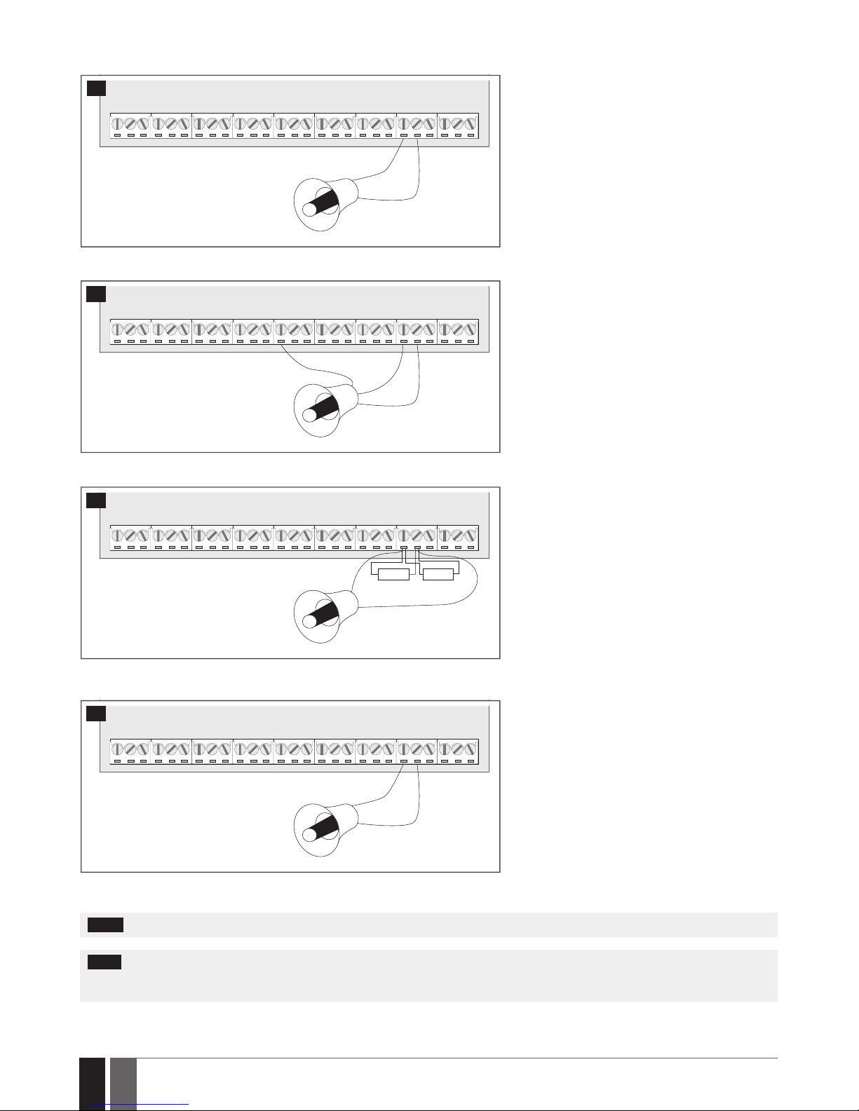
2.3.3. Siren
RED +
BLACK -
BELL-
BELL+
SIREN/BELL
1A max.
8
Piezo siren
1 Connect positive siren wire (red) to BELL+ ter-
minal.
2 Connect negative siren wire (black) to BELL-
terminal.
+12V
GND
BELL
BELL-
COM
BELL+
SIREN/BELL
1A max.
9
Self-contained siren
1 Connect negative GND siren wire to COM termi-
nal.
2 Controlling BELL siren wire must be connected
to BELL- terminal.
3 Connect positive +12V siren wire to BELL+ ter-
minal.
RED +
BLACK -
BELL-
BELL+
SIREN/BELL
1A max.
3,3kΩ 3,3kΩ
10
Siren status monitoring
NOTE: Siren status monitoring feature supervises
the resistance across BELL+ and BELL- terminals.
The resistance must be ranging from 1k through
3,3k, otherwise the system will indicate system
fault. In order to view the siren resistance value,
please refer to Diagnostic Management feature
available on ELDES Conguration software.
RED +
BLACK -
BELL-
BELL+
SIREN/BELL
1A max.
11
No siren status monitoring
If the siren status monitoring feature is not required, do not connect any resistor in parallel and
disable siren fault indication on the keypad (see 29.
INDICATION OF SYSTEM FAULTS).
See also 20. SIREN/BELL.
NOTE: BELL- is the commuted terminal intended for siren control.
NOTE: Siren status monitoring feature supervises the resistance across BELL+ and BELL- terminals. The resistance must be ranging from
1k through 3,3k, otherwise the system will indicate system fault. In order to view the siren resistance value, please refer to Diagnostic
Management feature available on ELDES Conguration software.
Page 21
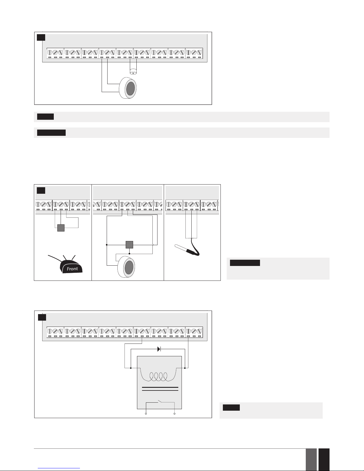
21
21
EN
ESIM384 Installation and Conguration Manual v1.1
2.3.4. iButton Key Reader and Buzzer
BUZ-
BUZ+
+-
COM
DATA
BUZZER
brown
white
iButton
key reader
12
Supported iButton key model: Maxim/Dallas
DS1990A
The iButton key reader can be installed with buzzer
or separately. The buzzer is intended for audio indication of exit/entry delay countdown providing
short beeps.
1 Connect iButton key reader brown and white
wires to 1-Wire interface: COM and DATA terminals respectively.
2 Connect buzzer‘s negative terminal wire to BUZ-
and positive terminal wire to BUZ+.
NOTE: The installation of buzzer is not necessary if EKB2/EKB3 keypad is used.
ATENTION: The cable length for connection to 1-Wire interface can be up to 30m (98.43ft) max.
2.3.5. Temperature Sensor and iButton Key Reader
Supported iButton key model: Maxim/Dallas DS1990A
Supported temperature sensor model: Maxim/Dallas DS18S20, DS18B20
COM
DATA
+5V
GND
DATA
+5V
iButton
key reader
DS1990A
Temperature
sensor
DS18S20
white
brown
COM
DATA
+5V
GND +5V
DATA
Temperature sensor
DS18S20
GND D ATA +5V
COM
DATA
+5V
black
yellow
red
Digital thermometer
with 3m (9.84ft) wire
Vinson DS18B20
13
1 Depending on the model, connect temper-
ature sensor GND/black wire, DATA/yellow
wire, +5V/red wire terminals to 1-Wire interface: COM, D ATA and +5V terminals respectively.
2 When connecting iButton key reader in par-
allel to temperature sensor, connect iButton
key rea der terminal wires to COM and DATA
terminals respectively.
ATENTION: The cable length for connec-
tion to 1-Wire interface can be up to 30m
(98.43ft) max.
2.3.6. Relay Finder (for example, model 40.61.9.12) with Terminal Socket (for example, model 95.85.3) to PGM Output
Example of relay wiring for negative PGM output control
A1
C1
AUX+
A2
COIL
RELAY
14
1 Wire up relay A1 terminal to PGM output Cx and
A2 terminal to AUX+.
2 In addition, connect the switching diode to re-
lay‘s A2 and A1 terminals.
NOTE: We highly recommend using switch-
ing diode model 1N4148 or similar.
Page 22
22
22
EN
ESIM384 Installation and Conguration Manual v1.1
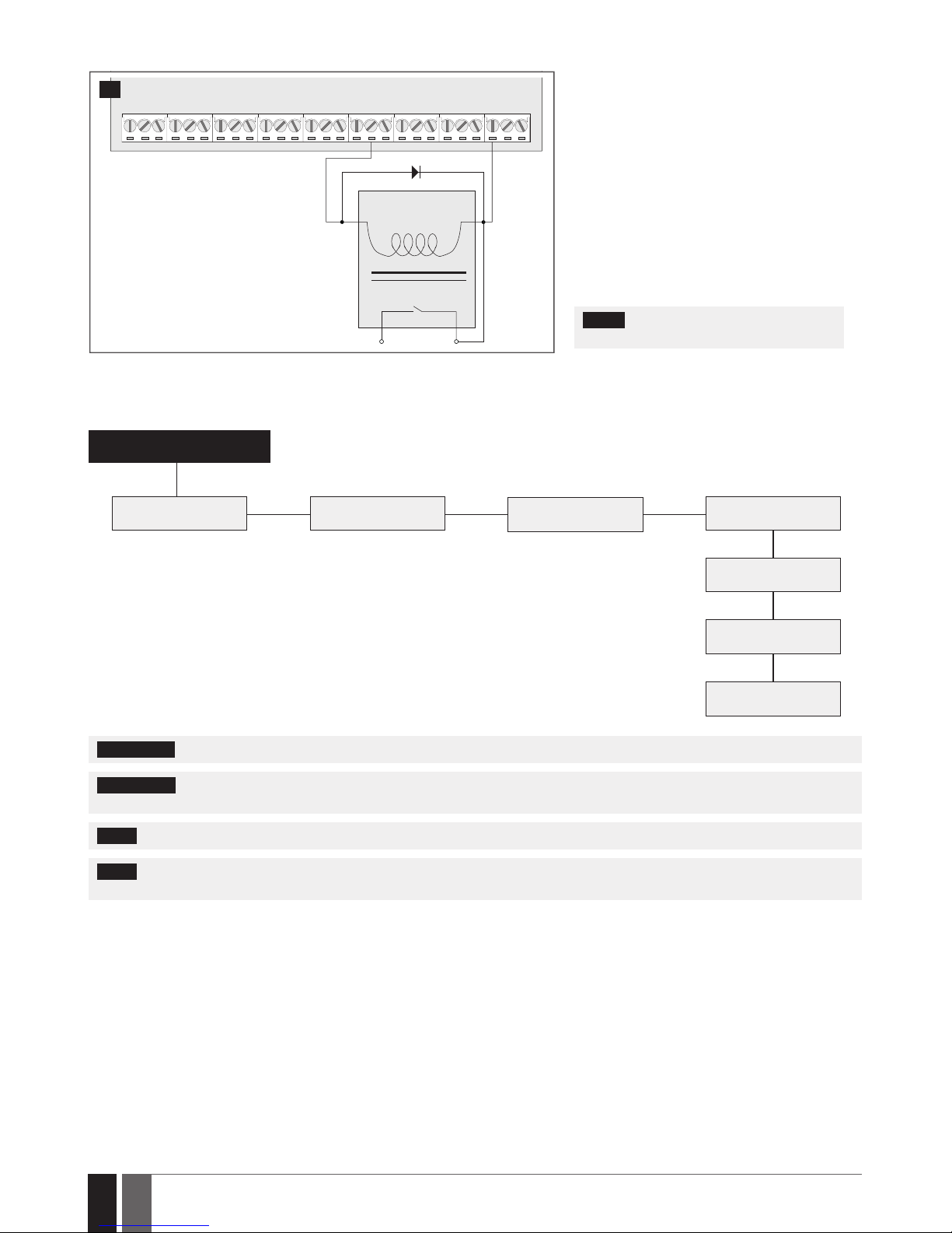
Example of relay wiring for positive PGM output control
A1
C1
AUX+
A2
COIL
RELAY
15
1 Wire up relay A1 terminal to PGM output‘s Cx
terminal and A2 terminal to AUX+ and one of
the relay‘s switch contacts: NC or NO.
2 In addition, connect the switching diode to re-
lay‘s A2 and A1 terminals.
NOTE: We highly recommend using switch-
ing diode model 1N4148 or similar.
2.3.7. RS485
Serial Wiring Method
ESIM384
a
b c
d
e
f
g
EKB2/EKB3 EKB2/EKB3
EKB2/EKB3
EKB2/EKB3
EPGM1
EPGM1
ELAN3-ALARM
Max. cable length: a+b+c+d+e+f+g= up to 100m (328.08ft)
ATTENTION: The cable length must not exceed 100m (328.08ft) in total.
ATTENTION: When wiring more than 1 keypad and/or EPGM1 module, please ensure that the set address of each keypad and/or EPGM1
module is dierent.
NOTE: If necessary, the RS485 devices can be powered from an external 12-14V DC power supply instead of AUX+ and AUX- terminals
NOTE: You may connect only 1 EKB2/EKB3 keypad or a mixed combination of EKB2 and EKB3 keypads. The combination can consist of
up to 4 keypads in total.
For more details on RS485 interface, please refer to 32.1. RS485 Interface
Page 23
23
23
EN
ESIM384 Installation and Conguration Manual v1.1
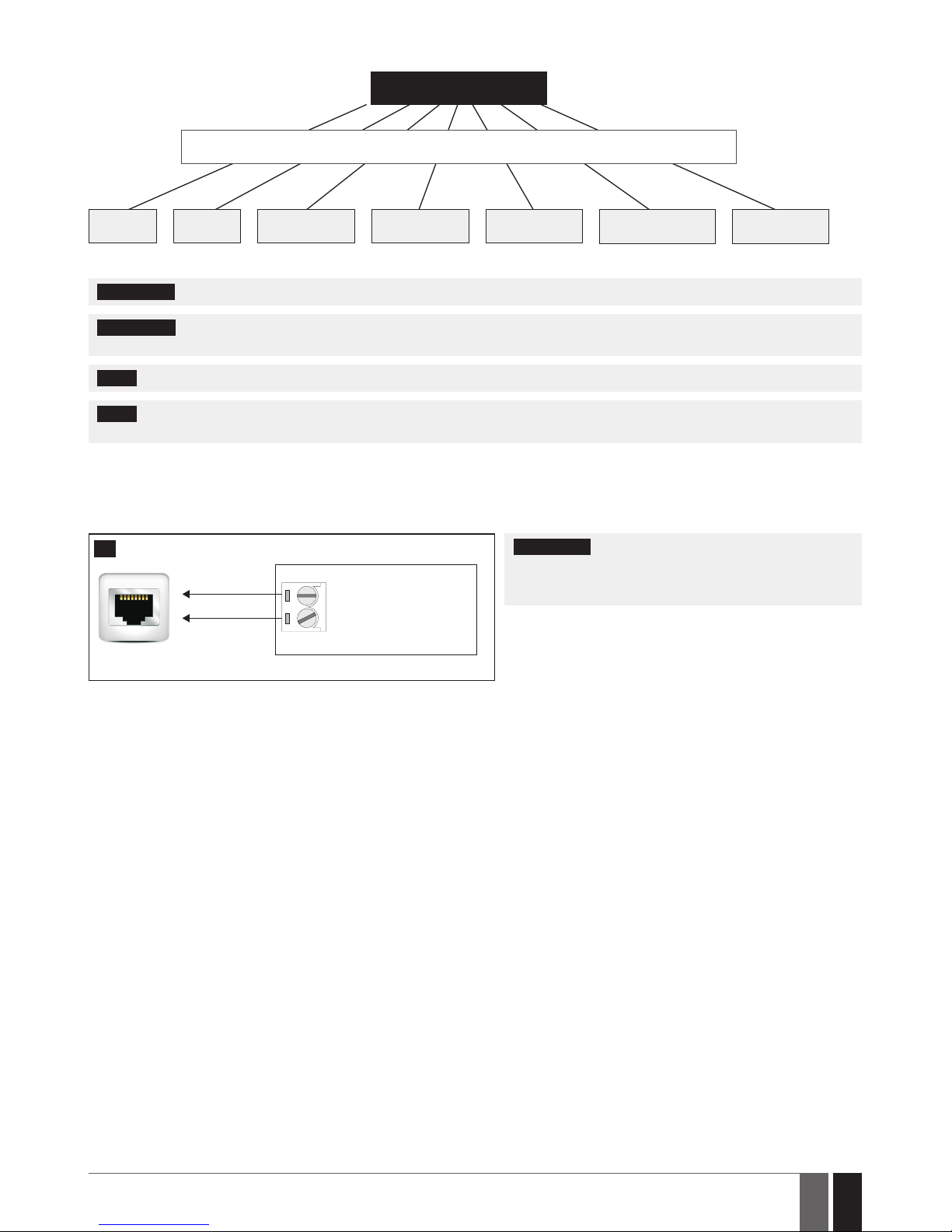
Parallel Wiring Method
ESIM384
Max. cable length: up to 100m (328.08ft)
EPGM1 EPGM1 EKB2/EKB3 EKB2/EKB3 EKB2/EKB3
ELAN3-ALARM EKB2/EKB3
ATTENTION: The cable between ESIM384 and each RS485 device must be of the same length and can NOT exceed 100m (328.08ft).
ATTENTION: When wiring more than 1 keypad and/or EPGM1 module, please ensure that the set address of each keypad and/or EPGM1
module is dierent.
NOTE: If necessary, the RS485 devices can be powered from an external 12-14V DC power supply instead of AUX+ and AUX- terminals
NOTE: You may connect only 1 EKB2/EKB3 keypad or a mixed combination of EKB2 and EKB3 keypads. The combination can consist of
up to 4 keypads in total.
For more details on RS485 interface, please refer to 32.1. RS485 Interface
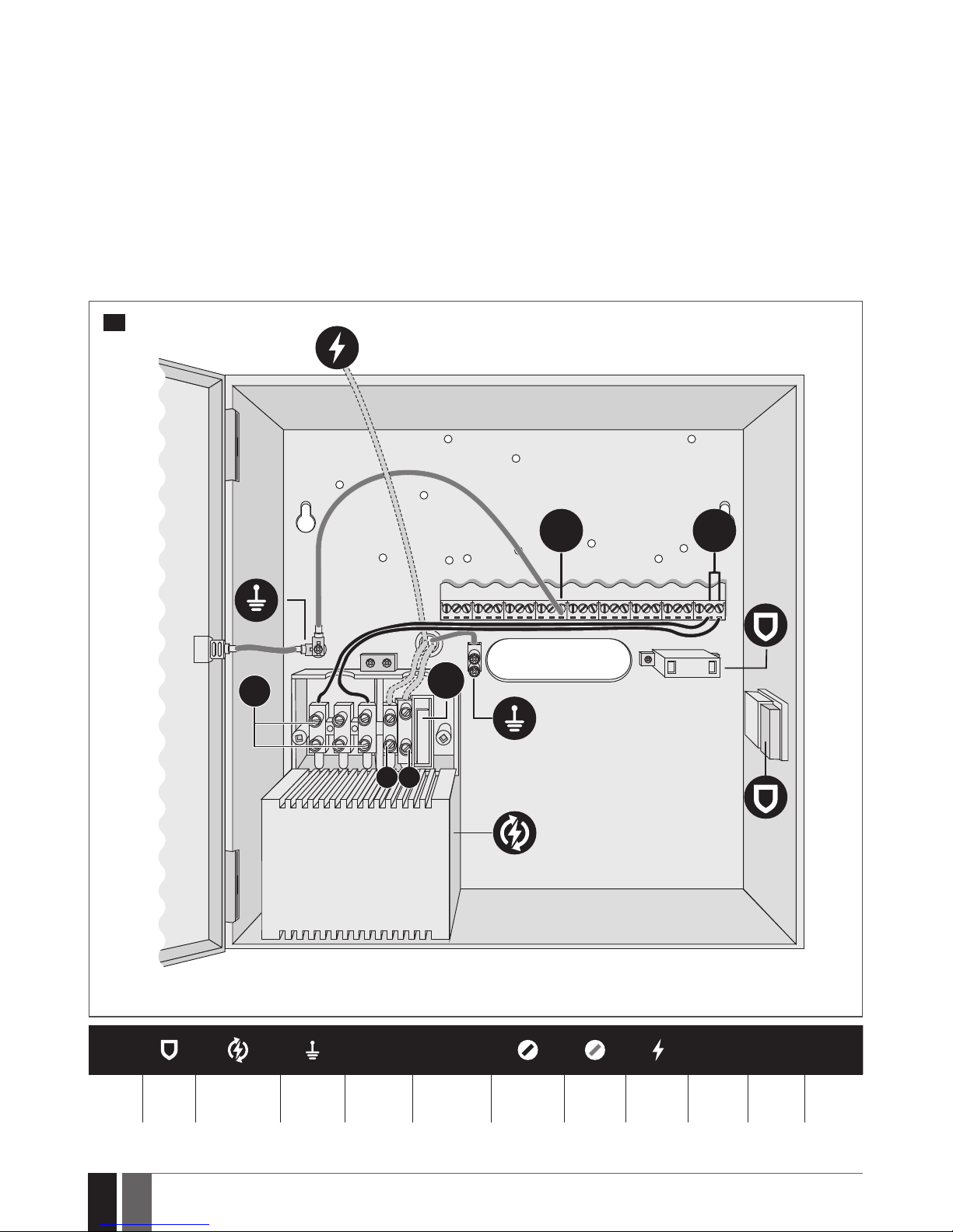
2.3.8. RING/TIP
RING
TIP
ESIM384
to PSTN
(landline)
16
ATTENTION: The TIP/RING connectors and PSTN module
are NOT included in a standard ESIM384 alarm system unit.
These components are op tional and can be implemented on
request in advance.
Page 24
24
24
EN
ESIM384 Installation and Conguration Manual v1.1
3. INSTALLATION
When professional installation, OEM integration or assembly by a third-party is expected, the installation instructions and assembly requirements approved for equipment approval must be provided to the integrators to clearly identify the specic requirements necessary
to maintain RF exposure compliance. The grantee of a transmitter, typically the manufacturer, is responsible for ensuring installers and
integrators have a clear understanding of the compliance requirements by including the required instructions and documentation with
the product and, if necessary, to provide further support to full grantee responsibilities for ensuring compliance. The integrators must
be fully informed of their obligations and verify the resolution of any issues and concerns with each transmitter manufacturer or grantee.
• The system can be installed in a metal or non-ammable cabinet only. For a convenient installation, ME1 metal cabinet is highly recommended. The metal cabinet must always be grounded as well as ESIM384 system’s PCB by connecting one of the COM terminals to the
PE contact of the metal cabinet.
• For the connection of 230V transformer, use 3x0.75 mm2 1 thread double isolated cable. 230V power supply cables must not be
grouped with low voltage cable group.
• For the connection of auxiliary and BELL outputs, use 2x0.75 mm2 1 thread unshielded cable of up to 100m (328.08ft) length.
• For the connection of zone/PGM output connectors, use 0.50 mm2 1 thread unshielded cable of up to 100m (328.08ft) length.
SYSTEM INSTALLATION IN ME1 METAL CABINET AND ENCLOSURE COMPONENTS
TRANSFORMER
AC/DC
COM
FUSE
N L
18V
AC230V
17
FUSE COM AC/DC
18V N L
Fuse
315mA
Tamper Transformer
PE
terminal
Common
terminal
Main power
supply
terminal
AC/DC Main
power
wire
GND wire
230V
wire
AC
voltage
Null Phase
Page 25
25
25
EN
ESIM384 Installation and Conguration Manual v1.1
ELAN3ALARM
TRANSFORMER
TRANSFORMER
18
ESIM384 + EPGM1
TRANSFORMER
OPENOPEN
TRANSFORMER
19
Page 26
26
26
EN
ESIM384 Installation and Conguration Manual v1.1
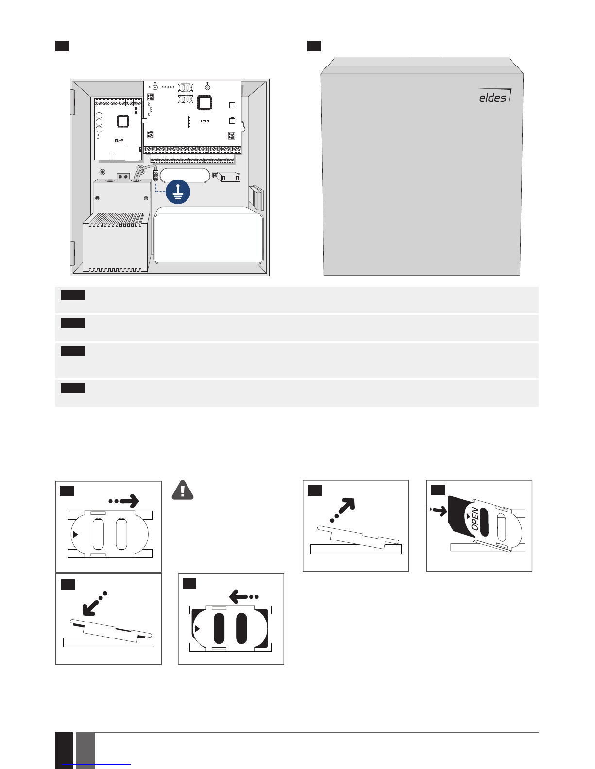
ME1 METAL CABINET CONTAINING ALL COMPONENTS
OPENOPEN
12 V BATTERY
TRANSFORMER
20 21
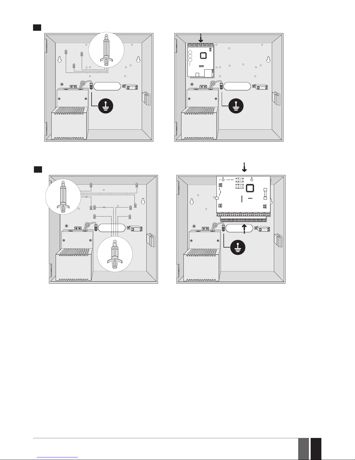
NOTE: The standard ME1 metal cabinet does NOT contain all of plastic standos, the quantity and the type of which depends on your addi-
tionally acquired device.
NOTE: Insert the plastic standos into the appropriate mounting points and x the circuit board of selected device on the holders as indicated
above (in pics on page 25).
NOTE: In order to appropriately install EPGM1 module, please install it in the rst place and ESIM384 alarm system afterwards. EPGM1 must
be mounted on shorter plastic standos, while ESIM384 and ELAN3-ALARM – on the longer ones. The mounting points of EPGM1 module and
ESIM384 system are indicated in pics on page 25.
NOTE: You also may wire up the accessories, such as keypads, zone and PGM output expansion modules, ELAN3-ALARM module, tempera-
ture sensors. If you choose to install the buzzer, it must be closer to iButton key reader in order to hear the exit delay countdown.
1. Disable the PIN code of the SIM card by inserting it into a mobile phone and following the proper menu steps. Ensure that the addition-
al services, such as voice mail, call forwarding, report on missed/busy calls (“call catcher”) are disabled on the SIM card. For
more details on how to disable these services, please contact your GSM operator.
2. Once the PIN code is disabled, place the SIM card into the SIM CARD1 slot of the alarm system. If Dual-SIM feature is to be used, insert
another SIM card into the SIM CARD2 slot. For more details, please refer to 31. DUAL-SIM MANAGEMENT.
Inserting a SIM card into SIM
CARD1 slot is mandatory as it is
the main SIM card slot, while using a SIM card in SIM CARD2 slot is
optional.
OPEN
22
23
24
25
OPEN
26
Page 27
27
27
EN
ESIM384 Installation and Conguration Manual v1.1
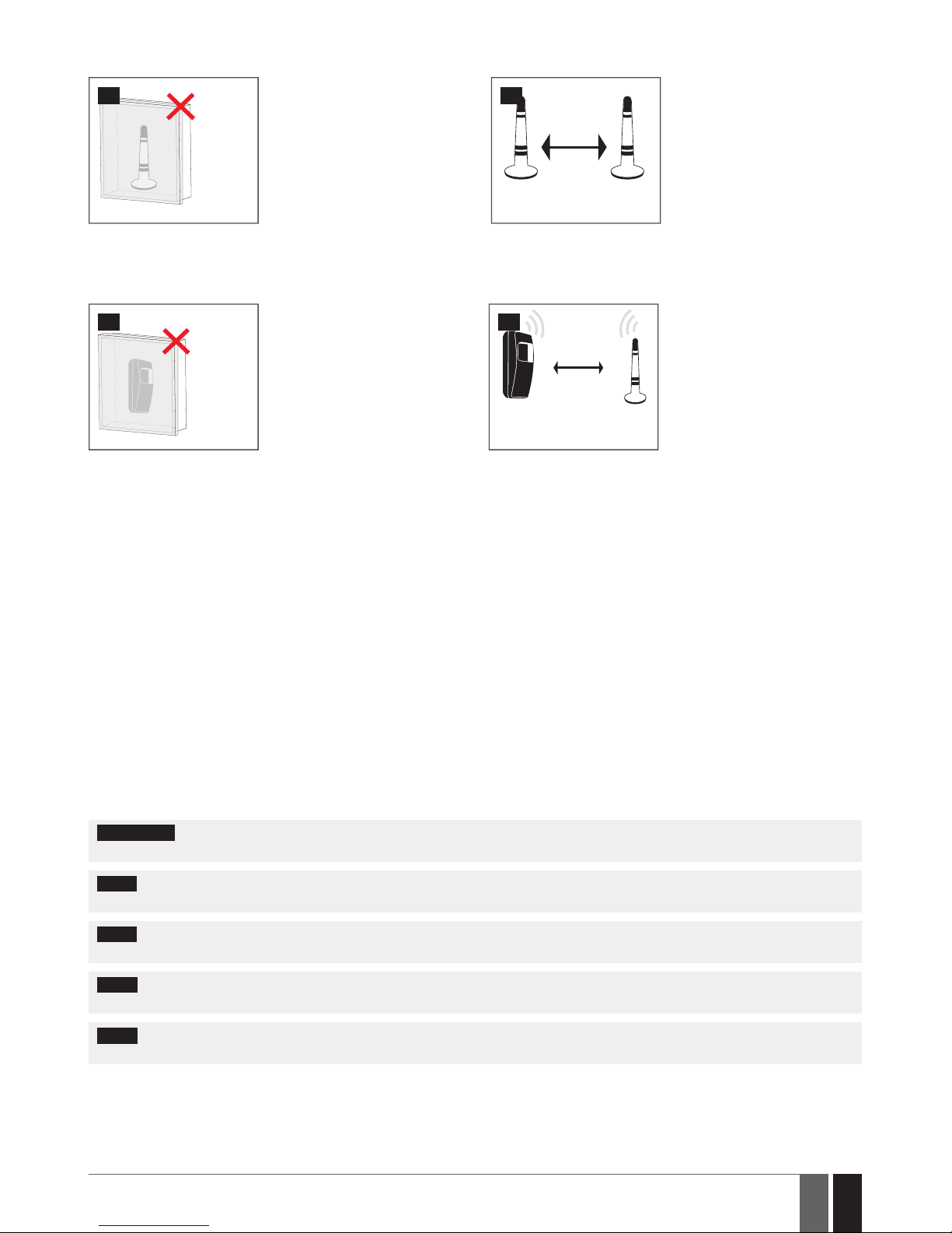
3. Connect the GSM/GPRS and wireless antennas and follow the recommendations for the installation:
GSM/
GPRS
and/or
wireless
antenna
27
Never install in the following
locations:
• inside the metal cabinet
• closer than 20cm (7.87in) from
the metal surface and/or power
lines
GSM/GPRS
antenna
20cm (7.87in)
or more
Wireless
antenna
28
Recommended installation:
• keep the distance of at least
20cm (7.87in) or more.
4. If one or more wireless devices are to be paired, follow the recommendations for the installation to achieve the strongest wireless
signal:
Wireless
device
29
Never install in the following
locations:
• inside the metal cabinet
• closer than 20cm (7.87in) from
the metal surface and/or power
lines
Wireless
device
Wireless
antenna
0.5 m to 30 m
(1.64 to 98.43ft)
inside the building
0.5 m to 150 m
(1.64 to 492.13ft)
in open areas
30
Recommended installation:
• face the front side of the
wireless device towards the
antenna
• keep the distance: 0,5 to 30m
(1.64 to 98.43ft) inside the
building, 0,5 to 3000m (1.64 to
9842.6ft) in open areas
For more details on how to install the wireless devices, please refer to chapter 41.RADIO SYSTEM INSTALLATION AND SIGNAL PENE-
TRATION manual and the latest user manual of the wireless device located at www.eldesalarms.com
5. Power up the system and wait until indicator STAT lights up (see 2.2 Main Unit, LED Indicator and Connector Functionality).
6. Indicator STAT should be ashing indicating successful micro-controller operation.
7. The illuminated indicator NETW indicates that the system successfully registered to GSM network. To nd the strongest GSM signal,
place the GSM/GPRS antenna and follow the indications provided by NETW indicator (see 2.2 Main Unit, LED Indicator and Connec-
tor Functionality).
8. Change the default SMS password (see 6. SMS PASSWORD AND INSTALLER CODE for more details).
9. Set the phone number for User 1 (see 8. USER PHONE NUMBERS for more details).
10. Set system date and time (see 9. DATE AND TIME for more details).
11. Once the system is fully congured, it is ready for use. However, if you fail to receive an SMS reply from the system, please check the
SMSC (Short Message Service Center) phone number. For more details regarding the SMS centre phone number, please refer to 27.1.
SMSC (Short Message Service Center) Phone Number.
12. If it is required to change the batteries for the wireless devices or carry out other system maintenance tasks, please activate the Ser-
vice mode. For more detail regarding this mode, please refer to 33. SERVICE MODE.
ATTENTION: The system is NOT compatible with pure 3G SIM cards. Only 2G/GSM SIM cards and 3G SIM cards with 2G/GSM prole enabled
are supported. For more details, please contact your GSM operator.
NOTE: The installation of iButton key reader, EKB2/EKB3/EKB3W/EWKB4 keypad, EWK2 wireless keyfob is not mandatory. However, it
is recommended to have those devices installed as an emergency switch in case your mobile phone is switched o or missing.
NOTE: For maximum system reliability we recommend you do NOT use a Pay As You Go SIM card. Otherwise, in the event of insucient
credit balance on the SIM card, the system would fail to make a phone call or send messages.
NOTE: We advise you to choose the same GSM SIM provider for your system as for your mobile phone. This will ensure the fastest, most
reliable SMS text message delivery service and phone call connection.
NOTE: Even though alarm system ESIM384 installation process is not too complicated, we still recommend to perform it by a person
with basic knowledge in electrical engineering and electronics to avoid any system damage.
Page 28

28
28
EN
ESIM384 Installation and Conguration Manual v1.1
4. GENERAL OPERATIONAL DESCRIPTION
When the system is being armed, it will initiate the exit delay countdown intended for the user to leave the secured area. During the countdown period the buzzer will emit short beeps. By default, exit delay duration is 15 seconds. After the countdown is complete, the system
will become armed and lock the conguration by keypad possibility. In case the user does not leave the secured area before the countdown
is complete, the system will STAY-arm if at least 1 zone has Stay attribute enabled. By default, if there is at least 1 violated zone or tamper,
the user will not be able to arm the system until the violated zone or tamper is restored. In case it is required to arm the alarm system
despite the violated zone presence, the violated zone can be bypassed or Force attribute enabled. After the system is armed and if a zone
(depending on type) or tamper is violated, the system will cause an alarm lasting for 1 minute (by default), During the alarm, the siren/bell
will provide an alarm sound along with the buzzers of the keypads. By default, the system will also makes a phone call and send an SMS text
message containing the violated zone or tamper number to a listed user phone number and indicate the violated zone or tamper number
on the keypad. If another zone or tamper is violated or the same one is restored and violated again during the alarm, the system will act as
mentioned previously, but will not extend the alarm time.
After the user enters the secured area, the system will initiate the entry delay countdown intended for system disarming. During the countdown period, the buzzer will emit a steady beep. By default, entry delay duration is 15 seconds. After the user successfully performs the
disarming process, the system will unlock the keypads. If the user does not disarm the system in time, the alarm system will cause an
instant alarm.
NOTE: The alarm will be caused even if a tamper is violated while the system is disarmed.
For more details, please refer to 12. ARMING AND DISARMING.
Page 29
29
29
EN
ESIM384 Installation and Conguration Manual v1.1
5. CONFIGURATION METHODS
!!! In this installation manual the underscore character ”_” represents one space character. Every underscore character must
be replaced by a single space character. There must be no spaces or other unnecessary characters at the beginning and at
the end of the SMS text message.
5.1. SMS Text Messages
SMS
In order to congure and control the system by SMS text message, send the text command to the ESIM384 system phone
number from one of the listed user phone numbers. The structure of SMS text message consists of 4-digit SMS password
(the default SMS password is 0000 – four zeros), the parameter and value. For some parameters the value does not apply e. g.
STATUS. The variables are indicated in lower-case letters, while a valid parameter value range is indicated in brackets.
NOTE: By default the SMS password is 0000, which is necessary to change.
5.2. EKB2 LCD Keypad
EKB2
The system conguration and control by EKB2 keypad is carried out by navigating throughout the menu section list displayed
on LCD screen. To navigate in the menu path, touch ↓, ↑ keys to select the desired menu section and touch OK key to open the
selected section. To enter a required value, use 0... 9 keys and touch OK key for conrmation or cancel/go one menu section
back by touching ← key. The value can be typed in directly by touching 0... 9 keys while highlighting the desired menu section.
EKB2 menu type is “circle”, therefore when the last section in the menu list is selected, you will be brought back to the beginning of the list after touching the ↓ key. In this installation manual, the menu path is based on the EKB2 menu tree by starting
at home screen view (see 32.1.1.2. Master and User Menu Tree and 32.1.1.3. Installer Menu Tree). The variables are
provided in lower-case letters, while a valid parameter value range is provided in brackets.
Activate
Conguration mode
EKB2
Menu path:
OK → iiii → OK
Value: iiii - 4-digit installer code.
Deactivate
Conguration mode
EKB2
Return to home screen view
NOTE: By default, menu section CONFIGURATION is secured with installer code. The default installer code is 1470, while the default master
code is 1111.
NOTE: The system can be congured using only one keypad at a time. Other connected keypads will be inactive while the menu section
CONFIGURATION is opened. The inactive EKB2 keypads will display
icon.
NOTE: The keypad will automatically exit the menu section CONFIGURATION and return to home screen view if 1 minute after the last
key-touch expires.
Page 30
30
30
EN
ESIM384 Installation and Conguration Manual v1.1
5.3. EKB3/EKB3W/EWKB4 LED Keypads
EKB3/
EKB3W/
EWKB4
The system conguration and control by EKB3/EKB3W/EWKB4 keypad is carried out by activating the Conguration mode
using the installer code (by default – installer code is 1470) and entering a valid conguration command using the number
keys
0
9
, key for conrmation and * key to clear the characters that have been typed. Alternatively, the user
can wait for 10 seconds until the keypad buzzer will provide a long beep indicating that the entered characters have been
cleared. When typing in the characters, the indication of each pressed key is provided by short beep of keypad buzzer and
red indicators when the number keys
0
9
are being pressed. Some commands require , , and keys as
well. The structure of a standard conguration command is a combination of digits. The commands, which do not require the
Conguration mode being activated, are noted. The variables are provided in lower-case letters, while a valid parameter value
range is provided in brackets.
NOTE: If you have accidentally typed in an unnecessary character, please press * key or wait for 10 seconds until the keypad buzzer will
provide a long beep indicating that the typed in characters have been cleared.
NOTE for EKB3W/EWKB4: Even if Back-light Timeout has expired, the character will be considered as typed in once the appropriate EK-
B3W/EWKB4 key is pressed. For more details, please refer to 19.5.3. Wireless Communication, Sleep Mode and Back-light Timeout.
EN50131-1
GRADE 3
Activate
Conguration mode
EKB3/
EKB3W
Enter installer and master codes:
iiiiii mmmmmm #
Value: iiiiii – 6-digit installer code; mmmmmm - 6-digit master code.
Example:
147000111111#
EN50131-1
GRADE 3
Deactivate
Conguration mode
EKB3/
EKB3W
Enter installer code:
iiiiii #
Value: iiiiii – 6-digit installer code.
Example:
147000#
The following table provides a list of EKB3/EKB3W/EWKB4 indications, which are relevant during Conguration mode.
Indication Description
Indicator
ashing
Conguration mode activated successfully.
Indicator
ashing
Valid parameter entered and awaiting for valid value to be entered.
1 long beep Non-existing command or invalid parameter value entered.
3 short beeps Command entered successfully.
NOTE: The default installer code is 1470, while the default master code is 1111. By activating 6-digit password/code format, it will be neces-
sary to extend the installer code, master code and user code by adding 2 extra digits using ELDES Conguration software.
NOTE: The system can be congured using only one keypad at a time. Other connected keypads will be inactive while the Conguration
mode is activated.
5.4. ELDES Conguration software
ELDES
Cong-
uration
Software
ELDES Conguration software is intended for ESIM384 alarm system conguration locally via USB port or remotely via GPRS
network or Ethernet connection (ELAN3-ALARM device required). This software simplies system conguration process by
allowing to use a personal computer in the process. Before starting to use ELDES Conguration software, please read the user
guide provided in the software’s documentation.
5.4.1. Remote Connection
ATTENTION: The system will NOT transmit any data to monitoring station while conguring the system remotely via GPRS network or
Ethernet connection. However, during the remote connection session, the data messages are queued up and transmitted to the monitoring station after the conguration session is over.
ATTENTION: When the Conguration mode is activated by EKB3/EKB3W/EWKB4 keypad or when menu section CONFIGURATION is
opened by the installer using EKB2 keypad, remote system conguration is disabled.
ATTENTION: The keypad (-s) become inactive while the system is being congured remotely.
ELDES Conguration software provides remote system conguration ability via Internet using one of the following methods:
• ELDES proxy server (recommended). The connection can be established on the system via GPRS network or Ethernet using ELAN3ALARM communicator.
Page 31
31
31
EN
ESIM384 Installation and Conguration Manual v1.1
• Running TCP/IP server on ELDES Conguration software (advanced). The connection can be established on the system via GPRS
network or Ethernet using ELAN3-ALARM communicator.
• Direct connection via Ethernet using ELAN3-ALARM communicator.
In order to start using the remote conguration feature, please run the step-by-step wizard and follow the steps provided in the start page
of ELDES Conguration software. Please, note that based on the selected method, it might be necessary to send an SMS text message to
the system’s phone number in order to initiate the remote connection. By following the steps you will be instructed on what text must be
sent to the system’s phone number in such case.
5.4.2. Ending the Remote Connection Session
After the remote system conguration is complete, use one of the following methods to end the conguration process:
• Click Disconnect or Stop button and close ELDES Conguration software.
• The session will automatically expire in 20 minutes. Before the last 5 minutes, the software will oer the user to extend the session for
another 20 minutes.
• Alternatively, the connection with the server can be terminated at any time by sending an SMS text message.
Terminate the
connection with server
SMS
SMS text message content:
ssss_ENDCONFIG
Value: ssss – 4-digit SMS password.
Example: 1111_ENDCONFIG
Once the session is expired or terminated, the system will reply with an SMS text message conrming the end of the session.
5.5. System conguration by USB cable
In order to congure the system by USB cable, the user must plug the specied cable into personal computer’s USB port and launch the
pre-installed ELDES Conguration software. Conguration by USB cable and ELDES Conguration software does not require the external
power supply to be connected to the device. However, the device will NOT fully function when USB-powered .The user will be able to carry
out some major part of system’s conguration, with the exception of those functions, which are strictly related to GSM modem (disabled
during the selected conguration period) or associated with the Wireless connectivity (also disabled).
Page 32
32
32
EN
ESIM384 Installation and Conguration Manual v1.1
6. SMS PASSWORD AND INSTALLER CODE
For security reasons, the system uses the following type of password and code:
SMS password – 4-digit password used for system arming/disarming and conguration by SMS text messages. By default, SMS password is
0000, which MUST be changed!. SMS password is authorized to carry out the following:
• Access system conguration by SMS text messages.
• Arm/disarm partition.
• Activate/deactivate service mode.
• Set system date and time.
• Add/remove user phone numbers.
• Set SMS password.
• Turn ON/OFF PGM outputs.
• Restart system remotely.
Installer code – 4-digit password used for system conguration by EKB2/EKB3/EKB3W/EWKB4 keypad and ELDES Conguration soft-
ware. By default, installer code is 1470, which is highly recommended to change. Installer code is authorized to carry out the following:
• Access system conguration by keypad and ELDES Conguration software.
• Set installer code.
• Set master code.
• Activate/deactivate service mode.
• Set system date and time.
• Add/remove user phone numbers.
• Set SMS password.
• Restore system conguration to default.
• Clear tamper fault (if enabled).
Set SMS password
SMS
SMS text message content:
wwww_PSW_ssss
Value: wwww – 4-digit existing SMS password; ssss – 4-digit new SMS password; range –
[0001... 9999].
Example: 0000_PSW_1111
EKB2
Menu path:
OK → iiii → OK → PRIMARY SETTINGS → OK → SMS PASSWORD → OK → ssss → OK
Value: iiii – 4-digit installer code; ssss – 4-digit new SMS password; range – [0001... 9999].
EKB3/
EKB3W/
EWKB4
Enter parameter 14 and new SMS password:
14 ssss #
Value: ssss – 4-digit new SMS password; range – [0001... 9999].
Example: 141111#
Cong
Tool
This operation may be carried out from the PC using the ELDES Conguration software.
Set installer code
EKB2
Menu path:
OK → 1470 → OK → PRIMARY SETTINGS → OK → INSTALLER CODE → OK → iiii → OK
Value: iii – 4-digit new installer code; range – [0000... 9999].
EKB3/
EKB3W/
EWKB4
Enter parameter 16 and new installer code:
16 iiii #
Value: iiii – 4-digit new installer code; range – [0000... 9999].
Example: 162538#
Cong
Tool
This operation may be carried out from the PC using the ELDES Conguration software.
Page 33

33
33
EN
ESIM384 Installation and Conguration Manual v1.1
7. SYSTEM LANGUAGE
The system comes equipped with a single language for communication with the user by SMS text messages and EKB2 keypad menu display.
The system language depends on ESIM384 rmware, which is based on the user’s location.
List of currently available system languages (rmwares):
•Czech
•English
•Estonian
•Finnish
•French
•German
•Greek
•Hungarian
•Italian
•Latvian
•Lithuanian
•Polish
•Portuguese
•Romanian
•Russian
•Slovak
•Spanish
NOTE: To obtain a rmware that features a dierent SMS and EKB2 menu language, please contact your local dealer.
Page 34
34
34
EN
ESIM384 Installation and Conguration Manual v1.1
8. USER PHONE NUMBERS
The system supports up to 10 user phone numbers identied as User 1 through 10. When the phone number is set, the user will be able to
arm/disarm the system by SMS text messages and free of charge phone calls (see 12.1. Free of Charge Phone Call and 12.2. SMS Text
Message) as well as to congure the system by SMS text messages. User phone numbers are also used to receive alarm phone calls via
GSM connection and SMS text messages from the system (see 17. ALARM INDICATIONS AND NOTIFICATIONS FOR USER).
By default, the system accepts incoming calls and SMS text messages from any phone number. Once a user phone number is listed, the
system ignores any incoming calls and SMS text messages from a non-listed phone number as well as it rejects the SMS text messages
containing wrong SMS password even from a listed user phone number (see 8.2. System Control from any Phone Number).
To set User 1 phone number is mandatory, while the other 9 are optional. The supported phone number formats are the following:
• International (with plus) – The phone numbers must be entered starting with plus and an international country code in the fol-
lowing format: +[international code][area code][local number], example for UK: +44170911XXXX1. This format can be used when
setting up the phone number by SMS text message and ELDES Conguration software.
• International (with 00) – The phone numbers must be entered starting with 00 and an international country code in the following
format: 00[international code][area code][local number], example for UK: 0044170911XXXX1. This format can be used when setting up the phone number by SMS text message, EKB2/EKB3/EKB3W/EWKB4 keypad and ELDES Conguration software.
• Local – The phone numbers must be entered starting with an area code in the following format: [area code][local number], example
for UK: 0170911XXXX1. This format can be used when setting up the phone number by SMS text message, EKB2/ EKB3/EKB3W/
EWKB4 keypad and ELDES Conguration software.
Add user phone
number
SMS
SMS text message content:
ssss_NRup:ttteeellnnuumm
Value: ssss – 4-digit SMS password; up – user phone number slot, range – [1... 10]; ttteeelln-
nuumm – up to 15 digits user phone number.
Example: 1111_NR1:+44170911XXXX1
EKB2
Menu path:
OK → iiii → OK → PRIMARY SETTINGS → OK → CALL/SMS SETTINGS → OK → USERS → OK →
GSM USER 1... 10 → OK → PHONE NUMBER → OK → ttteeellnnuumm → OK
Value: iiii – 4-digit installer code; ttteeellnnuumm – up to 15 digits user phone number.
EKB3/
EKB3W/
EWKB4
Enter parameter 17, user phone number slot and phone number:
17 up ttteeellnnuumm #
Value: up – user phone number slot, range – [01... 10]; ttteeellnnuumm – up to 15 digits user
phone number.
Example: 17010044170911XXXX1#
ELDES
Cong-
uration
soft-
ware
This operation may be carried out from the PC using the ELDES Conguration software.
View user phone
number
SMS
SMS text message content:
ssss_HELPNR
Value: ssss – 4-digit SMS password.
Example: 1111_HELPNR
EKB2
Menu path:
OK → iiii → OK → PRIMARY SETTINGS → OK → CALL/SMS SETTINGS → OK → USERS → OK →
GSM USER 1... 10 → OK → PHONE NUMBER
Value: iiii – 4-digit installer code;
ELDES
Conguration
software
This operation may be carried out from the PC using the ELDES Conguration software.
Page 35
35
35
EN
ESIM384 Installation and Conguration Manual v1.1
Delete user phone
number
SMS
SMS text message content:
ssss_NRup:DEL
Value: ssss – 4-digit SMS password; up – user phone number slot, range – [2... 10].
Example: 1111_NR2:DEL
EKB2
Menu path:
OK → iiii → OK → PRIMARY SETTINGS → OK → CALL/SMS SETTINGS → OK → USERS → OK →
GSM USER 2... 10 → OK → PHONE NUMBER → OK → OK
Value: iiii – 4-digit installer code;
ELDES
Cong-
uration
software
This operation may be carried out from the PC using the ELDES Conguration software.
ATTENTION: NEVER add a phone number of the device’s SIM card as a user phone number!
ATTENTION: Once User 1 phone number is set, it will be restricted to modify it only.
NOTE: Multiple user phone numbers can be set by a single SMS text message,
Example: 1111_NR1:+44170911XXXX1_ NR2:+44170911XXXX2_NR6:0170911XXXX3_NR10:+44170911XXXX4
NOTE: Multiple user phone numbers can be deleted by a single SMS text message, Example: 1111_NR2:DEL_NR3:DEL_NR6:DEL_NR9:DEL_
NR:10:DEL
8.1. User Phone Number Names
When the system is armed or disarmed by free of charge phone call or SMS text message, the system sends a conrmation by SMS text message to user phone number that the system arming/disarming was initiated from. The SMS text message is sent regarding each partition
separately and contains system status and partition name as well as it may contain a user name, set to the user phone number.
Manage user phone
number name
ELDES
Conguration
software
This operation may be carried out from the PC using the ELDES Conguration software.
8.2. System Control from any Phone Number
By default, once a user phone number is listed, the system ignores any incoming calls and SMS text messages from a non-listed phone
number as well as it rejects the SMS text messages containing wrong SMS password even from a listed user phone number. To permit/deny
system arming/disarming by phone call and SMS text message that contain a valid SMS password, conguration by SMS text message that
contain a valid SMS password from any phone number, please refer to the following conguration methods.
Enable system control
from any phone
number
SMS
SMS text message content:
ssss_STR:ON
Value: ssss – 4-digit SMS password.
Example: 1111_STR:ON
EKB2
Menu path:
OK → iiii → OK → PRIMARY SETTINGS → OK → CALL/SMS SETTINGS → OK → CTRL FROM ANY
NUM → OK → ENABLE → OK
Value: iiii – 4-digit installer code;
EKB3/
EKB3W/
EWKB4
Enter parameter 12 and parameter status value:
12 1 #
Example: 121#
ELDES
Conguration
software
This operation may be carried out from the PC using the ELDES Conguration software.
ATTENTION: Due to security reasons it is HIGHLY UNRECOMMENDED to enable this feature.
Page 36
36
36
EN
ESIM384 Installation and Conguration Manual v1.1
Disable system
control from any
phone number
SMS
SMS text message content:
ssss_STR:OFF
Value: ssss – 4-digit SMS password.
Example: 1111_STR:OFF
EKB2
Menu path:
OK → iiii → OK → PRIMARY SETTINGS → OK → CALL/SMS SETTINGS → OK → CTRL FROM ANY
NUM → OK → DISABLE → OK
Value: iiii – 4-digit installer code;
EKB3/
EKB3W/
EWKB4
Enter parameter 12 and parameter status value:
12 0 #
Example: 120#
ELDES
Conguration
software
This operation may be carried out from the PC using the ELDES Conguration software.
9. DATE AND TIME
The system comes equipped with internal real-time clock (RTC) that keeps track of the current date and time. Once the system is up and
running, the user must set the correct date and time, otherwise the system will not operate properly. By default, after shutting down and
starting up the system, the date and time must be set again.
Set date and time
SMS
SMS text message content:
ssss_yyyy.mt.dd_hr:mn
Value: ssss – 4-digit SMS password; yyyy – year; mt – month, range – [01... 12]; dd – day, range
– [01... 31]; hr – hours, range – [00... 23]; mn – minutes, range – [00... 59].
Example: 1111_2014.03.16_14:33
EKB2
Menu path:
a) OK → uumm → OK → DATE/TIME SETTINGS → OK → yyyy-mt-dd hr:mn → OK
b) OK → iiii → OK → PRIMARY SETTINGS → OK → DATE/TIME SETTINGS → OK → yyyy-mt-dd
hr:mn → OK
Value: uumm – 4-digit user/master code; yyyy – year; mt – month, range – [01... 12]; dd – day,
range – [01... 31]; hr – hours, range – [00... 23]; mn – minutes, range – [00... 59]; iiii – 4-digit
installer code.
EKB3/
EKB3W/
EWKB4
Enter parameter 66, date and time:
66 yyyy mt dd hr mn#
Value: yyyy – year; mt – month, range – [01... 12]; dd – day, range – [01... 31]; hr – hours, range
– [00... 23]; mn – minutes, range – [00... 59].
Example: 66201405291235#
ELDES
Conguration
software
This operation may be carried out from the PC using the ELDES Conguration software.
ATTENTION! To set date and time using EKB3/EKB3W/EWKB4 command, described above, you MUST enter the Conguration mode rst!
ELDES Conguration software provides the ability to select the Time Zone option. The user may also choose Get PC Time option, which
instantly provides the exact PC time.
NOTE: When the system is connected to the monitoring station via IP connection (see 30. MONITORING STATION) and/or when ELDES
Cloud Services feature is in use (see 36. ELDES CLOUD SERVICES), the date and time will be automatically synchronized with the monitoring
station or ELDES Cloud Services server upon the system startup. However, SIA IP data format users must enable time synchronization feature
using ELDES Conguration software.
9.1. Automatic Date and Time Synchronization
This feature enables the system to set the date and time automatically without the user being involved in this process. The system supports the following methods of automatic date and time synchronization that are used automatically on system start-up and periodically
(by default – every 30 days):
Page 37
37
37
EN
ESIM384 Installation and Conguration Manual v1.1
• Via GSM network – Once enabled, the system automatically sends a date/time request to the GSM operator. This method is the
most accurate synchronization method. Some GSM operators might not support it.
• By SMS text message – Once enabled, the system automatically sends the SMS text message to its own phone number and re-
trieves the date and time from the SMS text message reply, as the included date and time is set by the SMSC (SMS center). This
method is not as accurate as the synchronization via GSM network, but always eective.
By default, synchronization via GSM network is disabled. To enable/disable automatic date and time synchronization via GSM network,
please refer to the following conguration methods.
Enable/disable
synchronization via
GSM network
ELDES
Conguration
software
This operation may be carried out from the PC using the ELDES Conguration software.
By default, synchronization by SMS text message is disabled. To enable/disable automatic date and time synchronization by SMS text message, please enter/remove device phone number using one of the following conguration methods.
Enter/remove device
phone number for
synchronization by
SMS text message
ELDES
Conguration
soft-
ware
This operation may be carried out from the PC using the ELDES Conguration software.
Page 38
38
38
EN
ESIM384 Installation and Conguration Manual v1.1
10. MASTER AND USER CODES
NOTE for EKB3/EKB3W/EWKB4: The Conguration mode must remain deactivated before accessing master and user code manage-
ment using the master code.
The system supports up to 30 numeric codes, identied as Master code and User code 2 through 30, allowing to carry out system arming/
disarming as well as minor system conguration and control by the keypad.
Master code is authorized to carry out the following:
• Arm/disarm partition.
• Bypass violated zones.
• View violated zones and tampers.
• View system faults.
• Set system date and time.
• View temperature sensor information.
• View event log,
• View and clear alarm log,
• Set/delete user codes.
• Turn ON/OFF PGM outputs.
• Assign an existing user code as Duress code.
• Assign an existing user code as SGS code.
User code is authorized to carry out the following:
• Arm/disarm partition.
• Bypass violated zones.
• View violated zones and tampers.
• View system faults.
• Set system date and time.
• View temperature sensor information.
• View and clear alarm log.
By default, only Master code is listed as 1111 and assigned Partition 1 ONLY. For more details regarding User/Master code partition, please
refer to 23.4. User/Master Code Partition.
Set master code
EKB2
Menu path:
a) OK → vvvv → OK → CODES→ OK → MASTER CODE → OK → CODE → OK → mmmm → OK
b) OK → iiii → OK → PRIMARY SETTINGS → OK → MASTER CODE → mmmm → OK
Value: vvvv – 4-digit existing master code, range – [0000... 9999]; iiii – 4-digit installer code;
mmmm – 4-digit new master code, range – [0000... 9999].
EKB3/
EKB3W/
EWKB4
a) Press , 0, enter existing master code and new master code:
0 vvvv 01 mmmm # mm #
Value: vvvv – 4-digit existing master code; mmmm - 4-digit new master code; range -
[0000... 9999].
Example:
01111012222#
b) (Only when Conguration Mode is activated);
Enter parameter 63, existing master code and new master code:
63 vvvv mmmm #
Value: vvvv – 4-digit existing master code; mmmm – 4-digit new master code, range –
[0000... 9999].
Example: 6311112222#
ELDES
Conguration
software
This operation may be carried out from the PC using the ELDES Conguration software.
Page 39
39
39
EN
ESIM384 Installation and Conguration Manual v1.1
Set user code
EKB2
Menu path:
User code 2... 16: OK → mmmm → OK → CODES → OK → USER CODE (2-16) → OK → USER CODE
2... 16 → OK → CODE → OK → uuuu → OK
User code 17... 30: OK → mmmm → OK → CODES → OK → USER CODE (17-30) → OK → USER
CODE 17... 30 → OK → CODE → OK → uuuu → OK
Value: mmmm – 4-digit master code; uuuu – 4-digit user code, range – [0000... 9999].
EKB3/
EKB3W/
EWKB4
Press , 0, enter master code, user code slot and user code:
0 mmmm us uuuuu #
Value: mmmm - 4-digit master code; us - user code slot, range - [02... 30]; uuuu - 4-digit user
code, range - [0000... 9999].
Example:
01111092556#
ELDES
Conguration
software
This operation may be carried out from the PC using the ELDES Conguration software.
Delete user code
EKB2
Menu path:
OK → mmmm → OK → CODES → OK → REMOVE CODE → OK → uuuu → OK
Value: mmmm – 4-digit master code; uuuu – 4-digit user code.
EKB3/
EKB3W/
EWKB4
Press , 0, enter master code and user code slot:
0 mmmm us #
Value: mmmm - 4-digit master code; us - user code slot, range - [02... 30].
Example:
0111109#
ELDES
Conguration
software
This operation may be carried out from the PC using the ELDES Conguration software.
NOTE: The system does not allow to set a duplicate code.
The user codes ranging from User code 2 through 10 can be set as SGS (Security Guard Service) code, which is used as a checkpoint by a
security service guard upon his/her visit in the secured location. When used, a data message, containing a certain event code, will be delivered to the monitoring station. However, NO system arming or disarming will be carried out after entering the SGS code.
Set SGS code
EKB2
Menu path:
OK → mmmm → OK → CODES → OK → SGS CODE → OK → N/A | USER CODE 2... 10 → OK
Value: mmmm – 4-digit master code; N/A – SGS code not in use.
EKB3/
EKB3W/
EWKB4
Press , 4, enter user code slot and enter master code:
4 us mmmm #
Value: us - user code slot, range - [02... 10]; mmmm - 4-digit master code.
Example:
4041111#
ELDES
Conguration
software
This operation may be carried out from the PC using the ELDES Conguration software.
The Duress code is used when system arming or disarming is demanded by force. When used, the system will arm/disarm as well as it will
silently transmit an alert to the monitoring station. Only one of the user codes ranging from User code 2 through 10 can be set as Duress code.
Set Duress code
EKB2
Menu path:
OK → mmmm → OK → CODES → OK → DURESS CODE → OK → N/A | USER CODE 2... 10 → OK
Value: mmmm – 4-digit master code; N/A – Duress code not in use.
EKB3/
EKB3W/
EWKB4
Press , 3, enter user code slot and master code:
3 us mmmm #
Value: us - user code slot, range - [02... 10]; mmmm - 4-digit master code.
Example:
3081111#
Page 40
40
40
EN
ESIM384 Installation and Conguration Manual v1.1
ELDES
Conguration
soft-
ware
This operation may be carried out from the PC using the ELDES Conguration software.
10.1. Master and User Code Names
When the system is armed or disarmed by entering a master or user code using a keypad, the system sends a conrmation by SMS text message to user phone number, sharing the same partition (-s) as the keypad and user/master code. The SMS text message is sent regarding
each partition separately and contains system status and partition name as well as it may contain a user name, set to the user/master code.
Manage user/master
code name
Cong
Tool
This operation may be carried out from the PC using the ELDES Conguration software.
Page 41
41
41
EN
ESIM384 Installation and Conguration Manual v1.1
11. IBUTTON KEYS
An iButton key is a unique 64-bit ID code containing chip enclosed in a stainless steel tab usually implemented in a small plastic holder.
ESIM384 system supports up to 16 iButton keys each holding a unique identity code (ID), which is used for system arming and disarming.
11.1. Adding and Removing iButton Keys
NOTE: iButton Key 1 can be added without Allow Adding New iButton Keys mode being enabled.
To add an iButton key to the system, do the following:
a) Disarm the system in all partitions (see 12. ARMING AND DISARMING).
b) Enable Allow Adding New iButton Keys mode.
c) Touch the key to the iButton key reader when the system is disarmed.
31
d) The successfully added iButton key will be indicated by short beeps emitted by the system’s buzzer.
e) Add as many iButton keys as necessary – touch one key after another to the reader – until the number of 16 keys is reached.
Enable Allow Adding
New iButton Keys
mode
SMS
SMS text message content:
ssss_IBPROG:ON
Value: ssss – 4-digit SMS password.
Example: 1111_IBPROG:ON
EKB2
Menu path:
OK → iiii → OK → IBUTTON KEYS → OK → NEW IBUTTON → OK → ENABLE → OK
Value: iiii - 4-digit installer code.
EKB3/
EKB3W/
EWKB4
Enter parameter 18 and parameter status value:
18 0 #
Example: 180#
ELDES
Cong-
uration
software
This operation may be carried out from the PC using the ELDES Conguration software.
When adding of iButton keys is complete, please disable Allow Adding New iButton Keys mode.
Page 42
42
42
EN
ESIM384 Installation and Conguration Manual v1.1
Disable Allow Adding
New iButton Keys
mode
SMS
SMS text message content:
ssss_IBPROG:OFF
Value: ssss – 4-digit SMS password.
Example: 1111_IBPROG:ON
EKB2
Menu path:
OK → iiii → OK → IBUTTON KEYS → OK → NEW IBUTTON → OK → DISABLE → OK
Value: iiii - 4-digit installer code.
EKB3/
EKB3W/
EWKB4
Enter parameter 18 and parameter status value:
18 1 #
Example: 181#
ELDES
Cong-
uration
software
This operation may be carried out from the PC using the ELDES Conguration software.
To view the ID of the added iButton keys, please refer to the following conguration methods.
View iButton key ID
EKB2
Menu path:
OK → iiii → OK → IBUTTON KEYS → OK → IBUTTON → OK → IBUTTON 1...16 → OK → ID
Value: iiii - 4-digit installer code.
ELDES
Conguration
software
This operation may be carried out from the PC using the ELDES Conguration software.
If the iButton key is lost or stolen, due to security reasons it is highly recommended to remove it from the system.
Remove individual
iButton key from the
system
EKB2
Menu path:
OK → iiii → OK → IBUTTON KEYS → OK → IBUTTON → OK → IBUTTON 1...16 → OK →
REMOVE → OK
Value: iiii - 4-digit installer code.
ELDES
Conguration
software
This operation may be carried out from the PC using the ELDES Conguration software.
Remove all iButton
keys from the system
SMS
SMS text message content:
ssss_RESETIB
Value: ssss – 4-digit SMS password.
Example: 1111_RESETIB
11.2. iButton Key Names
When the system is armed or disarmed by iButton key, the system sends a conrmation by SMS text message to listed user phone number,
sharing the same partition (-s) as the key. The SMS text message is sent regarding each partition separately and contains system status and
partition name as well as it may contain a user name, set to the iButton key.
Manage iButton key
name
ELDES
Conguration
soft-
ware
This operation may be carried out from the PC using the ELDES Conguration software.
Page 43

43
43
EN
ESIM384 Installation and Conguration Manual v1.1
12. ARMING AND DISARMING
The system features the following methods to carry out arming and disarming process:
• Free of charge phone call
• SMS text message
• EKB2/EKB3/EKB3W/EWKB4 keypad, EWKB5 touchpad and user/master code
• iButton key
• EWK1/EWK2/EWK2A wireless keyfob
• Arm-Disarm by Zone
• EGR100 middle-ware
• Automatic arm/disarm by scheduler
• ELDES Cloud Services platform
The system partitions can be armed/disarmed by the listed user phone number, EKB2/EKB3/EKB3W/EWKB4 keypad and user/master code,
iButton key, EWK1/EWK2/EWK2A wireless keyfob, automatically according to the scheduled weekday and time or zone, which is set up for
Arm-Disarm by Zone method. For example, if User 1 phone number is assigned to Partition 1, 2 and 4, the user will be able to arm/disarm
Partition 1, 2 and 4 by a single phone call to the system (see 23. PARTITIONS).
By default, when the system is successfully armed or disarmed, it replies with conrmation by SMS text message. For more details on SMS
text message regarding system arming/disarming and how to manage it, please refer to 12.10. Disabling and Enabling Arm/Disarm
Notications.
By default, it is allowed to arm the system while the following system faults are present (see 29. INDICATION OF SYSTEM FAULTS):
• Mains power is lost.
• Low battery.
• Battery dead or missing.
• Battery failed.
• Siren failed.
• Date/time not set.
• GSM connection failed.
• GSM/GPRS antenna failed.
• Wireless antenna failed.
• Keypad lost.
• Wireless power socket (EWM1) fault.
• Wireless device battery low.
• Communication to MS failed.
• RF jammer detected.
In case of violated zone/tamper presence when attempting to arm the system by free of charge phone call, SMS text message, iButton key
and Arm-Disarm by Zone method, the system will reply with SMS text message containing violated zone/tamper number. Due to security
reasons it is highly recommended to restore the violated zone/tamper before arming the system. For more details on how to arm the system regardless of the violated zone or tamper presence, please refer to 14.6. Zone Attributes, 14.7. Bypassing and Activating Zones
and 16.TAMPERS respectively.
The system ignores any incoming calls and SMS text messages from a non-listed phone number as well as it rejects the SMS text messages
containing wrong SMS password even from a listed user phone number. For more details regarding arming/disarming the system from a
non-listed phone number, please refer to 8.2. System Control from any Phone Number.
NOTE: The system remembers the last status (armed/disarmed) of all partitions even after complete shut down.
Page 44
44
44
EN
ESIM384 Installation and Conguration Manual v1.1
12.1. Free of Charge Phone Call
To arm, disarm the system and turn OFF the alarm, dial the system‘s phone number from any of 10 available user phone numbers
(see 8. USER PHONE NUMBERS for user phone number management). The phone call is free charge as the system rejects it
and carries out arming/disarming procedure afterwards. When arming – the system rejects the phone call after 2 rings, when
disarming – the system rejects the phone call immediately. If there is more than one listed user dialling to the system at the
same time, the sys tem will accept the incoming call from the user who was the rst to dial while other user (-s) will be ignored.
When system’s phone number is dialled for arming, the system will proceed as follows:
• Non-partitioned system:
• If ready (no violated zone/tamper), the system will arm.
• If unready (violated zone/tamper is present), the system will not arm and provide a list of violated zones/tampers by SMS text
message to user phone number. In such case the user must restore all violated zones and tampers before arming the system.
Alternatively, the violated zones can be bypassed (see 14.7. Bypassing and Activating Zones), disabled (see 14.9. Disabling
and Enabling Zones) or a Force attribute enabled (resulting in partial arm; see 14.6. Zone Attributes), while the tampers can
be disabled (see 16. TAMPERS).
• Partitioned system:
• If all partitions are disarmed ready, the system will arm them.
• If one or more partitions are disarmed unready (violated zone/tamper is present), the system will arm the ready partition (-s) and
skip the unready one (-s). The system will then send an SMS text message, containing a list of violated zones/tampers, to user
phone number that the system arming was initiated from.
• If a combination of armed and disarmed ready partitions is present, the system will arm the disarmed ready partitions and skip
the armed ones.
When a user phone number is assigned to multiple partitions, the user will be able arm/disarm the corresponding system partitions by
dialling the system’s phone number. For example, if User 1 is assigned to Partition 1, 2 and 3, the user will be able to arm/disarm Partition 1,
2 and 3 by a single phone call to the system from User 1 phone number. For more details on how to set user phone number partition, please
refer to 23.2. User Phone Number Partition.
CALL
User
ESIM384
32
By default, all listed user phone numbers are granted with permission to arm and disarm the system by free of charge phone call and SMS
text message. To disable/enable arming or disarming for certain listed user phone numbers, please refer to the following conguration
method.
Manage arming and
disarming for listed
user phone numbers
ELDES
Cong-
uration
software
This operation may be carried out from the PC using the ELDES Conguration software.
12.2. SMS Text Message
SMS
To arm the system by SMS text message, send the following text to the system‘s phone number from any of 10 available user
phone numbers (see 8. USER PHONE NUMBERS for user phone number management).
Arm the system
SMS text message content:
ssss_ARMp or ssss_ARMp,p,p,p
Value: ssss – 4-digit SMS password; p – partition number, range – [1... 4].
Example: 1111_ARM1
SMS
User
ESIM384
33
Page 45
45
45
EN
ESIM384 Installation and Conguration Manual v1.1
When the SMS text message for arming is sent to the system’s phone number, the system will proceed as follows:
• Non-partitioned system:
• If ready (no violated zone/tamper), the system will arm.
• If unready, the system will not arm and provide a list of violated zones/tampers by SMS text message to user phone
number. In such case the user must restore all violated zones and tampers before arming the system. Alternatively, the
violated zones can be bypassed (see 14.7. Bypassing and Activating Zones), disabled (see 14.9. Disabling and
Enabling Zones) or a Force attribute enabled (resulting in partial arm; see 14.6. Zone Attributes), while the tampers
can be disabled (see 16. TAMPERS).
• Partitioned system:
• If all partitions are disarmed ready (no violated zone/tamper), the system will arm them.
• If one or more partitions are disarmed unready (violated zone/tamper is present), the system will arm the ready par-
tition (-s) and skip the unready one (-s). The system will then send an SMS text message, containing a list of violated
zones/tampers, to user phone number that the system arming was initiated from.
• If a combination of armed and disarmed ready partitions is present, the system will arm the disarmed ready partitions
and skip the armed ones.
To disarm the system and turn OFF the alarm by SMS text message, send the following text to the system‘s phone number from any of 10 available
user phone numbers:
Disarm the system and
turn OFF the alarm
SMS text message content:
ssss_DISARMp or ssss_DISARMp,p,p,p
Value: ssss – 4-digit SMS password; p – partition number, range – [1... 4].
Example: 1111_DISARM1,2,4
SMS
User
ESIM384
34
When a user phone number is assigned to multiple partitions, the user will be able arm/disarm the corresponding system partitions by
sending the SMS text message to the system’s phone number. For example, if User 3 is assigned to Partition 2 and 3, the user will be able
to arm/disarm Partition 2 and/or 3 by sending an SMS text message from User 3 phone number. For more details on how to set user phone
number partition, please refer to 23.2. User Phone Number Partition.
By default, all listed user phone numbers are granted with permission to arm and disarm the system by free of charge phone call and SMS
text message. To disable/enable arming or disarming for certain listed user phone numbers, please refer to the following conguration
method.
Manage arming and
disarming for listed
user phone numbers
ELDES
Conguration
software
This operation may be carried out from the PC using the ELDES Conguration software.
12.3. EKB2 Keypad and User/Master Code
icon displayed next to the partition name in the home screen view of EKB2 keypad indicates that no violated zones and/or tampers
are present, therefore the partition is ready for arming. If icon is displayed instead, the partition is unready for arming, therefore the
user must restore all violated zones and/or tampers before arming the partition. Alternatively, the violated zones can be bypassed (see
14.7. Bypassing and Activating Zones), disabled (see 14.9. Disabling and Enabling Zones) or a Force attribute enabled (resulting
in partial arm; see 14.6. Zone Attributes), while the tampers can be disabled (see 16. TAMPERS).
icon appears in the home screen
view if system fault (-s) exist (see 29. INDICATION OF SYSTEM FAULTS).
When a user/master code is assigned to multiple partitions, the user will be able arm/disarm the corresponding system partitions by EKB2
keypad using partition selection menu. However, if a user/master code is assigned to Partition 1, 2 and 4, while EKB2 keypad is assigned
to Partition 2, the user will be able to arm/disarm Partition 1, 2 and 4, but the keypad will only display Partition 2 name and the related
information in home screen view. For more details on how to set keypad partition and user/master code partition, please refer to 23.3.
Keypad Partition and Keypad Partition Switch and 23.4. User/ Master Code Partition respectively.
12.3.1. Arming the System
To arm the system by EKB2 keypad, enter any out of 29 available 4-digit user codes or master code using the number keys on the keypad
(see 10. MASTER AND USER CODES for user/master code management). By default, the arming process is as follows:
• Non-partitioned system - When a valid user code is entered, the system will initiate exit delay, the keypad’s buzzer will emit short
beeps, the keypad will switch to home screen view and display the countdown timer.
Page 46
46
46
EN
ESIM384 Installation and Conguration Manual v1.1
Arm the system
Enter user/master code:
uumm → OK
Value: uumm – 4-digit user/master code.
• Partitioned system - arming a single partition – When a valid user or master code is entered, the keypad will display the partition
selection menu. Once a partition that is to be armed is selected, the system will initiate exit delay. During the exit delay, the keypad’s
buzzer will emit short beeps and the keypad will display ARMING part-name message for 3 seconds followed by partition selection
menu. When the keypad back-light timeout expires, the home screen view will follow. If
key is touched twice during exit delay, the
keypad will return to home screen view and display the countdown timer next to the partition name that is being armed.
Arm the system
Enter user/master code and select partition:
uumm → OK → [p] part-name → OK or OK → uumm → OK → ARM/DIS PARTITION → OK → [p] partname → OK
Value: uumm – 4-digit user/master code; p – partition number, range – [1... 4], part-name – up to 15
characters partition name
• Partitioned system - arming multiple partitions simultaneously – When a valid user or master code is entered, the keypad will
display the partition selection menu. Once ARM ALL menu item is selected the system will proceed as follows:
• if all partitions are disarmed-ready (no violated zone/tamper), the system will initiate exit delay. During the exit delay, the keypad’s
buzzer will emit short beeps and the keypad will display multiple ARMING part-name messages for 3 seconds reecting each
partition the user/master code is assigned to, followed by partition selection menu.
• if one or more partitions are disarmed unready (contains violated zone/tamper), the system will initiate exit delay. During the exit
delay, the keypad’s buzzer will emit short beeps and the keypad will display ARMING part-name message (-s) reecting ready
partition (-s), while the unready partition (-s) will be skipped indicated by part-name NOT READY message (-s) followed by
partition selection menu. Each message will be displayed for 2 seconds and corresponds to the partition (-s) the user/master code
is assigned to.
• if a combination of armed and disarmed-ready partitions exist, the system will initiate exit delay. During the exit delay, the keypad’s
buzzer will emit short beeps and the keypad will display ARMING part-name message (-s) seconds reecting ready partition (-s),
while the pre-armed partition (-s) will be skipped. Each message will be displayed for 2 seconds and corresponds to the partition (-s)
the user/master code is assigned to.
When the keypad back-light timeout expires, the home screen view will follow. If
key is touched twice during exit delay, the keypad will
return to home screen view and display the countdown timers next to the partition names the keypad is assigned to.
Arm all partitions
simultaneously
Enter user/master code:
uumm → OK → ARM ALL → OK or OK → uumm → OK → ARM/DIS PARTITION → OK → ARM ALL → OK
Value: uumm – 4-digit user/master code.
When successfully armed:
• the countdown timers will disappear.
• in addition, the keypad may display
icon next to the partition name that has been armed (by default – disabled).
Enable/disable Show
ARMED status in
keypad
ELDES
Cong-
uration
software
This operation may be carried out from the PC using the ELDES Conguration software.
NOTE: If the user fails to enter a correct user/master code 10 times in a row, the system will block the keypad for 2 minutes and the
keypad will display KEYPAD BLOCKED message. While the keypad is blocked, the system prevents from entering any user/master code.
The keypad will automatically unblock once the 2-minute time has expired and display KEYPAD UNBLOCKED message
12.3.2. Cancelling System Arming
To cancel the arming process:
• Non-partitioned system – Enter the user/master code again during exit delay countdown.
• Partitioned system – Select the partition again, that is currently being armed, from the partition selection menu during exit delay
countdown. The keypad will display part-name ARMING TERMINATED message for 2 seconds followed by partition selection menu.
12.3.3. Disarming the System and Turning OFF the Alarm
To disarm and turn OFF the alarm, enter any out of 29 available 4-digit user codes or master code using the number keys on the keypad. By
default, the system disarming process is as follows:
• Non-partitioned system – When a valid user or master code is entered, the keypad will switch to home screen view.
Page 47
47
47
EN
ESIM384 Installation and Conguration Manual v1.1
Disarm the system and
turn OFF the alarm
Enter user/master code:
uumm → OK
Value: uumm – 4-digit user/master code.
• Partitioned system - disarming a single partition – When a valid user or master code is entered, the keypad will display the
partition selection menu. Once a partition that is to be disarmed is selected, the keypad will display part-name DISARMED message
for 2 seconds and return to partition selection menu followed by home screen view after the keypad back-light timeout expires.
Alternatively, the
key may be touched in order to instantly return to home screen view.
Disarm the system and
turn OFF the alarm
Enter user/master code and select partition:
uumm → OK → [p] part-name → OK or OK → uumm → OK → ARM/DIS PARTITION → OK → [p] part-name
→ OK
Value: uumm – 4-digit user/master code; p – partition number, range – [1... 4], part-name – up to 15
characters partition name
• Partitioned system; disarming multiple partitions simultaneously – When a valid user or master code is entered, the keypad will
display the partition selection menu. Once DISARM ALL menu item is selected, the keypad will display multiple part-name DISARMED
messages for 2 seconds reecting each partition the user/master code is assigned to and return to partition selection menu followed
by home screen view after the keypad back-light timeout expires. Alternatively, the
key may be touched in order to instantly return
to home screen view.
Disarm all partitions
and turn OFF the alarm
simultaneously
Enter user/master code:
uumm → OK → DISARM ALL → OK or OK → uumm → OK → ARM/DIS PARTITION → OK → DISARM ALL → OK
Value: uumm – 4-digit user/master code.
When successfully disarmed, the keypad may display
icon next to the partition name that has been disarmed (by default - disabled).
Enable/disable Show
ARMED status in
keypad
ELDES
Cong-
uration
software
This operation may be carried out from the PC using the ELDES Conguration software.
NOTE: If the user fails to enter a correct user/master code 10 times in a row, the system will block the keypad for 2 minutes and the
keypad will display KEYPAD BLOCKED message. While the keypad is blocked, the system prevents from entering any user/master code.
The keypad will automatically unblock once the 2-minute time has expired and display KEYPAD UNBLOCKED message.
12.4. EKB3 Keypad and User/Master Code
ATTENTION: EKB3 keypad can operate either in 2-partition or in 4-partition mode. The description of the following procedure is based
on 4-partition mode operation on EKB3 keypad. The arming/disarming procedure in 2-partition mode using EKB3 keypad would be carried out identically to EKB3W/EWKB4 wireless keypads. For more details on 2-partition mode, please refer to 12.5. EKB3W/EWKB4
Keypads and User/Master Code.
Illuminated indicator
on EKB3 keypad indicates that no violated zones and/or tampers are present, therefore the partition is ready for
arming. If the indicator is not illuminated, the partition is unready for arming, therefore the user must restore all violated zones and/
or tampers before arming the partition. Alternatively, the violated zones can be bypassed (see 14.7. Bypassing and Activating Zones),
disabled (see 14.9. Disabling and Enabling Zones) or a Force attribute enabled (resulting in partial arm; see 14.6. Zone Attributes),
while the tampers can be disabled (see 16. TAMPERS). Indicator
will illuminate or ash if system fault (-s) exist (see 29. INDICATION
OF SYSTEM FAULTS).
The system will arm/disarm the partition corresponding to the one that user/master code and the keypad are assigned to. For example,
if User code 4 is assigned to Partition 2, 3 and 4, while EKB3 keypad is assigned to Partition 2, the user will be able to arm/disarm only
Partition 2 by entering User code 4. For more details on how to set keypad partition and user/master code partition, please refer to 23.3.
Keypad Partition and Keypad Partition Switch and 23.4. User/ Master Code Partition respectively.
12.4.1. Arming the System
To arm the system by EKB3 keypad, enter any out of 29 available 4-digit user codes or master code using the number keys on the keypad
(see 10. MASTER AND USER CODES for user/master code management). By default, the arming process is as follows:
• Non-partitioned system – When a valid user/master code is entered, the system will initiate exit delay, the keypad’s buzzer will emit
short beeps and the indicator
along with number [1], [2], [3] and [4] keys will light ON. When the system is successfully armed, the
keypad’s buzzer will silent down.
Page 48
48
48
EN
ESIM384 Installation and Conguration Manual v1.1
Arm the system
Enter user/master code:
uumm
Value: uumm – 4-digit user/master code.
Example: 2222
• Partitioned system – arming a single partition – To arm a dierent partition than the keypad is assigned to, use keypad partition
switch feature (by default – disabled; see 23.3. Keypad Partition and Keypad Partition Switch) before the arming process.
Switch keypad partition
Hold the [1]... [4] key and release it after 3 short beeps:
Value: [1]... [4] key – partition number 1... 4 respectively.
Once the partition is switched and a valid user/master code is entered, the system will initiate exit delay, the keypad’s buzzer will emit short
beeps and the indicator
along with the number [1]... [4] key, indicating the partition that is to be armed, will light ON. When the system is
successfully armed, the keypad’s buzzer will silent down.
Arm the system
Enter user/master code:
uumm
Value: uumm – 4-digit user/master code.
Example: 2222
• Partitioned system - arming all 4 partitions simultaneously – If a user/master code assigned to all 4 partitions exists, user can
arm all partitions simultaneously. When this feature is used, the system will proceed as follows:
• if all partitions are disarmed-ready (no violated zone/tamper), the system will initiate exit delay. During the exit delay, the keypad’s
buzzer will emit short beeps and indicator
along with number [1], [2], [3] and [4] keys will light ON. When the system is successfully
armed, the keypad’s buzzer will silent down.
• if one or more partitions are disarmed unready (keypad number [1]... [4] key ashing, indicating the partition that contains violated
zone/tamper), the system will initiate exit delay. During the exit delay, the keypad’s buzzer will emit short beeps and keypad indicator
(if the keypad is switched to a non-violated partition) along with the number [1]... [4] key, indicating the partition that is to be
armed, will light ON. The ready partition (-s) will be armed and the unready one (-s) will be skipped.
• if a combination of armed and disarmed ready partitions is present, the system will initiate exit delay. During the exit delay, the
keypad’s buzzer will emit short beeps and keypad indicator
(if the keypad is switched to a disarmed partition) along with the
number [1]... [4] key, indicating the partition that is to be armed, will light ON. The disarmed-ready partitions will be armed and the
pre-armed ones will be skipped.
Arm all 4 partitions
simultaneously
Hold the [0] key, release it after 3 short beeps and enter user/ master code:
0 uumm
Value: uumm – 4-digit user/master code.
Example: 0 2222
Alternatively, the user can arm multiple partitions one by one (see Partitioned system - arming a single partition above).
NOTE: If the user fails to enter a correct user/master code 10 times in a row, the system will block the keypad for 2 minutes. While the
keypad is blocked, the system prevents from entering any user/master code. The keypad will automatically unblock once the 2-minute
time has expired/
NOTE: Before arming all 4 partitions simultaneously, the user/master code must be assigned to all 4 partitions and the keypad parti-
tion switch feature enabled (see 23.3. Keypad Partition and Keypad Partition Switch).
12.4.2. Cancelling System Arming
To cancel the arming process, enter the user/master code again during exit delay countdown.
12.4.3. Disarming the System and Turning OFF the Alarm
To disarm and turn OFF the alarm, enter any out of 29 available 4-digit user codes or master code using the number keys on the keypad. By
default, the system disarming process is as follows:
• Non-partitioned system – When a valid user/ master code is entered, indicator
and the number [1] key will light OFF.
Disarm the system and
turn OFF the alarm
Enter user/master code:
uumm
Value: uumm – 4-digit user/master code.
Example: 2222
• Partitioned system – disarming a single partition – To disarm a dierent partition than the keypad is assigned to, use keypad partition
switch feature (by default – disabled; see 23.3. Keypad Partition and Keypad Partition Switch) before the disarming process.
Page 49
49
49
EN
ESIM384 Installation and Conguration Manual v1.1
Switch keypad partition
Hold the [1]... [4] key and release it after 3 short beeps:
Value: [1]... [4] key – partition number 1... 4 respectively.
Once the partition is switched and a valid user/master code is entered, indicator
and the number [1]... [4] key, indicating the partition
that has been disarmed, will light OFF.
Disarm the system and
turn OFF the alarm
Enter user/master code:
uumm
Value: uumm – 4-digit user/master code.
Example: 2222
• Partitioned system - disarming all 4 partitions simultaneously – If a user/master code assigned to all 4 partitions exists, user can
disarm and turn OFF the alarm in all partitions simultaneously. When this feature is used, the system will proceed as follows:
• if all partitions are armed and a valid user/master code is entered, indicator
along with the number [1], [2], [3] and [4] keys will
light OFF.
• if one or more partitions are disarmed unready (keypad number [1]... [4] key ashing, indicating the partition that contains violated
zone/tamper), the system will deny simultaneous partition disarming until the partition’s zone/tamper violation is removed.
• if a combination of armed and disarmed ready partitions is present, the system will initiate exit delay. During the exit delay, the
keypad’s buzzer will emit short beeps and keypad indicator
(if the keypad is switched to a disarmed partition) along with the
number [1]... [4] key, indicating the partition that is to be armed, will light ON. The disarmed-ready partitions will be armed and the
pre-armed ones will be skipped. In order to disarm all 4 partitions simultaneously, the user must repeat the following command:
Disarm and turn OFF
the alarm in all 4 partitions simultaneously
Hold the [0] key, release it after 3 short beeps and enter user/ master code:
0 uumm
Value: uumm – 4-digit user/master code.
Example: 0 2222
Alternatively, the user can disarm and turn OFF the alarm in multiple partitions one by one (see Partitioned system - disarming a single
partition above).
NOTE: If the user fails to enter a correct user/master code 10 times in a row, the system will block the keypad for 2 minutes. While the
keypad is blocked, the system prevents from entering any user/master code. The keypad will automatically unblock once the 2-minute
time has expired/
NOTE: Before disarming all 4 partitions simultaneously, the user/master code must be assigned to all 4 partitions and the keypad
partition switch feature enabled (see 23.3. Keypad Partition and Keypad Partition Switch).
12.5. EKB3W/EWKB4 Keypads and User/Master Code
ATTENTION: The user will be able arm/disarm only the rst two system partitions using EKB3W keypad. Partition 3 and Partition 4 are
NOT supported by EKB3W keypad.
Illuminated indicator
on EKB3W/EWKB4 keypad indicates that no violated zones and/or tampers are present, therefore the partition is
ready for arming. If the indicator is not illuminated, the partition is unready for arming, therefore the user must restore all violated zones
and/or tampers before arming the partition. Alternatively, the violated zones can be bypassed (see 14.7. Bypassing and Activating
Zones), disabled (see 14.9. Disabling and Enabling Zones) or a Force attribute enabled (resulting in partial arm; see 14.6. Zone
Attributes), while the tampers can be disabled (see 16. TAMPERS). Indicator
will illuminate or ash if system fault (-s) exist (see 29.
INDICATION OF SYSTEM FAULTS).
The system will arm/disarm the partition corresponding to the one that user/master code and the keypad are assigned to. For example,
if User code 4 is assigned to Partition 2, while EKB3W/EWKB4 keypad is assigned to Partition 1, the user will be able to arm/disarm only
Partition 2 by entering User code 4. For more details on how to set keypad partition and user/master code partition, please refer to 23.3.
Keypad Partition and Keypad Partition Switch and 23.4. User/ Master Code Partition respectively.
12.5.1. Arming the System
• Non-partitioned system – When a valid user/master code is entered, the system will initiate exit delay, the keypad’s buzzer will emit
short beeps and the indicator
will light ON. When the system is successfully armed, the keypad’s buzzer will silent down.
Arm the system
Enter user/master code:
uumm
Value: uumm – 4-digit user/master code.
Example: 2222
Page 50
50
50
EN
ESIM384 Installation and Conguration Manual v1.1
• Partitioned system - arming a single partition – To arm a dierent partition than the keypad is assigned to, use keypad partition
switch feature (by default – disabled; see 23.3. Keypad Partition and Keypad Partition Switch) before the arming process.
Switch keypad partition
Hold the [1]... [2] key and release it after 3 short beeps:
Value: [1]... [2] key – partition number 1... 2 respectively.
Once the partition is switched, indicator
will light ON in EKB3W/EWKB4 keypad’s section A (= Partition 1) or B (= Partition 2) and a by
entering a valid user/master code, the system will initiate exit delay, the keypad’s buzzer will emit short beeps and the indicator
will
light ON in the respective EKB3W/EWKB4 keypad’s section. When the system is successfully armed, the keypad’s buzzer will silent down.
Arm the system
Enter user/master code:
uumm
Value: uumm – 4-digit user/master code.
Example: 2222
To arm multiple partitions, please arm the partitions one by one by following the aforementioned procedure.
NOTE: If the user fails to enter a correct user/master code 10 times in a row, the system will block the keypad for 2 minutes. While the
keypad is blocked, the system prevents from entering any user/master code. The keypad will automatically unblock once the 2-minute
time has expired/
12.5.2. Cancelling System Arming
To cancel the arming process, enter the user/master code again during exit delay countdown.
12.5.3. Disarming the System and Turning OFF the Alarm
To disarm and turn OFF the alarm, enter any out of 29 available 4-digit user codes or master code using the number keys on the keypad. By
default, the system disarming process is as follows:
• Non-partitioned system – When a valid user/ master code is entered, indicator
will light OFF.
Disarm the system and
turn OFF the alarm
Enter user/master code:
uumm
Value: uumm – 4-digit user/master code.
Example: 2222
• Partitioned system - disarming a single partition – To disarm and turn OFF the alarm in a dierent partition than the keypad is
assigned to, use keypad partition switch feature (by default – disabled; see 23.3. Keypad Partition and Keypad Partition Switch)
before the disarming process.
Switch keypad partition
Hold the [1]... [2] key and release it after 3 short beeps:
Value: [1]... [2] key – partition number 1... 2 respectively.
Once the partition is switched, indicator
will light ON in EKB3W/EWKB4 keypad’s section A (= Partition 1) or B (= Partition 2) and a by
entering a valid user/master code, indicator
will light OFF.
Disarm the system and
turn OFF the alarm
Enter user/master code:
uumm
Value: uumm – 4-digit user/master code.
Example: 2222
To disarm and turn OFF the alarm in multiple partitions, please disarm the partitions one by one by following the aforementioned procedure.
NOTE: If the user fails to enter a correct user/master code 10 times in a row, the system will block the keypad for 2 minutes. While the
keypad is blocked, the system prevents from entering any user/master code. The keypad will automatically unblock once the 2-minute
time has expired.
Page 51
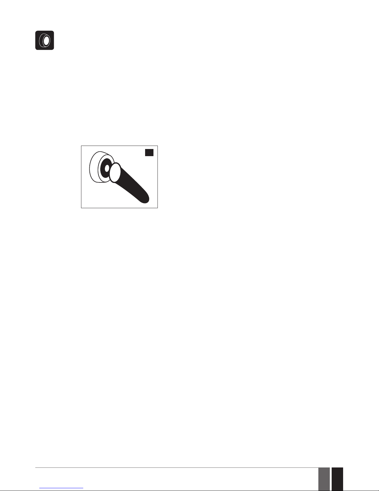
51
51
EN
ESIM384 Installation and Conguration Manual v1.1
12.6. iButton Key
To arm or disarm the system and turn OFF the alarm, touch the iButton key reader by any of 16 available iButton keys (see 11.
iBUTTON KEYS for iBut ton key management). When the iButton is touched to the iButton key reader for arming, the system
will proceed as follows:
Non-partitioned system:
• If ready (no violated zone/tamper), the system will initiate exit delay and arm.
• If unready, the system will not arm and provide a list of violated zones/tampers by SMS text message to user phone num-
ber. In such case the user must restore all violated zones and tampers before arming the system. Alternatively, the violated
zones can be bypassed (see 14.7. Bypassing and Activating Zones), disabled (see 14.9. Disabling and Enabling
Zones) or a Force attribute enabled (resulting in partial arm; see 14.6. Zone Attributes), while the tampers can be dis-
abled (see 16. TAMPERS).
Partitioned system:
• If all partitions are disarmed ready (no violated zone/tamper), the system will initiate exit delay and arm them.
• If one or more partitions are disarmed unready (violated zone/tamper is present), the system will arm the ready par tition
(-s) and skip the unready one (-s).
• If a combination of armed and disarmed ready partitions is present, the system will initiate exit delay, arm the disarmed
ready partitions and skip the armed ones.
35
When an iButton key is assigned to multiple partitions, the user will be able to arm/disarm the corresponding system partitions
by touching the iButton key to the reader. For example, if iButton 5 is assigned to Partition 1 and 4, the user will be able to arm/
disarm Partition 1 and 4 by touching iButton 5 to the reader. For more details on how to set iButton key partition, please refer
to 23.5. iButton Key Partition.
Page 52
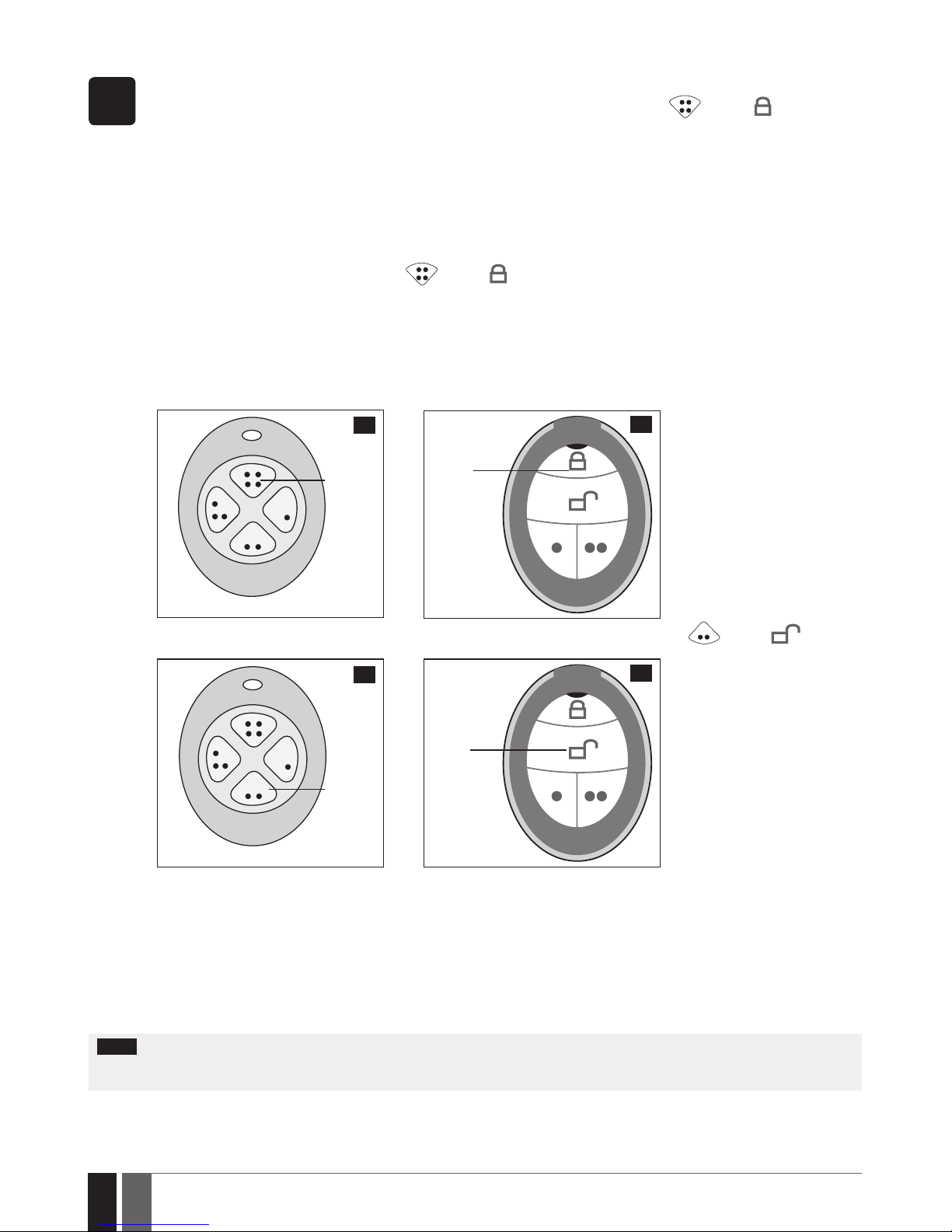
52
52
EN
ESIM384 Installation and Conguration Manual v1.1
12.7. EWK1/EWK2 Wireless Keyfob
EWK1/
EWK2
Non-partitioned system:
To arm the system, press 1 of 4 keyfob buttons set to arm the system (by default, EWK1 –
;EWK 2 - ). When EWK1/
EWK2 button is pressed for arming, the system will proceed as follows:
• If ready (no violated zone/tamper), the system will arm.
• If unready, the system will not arm. In such case the user must restore all violated zones and tampers before arming the
system. Alternatively, the violated zones can be bypassed (see 14.7. Bypassing and Activating Zones), disabled (see
14.9. Disabling and Enabling Zones) or a Force attribute enabled (resulting in partial arm; see 14.6. Zone Attributes),
while the tampers can be disabled (see 16. TAMPERS).
Partitioned system:
To arm the system, press 1 of 4 keyfob buttons with Partition Selection action assigned followed by a button with Arm the
System action assigned (by default, EWK1 –
;EWK 2 - ). When EWK1/EWK2 button is pressed for arming, the system
will proceed as follows:
• If all partitions are disarmed ready (no violated zone/tamper), the system will arm them.
• If one or more partitions are disarmed unready (violated zone/tamper is present), the system will arm the ready par tition
(-s) and skip the unready one (-s).
• If a combination of armed and disarmed ready partitions is present, the system will arm the disarmed ready partitions and
skip the armed ones.
Arm the
system
37
36
Arm the
system
To disarm the system, press 1 of 4 keyfob buttons set to disarm the system (by default, EWK1 -
; EWK2 - ).
Disarm
the
system
39
38
Disarm
the
system
To verify if the system has been successfully armed, do not release the Arm the System keyfob button and wait for the 3 short
keyfob buzzer’s beeps/indicator’s ashes indicating the successfully carried out command. The long beep/ash indicates the
unsuccessful command.
When a certain keyfob’s button is assigned to multiple partitions, the user will be able to arm/disarm the corresponding system
partition (-s) assigned to the button with Partition Selection action followed by a button with Arm the System/Disarm the
System action. For more details on how to set the keyfob partition, please refer to ELDES Conguration software‘s HELP section.
NOTE: Single EWK1/EWK2 keyfob button can be congured to carry out Partition Selection and Control Output/Output Toggle/Output Pulse
actions. In such case the PGM output control action will be executed with a 3-second delay once the button is pressed and in case it is not
followed within a 3-second period by a button with Arm the System or Disarm the System action assigned.
Page 53
53
53
EN
ESIM384 Installation and Conguration Manual v1.1
12.8. Arm-Disarm by Zone
ARM/
DISARM
ZONE
The Arm-Disarm by Zone feature allows to use a zone for arming and disarming the alarm system. The process is performed by
applying a low-level pulse for more than 3 seconds to the specied zone. It means that violating and restoring the zone leads to
system arming and by repeating this action the system becomes disarmed. The system will arm/disarm the partition (-s) that
the zone is assigned to. Up to 4 on-board zones can be set to arm/disarm up to 4 system partitions by this method.
Set zone for ArmDisarm by Zone
method
EKB2
Menu path:
OK → iiii → OK → ZONES → OK → ARM/DISARM BY ZONE → OK → ZONE 1... 4 → OK → nn
Value: iiii – 4-digit installer code; nn – on-board zone number, range – [01... 16].
EKB3/
EKB3W/
EWKB4
Enter parameter 34, on-board zone slot and zone number:
34 z nn #
Value: z – on-board zone slot for Arm-Disarm by Zone method; range - [1... 4]; nn – on-board
zone number, range – [01... 16].
Example: 34023#
ELDES
Conguration
software
This operation may be carried out from the PC using the ELDES Conguration software.
Disable Arm-Disarm by
Zone method
EKB2
Menu path:
OK → iiii → OK → ZONES → OK → ARM/DISARM BY ZONE → OK → ZONE 1... 4 → OK → 0
Value: iiii – 4-digit installer code.
EKB3/
EKB3W/
EWKB4
Enter parameter 34, on-board zone slot and parameter status value:
34 z 00 #
Value: z – on-board zone slot for Arm-Disarm by Zone method; range - [1... 4].
Example: 34200#
ELDES
Cong-
uration
software
This operation may be carried out from the PC using the ELDES Conguration software.
12.9. Automatic Arm/Disarm by Scheduler
The system comes equipped with an automatic arm/disarm feature that operates according to the specied weekday and time. This feature requires to set up the Start Time value of a certain scheduler and assign it to either Arm System or Disarm System action, which is
associated with a certain partition (all partitions).
Manage automatic
arm/disarm method
ELDES
Conguration
software
This operation may be carried out from the PC using the ELDES Conguration software.
For more details on the scheduler management, please refer to 18.6.2. Schedulers.
12.10. Disabling and Enabling Arm/Disarm Notications
By default, when the system is successfully armed or disarmed, it replies with conrmation by SMS text message to:
• user phone number, sharing the same partition as EKB2/EKB3/EKB3W/EWKB4 keypad and user/master code, iButton key, EWK1/
EWK2 wireless keyfob or zone, set up for Arm/Disarm by Zone method.
• user phone number that the system arming/disarming by free of charge phone call was initiated from.
• user phone number that the system arming/disarming by SMS text message was initiated from.
The conrmation SMS text message is sent to the user phone number regarding each partition separately and contains system status and
partition name as well as it may contain a user name assigned to user phone number, user/master code or iButton key. For more details on
names, please refer to 8.1. User Phone Number Names, 10.1. User/Master Code Names and 11.2. iButton Key Names.
To disable/enable this notication for individual user phone number, please refer to the following conguration methods.
Disable arm/disarm
notication
EKB2
Menu path:
System armed:
User phone number: OK → iiii → OK → SMS MESSAGES 1 → OK → SYS ARMED EVENT → OK →
GSM USER 1... 10 → OK → DISABLE → OK
SMS text message to all users simultaneously: ... → SYS ARMED EVENT → OK → SMS TO ALL
→ OK → DISABLE → OK
SMS delivery report: ... → SYS ARMED EVENT → OK → SMS REPORT → OK → DISABLE → OK
Page 54
54
54
EN
ESIM384 Installation and Conguration Manual v1.1
Disable arm/disarm
notication
EKB2
System disarmed:
User phone number: ... → SYS DISARMED EVENT → OK → GSM USER 1... 10 → OK → DISABLE
→ OK
SMS text message to all users simultaneously: ... → SYS DISARMED EVENT → OK → SMS TO
ALL → OK → DISABLE → OK
SMS delivery report: ... → SYS DISARMED EVENT → OK → SMS REPORT → OK → DISABLE→ OK
Value: iiii - 4-digit installer code.
EKB3/
EKB3W/
EWKB4
Enter parameter 25/21/55, event number, user phone number slot and parameter
status value:
System armed event
User phone number: 25 01 up 0 #
SMS text message to all users simultaneously: 21 01 0 #
SMS delivery report: 55 01 0 #
System disarmed event
User phone number: 25 02 up 0 #
SMS text message to all users simultaneously: 21 02 0 #
SMS delivery report: 55 02 0 #
Value: up - user phone number slot, range - [01... 10].
Example: 2502040#
ELDES
Conguration
software
This operation may be carried out from the PC using the ELDES Conguration software.
Enable arm/disarm
notication
EKB2
Menu path:
System armed:
User phone number: OK → iiii → OK → SMS MESSAGES 1 → OK → SYS ARMED EVENT → OK
→ GSM USER 1... 10 → OK → ENABLE → OK
SMS text message to all users simultaneously: ... → SYS ARMED EVENT → OK → SMS TO ALL
→ OK → ENABLE → OK
SMS delivery report: ... → SYS ARMED EVENT → OK → SMS REPORT → OK → ENABLE → OK
System disarmed:
User phone number: ... → SYS DISARMED EVENT → OK → GSM USER 1... 10 → OK → ENABLE
→ OK
SMS text message to all users simultaneously: ... → SYS DISARMED EVENT → OK → SMS TO
ALL → OK → ENBABLE → OK
SMS delivery report: ... → SYS DISARMED EVENT → OK → SMS REPORT → OK → ENABLE
→ OK
Value: iiii - 4-digit installer code.
EKB3/
EKB3W/
EWKB4
Enter parameter 25/21/55, event number, user phone number slot and parameter
status value:
System armed event
User phone number: 25 01 up 1 #
SMS text message to all users simultaneously: 21 01 1 #
SMS delivery report: 55 01 1 #
System disarmed event
User phone number: 25 02 up 1 #
SMS text message to all users simultaneously: 21 02 1 #
SMS delivery report: 55 02 1 #
Value: up - user phone number slot, range - [01... 10].
Example: 2502061#
ELDES
Conguration
software
This operation may be carried out from the PC using the ELDES Conguration software.
ATTENTION: The system will always deliver an SMS notication to the user after arming/disarming the system by SMS text message method
even if the arm/ disarm SMS notication is disabled.
For more details on how Send SMS text message to all users simultaneously and SMS delivery report parameters aect the SMS text message transmission, please refer to 27. SYSTEM NOTIFICATIONS.
Page 55
55
55
EN
ESIM384 Installation and Conguration Manual v1.1
13. EXIT AND ENTRY DELAY
When arming, the system initiates the exit delay countdown (by default – 15 seconds) intended for the user to leave the secured area. The
exit delay is indicated by short beeps emitted by EKB2/EKB3/EKB3W/EWKB4 keypad buzzer and buzzer, connected to the alarm system.
When arming:
• a non-partitioned system, a countdown timer will be displayed in the home screen view of EKB2 during exit delay.
• a partitioned system, EKB2 keypad will display ARMING part-name message on the screen for 2 seconds and switch to partition
selection menu during exit delay.
Exit delay is provided when arming the system by the following methods:
• EKB2/EKB3/EKB3W/EWKB4 keypad and user/master code.
• iButton key.
• Arm/Disarm by Zone.
To arm the system without exit delay, use one of the following system arming methods:
• Free of charge phone call.
• SMS text message.
• EWK1/EWK2/EWK2A wireless keyfob
• EGR100 middle-ware.
Set exit delay
SMS
SMS text message content:
ssss_EXITDELAY:p,ext or ssss_EXITDELAY:p,ext;p,ext;p,ext;p,ext
Value: ssss – 4-digit SMS password; p – partition number, range – [1... 4], ext – exit delay
duration, range – [0... 600] seconds.
Example: 1111_EXITDELAY:1,20;3,43
EKB2
Menu path:
OK → iiii → OK → PRIMARY SETTINGS → OK → EXIT DELAY → OK → PARTITION 1... 4 → OK →
ext → OK
Value: iiii – 4-digit installer code;, ext – exit delay duration, range – [0... 600] seconds.
EKB3/
EKB3W/
EWKB4
Enter parameter 72, partition number and exit delay duration:
72 pp ext #
Value: pp – partition number, range – [01... 04], ext – exit delay duration, range – [0... 600]
seconds.
Example: 7203259#
ELDES
Conguration
software
This operation may be carried out from the PC using the ELDES Conguration software.
NOTE: Alternatively, you can set exit delay value to “0” in order to arm the system without exit delay by any available method.
NOTE: EKB3/EKB3W/EWKB4 keypad buzzer will only beep if the keypad is operating in the partition where exit delay countdown is in
progress.
Page 56
56
56
EN
ESIM384 Installation and Conguration Manual v1.1
Once the exit delay has expired, the system initiates the entry delay countdown (by default – 15 seconds) if a Delay type zone is violated.
The countdown is indicated by short beeps emitted by keypad buzzer and by steady beep emitted by system’s buzzer. The indication is intended to advise the user that the system should be disarmed. Once the user presses/touches any key on the keypad during this delay, the
buzzer of the keypad will be silenced. If the system is disarmed before the entry delay expires, no alarm will be caused.
Set entry delay for
Delay zone
SMS
SMS text message content:
ssss_ENTRYDELAY:nn,eeeee or ssss_ENTRYDELAY:nn,eeeee;nn,eeeee;nn,eeeee;nn,eeeee
Value: ssss – 4-digit SMS password; nn – zone number, range – [1... 80], eeeee – entry delay
duration, range – [0... 9999] seconds.
Example: 1111_ENTRYDELAY:1,25;54,14;12,20
EKB2
Menu path:
On-board zone: OK → iiii → OK → ZONES → OK → ONBOARD ZONES → OK → ZONE 1... 16 → OK
→ ENTRY DELAY → OK → eeeee → OK
Wireless zone: OK → iiii → OK → WIRELESS ZONES → OK → WIRELESS ZONES 1... 4 → OK →
WIRELESS ZONE 13... 80 → OK → ENTRY DELAY → OK → eeeee → OK
Keypad zone: OK → iiii → OK → ZONES → OK → KEYPAD ZONES → OK → 1ST... 4TH KEYPAD
ZONE → OK → ENTRY DELAY → OK → eeeee → OK
EPGM1 zone: ... → EPGM1 ZONES 1-16... EPGM1 ZONES 17-32 → OK → EPGM1 ZONE 1... 32 →
OK → ENTRY DELAY → OK → eeeee → OK
Value: iiii – 4-digit installer code; eeeee – entry delay duration, range – [0... 9999] seconds.
EKB3/
EKB3W/
EWKB4
Enter parameter 54, partition number and entry delay duration:
54 nn eeeee #
Value: nn – zone number, range – [01... 80], eeeee – entry delay duration, range – [0... 9999]
seconds
Example: 5403259#
ELDES
Conguration
software
This operation may be carried out from the PC using the ELDES Conguration software.
NOTE: Due to battery power saving reasons, EKB3W/EWKB4 keypad buzzer will not sound during entry delay if the violated Delay type zone
is not of the associated EKB3W/EWKB4 keypad.
For more details on zone types, please refer to 14.5. Zone Type Denitions.
Page 57

57
57
EN
ESIM384 Installation and Conguration Manual v1.1
14. ZONES
Detection devices such as motion detectors and door contacts are connected to the alarm system’s zone terminals. Once connected, the
associated zone’s parameters must be congured.
ESIM384 comes equipped with 8 on-board zones allowing to connect up to 8 detection devices. For more details regarding zone expansion,
please refer to 14.2. Zone Expansion.
ESIM384 zones are classied by 5 categories:
Zone category Description
Max. number of
zones per device
Max. number of
zones in total
On-board zones Built-in wired zones of ESIM384 alarm system. 8/16* 8/16*
Keypad zones Hardwired zones of EKB2/EKB3/EKB3W/EWKB4 keypad. 1 4
EPGM1 zones Zones of EPGM1 - hardwired zone and PGM output expan-
sion module.
16 32
Wireless zones Non-physical zones automatically created by connected
wireless devices.
4** 64***
Virtual zones Non-physical zones intended for Panic button feature (alarm
activation upon pressing the button) on EWK1/EWK2 wireless keyfob. Virtual zones can be manually created using EL-
DES Conguration software.
64**** 64****
* - 8-Zone mode is enabled by default. ATZ mode doubles the on-board zone number and increases it to 16 in total.
** - Depends on the paired wireless device.
*** - Available only if no keypad zones, EPGM1 zones and virtual zones are present.
**** - Available only if no keypad zones, EPGM1 zones and wireless zones are present.
14.1. Zone Numbering
The zone numbers ranging from Z1 through Z16 are permanently reserved for on-board zones even when ATZ mode is disabled. The
Z17-Z80 zone numbers are automatically assigned in the chronological order to the created virtual zones and the devices connected to the
system: keypads, wireless devices, EPGM1 modules.
14.2. Zone Expansion
For additional detection device connection, the number of zones can be expanded by:
• enabling the ATZ (Advanced Technology zone) mode (see 14.4. ATZ (Advanced Technology Zone) Mode).
• connecting EPGM1 hardwired zone and PGM output expansion module.
• connecting keypads (see 32.1.1. EKB2 – LCD Keypad, 32.1.2. EKB3 – LED Keypad and 19.4. EKB3W/EWKB4 – Wireless LED
Keypad).
• pairing wireless devices (see 19. WIRELESS DEVICES).
• creating virtual zones (see ELDES Conguration software’s Help section).
The maximum supported number of zones is 80.
14.3. 8-Zone Mode
By default, ESIM384 alarm system runs in the 8-Zone mode under zone connection Type 1 allowing to connect up to 8 detection devices of
NO (normally-open) type to the on-board zone terminals as indicated in the wiring diagram of Type 1. Dierent zone connection types of
8-Zone mode can be individually assigned to each on-board zone.
The EPGM1 module supports “non ATZ” mode only, while the selected zone connection type applies to hardwired zones of EPGM1 module
altogether. By default, EPGM1 module runs under zone connection Type 1. However, a mixed combination of Type 1 and Type 2 zone connection types is supported simultaneously regardless of the type (Type 1 or Type 2) selected in the system’s conguration. Once Type 3 zone
connection type is selected, the detection device wiring on EPGM1 module zones must be done according to the wiring diagram of the
associated type.
The keypads support Type 1 and Type 2 wiring. A mixed combination of both zone connection types is supported by keypad zones.
Zone connection types featured by 8-Zone mode are following:
• Type 1 – Parallel wiring of NO (normally-open) detection device with 5,6k EOL (end-of-line) resistor.
• Type 2 – Consecutive wiring of NC (normally-closed) detection device with 5,6k EOL resistor.
• Type 3 – Combination of serial and parallel wiring of tamper with 5,6k EOL resistor and NC detection device with 3,3k EOL resistor.
For zone wiring diagrams of the “non ATZ” mode, please refer to 2.3.2. Zone Connection Types.
Page 58
58
58
EN
ESIM384 Installation and Conguration Manual v1.1
Set zone connection
type of “non ATZ”
mode for on-board and
EPGM1 zones
ELDES
Cong-
uration
soft-
ware
This operation may be carried out from the PC using the ELDES Conguration software.
NOTE: Type 3 is NOT supported by keypad zones.
14.4. ATZ (Advanced Technology Zone) Mode
The ATZ mode is a software-based feature that doubles the number of on-board zones and enables two detection devices to be installed
per 1 zone terminal. Once this mode is enabled, the zone connection Type 4 is set automatically. The detection devices must be wired to the
on-board zone terminals as indicated in the wiring diagram of the associated zone connection type. Dierent zone connection types of ATZ
mode can be individually assigned to each on-board zone pair i.e. Z1 - Z9, Z2 - Z10 etc. .
Once enabled, the ATZ mode DOES NOT aect EPGM1 zones, nor keypad zones and applies to on-board zones only. The ATZ mode is NOT supported by EPGM1 and keypad zones.
Zone connection types featured by ATZ mode are the following:
• Type 4 – Parallel wiring of 2 NC (normally-closed) detection devices with 5,6k and 3,3k EOL (end-of-line) resistors respectively.
5,6k EOL resistor corresponds to zones ranging from Z1 through Z8, while 3,3k EOL resistor corresponds to zones ranging from Z9
through Z16.
• Type 5 – Combination of consecutive and parallel wiring of tamper with 5,6k EOL resistor and 2 NC (normally-closed) detection devic-
es with 5,6k and 3,3k EOL resistors respectively. 5,6k EOL resistor corresponds to zones ranging from Z1 through Z8, while 3,3k
EOL resistor corresponds to zones ranging from Z9 through Z16.
For zone wiring diagrams of the ATZ mode, please refer to 2.3.2. Zone Connection Types.
Enable ATZ mode
EKB2
Menu path:
OK → iiii → OK → ZONES → OK → ATZ MODE → OK → ENABLE → OK
Value: iiii – 4-digit installer code.
EKB3/
EKB3W/
EWKB4
Enter parameter 28 and parameter status value:
28 1 #
Example: 281#
ELDES
Conguration
software
This operation may be carried out from the PC using the ELDES Conguration software.
Disable ATZ mode
EKB2
Menu path:
OK → iiii → OK → ZONES → OK → ATZ MODE → OK → DISABLE → OK
Value: iiii – 4-digit installer code.
EKB3/
EKB3W/
EWKB4
Enter parameter 28 and parameter status value:
28 0 #
Example: 280#
ELDES
Conguration
soft-
ware
This operation may be carried out from the PC using the ELDES Conguration software.
Set zone connection
type of ATZ mode for
on-board zones
ELDES
Conguration
soft-
ware
This operation may be carried out from the PC using the ELDES Conguration software.
14.5. Zone Type Denitions
Page 59
59
59
EN
ESIM384 Installation and Conguration Manual v1.1
• Interior Follower – The zone can be violated during exit and entry delay without causing an alarm. If the zone is violated before the
entry delay has begun, it will cause an instant alarm followed by single notication delivery even if the zone has been violated multiple
times while alarm period (by default - 1 minute) is in progress. If another Interior Follower-type zone has been violated it should act in
the same way - cause an instant alarm followed by single notication delivery even if the zone has been violated multiple times while
alarm period (by default - 1 minute) is in progress.
• Instant – The alarm is instantly caused if this zone is violated when the system is armed or during entry delay. This zone type is usually
used for doors, windows, shock sensors or other zones.
• 24-Hour – When the system is either armed or disarmed, the zone will cause instant alarm if violated. Normally, this type of zone is
used for securing the areas that require constant supervisory.
• Delay – This zone type can be violated during exit and entry delay without causing an alarm. If the zone is violated when the system
is armed, it will initiate entry delay countdown intended for the user to disarm the system. If the zone remains violated after the exit
delay expires, it will cause an instant alarm. Typically, this zone type is used for door contacts installed at designated exit/entry doors.
• Fire – If this zone type is violated when the system is either armed or disarmed, the alarm will be instantly caused and the siren/bell
will emit pulsating sound. Once the alarm is caused by violating a Fire-type zone followed by turning OFF the alarm using any available
disarm method, the system will ignore the violations of any Fire-type zone (including the repeated violations of the said zone) caused
within a 1-minute time frame. Typically, this zone type is used for ame and smoke detectors.
• Panic/Silent – This zone operates the same as 24-Hour zone type, but the system will not activate the siren/bell and keypad buzzer if
violated. Normally, this zone type used for panic alarm buttons.
• CO Sensor – This zone type operates identically to Fire zone type and it is used for CO (carbon monoxide) detector.
• Report/Control – This zone operates the same as Panic/Silent zone type, but unique event data message will be transmitted to the
monitoring station if violated. However, no alarm will be caused - the system will NOT dial the listed user phone number regardless of
the status of Call in Case of Alarm feature (enabled or disabled), nor the siren will sound. Typically, this zone type is used to report a
certain non-alarm event, such as heating activation or fault.
• Instant Silent – This zone operates in the same way as Panic/Silent, but only when the system is armed.
Set zone type for
individual zone
EKB2
Menu path:
On-board zone: OK → iiii → OK → ZONES → OK → ONBOARD ZONES → OK → ZONE 1... 16 → OK
→ TYPE → OK → INTERIOR FOLLOWER | INSTANT | 24- HOUR | DELAY | FIRE | PANIC/SILENT |
CO SENSOR | REPORT/CTRL | INSTANT SILENT → OK
Wireless zone: OK → iiii → OK → WIRELESS ZONES → OK → WIRELESS ZONES 1... 4 → OK →
WIRELESS ZONE 13... 80 → OK → TYPE → OK → INTERIOR FOLLOWER | INSTANT | 24-HOUR |
DELAY | FIRE | PANIC/SILENT | CO SENSOR | REPORT/CTRL | INSTANT SILENT → OK
Keypad zone: OK → iiii → OK → ZONES → OK → KEYPAD ZONES → OK → 1ST... 4TH KEYPAD
ZONE → OK → TYPE → OK → INTERIOR FOLLOWER | INSTANT | 24-HOUR | DELAY | FIRE |
PANIC/SILENT | CO SENSOR | REPORT/CTRL | INSTANT SILENT → OK
EPGM1 zone: ... → 1...8. EPGM1 ZONES 1-16... EPGM1 ZONES 17-32 → OK → EPGM1 ZONE 1...
32 → OK → INTERIOR FOLLOWER | INSTANT | 24-HOUR | DELAY | FIRE | PANIC/SILENT | CO
SENSOR | REPORT/CTRL | INSTANT SILENT→ OK
Value: iiii – 4-digit installer code.
EKB3/
EKB3W/
EWKB4
Enter parameter 53, zone number and zone type number:
53 nn 1 # – Interior Follower
53 nn 2 # – Instant
53 nn 3 # – 24-Hour
53 nn 4 # – Delay
53 nn 5 # – Fire
53 nn 6 # – Panic/Silent
53 nn 7 # – CO Sensor
53 nn 8 # – Report/Control
53 nn 9 # – Instant Silent
Value: nn – zone number, range – [01... 80]
Example: 53125#
ELDES
Cong-
uration
software
This operation may be carried out from the PC using the ELDES Conguration software.
NOTE: The system will NOT activate siren and keypad buzzer only when Panic/Silent, Report/Control or Instant Silent zone type is violated.
14.6. Zone Attributes
• Stay – If this attribute is enabled, the zone, regardless of its type, will not cause an alarm if violated when the system is STAY-armed.
By enabling this attribute, Alarm Count to Bypass feature will not operate with the same zone. For more details on arming the system
in the Stay mode, please refer to 15. STAY MODE.
• Force – This attribute determines whether the system can be armed or not while a zone is violated resulting in partial arm event. If a
Page 60
60
60
EN
ESIM384 Installation and Conguration Manual v1.1
zone with the Force attribute enabled remains violated until the exit delay expires, it will be ignored. Once the system is partially armed
followed by zone restore, the violation of this zone will no longer be ignored and the zone will operate according to the determined
type. For more details on zone types, please refer to 14.5. Zone Type Denitions.
• Shared – This attribute determines whether a zone, assigned to multiple partitions, will cause an alarm or not in the associated armed
partition if violated. If a zone with the Shared attribute enabled is violated when at least one of the associated partitions is disarmed,
the alarm will not be caused. Once the system is armed in all of the associated partitions, the zone with Shared attribute enabled will
operate according to the determined type. Typically, this attribute is used for shared areas, such as corridors.
• Delay, s – This attribute determines the zone sensitivity level by delay time (by default – 15 seconds). If the zone remains triggered until the
delay time expires, the zone is considered violated. This attribute does not apply to wireless zones, keypad zones and virtual zones.
• Cross-Zone/Intelli-Zone is a method used to prevent false alarms. The system will not cause an alarm unless two associated zones
are violated within a specied time period, known as Alarm Conrmation Timeout. By associating a certain zone to itself, the system
would cause an alarm only if the zone has been violated repeatedly within the Alarm Conrmation Timeout. This feature operates with
all zone categories including virtual zones.
• Delay becomes Instant in Stay mode – This attribute determines whether or not any Delay type zone will operate as Instant type
zone when the system is armed in the Stay mode. When the system is fully armed, the Delay type zone will operate normally. For more
details on Delay and Instant zone types, please refer to 14.5. Zone Type Denitions.
• Chime – This feature is used to emit 3 short beeps from the keypad buzzer whenever any Delay type zone is violated while the system
is disarmed. Typically, the feature is used for designated exit/entry doors to indicate the opening of the doors.
• Bell - This attribute operates identically as Chime and applies to EKB3W/EWKB4 keypad only.
• Alarm Count to Bypass – This attribute determines a number of times the zone can be violated until it is automatically bypassed. It
can be assigned to Interior Follower, Instant, Delay and Instant Silent zone types only. Alarm Count to Bypass becomes inactive once
the Stay attribute is enabled on the same zone. For more details on zone bypassing and how to activate a bypassed zone, please refer
to 14.7. Bypassing and Activating Zones.
NOTE: Due to battery power saving reasons, EKB3W/EWKB4 wireless keypad buzzer will not sound if the Bell attribute is not enabled and the
violated Delay type zone is not of the associated EKB3W/EWKB4 wireless keypad. For more details on EKB3W/EWKB4 wireless keypad, please
refer to 19.5. EKB3W/EWKB4 – Wireless LED Keypad.
Enable Stay attribute
for individual zone
EKB2
Menu path:
On-board zone: OK → iiii → OK → ZONES → OK → ONBOARD ZONES → OK → ZONE 1... 16 → OK
→ STAY → OK → ENABLE → OK
Wireless zone :OK → iiii → OK → WIRELESS ZONES → OK → WIRELESS ZONES 1... 4 → OK →
WIRELESS ZONE 13... 80 → OK → STAY → OK → ENABLE → OK
Keypad zone: OK → iiii → OK → ZONES → OK → KEYPAD ZONES → OK → 1ST... 4TH KEPAD
ZONE → OK → STAY → OK → ENABLE → OK
EPGM1 zone: ... → EPGM1 ZONES 1-16... EPGM1 ZONES 17-32 → OK → 1...8. EPGM1 ZONE 1...
32 → OK → STAY → OK → ENABLE → OK
Value: iiii – 4-digit installer code.
EKB3/
EKB3W/
EWKB4
Enter parameter 56, zone number and parameter status value:
56 nn 1 #
Value: nn – zone number, range – [01... 80].
Example: 56041#
ELDES
Conguration
software
This operation may be carried out from the PC using the ELDES Conguration software.
Disable Stay attribute
for individual zone
EKB2
Menu path:
On-board zone: OK → iiii → OK → ZONES → OK → ONBOARD ZONES → OK → ZONE 1... 16 →
OK → STAY → OK → DISABLE → OK
Wireless zone: OK → iiii → OK → WIRELESS ZONES → OK → WIRELESS ZONES 1... 4 → OK →
WIRELESS ZONE 13... 80 → OK → STAY → OK → DISABLE → OK
Keypad zone: OK → iiii → OK → ZONES → OK → KEYPAD ZONES → OK → 1ST... 4TH KEYPAD
ZONE → OK → STAY → OK → DISABLE → OK
EPGM1 zone: ... → EPGM1 ZONES 1-16... EPGM1 ZONES 17-32 → OK → 1...8. EPGM1 ZONE 1...
32 → OK → STAY → OK → DISABLE → OK
Value: iiii – 4-digit installer code.
EKB3/
EKB3W/
EWKB4
Enter parameter 56, zone number and parameter status value:
56 nn 0 #
Value: nn – zone number, range – [01... 80].
Example: 56190#
Page 61
61
61
EN
ESIM384 Installation and Conguration Manual v1.1
ELDES
Conguration
software
This operation may be carried out from the PC using the ELDES Conguration software.
Enable Force attribute
for individual zone
EKB2
Menu path:
On-board zone: OK → iiii → OK → ZONES → OK → ONBOARD ZONES → OK → ZONE 1... 16 → OK
→ FORCE → OK → ENABLE → OK
Wireless zone: OK → iiii → OK → WIRELESS ZONES → OK → WIRELESS ZONES 1... 4 → OK →
WIRELESS ZONE 13... 80 → OK → FORCE → OK → ENABLE → OK
Keypad zone: OK → iiii → OK → ZONES → OK → KEYPAD ZONES → OK → 1ST... 4TH KEYPAD
ZONE → OK → FORCE → OK → ENABLE → OK
EPGM1 zone: ... → EPGM1 ZONES 1-16... EPGM1 ZONES 17-32 → OK → 1... 8. EPGM1 ZONE 1...
32 → OK → FORCE → OK → ENABLE → OK
Value: iiii – 4-digit installer code.
EKB3/
EKB3W/
EWKB4
Enter parameter 82, zone number and parameter status value:
82 nn 1 #
Value: nn – zone number, range – [01... 80].
Example: 82061#
ELDES
Conguration
software
This operation may be carried out from the PC using the ELDES Conguration software.
Disable Force
attribute for
individual zone
EKB2
Menu path:
On-board zone: OK → iiii → OK → ZONES → OK → ONBOARD ZONES → OK → ZONE 1... 16 → OK
→ FORCE → OK → DISABLE → OK
Wireless zone: OK → iiii → OK → WIRELESS ZONES → OK → WIRELESS ZONES 1... 4 → OK →
WIRELESS ZONE 13... 80 → OK → FORCE → OK → DISABLE → OK
Keypad zone: OK → iiii → OK → ZONES → OK → KEYPAD ZONES → OK → 1ST... 4TH KEYPAD
ZONE → OK → FORCE → OK → DISABLE → OK
EPGM1 zone: ... → EPGM1 ZONES 1-16... EPGM1 ZONES 17-32 → OK → 1...8. EPGM1 ZONE 1...
32 → OK → FORCE → OK → DISABLE → OK
Value: iiii – 4-digit installer code.
EKB3/
EKB3W/
EWKB4
Enter parameter 82, zone number and parameter status value:
82 nn 0 #
Value: nn – zone number, range – [01... 80].
Example: 82110#
ELDES
Conguration
software
This operation may be carried out from the PC using the ELDES Conguration software.
Enable/disable
Shared attribute for
individual zone
ELDES
Conguration
software
This operation may be carried out from the PC using the ELDES Conguration software.
Set Delay,s attribute
ELDES
Conguration
software
This operation may be carried out from the PC using the ELDES Conguration software.
Enable/disable Delay
becomes Instant in
Stay mode attribute
ELDES
Conguration
software
This operation may be carried out from the PC using the ELDES Conguration software.
Page 62
62
62
EN
ESIM384 Installation and Conguration Manual v1.1
Disable Chime
attribute
EKB2
Menu path:
OK →iiii → OK → ZONES → OK → CHIME → OK → DISABLE → OK
Value: iiii – 4-digit installer code.
EKB3/
EKB3W/
EWKB4
Enter parameter 32 and parameter status value:
32 0 #
Example: 320#
ELDES
Cong-
uration
software
This operation may be carried out from the PC using the ELDES Conguration software.
Enable Chime attribute
EKB2
Menu path:
OK →iiii → OK → ZONES → OK → CHIME → OK → ENABLE → OK
Value: iiii – 4-digit installer code.
EKB3/
EKB3W/
EWKB4
Enter parameter 32 and parameter status value:
32 1 #
Example: 321#
ELDES
Cong-
uration
software
This operation may be carried out from the PC using the ELDES Conguration software.
By default, Cross-Zone/Intelli-Zone is not set. To associate two zones and/or set the Alarm Conrmation Timeout, please refer to the following conguration method.
Associate a zone for
Cross-Zone/Intelli-Zone
attribute
ELDES
Conguration
soft-
ware
This operation may be carried out from the PC using the ELDES Conguration software.
Set Alarm
Conrmation Timeout
ELDES
Conguration
soft-
ware
This operation may be carried out from the PC using the ELDES Conguration software.
Set Alarm Count to
Bypass attribute for
individual zone
ELDES
Conguration
soft-
ware
This operation may be carried out from the PC using the ELDES Conguration software.
ATTENTION: Cross-Zone/Intelli-Zone feature is NOT recommended in case it is necessary to bypass the associated zone, otherwise the zone
that requires alarm conrmation will never cause an alarm when violated.
Page 63
63
63
EN
ESIM384 Installation and Conguration Manual v1.1
14.7. Bypassing and Activating Zones
NOTE for EKB3/EKB3W/EWKB4: The Conguration mode must remain deactivated before bypassing a violated zone or activating a by-
passed zone.
Zone bypassing allows the user to deactivate a violated zone and arm the system without restoring the zone. If a bypassed zone is violated
or restored during exit/entry delay, or when then system is armed, it will be ignored. When a zone is bypassed, EKB3/EKB3W/EWKB4 keypad indicator
will light ON and EKB2 keypad will display icon in the home screen view.
Bypass individual
violated zone
EKB2
Menu path:
OK → uumm → OK → BYPASS → OK → BYPASS LIST 1... 9 → OK → Z1-zone-name... Z80-zone-
name → OK → BYPASS → OK
Value: uumm – 4-digit user/master code; zone-name – up to 24 characters zone name.
EKB3/
EKB3W/
EWKB4
Press the key, enter zone number and user/master code:
nn uumm #
Value: nn – zone number, range – [01... 80]; uumm – 4-digit user/master code.
Example:
091111#
Bypass all violated
zones
EKB2
Menu path:
OK → uumm → OK →BYPASS → OK → BYP VIOLATED ZONES → OK
Value: uumm – 4-digit user/master code.
The zone will remain bypassed until the system is disarmed. Once the system is disarmed, the corresponding zone state will be indicated
on the keypads (see 32.1.1. EKB2 – LCD Keypad, 32.1.2. EKB3 – LED Keypad and 19.5. EKB3W/EWKB4 – Wireless LED Keypad )
and Info SMS text message (see 26. SYSTEM INFORMATION. INFO SMS). Alternatively, the user can activate the bypassed zone by the
following conguration methods.
Activate bypassed
zone
EKB2
Menu path:
OK → uumm → OK → BYPASS → OK → BYPASS LIST 1... 9 → OK → Z1-zone-name... Z80-zone-
name → OK → UNBYPASS → OK
Value: uumm – 4-digit user/master code; zone-name – up to 24 characters zone name.
EKB3/
EKB3W/
EWKB4
Press the key, enter zone number and user/master code:
nn uumm #
Value: nn – zone number, range – [01... 80]; uumm – 4-digit user/master code.
Example:
251111#
NOTE: Zones can only be bypassed and activated when the system is not armed.
14.8. Zone Names
Each zone has a name that can be customized by the user. Typically, the name species a device type connected to a determined zone
terminal, for Example: Kitchen doors opened. The zone names are used in SMS text messages that are sent to the user during alarm, the
By default, the zone names are: Z1 – Zone1, Z2 – Zone2, Z3 – Zone3, Z4 – Zone4 etc.
Set zone name
SMS
SMS text message content:
ssss_Znn:zone-name
Value: ssss – 4-digit SMS password; nn – zone number, range – [1... 80]; zone-name – up to
24 characters zone name.
Example: 1111_Z3:Door sensor triggered
ELDES
Conguration
software
This operation may be carried out from the PC using the ELDES Conguration software.
Page 64
64
64
EN
ESIM384 Installation and Conguration Manual v1.1
View zone names
SMS
SMS text message content:
ssss_STATUS
Value: ssss – 4-digit SMS password.
Example: 1111_STATUS
EKB2
Menu path:
On-board zone: OK → iiii → OK → ZONES → OK → ONBOARD ZONES → OK → ZONE 1... 16 →
OK → NAME
Wireless zone: OK → iiii → OK → WIRELESS ZONES → OK → WIRELESS ZONES 1... 4 → OK →
WIRELESS ZONE 13... 80 → OK → NAME
Keypad zone: OK → iiii → OK → ZONES → OK → KEYPAD ZONES → OK → 1ST... 4TH KEYPAD
ZONE → OK → NAME
EPGM1 zone: ... → EPGM1 ZONES 1-16... EPGM1 ZONES 17-32 → OK → 1... 8. EPGM1 ZONE 1...
32 → OK → NAME
Value: iiii – 4-digit installer code.
ELDES
Conguration
software
This operation may be carried out from the PC using the ELDES Conguration software.
ATTENTION: Colon, semi-colon characters, parameter names and/or values, such as PSW, STATUS, ON, OFF etc. are NOT allowed in zone
names
NOTE: Multiple zone names can be set by a single SMS text message, Example: 1111_Z1:Kitchen doors opened;Z3:Movement in base-
ment;Z4:Bedroom window opened
14.9. Disabling and Enabling Zones
By default, all zones, except keypad and virtual zones, are enabled. To permanently disable/enable an individual zone, please refer to the
following conguration methods.
Disable zone
SMS
SMS text message content:
ssss_Znn:OFF
Value: ssss – 4-digit SMS password; nn – zone number, range – [1... 80].
Example: 1111_Z13:OFF
EKB2
Menu path:
On-board zone: OK → iiii → OK → ZONES → OK → ONBOARD ZONES → OK → ZONE 1... 16 →
OK → STATUS → OK → DISABLE → OK
Wireless zone: OK → iiii → OK → WIRELESS ZONES → OK → WIRELESS ZONES 1... 4 → OK →
WIRELESS ZONE 13... 80 → OK → STATUS → OK → DISABLE → OK
Keypad zone: OK → iiii → OK → ZONES → OK → KEYPAD ZONES → OK → 1ST... 4TH KEYPAD
ZONE → OK → STATUS → DISABLE → OK
EPGM1 zone: ... → EPGM1 ZONES 1-16... EPGM1 ZONES 17-32 → OK → 1... 8. EPGM1 ZONE 1...
32 → OK → STATUS → DISABLE → OK
Value: iiii – 4-digit installer code.
EKB3/
EKB3W/
EWKB4
Enter parameter 52, zone number and parameter status value:
52 nn 0 #
Value: nn – zone number, range – [01... 80].
Example: 52360#
ELDES
Conguration
software
This operation may be carried out from the PC using the ELDES Conguration software.
Enable zone
SMS
SMS text message content:
ssss_Znn:ON
Value: ssss – 4-digit SMS password; nn – zone number, range – [1... 80].
Example: 1111_Z6:ON
Page 65
65
65
EN
ESIM384 Installation and Conguration Manual v1.1
EKB2
Menu path:
On-board zone: OK → iiii → OK → ZONES → OK → ONBOARD ZONES → OK → ZONE 1... 16 → OK
→ STATUS → OK → ENABLE → OK
Wireless zone: OK → iiii → OK → WIRELESS ZONES → OK → WIRELESS ZONES 1... 4 → OK →
WIRELESS ZONE 13... 80 → OK → STATUS → OK → ENABLE → OK
Keypad zone: OK → iiii → OK → ZONES → OK → KEYPAD ZONES → OK → 1ST... 4TH KEYPAD
ZONE → OK → STATUS → ENABLE → OK
EPGM1 zone: ... → EPGM1 ZONES 1-16... EPGM1 ZONES 17-32 → OK → 1... 8. EPGM1 ZONE 1...
32 → OK → STATUS → ENABLE → OK
Value: iiii – 4-digit installer code.
EKB3/
EKB3W/
EWKB4
Enter parameter 52, zone number and parameter status value:
52 nn 1 #
Value: nn – zone number, range – [01... 80].
Example: 52151#
ELDES
Cong-
uration
software
This operation may be carried out from the PC using the ELDES Conguration software.
14.10. Viewing Zone State
The zone state (violated/restored) is indicated in real-time by all available conguration methods. However, the most convenient way to
view the zone state is using the graphical interface of ELDES Conguration software as follows:
• Red-zoneisviolated.
• Green-zoneisrestored.
• Grey-zoneisdisabled.
To view the zone state, please refer to the following conguration methods.
View zone state
SMS
SMS text message content:
ssss_INFO
Value: ssss – 4-digit SMS password.
Example: 1111_INFO
EKB2
Menu path:
OK → uumm → OK → VIOLATED ZONES → OK → ZONE 1... 80
Value: uumm – 4-digit user/master code.
EKB3/
EKB3W/
EWKB4
Please, refer to illuminated zone indicators ranging from 1 through 12 on the keypad. The
ashing indicator
represents violated high-numbered zones (Z13-Z80). For more details
on violated high-numbered zone indication, please refer to 29. INDICATION OF SYS TEM
FAULTS.
Page 66
66
66
EN
ESIM384 Installation and Conguration Manual v1.1
15. STAY MODE
Stay mode allows the user to arm and disarm the alarm system without leaving the secured area. If the zones with Stay attribute enabled
are violated when the system is STAY-armed, no alarm will be caused. Typically, this feature is used when arming the system at home before
going to bed.
The system can be STAY-armed under the following conditions:
• If a Delay-type zone is NOT violated during exit delay and a zone (-s) with Stay attribute enabled exists, the system will arm in Stay
mode. When arming the system in Stay mode under this condition, one of the available arming methods must be used that provide exit
delay. For more details on these methods, please refer to 13. EXIT AND ENTRY DELAY.
• The system will instantly arm in Stay mode when using one of the following methods.
Arm the system in
Stay mode
EKB2
Menu path:
Non-partitioned system: P2 → uumm → OK
Partitioned system: P2 → uumm → OK → [p] part-name → OK
Value: uumm – 4-digit user/master code; p – partition number, range – [1... 4]; part-name – up
to 15 characters partition name.
EKB3/
EKB3W/
EWKB4
Press the key and enter user/master:
uumm
Value: uumm – 4-digit user/master code.
Example:
1111
EWK1/
EWK2
This operation may be carried out from the wireless keyfob if pre-assigned using the PC running ELDES Conguration software.
When one or more system partitions are successfully armed in Stay mode, EKB2 keypad will display
icon in the home screen view.
NOTE for EKB3/EKB3W/EWKB4: The Conguration mode must be deactivated, when Stay-arming the system.
NOTE: The system can be armed in Stay mode, only if there is at least one zone with Stay attribute enabled.
NOTE: Stay mode is not supported by virtual zones.
NOTE: The system can also be instantly STAY-armed using ELDES Cloud Services.
For more details on how to enable Stay attribute for zone, please refer to 14.6. Zone Attributes.
Page 67
67
67
EN
ESIM384 Installation and Conguration Manual v1.1
16. TAMPERS
The tamper circuit is a single closed loop such that a break in the loop at any point will cause a tamper alarm regardless of the system
status – armed or disarmed. During the tamper alarm, the system will activate the siren/bell and the keypad buzzer and send the SMS text
message to the listed user phone number. The system will cause tamper alarm under the following conditions:
• If the enclosure of a detection device, siren/bell, metal cabinet or keypad is opened, the physical tamper switch will be triggered. By
default, indicated as Tamper x in the SMS text message (x = tamper number). User is able to change tamper’s name if he preers to
(see 16.1. Tamper names). Alternatively, the tamper switch can be connected to a zone resulting in zone alarm when tampered (see
15. ZONES).
• If the wireless signal is lost due to low signal level or low battery power on a certain wireless device (see 19.3. Wireless Signal Status
Monitoring).
By default, all tampers and tamper alarm notication by SMS text message is enabled. To disable/enable a certain tamper and/or tamper
alarm notication, please refer to the following conguration methods:
Disable/enable
tamper
ELDES
Conguration
software
This operation may be carried out from the PC using the ELDES Conguration software.
View violated tampers
SMS
The system will automatically send an SMS text message, containing a violated tamper
name, to user phone number.
EKB2
EKB2 Menu path:
OK → uumm → OK → VIOLATED TAMPERS → OK → TAMPER 1... 80
Value: uumm – 4-digit user/master code.
EKB3/
EKB3W/
EWKB4
The illuminated indicator represents system fault presence including violated tam per.
For more details on violated tamper indication, please refer to 29. INDICATION OF SYS TEM
FAULTS.
Disable tamper alarm
notication
EKB2
Menu path:
User phone number: OK → iiii → OK → SMS MESSAGES 1 → OK → TAMPER ALARM → OK →
GSM USER 1... 10 → OK → DISABLE → OK
SMS text message to all users simultaneously: ... → TAMPER ALARM → OK → SMS TO ALL →
OK → DISABLE → OK
SMS delivery report: ... → TAMPER ALARM → OK → SMS REPORT → OK → DISABLE → OK
Value: iiii – 4-digit installer code.
EKB3/
EKB3W/
EWKB4
Enter parameter 25/21/55, event number, user phone number slot and parameter
status value:
User phone number: 25 13 up 0 #
SMS text message to all users simultaneously: 21 13 0 #
SMS delivery report: 55 13 0 #
Value: up - user phone number slot, range - [01... 10].
Example: 2513030#
ELDES
Cong-
uration
software
This operation may be carried out from the PC using the ELDES Conguration software.
Enable tamper alarm
notication
EKB2
Menu path:
User phone number: OK → iiii → OK → SMS MESSAGES 1 → OK → TAMPER ALARM → OK →
GSM USER 1... 10 → OK → ENABLE → OK
SMS text message to all users simultaneously: ... → TAMPER ALARM → OK → SMS TO ALL →
OK → ENABLE → OK
SMS delivery report: ... → TAMPER ALARM → OK → SMS REPORT → OK → ENABLE → OK
Value: iiii – 4-digit installer code.
Page 68
68
68
EN
ESIM384 Installation and Conguration Manual v1.1
EKB3/
EKB3W/
EWKB4
Enter parameter 25/21/55, event number, user phone number slot and parameter
status value:
User phone number: 25 13 up 1 #
SMS text message to all users simultaneously: 21 13 1 #
SMS delivery report: 55 13 1 #
Value: up - user phone number slot, range - [01... 10].
Example: 2513041#
ELDES
Cong-
uration
soft-
ware
This operation may be carried out from the PC using the ELDES Conguration software.
For more details on how to view violated tamper, please refer to 17. ALARM INDICATIONS AND NOTIFICATIONS FOR USER.
ATTENTION: Once a certain tamper is disabled, the system will NOT deliver any text message regarding the physical tamper violation nor
wireless signal loss or restore.
ATTENTION: The system will NOT deliver any text message regarding wireless signal loss or restore while the physical tamper violation is
in progress.
ATTENTION: The system will NOT cause any tamper alarm regarding the physical tamper violation nor wireless signal loss if the associated
zone is disabled (excepting EWKB 4 on board zone).
16.1. Tamper Names
Each tamper has a name that can be customized by the user. The tamper names are used in SMS text messages that are sent to the user
during the tamper alarm. By default, the tamper names are: Tamper 1, Tamper 2, Tamper 3, Tamper 4 etc. To set a dierent tamper name,
please refer to the following conguration methods.
Manage tamper name
ELDES
Cong-
uration
software
This operation may be carried out from the PC using the ELDES Conguration software.
Page 69

69
69
EN
ESIM384 Installation and Conguration Manual v1.1
17. ALARM INDICATIONS AND NOTIFICATIONS FOR USER
When a zone, depending on zone type (see 14.5. Zone Type Denitions), or tamper is violated, the system will cause an alarm. By de-
fault, the alarm duration is 1 minute (see 20. SIREN/BELL regarding the alarm duration). During the alarm, the system will follow this
pattern:
1. The system activates the siren/bell and the keypad buzzer.
a) The siren/bell will emit pulsating sound if the violated zone is of Fire type, otherwise the sound will be steady.
b) The keypad buzzer will emit short beeps.
c) EKB2 keypad will display
icon next to the alarmed partition in the home screen view followed by icon indicating the presence of
the alarm events in the alarm log (see 28. EVENT AND ALARM LOG). In case a Fire-type zone is violated in any system partition,
icon will appear in the home screen view.
d) EKB3 keypad operating in 4-partition mode will ash the [1]... [4] key corresponding to the alarmed partition number.
e) If one or more zones are violated, EKB3/EKB3W/EWKB4 will light ON the corresponding violated zone indicator (-s) ranging from 1
through 12. Indicator
will ash if one or more high-numbered zones are violated. If one or tampers are violated, indicator will
light ON. For more details on viewing violated high-numbered zone and tamper numbers by EKB3/EKB3W/EWKB4 keypad, please
refer to 29. INDICATION OF SYSTEM FAULTS.
2. The system attempts to send an SMS text message, containing the violated zone/tamper name (see 14.8. Zone Names and 16.1. Tam-
per Names on how to set a zone and tamper name respectively), to the rst listed user phone number, sharing the same partition as the
violated zone/tamper. The system will send SMS text messages regarding each violated zone/tamper separately.
a) If the SMS cascade option is enabled and the user phone number is unavailable,then the system will attempt to send the SMS text
message to the next listed user phone number, assigned to the same partition as the previous one. The user phone number may be
unavailable due to the following reasons:
• mobile phone was switched o.
• was out of GSM signal coverage.
b) The system will continue sending the SMS text message to the next listed user phone numbers in the priority order until one is availa-
ble. The system sends the SMS text message only once and will not return to the rst user phone number if the last one was unavailable.
3. By default, the system attempts to ring the rst user phone number via GSM, sharing the same partition as the violated zone/tamper. The
system will dial regarding each violated zone/tamper separately.
a) When the call is answered, the system will shut down the siren/bell and play the audio le that can be listened to on the user’s mobile
phone. This feature will be available only if an audio le is recorded and assigned to the violated zone (see 17.2. Audio Files and
Introduction Audio).
b) When the audio record has played, the user will be able to listen on the mobile phone for approx. 30 seconds to what is happening in the
area, surrounding the alarm system. This feature will be available only if a microphone is connected to the system (see 25. REMOTE
LISTENING AND 2-WAY VOICE COMMUNICATION).
c) The system will dial the next listed user phone number, assigned to the same partition, if the previous user was unavailable due to the
following reasons:
• mobile phone was switched o.
• mobile phone was out of GSM signal coverage.
• provided “busy” signal.
• user did not answer the call after several rings, predetermined by the GSM operator.
d) The system will continue dialling the next listed user phone numbers in the priority order until one is available. However, it will not dial
the next listed user phone number if the previous one was available, but rejected the phone call. If the system ends up with all unsuccessful attempts to contact any listed user phone number, it will stop dialling and will NOT repeat the cycle starting with the rst user
phone number. In addition, the system will dial the listed user phone number only once regardless of its availability
e) If Call All in Case of Alarm feature is enabled, the system will attempt to ring all listed user phone numbers in a row starting with the
rst user phone number with Call in Case of Alarm feature enabled. Regardless of the user being available, unavailable or if he/she has
rejected the call, the system will still move to the next listed user with Call in Case of Alarm feature enabled. Once the system has ended
contacting all listed users with Call in Case of Alarm feature enabled, it will repeat this cycle 3 more times (by default) by attempting to
contact the previously unavailable users and skipping the available ones.
4. If Treat PSTN Call as User Call is feature is enabled, the system attempts to ring the rst phone number via PSTN (see 30.2.3. PSTN). The
system will dial regarding each violated zone/tamper separately.
a) When the call is answered, the system will automatically drop the call.
b) The system will dial the next listed phone number if the previous one was unavailable due to the following reasons:
• mobile phone was switched o.
• mobile phone was out of GSM signal coverage.
• provided “busy” signal.
• user did not answer the call after several rings, predetermined by the GSM operator.
c) By default, the system will continue dialling the next listed user phone numbers in the priority order until one is available. The system
Page 70
70
70
EN
ESIM384 Installation and Conguration Manual v1.1
will dial the user phone number 5 times if the rst user phone number was out of GSM signal coverage/switched OFF, otherwise the
system will dial only once. If the system ends up unsuccessful to contact any listed user phone number, will stop dialling and will not
return to the rst user phone number. The system will not dial the next listed user phone number if the previous one was available, but
rejected the phone call.
To silent the siren/bell as well as to cease system phone calls and SMS text message sending to the user phone numbers, please disarm the
system (see 12. ARMING AND DISARMING).
ATTENTION: The wireless siren EWS2/EWS3 will sound only if wireless zone of the siren is assigned to the same partition as the one that
has been alarmed (see 23.1. Zone Partition).
View violated zones
SMS
SMS text message content:
ssss_INFO
Value: ssss – 4-digit SMS password.
Example: 1111_INFO
EKB2
Menu path:
OK → uumm → OK → VIOLATED ZONES → OK → ZONE 1... 80
Value: uumm – 4-digit user/master code.
EKB3/
EKB3W/
EWKB4
Please, refer to illuminated zone indicators ranging from 1 through 12 on the keypad. The
ashing indicator
represents violated high-numbered zones (Z13-Z80). For more details
on violated high-numbered zone indication, please refer to 29. INDICATION OF SYSTEM
FAULTS.
ELDES
Cong-
uration
software
This operation may be carried out from the PC using the ELDES Conguration software.
View violated tampers
SMS
The system will automatically send an SMS text message, containing a violated tamper name,
to user phone number.
EKB2
Menu path:
OK → uumm → OK → VIOLATED TAMPERS → OK → TAMPER 1... 80
Value: uumm – 4-digit user/master code.
EKB3/
EKB3W/
EWKB4
The illuminated indicator stands for system fault presence including violated tamper. For
more details on violated tamper indication, please refer to 29. INDICATION OF SYSTEM
FAULTS.
Manage Call All in Case
of Alarm
ELDES
Conguration
software
This operation may be carried out from the PC using the ELDES Conguration software.
For more details on how to disable/enable SMS text messages and phone calls to listed user phone number in case of alarm, please refer to
17.1. Enabling and Disabling Alarm Notications
ATTENTION: Phone calls via GSM network to the listed user phone number in case of alarm are disabled by force when MS mode is enabled
(see 30. MONITORING STATION).
NOTE: If one or more zones/tampers are violated during the alarm, the system will attempt to send as many SMS text message and dial the
user phone number as many times as the zone/tamper was violated. However, this does NOT apply to Interior Follower-type zones.
NOTE: If the system has delivered an SMS text message and/or dialled the user phone number after disarming the system, it means that the
SMS text message and/or phone call was queued up in the memory before the system was disarmed. The capacity of the queue is 24 events
maximum.
NOTE: In some case, the system might be UNABLE to dial the next listed user phone number in case the phone number has been migrated
from a dierent GSM operator.
Page 71
71
71
EN
ESIM384 Installation and Conguration Manual v1.1
17.1. Enabling and Disabling Alarm Notications
By, default the system will ring the listed user phone numbers via GSM in case of alarm. To disable/enable this feature, please refer to the
following conguration methods.
Disable call in case
of alarm
EKB2
Menu path:
OK → iiii → OK → PRIMARY SETTINGS → OK → CALL/SMS SETTINGS → OK → CALL IN CASE
ALARM → OK → GSM USER 1... 10 → OK → DISABLE → OK
Value: iiii – 4-digit installer code.
EKB3/
EKB3W/
EWKB4
Enter parameter 30, user phone number slot and parameter status value:
30 us 1 #
Value: us - user phone number slot, range - [01... 10].
Example: 30081#
ELDES
Conguration
software
This operation may be carried out from the PC using the ELDES Conguration software.
Enable call in
case of alarm
EKB2
Menu path:
OK → iiii → OK → PRIMARY SETTINGS → OK → CALL/SMS SETTINGS → OK → CALL IN CASE
ALARM → OK → GSM USER 1... 10 → OK → ENABLE → OK
Value: iiii – 4-digit installer code.
EKB3/
EKB3W/
EWKB4
Enter parameter 30, user phone number slot and parameter status value:
30 us 0 #
Value: us - user phone number slot, range - [01... 10].
Example: 30090#
ELDES
Conguration
software
This operation may be carried out from the PC using the ELDES Conguration software.
By, default the system will send SMS text message to listed user phone numbers in case of alarm. To disable/enable this feature, please
refer to the following conguration methods.
Disable SMS text
message in case of
alarm
EKB2
Menu path:
User phone number: OK → iiii → OK → SMS MESSAGES 1 → OK → GENERAL ALARM → OK →
GSM USER 1... 10 → OK → DISABLE → OK
SMS text message to all users simultaneously: ... → GENERAL ALARM → OK → SMS TO ALL →
OK → DISABLE → OK
SMS delivery report: ... → GENERAL ALARM → OK → SMS REPORT → OK → DISABLE → OK
Value: iiii – 4-digit installer code.
EKB3/
EKB3W/
EWKB4
Enter parameter 25/21/55, event number, user phone number slot and parameter
status value:
User phone number: 25 03 up 0 #
SMS text message to all users simultaneously: 21 03 0 #
SMS delivery report: 55 03 0 #
Value: up - user phone number slot, range - [01... 10].
Example: 2503060#
ELDES
Cong-
uration
software
This operation may be carried out from the PC using the ELDES Conguration software.
Enable SMS text
message in case of
alarm
EKB2
User phone number: OK → iiii → OK → SMS MESSAGES 1 → OK → GENERAL ALARM → OK →
GSM USER 1... 10 → OK → ENABLE → OK
SMS text message to all users simultaneously: ... → GENERAL ALARM → OK → SMS TO ALL →
OK → ENABLE → OK
SMS delivery report: ... → GENERAL ALARM → OK → SMS REPORT → OK → ENABLE → OK
Value: iiii – 4-digit installer code.
Page 72
72
72
EN
ESIM384 Installation and Conguration Manual v1.1
EKB3/
EKB3W/
EWKB4
Enter parameter 25/21/55, event number, user phone number slot and parameter
status value:
User phone number: 25 03 up 1 #
SMS text message to all users simultaneously: 21 03 1 #
SMS delivery report: 55 03 1 #
Value: up - user phone number slot, range - [01... 10].
Example: 2503101#
ELDES
Conguration
software
This operation may be carried out from the PC using the ELDES Conguration software.
By, default the system will not ring the listed phone number via PSTN in case of alarm. To manage this feature, please refer to 30.2.3.
PSTN)
For more details on how Send SMS text message to all users simultaneously and SMS Cascade parameters aect the SMS text message
transmission, please refer to 27. SYSTEM NOTIFICATIONS.
By default, tamper alarm notication by SMS text message is enabled. For more details on how to disable/enable tamper alarm notication,
please refer to 16. TAMPERS.
ATTENTION: Regardless of the Call in Case of Alarm parameter status, the system will NOT ring the listed user phone number via GSM net-
work if the system is connected to the monitoring station (see 30. MONITORING STATION).
17.2. Audio Files and Introduction Audio
The system comes equipped with a feature, allowing to record up to 16 audio les of up to 6 seconds length, and another feature, which
allows to record 1 introduction audio le of up to 20 seconds length,using the microphone of the PC. Recorded les can be assigned to any
system zone and be played when the alarm is caused by zone with an audio le assigned, These features will be available only if the system
is able to dial user phone number in the event of an alarm and the user answers the call. When the call is answered, the primarily recorded
introduction audio le (if assigned), containing essential information (location/ full address or/and user full name) is being played, while
the audio le (up to 6 sec. long) will come up just after introduction audio has ended. The supported audio le format is as follows:
• Max. number of audio les: up to 16
• Max. audio length: up to 6 seconds
• Max. number of introduction audio les: 1
• Max. introduction audio length: up to 20 seconds
• File format: .wav
• Specications: 8,000 kHz; 8 Bit; Mono
By default, none of these audio les are pre-recorded or assigned to any particular zone. To record an introduction audio or audio le and/
or assign it to a zone, please refer to the following conguration method.
Record and manage
audio les
ELDES
Cong-
uration
soft-
ware
This operation may be carried out from the PC using the ELDES Conguration software.
Assign audio le to
individual zone
ELDES
Conguration
soft-
ware
This operation may be carried out from the PC using the ELDES Conguration software.
NOTE: Single audio le can be assigned to multiple zones.
Page 73
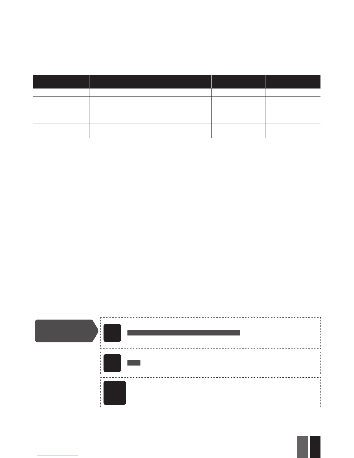
73
73
EN
ESIM384 Installation and Conguration Manual v1.1
18. PROGRAMMABLE (PGM) OUTPUTS
A PGM output is a programmable output that toggles to its set up state when a specic event has occurred in the system, the scheduled
weekday and time has come or if the user has initiated the PGM output state change manually. Normally, PGM outputs can be used to open/
close garage doors, activate lights, heating, watering and much more. When a PGM output turns ON, the system triggers any device or relay
connected to it.
ESIM384 comes equipped with four open-collector PGM outputs allowing to connect up to four devices or relays. For more details on PGM
output expanding, please refer to 18.2. PGM Output Expansion.
ESIM384 PGM outputs are classied by 4 categories:
PGM output category Description
Max. number of PGM
outputs per device
Max. number of PGM
outputs in total
On-board PGM Outputs Built-in wired PGM outputs of ESIM384 alarm system. 4 4
EPGM8 PGM Outputs
PGM outputs of EPGM8 - hardwired PGM output expansion module.
8 8
EPGM1 PGM Outputs
PGM outputs of EPGM1 - hardwired zone and PGM output
expansion module.
2 4
Wireless PGM Outputs
Non-physical PGM outputs automatically created by connected wireless devices.
2* 48**
* - Depends on the connected wireless device.
** - Available only if no EPGM1 PGM outputs are present.
For PGM output wiring diagram, please refer to 2.3.6. Relay Finder® (for example, model 40.61.9.12) with Terminal Socket (for
example, model 95.85.3).
18.1. PGM Output Numbering
The PGM output numbers ranging from C1 through C16 are permanently reserved for on-board PGM outputs even if EPGM8 module mode is
disabled. The C17-C48 PGM output number are automatically assigned in the chronological order to the devices connected to the system:
EPGM1 modules and wireless devices.
18.2. PGM Output Expansion
For additional electrical appliance connection, the number of PGM outputs can be expanded by:
• connecting EPGM8 hardwired PGM output expansion module. (for more details on technical specications and installation, please refer
to the latest user manual of the device located at www.eldesalarms.com).
• connecting EPGM1 hardwired zone and PGM output expansion module (for more details on technical specications and installation,
please refer to the latest user manual of the device located at www.eldesalarms.com).
• pairing the wireless devices (see 19. WIRELESS DEVICES).
The maximum supported PGM output number is 48.
18.2.1. EPGM8 Mode
EPGM8 is an expansion module, which expands the system with 8 additional hardwired PGM outputs. For more details on technical specications and installation, please refer to the latest user manual of the device located at www.eldesalarms.com
Once the EPGM8 module is installed, the EPGM8 mode must be enabled.
Enable EPGM8 mode
EKB2
Menu path:
OK → iiii → OK → USING EPGM8 → OK → ENABLE → OK
Value: iiii – 4-digit installer code.
EKB3/
EKB3W/
EWKB4
Enter parameter 33 and parameter status value:
33 1 #
Example: 331#
ELDES
Conguration
software
This operation may be carried out from the PC using the ELDES Conguration software.
Page 74
74
74
EN
ESIM384 Installation and Conguration Manual v1.1
Disable EPGM8 mode
EKB2
Menu path:
OK → iiii → OK → USING EPGM8 → OK → DISABLE → OK
Value: iiii – 4-digit installer code.
EKB3/
EKB3W/
EWKB4
Enter parameter 33 and parameter status value:
33 0 #
Example: 330#
ELDES
Conguration
software
This operation may be carried out from the PC using the ELDES Conguration software.
18.3. PGM Output Names
Each PGM output has a name that can be customized by the user. Typically, the name species a device type connected to a determined
PGM output, for Example: Lights. The name can be used instead of PGM output number when controlling the PGM output by SMS text
message. By default, the PGM output names are: C1 – Controll1, C2 – Controll2, C3 – Controll3, C4 – Controll4 etc.
Set PGM output name
SMS
SMS text message content:
ssss_Coo:out-name
Value: ssss – 4-digit SMS password; oo – PGM output number, range – [1... 80]; out-name –
up to 16 characters PGM output name.
Example: 1111_C2:Lights
ELDES
Conguration
software
This operation may be carried out from the PC using the ELDES Conguration software.
View PGM output
names
SMS
SMS text message content:
ssss_INFO
Value: ssss – 4-digit SMS password.
Example: 1111_STATUS
EKB2
Menu path:
OK → mmmm → OK → PGM OUTPUTS → OK → out-name
Value: mmmm – 4-digit master code; out-name – up to 16 characters PGM output name.
ELDES
Conguration
software
This operation may be carried out from the PC using the ELDES Conguration software.
ATTENTION: Space, colon, semi-colon characters, parameter names and/or values, such as PSW, STATUS, ON, OFF etc. are NOT allowed in
PGM output names.
18.4. Disabling and Enabling PGM Outputs
By default, all PGM outputs are enabled. Once a PGM output is disabled, it can be turned ON or OFF thus the change will not be seen neither
on the EKB2 keypad nor via Cloud platform. To disable/enable a certain PGM output, please refer to the following conguration method.
Disable/enable PGM
outputs
ELDES
Cong-
uration
softwarel
This operation may be carried out from the PC using the ELDES Conguration software.
18.5. Turning PGM Outputs ON and OFF
By default, all PGM outputs are turned OFF. To instantly turn ON/OFF an individual PGM output and set its state to ON/OFF when the system
starts-up, please refer to the following conguration methods.
Page 75
75
75
EN
ESIM384 Installation and Conguration Manual v1.1
Turn ON PGM output/
Set PGM output startup state as ON
SMS
SMS text message content:
ssss_Coo:ON or ssss_out-name:ON
Value: ssss – 4-digit SMS password; oo – PGM output number, range – [1... 80]; out-name –
up to 16 characters PGM output name.
Example: 1111_Lights:ON
EKB2
Menu path:
OK → mmmm → OK → PGM OUTPUTS → OK → out-name → ON → OK
Value: mmmm – 4-digit master code; out-name – up to 16 characters PGM output name.
EKB3/
EKB3W/
EWKB4
Enter parameter 61, PGM output number and parameter status value:
61 oo 1 #
Value: oo – PGM output number, range – [01... 80].
Example: 61031#
ELDES
Cong-
uration
software
This operation may be carried out from the PC using the ELDES Conguration software.
EWK1/
EWK2
This operation may be carried out from the wireless keyfob if pre-assigned using the PC running ELDES Conguration software.
Turn OFF PGM output/
Set PGM output startup state as OFF
SMS
SMS text message content:
ssss_Coo:OFF or ssss_out-name:OFF
Value: ssss – 4-digit SMS password; oo – PGM output number, range – [1... 80]; out-name –
up to 16 characters PGM output name.
Example: 1111_C2:OFF
EKB2
Menu path:
OK → mmmm → OK → PGM OUTPUTS → OK → out-name → OFF → OK
Value: mmmm – 4-digit master code; out-name – up to 16 characters PGM output name.
EKB3/
EKB3W/
EWKB4
Enter parameter 61, PGM output number and parameter status value:
61 oo 0 #
Value: oo – PGM output number, range – [01... 80].
Example: 61020#
ELDES
Conguration
software
This operation may be carried out from the PC using the ELDES Conguration software.
EWK1/
EWK2
This operation may be carried out from the wireless keyfob if pre-assigned using the PC running ELDES Conguration software.
To instantly turn ON an individual PGM output for a determined time period and automatically turn it OFF when the time period expires,
please refer to the following conguration method.
Turn ON PGM output
for time period
SMS
SMS text message content:
ssss_Coo:ON:hr.mm.sc or ssss_out-name:ON:hr.mn.sc
Value: ssss – 4-digit SMS password; oo – PGM output number, range – [1... 80]; out-name
– up to 16 characters PGM output name; hr – hours, range – [00... 23]; mn – minutes, range
– [00... 59]; sc – seconds, range – [00... 59].
Example: 1111_C4:ON:10.15.35
EWK1/
EWK2
This operation may be carried out from the wireless keyfob if pre-assigned using the PC running ELDES Conguration software.
Page 76

76
76
EN
ESIM384 Installation and Conguration Manual v1.1
To instantly turn OFF an individual PGM output for a determined time period and automatically turn it ON when the time period expires,
please refer to the following conguration method.
Turn OFF PGM output
for time period
SMS
SMS text message content:
ssss_Coo:OFF:00.00.sc or ssss_out-name:OFF:hr.mn.sc
Value: ssss – 4-digit SMS password;oo – PGM output number, range – [1... 80]; out-name
– up to 16 characters PGM output name; hr – hours, range – [00... 23]; mn – minutes, range
– [00... 59]; sc – seconds, range – [00... 59].
Example: 1111_Lights:OFF:00.00.23
EWK1/
EWK2
This operation may be carried out from the wireless keyfob if pre-assigned using the PC running ELDES Conguration software.
When the PGM output is turned ON or OFF, the system will send a conrmation by SMS text message to the user phone number that the
SMS text message was sent from.
NOTE: PGM output can be turned ON for a determined time period only when it is in OFF state
NOTE: PGM output can be turned OFF for a determined time period only when it is in ON state
NOTE: Multiple PGM outputs can be turned ON/OFF by a single SMS text message, Example: 1111_C1:ON C2:OFF Pump:ON C4:ON:00.20.25
NOTE for EWK1/EWK2: Single EWK1/EWK2 keyfob button can be congured to carry out Partition selection and Control output/Output
toggle/Output pulse actions. In such case the PGM output control action will be executed with a 3-second delay once the button is pressed and
in case it is not followed within a 3-second period by a button with arm system or disarm system action assigned.
18.6. PGM Output Control by Event and Scheduler
The PGM outputs can automatically operate when a specic event occurs in the system and/or when the scheduled weekday and time
comes.
18.6.1. PGM Output Actions and System Events
The automatic action of the determined PGM output can be set as follows:
• Turn ON – Determines whether the PGM output is to be turned ON.
• Turn OFF – Determines whether the PGM output is to be turned OFF.
• Pulse – Determines whether the PGM output is to be turned ON or OFF for a set period of time in seconds based on the PGM output
startup state set up.
The aforementioned PGM output action can be automatically carried out under the following events that have occurred in the system:
• System armed – System is armed in a determined partition ranging from Partition 1 through 4 or any partition.
• System disarmed – System is disarmed in a determined partition ranging from Partition 1 through 4 or any partition.
• Alarm begins – Alarm begins in a determined partition ranging from Partition 1 through 4 or any partition.
• Alarm stops – Alarm stops in a determined partition ranging from Partition 1 through 4 or any partition.
• Temperature falls – Temperature falls below the set MIN value of a determined temperature sensor 1-8.
• Temperature rises – Temperature rises above the set MAX value of a determined temperature sensor 1-8.
• Zone violated – A determined zone ranging from Z1 through Z80 is violated.
• Zone restored – A determined zone ranging from Z1 through Z80 is restored.
• Scheduler starts – Operates based on Start Time of a selected scheduler 1-16.
• Scheduler ends – Operates based on End Time of a selected scheduler 1-16.
• System fault occurred - A determined system fault is present (for complete list of system faults, please refer to 29. INDICATION
OF SYSTEM FAULTS).
• System fault restored - A determined system fault is restored (for complete list of system faults, please refer to 29. INDICATION
OF SYSTEM FAULTS).
The user can also set a custom text, which will be sent by SMS text message to user phone number when the automatic PGM output action
is carried out.
Page 77
77
77
EN
ESIM384 Installation and Conguration Manual v1.1
18.6.2. Schedulers
The system supports up to 16 schedulers that allow the PGM outputs to operate or automatically arm/disarm a certain partition (all partitions) according to the day of the week and time. When the scheduler, which includes the set weekday and time, is selected, the PGM
output will operate or the system will arm/disarm according to it. Each scheduler includes the following parameters:
• Always – The scheduler is not in use.
• At specied time – Determines whether weekday and time settings are enabled:
• Start Time – Determines the point in time when the PGM output or automatic arm/disarm action can be initiated for Scheduler
starts event.
• End Time – Determines the point in time when the PGM output action can be initiated for Scheduler ends event
• On weekdays – Determines days in week when the PGM output or automatic arm/disarm action is valid.
18.6.3. Additional Conditions
Additional condition narrows down the chances for a determined automatic PGM output operation to be carried out. If this feature is enabled, the PGM output will become dependent on one more system event that must be occurred prior or must occur after the aforementioned system event. The PGM output will not operate until the chain of system events meets the set values:
• System armed – System is armed in a determined partition ranging from 1 to 4 or any partition.
• System disarmed – System is disarmed in a determined partition ranging from 1 to 4 or any partition.
• Zone violated – A determined zone ranging from Z1 to Z80 is violated.
• Zone restored – A determined zone ranging from Z1 to Z80 is restored.
Example: PGM output C1 is set to be turned ON when zone Z6 is violated. The additional condition feature is enabled and set to allow this
action to be carried out only if system’s Partition 2 is disarmed. It means that the PGM output C1 will be turned ON when zone Z6 is violated,
but only if system’s Partition 2 is disarmed.
Manage PGM output
control by event &
scheduler
ELDES
Conguration
software
This operation may be carried out from the PC using the ELDES Conguration software.
ATTENTION: If the date and time are not set, the system will NOT be able to automatically control the PGM outputs. For more details on how
to set date and time, please refer to 9. DATE AND TIME.
NOTE: When both - a system event is determined and a scheduler is selected, the PGM output will operate only if the determined event has
occurred in the system during the scheduled time period.
NOTE: When PGM output action is selected as pulse, the PGM output will turn ON or turn OFF for a set period of time based on the PGM
output state set up (ON or OFF) for system startup.
18.7. Wireless PGM Output Type Denitions
• Output – Operates as normal PGM output that can be controlled by the user or automatically by event and scheduler. Normally, this
type is used for any device or relay.
• Siren – Operates as siren output that automatically activates during alarm. Typically, this type is used for bell/siren connected to EW2
wireless device.
Set output type for
individual wireless
PGM output
ELDES
Conguration
software
This operation may be carried out from the PC using the ELDES Conguration software.
Page 78

78
78
EN
ESIM384 Installation and Conguration Manual v1.1
19. WIRELESS DEVICES
ESIM384 system has a built-in wireless module for system extension capabilities. The wireless module easily allows the user to pair up to
32 ELDES-made wireless devices with the system. This includes the following:
• EWP2 – wireless PIR sensor (motion detector).
• EWP3 - wireless PIR sensor (motion detector).
• EWD2 - wireless magnetic door contact/shock sensor/ood sensor.
• EWD3 - wireless magnetic door contact/shock sensor/ood sensor.
• EWS3 – wireless indoor siren.
• EWS2 – wireless outdoor siren.
• EWK1 and EWK2/EWK2A – wireless keyfob.
• EKB3W – wireless keypad.
• EWKB4 - wireless keypad.
• EWKB5 - wireless touchpad.
• EW2 – wireless zone and PGM output expansion module.
• EWF1 - wireless smoke detector.
• EWF1CO - wireless smoke and CO detector.
• EWR2 - wireless signal repeater.
• EWM1 - wireless power socket.
For more details on technical specications and installation of the wireless devices, please refer to chapter 41.RADIO SYSTEM INSTAL
LATION AND SIGNAL PENETRATION APPENDIX 4 and the latest user manual of the wireless device located at www.eldesalarms.com
The wireless devices can operate at a range of up to 3000m (9842.6ft) range in open areas. The wireless connection is two-way and operates in one of four available channels in ISM868 non-licensed band. When Conguration software is launched, the frequency time of attempt of all NOT added wireless devices, that have frequency time of attempt higher than 10 sec, is changed to 10 sec. After Conguration
software is closed, frequency time of attempt for every individual device is changed as it was.
NOTE: In case if Remote Connection session being activated, the frequency time of attempts for every wireless device will be exactly the
same as default Test Time period, indicated below.
The communication link between the wireless device and the alarm system is constantly supervised by a congurable self-test period,
known as Test Time. When the wireless device is switched ON, it will initiate the Test Time transmission to the system within its wireless
connection range. In order to optimize battery power saving of the wireless device, the Test Time periods vary by itself while the device
is switched ON, but still unpaired. When the alarm system is switched OFF or if the wireless device is unpaired or removed the Test Time
period of the wireless device is as follows (non-customizable):
• EKB3W, EW2, EWP2, EWS2, EWS3, EWF1, EWF1CO, EWM1:
• First 360 attempts after the device startup (reset) - every 10 seconds.
• The rest of attempts - every 1 minute.
• EWD2:
• First 360 attempts after the device startup (reset) - every 10 seconds.
• The rest of attempts - every 2 minutes.
• NOTE: Only for EWD3, EWKB4, EWP3
• Standard Test Time of all attempts when paired with alarm system - EWP3 - every 1 minute; EWKB4, EWD3 - every 5 minutes.
• Standard Test Time of all attempts when NOT paired with alarm system or in case wireless connection is lost for more than 48
hours - every 10 minutes.
Once the wireless device is paired, it will attempt to exchange data with ESIM384 system. Due to battery saving reasons, all ELDES wireless
devices operate in sleep mode. The data exchange will occur instantly if the wireless device is triggered (zone alarm or tamper alarm) or
periodically when the wireless device wakes up to transmit the supervision signal, based on Test Time value, to the system as well as to accept the queued up command (if any) from the system. By increasing the Test Time period, EWS2/EWS3 siren response time will decrease.
Example: The alarm occurred at 09:15:25 and the system queued up the command for EWS3 siren to start sounding. By default, Test Time
value of EWS3 siren is 7 seconds, therefore EWS2 siren will sound at 09:15:32.
By default, the Test Time period is as follows (customizable):
• EWKB4, EWD3: every 5 minutes.
• EKB3W, EWD2, EWP2, EWP3: every 60 seconds.
• EWM1, EW2, EWF1, EWF1CO: every 30 seconds.
• EWS2, EWS3: every 7 seconds.
To set a dierent Test Time value, please refer to the following conguration method.
Set custom Test Time
ELDES
Cong-
uration
software
This operation may be carried out from the PC using the ELDES Conguration software.
NOTE: Test Time aects the wireless device pairing process due to the alarm system listening for the incoming data from the wireless device.
The system pairs with the wireless device only when the rst data packet is received.
Page 79
79
79
EN
ESIM384 Installation and Conguration Manual v1.1
NOTE for EKB3W/EWKB4: In comparison with other ELDES wireless devices, EKB3W/EWKB4 keypads features some exceptions regard-
ing the wireless communication. For more details on EKB3W/EWKB4 keypad wireless communication and back-light timeout, please refer to
19.5.3. Wireless Communication, Sleep Mode and Back-light Timeout.
19.1. Pairing, Removing and Replacing Wireless Device
Wireless device management can be easily and conveniently carried out using the graphical interface of ELDES Conguration soft ware. If
you intend to manage the wireless devices by SMS text massage, an 8-character wireless device ID code will be required in order to pair the
device with the system or to remove it from the system. The wireless ID code is printed on a label, which can be located on the inner or outer
side of the enclosure or on the printed circuit board (PCB) of the wireless device.
To pair a wireless device, please refer to the following conguration methods.
Pair wireless device
with the system
SMS
SMS text message content:
ssss_SET:wless-id
Value: ssss – 4-digit SMS password; wless-id – 8-character wireless device ID code.
Example: 1111_SET:5353185D
ELDES
Conguration
software
This operation may be carried out from the PC using the ELDES Conguration software.
NOTE FOR EWK1/EWK2/EWK2A: When paring EWK1/EWK2/EWK2A wireless keyfob, it is necessary to press several times any button
on the device.
Once a wireless device is paired, it occupies one of 32 available wireless device slots and the system adds single or multiple wireless zones
and wireless PGM outputs depending on the wireless device model (excepting wireless keyfobs EWK1/EWK2).
To remove a wireless device, please refer to the following conguration methods.
Remove wireless
device from the
system
SMS
SMS text message content:
ssss_DEL:wless-id
Value: ssss – 4-digit SMS password; wless-id – 8-character wireless device ID code.
Example: 1111_DEL:535185D
ELDES
Conguration
software
This operation may be carried out from the PC using the ELDES Conguration software.
Once a wireless device is removed from the system, please restore its default parameters and remove the batteries from it.
To replace an existing wireless device with a new same model device, please refer to the following conguration method.
Replace wireless
device
SMS
SMS text message content:
ssss_REP:wless-id<oldwl-id
Value: ssss – 4-digit SMS password; wless-id – 8-character wireless device ID code of the new
devi ce; oldwl-id - 8-character wireless device ID code of the old device.
Example: 1111_REP:535185D<41286652
When a wireless device is successfully replaced with a new one, the conguration of the old wireless device remains.
ATTENTION: In order to correctly remove the wireless device from the system, the user must remove the device using SMS text message or
ELDES Conguration software and restore the parameters of the wireless device to default afterwards. If only one of these actions is carried
out, the wireless device and the system will attempt to exchange data to keep the wireless connection alive. This leads to fast battery power
drain on the battery-powered wireless device.
NOTE: If you are unable to pair a wireless device, please restore the wireless device’s parameters to default and try again. For more details on
how to restore the default parameters, please refer to the user manual provided along with the wireless device or visit
www.eldesalarms.com to download the latest user manual.
Page 80
80
80
EN
ESIM384 Installation and Conguration Manual v1.1
19.2. Wireless Device Information
Once a wireless device is paired, the user can view the following information of a determined wireless device:
• Battery level (expressed in percentage).
• Wireless signal strength (expressed in percentage).
• Error rate (number of failed data transmission attempts in 10-minute period) - indicated only in EKB2 keypad menu.
• Firmware version.
• Test Time period (expressed in milliseconds) of a wireless device - indicated only in SMS text message reply.
To view the wireless device information, please refer to the following conguration methods.
View wireless device
information
SMS
SMS text message content:
ssss_RFINFO:wless-id or ssss_RFINFO:Znn
Value: ssss – 4-digit SMS passwordwless-id – 8-character wireless device ID code; nn –
wireless zone number, range – [13... 80].
Example: 1111_RFINFO:535185D
EKB2
Menu path:
Battery level: OK → iiii → OK → WIRELESS DEVICES 1... 2→ OK → wless-dev wless-id → OK
→ BATTERY
Wireless signal: ... → wless-dev wless-id → OK → SIGNAL
Error rate: ... → wless-dev wless-id → OK → ERROR RATE
Firmware version: ... → wless-dev wless-id → OK → FW RELEASE
Value: iiii – 4-digit installer code; wless-dev – wireless device model; wless-id – 8-character
wireless device ID code.
ELDES
Conguration
software
This operation may be carried out from the PC using the ELDES Conguration software.
The system supports up to 32 wireless devices. To view the number of available wireless device slots in the system, please refer to the
following conguration methods
View available
wireless device slots
SMS
SMS text message content:
ssss_STATUS_FREE
Value: ssss – 4-digit SMS password.
Example: 1111_STATUS_FREE
ELDES
Conguration
software
This operation may be carried out from the PC using the ELDES Conguration software.
19.3. Wireless Signal Status Monitoring
If the wireless signal is lost due to poor signal strength or low battery power on a certain wireless device and does not restore within
4-hour period, the system will cause an alarm (by default, the alarm is disabled). This event is identied as Wireless Signal Loss. By default,
indicated as No wireless signal from wless-dev wless-id Tamper x in the SMS text message (wless-dev = wireless device model; wless-id =
8-character wireless device ID code; x = tamper number). The user will also be notied by SMS text message as soon as the wireless signal
is restored.
The default period for wireless signal loss detection is 4 hours. However, a custom wireless signal loss timeout can be set up that must be
at least 3 times longer than the longest Test Time period of a wireless device currently paired with the system. In addition, ELDES Congu-
ration software indicates a timer of the last Test Time signal delivered by a paired and unpaired wireless device. The software will also warn
you if the delivery of the Test Time signal is delayed for a time period that is 5 minutes longer than the Test Time period of a paired wireless
device. In case the Test Time signal delivery of an unpaired wireless device is delayed for more than 1,5 minute, a warning will follow and
the icon of such wireless device will be removed from the software’s interface in 10 seconds.
Manage
Grade2 wireless
communication
settings
ELDES
Conguration
soft-
ware
This operation may be carried out from the PC using the ELDES Conguration software.
Page 81

81
81
EN
ESIM384 Installation and Conguration Manual v1.1
Disable wireless
signal loss/restore
notication
EKB2
Menu path:
User phone number: OK → iiii → OK → SMS MESSAGES 2 → OK → WLESS SIGN LOSS EV → OK
→ GSM USER 1... 10 → OK → DISABLE → OK
SMS text message to all users simultaneously: ... → WLESS SIGN LOSS EV → OK → SMS TO ALL →
OK → DISABLE → OK
SMS delivery report: ... → WLESS SIGN LOSS EV → OK → SMS REPORT → OK → DISABLE → OK
Value: iiii – 4-digit installer code.
EKB3/
EKB3W/
EWKB4
Enter parameter 25/21/55, event number, user phone number slot and parameter
status value:
User phone number: 25 18 up 0 #
SMS text message to all users simultaneously: 21 18 0 #
SMS delivery report: 55 18 0 #
Value: up - user phone number slot, range - [01... 10].
Example: 2518030#
ELDES
Conguration
software
This operation may be carried out from the PC using the ELDES Conguration software.
Enable wireless
signal loss/restore
notication
EKB2
Menu path:
User phone number: OK → iiii → OK → SMS MESSAGES 2 → OK → WLESS SIGN LOSS EV → OK
→ GSM USER 1... 10 → OK → ENABLE → OK
SMS text message to all users simultaneously: ... → WLESS SIGN LOSS EV → OK → SMS TO ALL
→ OK → ENABLE → OK
SMS delivery report: ... → WLESS SIGN LOSS EV → OK → SMS REPORT → OK → ENABLE → OK
Value: iiii – 4-digit installer code.
EKB3/
EKB3W/
EWKB4
Enter parameter 25/21/55, event number, user phone number slot and parameter
status value:
User phone number: 25 18 up 1 #
SMS text message to all users simultaneously: 21 18 1 #
SMS delivery report: 55 18 1 #
Value: up - user phone number slot, range - [01... 10].
Example: 2518031#
ELDES
Conguration
software
This operation may be carried out from the PC using the ELDES Conguration software.
Enable wireless
communication failed
notication
EKB2
Menu path:
User phone number: OK → iiii → OK → SMS MESSAGES 2 → OK → WRLESS FAIL 20MIN. → OK
→ GSM USER 1... 10 → OK → ENABLE → OK
SMS text message to all users simultaneously: ... → WRLESS FAIL 20MIN. → OK → SMS TO ALL
→ OK → ENABLE → OK
SMS delivery report: ... → WRLESS FAIL 20MIN. → OK → SMS REPORT → OK → ENABLE → OK
Value: iiii – 4-digit installer code.
EKB3/
EKB3W
Enter parameter 25/21/55, event number, user phone number slot and parameter
status value:
User phone number: 25 25 up 1 #
SMS text message to all users simultaneously: 21 25 1 #
SMS delivery report: 55 25 1 #
Value: up - user phone number slot, range - [01... 10].
Example: 2525031#
ELDES
Conguration
software
This operation may be carried out from the PC using the ELDES Conguration software.
Page 82
82
82
EN
ESIM384 Installation and Conguration Manual v1.1
Disable wireless
communication failed
notication
EKB2
Menu path:
User phone number: OK → iiii → OK → SMS MESSAGES 2 → OK → WRLESS FAIL 20MIN. → OK
→ GSM USER 1... 10 → OK → DISABLE → OK
SMS text message to all users simultaneously: ... → WRLESS FAIL 20MIN. → OK → SMS TO ALL →
OK → DISABLE → OK
SMS delivery report: ... → WRLESS FAIL 20MIN. → OK → SMS REPORT → OK → DISABLE → OK
Value: iiii – 4-digit installer code.
EKB3/
EKB3W
Enter parameter 25/21/55, event number, user phone number slot and parameter
status value:
User phone number: 25 25 up 0 #
SMS text message to all users simultaneously: 21 25 0 #
SMS delivery report: 55 25 0 #
Value: up - user phone number slot, range - [01... 10].
Example: 252530#
ELDES
Cong-
uration
software
This operation may be carried out from the PC using the ELDES Conguration software.
ATTENTION: Once a certain tamper is disabled, the system will NOT deliver any SMS text message regarding the physical tamper violation
nor wireless signal loss or restore. For more details on how to manage the tampers, please refer to 16. TAMPERS.
ATTENTION: The system will NOT deliver any text message regarding wireless signal loss or restore while the physical tamper violation is in
progress.
Page 83
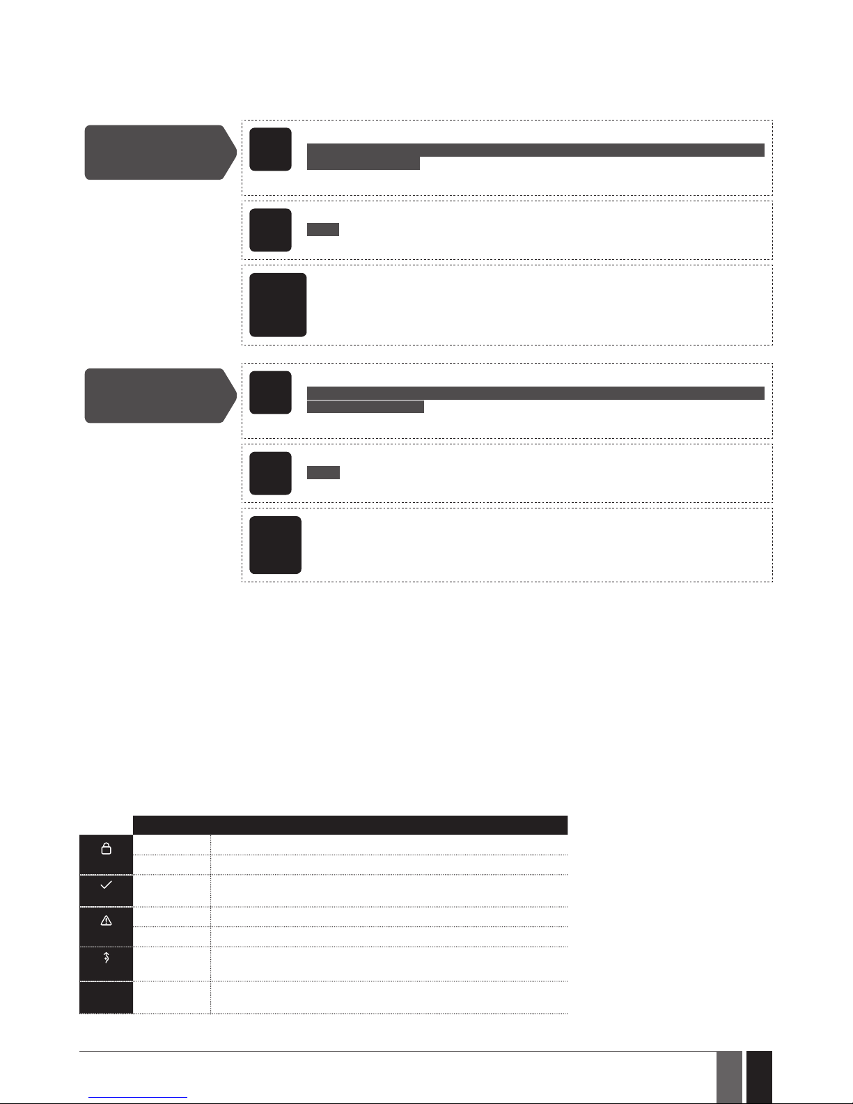
83
83
EN
ESIM384 Installation and Conguration Manual v1.1
19.4. Disabling and Enabling Siren if Wireless Signal is Lost
If a wireless device loses its wireless signal for 4-hour (by default) or longer, the system will send notication by SMS text message to user
phone number and activate the siren/bell. By default, the siren will not be activated when wireless signal is lost. To enable/disable this
feature, please refer to the following conguration methods.
Enable Siren if
Wireless Signal is Lost
EKB2
Menu path:
OK → iiii → OK → PRIMARY SETTINGS → OK → SIREN SETTINGS →OK → SRN IF WLESS LOSS
→ OK → ENABLE → OK
Value: iiii – 4-digit installer code.
EKB3/
EKB3W/
EWKB4
Enter parameter 76 and parameter status value:
76 1 #
Example: 761#
ELDES
Cong-
uration
software
This operation may be carried out from the PC using the ELDES Conguration software.
Disable Siren if
Wireless Signal is Lost
EKB2
Menu path:
OK → iiii → OK → PRIMARY SETTINGS → OK → SIREN SETTINGS →OK → SRN IF WLESS LOSS
→ OK → DISABLE → OK
Value: iiii – 4-digit installer code.
EKB3/
EKB3W/
EWKB4
Enter parameter 76 and parameter status value:
76 0 #
Example: 760#
ELDES
Conguration
software
This operation may be carried out from the PC using the ELDES Conguration software.
19.5. EKB3W/EWKB4 - Wireless LED Keypad
Main features:
• Alarm system arming and disarming (see 12.5. EKB3W/EWKB4 Keypad and User/Master Code).
• Arming and disarming in Stay mode (see 15. STAY MODE).
• System parameter conguration (see 5. CONFIGURATION METHODS).
• PGM output control (see 18.4. Turning PGM Outputs ON and OFF).
• Visual indication by LED indicators (see 19.5.1. LED Functionality).
• Audio indication by built-in buzzer.
• Keypad partition switch (see 23.3. Keypad Partition and Keypad Partition Switch).
For more details on technical specications and installation, please refer to the latest user manual of the device located at
www.eldesalarms.com
19.5.1. LED Functionality
INDICATION DESCRIPTION
(red)
Steady ON System armed / exit delay in progress
Flashing Conguration mode activated
(green)
Steady ON System is ready – no violated zones and/or violated tampers exist
(orange)
Steady ON System faults exist
Flashing Violated high-numbered zone
(orange)
Steady ON Violated zone bypassed
112
(red)
Steady ON Zone violated / conguration command being typed in
Page 84
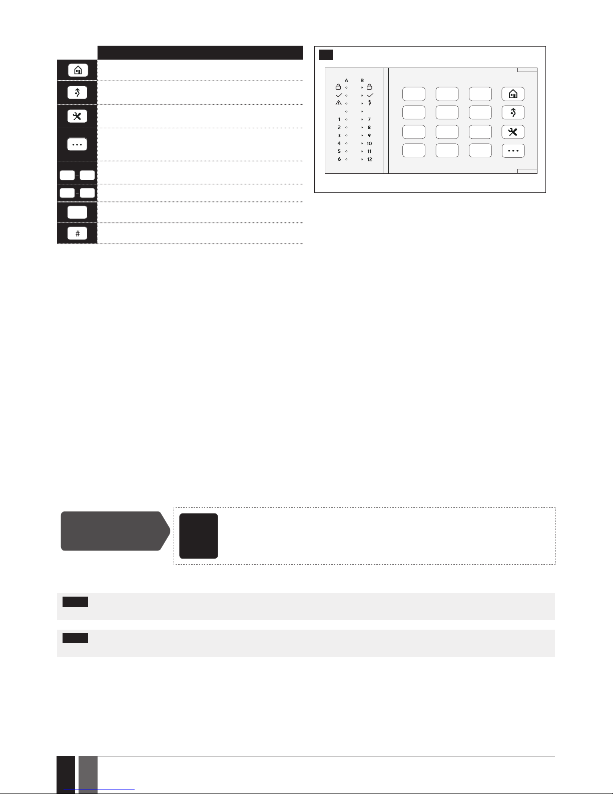
84
84
EN
ESIM384 Installation and Conguration Manual v1.1
19.5.2. Keys Functionality
DESCRIPTION
1 2 3
4 5 6
7 8 9
*
0 #
40
FRONT SIDE
1st character for STAY-arming
1st character for violated zone bypass and bypassed
zone activation
1st character for Configuration mode activation or
deactivation
1st character for system fault list indication / 1st
character for violated high-numbered zone indication
/ 1st character for violated tamper indication
0
9
Command typing
1 2
Keypad partition switch
*
Clear typed in characters
Typed in command confirmation
19.5.3. Wireless Communication, Sleep Mode and Back-light Timeout
Once the wireless device is paired, it will attempt to exchange data with ESIM384 system. The communication process follows this pattern:
1. Due to battery power saving reasons, most of the time EKB3W/EWKB4 keypad operates in sleep mode and periodically wakes up (by
default - every 5 minutes) to transmit the supervision signal, identied as Test Time, to the ESIM384 system. However, when the keypad
wakes up, it will NOT activate its buzzer and/or the LED indicators.
2. When any EKB3W/EWKB4 key is pressed, the keypad LED indicators and the back-light will activate for a set up period of time (by default 10 seconds), identied as Back-light Timeout. During the Back-light Timeout, the Test Time will automatically switch to 2 seconds period
allowing to indicate system alarms, faults and arm/disarm process on the EKB3W/EWKB4 keypad if it is assigned to the same partition as
the one that is violated or being armed/disarmed (see 23. PARTITIONS).
3. The Back-light timeout will expire after 10 seconds (by default) of EKB3W/EWKB4 idling. When the Back-light Timeout expires, the keypad will light OFF the LED indicators and the back-light and return to sleep mode. Meanwhile:
a) if a zone or tamper, which is of the associated EKB3W/EWKB4 keypad, is violated, EKB3W/EWKB4 will instantly wake up and initiate
the Back-light Timeout. Meanwhile the keypad buzzer will emit short beeps and the LED indicators will light ON indicating the violated
zone or tamper number.
b) if a zone or tamper, which is not of the associated EKB3W/EWKB4 keypad, is violated, EKB3W/EWKB4 keypad will NOT wake up and will
NOT initiate the Back-light Timeout as well as the buzzer will NOT emit short beeps and the LED indicators will NOT light ON.
To set a dierent Back-light Timeout value, please refer to the following conguration method:
Set Back-light
Timeout
ELDES
Conguration
software
This operation may be carried out from the PC using the ELDES Conguration software.
For more details and how to set a dierent Test Time value, please refer to ELDES Conguration software.
NOTE: By default, the keypad zone and tamper is enabled, therefore a resistor supplied with the EKB3W/EWKB4 keypad must be connect-
ed to the keypad zone terminal and the tamper switch must be properly pressed in when inserting the keypad into the holder.
NOTE: To wake up the keypad it is highly recommended to press the [*] key in order not to enter any unnecessary character. If other
character is pressed it is already counted in characters sequence meant for arming/disarming or conguration.
Page 85
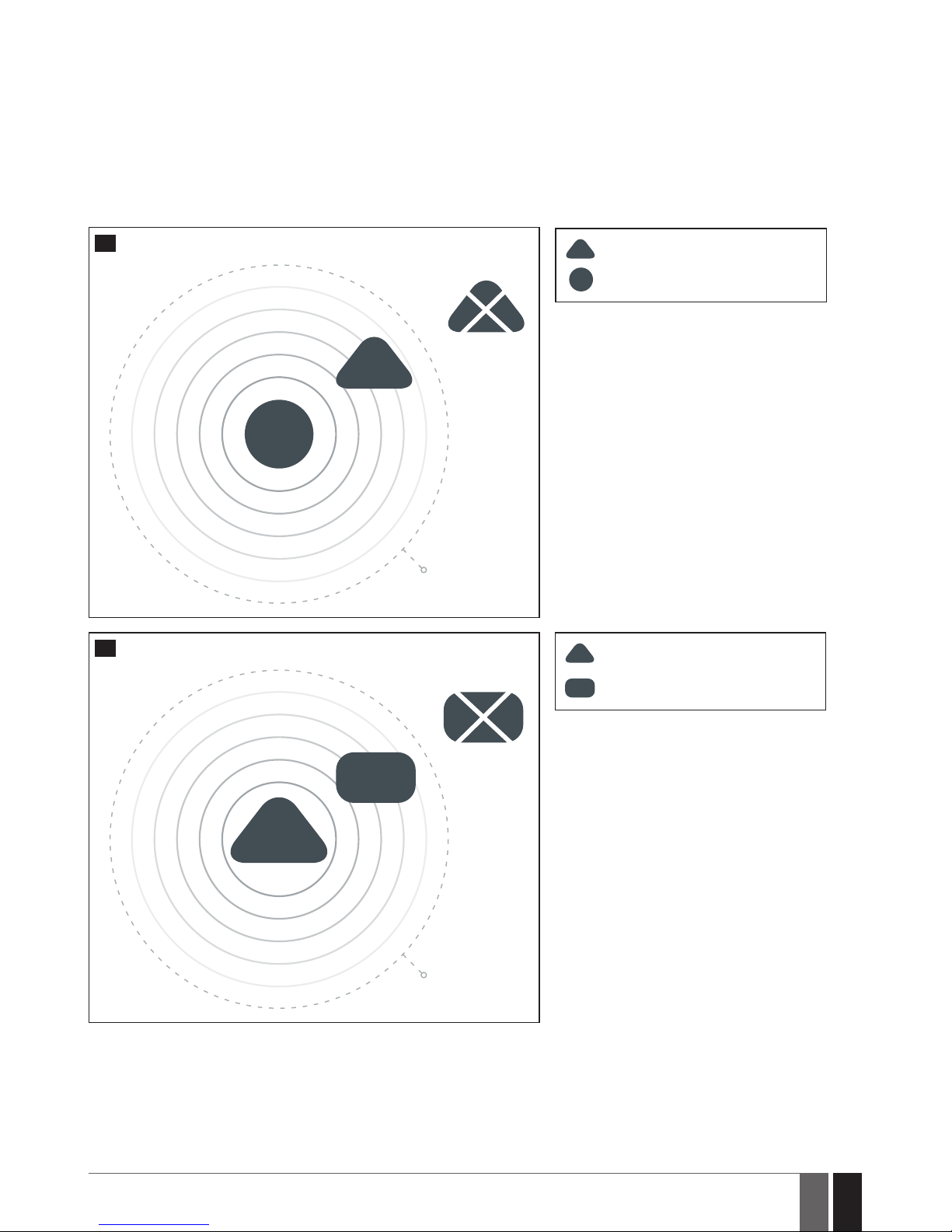
85
85
EN
ESIM384 Installation and Conguration Manual v1.1
19.6. EWR2 – Wireless Signal Repeater
Main features:
• Expands the wireless signal range (up to 30m (98.43ft) in premises; up to 150m (492.13ft) in open areas)
• LED indicator for data transmission indication.
• External and internal antenna.
• Backup battery
For more details on technical specications and installation, please refer to the latest user manual of the device located at
www.eldesalarms.com
ALARM
SYSTEM
W-less signal
Level 18%
EWR2
EWR2
G
o
o
d
s
i
g
n
a
l
l
e
v
e
l
B
a
d
s
i
g
n
a
l
l
e
v
e
l
41
EWR2 begins expanding the signal range for
wireless devices if the certain conditions are
met. In order for EWR2 to function properly,
the wireless signal level between EWR2 and
ELDES alarm system must be at least 40%.
EWR2
EWR2
ALARM
SYSTEM
Wireless signal repeater
ELDES alarm system
EWR2
EWR2
ALARM
SYSTEM
WIRELESS
DEVICE
Wireless signal repeater
Wireless device
W-less signal
Level 18%
EWR2
G
o
o
d
s
i
g
n
a
l
l
e
v
e
l
B
a
d
s
i
g
n
a
l
l
e
v
e
l
WIRELESS
DEVICE
WIRELESS
DEVICE
42
In order for EWR2 to start expanding the signal range of a wireless device, the wireless
signal level between EWR2 and a wireless
device must be at least 18%.
Page 86
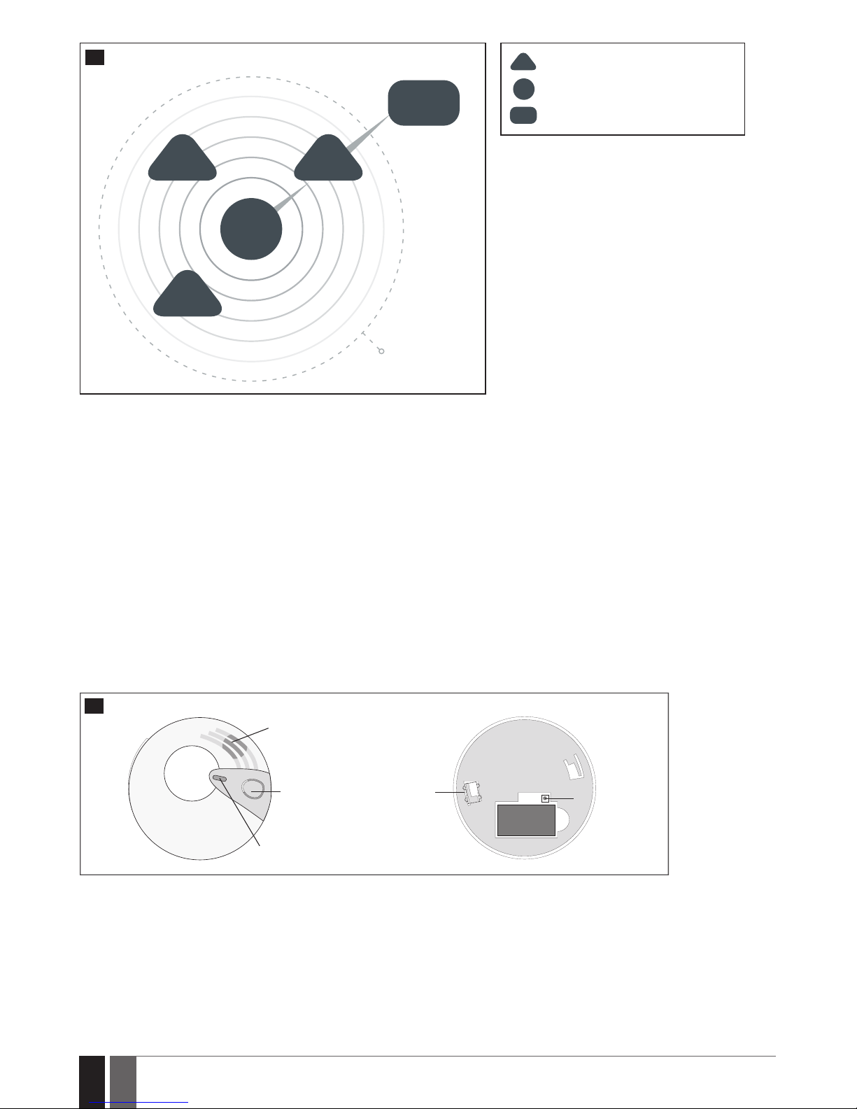
86
86
EN
ESIM384 Installation and Conguration Manual v1.1
W-less signal
Level 18%
EWR2
EWR2
G
o
o
d
s
i
g
n
a
l
l
e
v
e
l
B
a
d
s
i
g
n
a
l
l
e
v
e
l
ALARM
SYSTEM
WIRELESS
DEVICE
EWR2
43
If more then one repeater is connected to Eldes
alarm system at a time, the one that receives the
strongest signal from a wireless device, will be used
to expand it’s signal range. New generation wireless
devices are not able to use repeater for boosting
their signal.
EWR2
EWR2
ALARM
SYSTEM
EWR2
ALARM
SYSTEM
WIRELESS
DEVICE
Wireless signal repeater
Wireless device
ELDES alarm system
19.7. EWF1/EWF1CO - Wireless Smoke/CO Detector
Main features:
• Photoelectricsensorforslowsmoulderingres
• Photoelectric Co sensor for slow smouldering res and carbon monoxide (CO) gas detection
• TESTbutton
• Non-radioactivetechnologyforenvironmentalfriendly
• Highandstablesensitivity
• Quickxmountingplateforeasyinstallation
• LEDoperationindicator
• Built-inspeakerforaudioalarmindication
• Auto-resetwhensmoke/COclears
For more details on technical specications and installation, please refer to the latest user manual of the device located at
www.eldesalarms.com
BACK SIDE
RESET button
BATTERY
SIREN
TEST button
LED indicator
D
O
N
O
T
P
A
I
N
T
FRONT SIDE
TAMPER
switch
44
19.7.1. Interconnection
The interconnection feature automatically links all wireless smoke/CO detectors that are paired with the alarm system. When any EWF1/
EWF1CO detects smoke or carbon monoxide (CO), it will sound the built-in siren and send the signal to the alarm system resulting in an instant alarm followed by built-in siren sound caused by the rest of EWF1/EWF1CO wireless smoke/CO detectors. EWF1/EWF1CO device that
detected smoke/CO will auto-reset when the smoke/CO clears, while the rest of EWF1/EWF1CO smoke/CO detectors will continue to sound
in accordance with the set time period (by default - 30 seconds).
By default, the interconnection feature is enabled and the siren alarm duration is 30 seconds. To manage these parameters, please refer
to the following conguration methods.
Page 87
87
87
EN
ESIM384 Installation and Conguration Manual v1.1
Disable
interconnection
EKB2
Menu path:
OK → iiii → OK → PRIMARY SETT INGS → OK → SIREN SETTINGS → OK → EWF1 SIREN INTERC.
→ OK → DISABLE → OK
Value: iiii – 4-digit installer code.
EKB3/
EKB3W/
EWKB4
Enter parameter 50 and parameter status value:
50 0 #
Example: 500#
ELDES
Cong-
uration
software
This operation may be carried out from the PC using the ELDES Conguration software.
Enable
interconnection
EKB2
Menu path:
OK → iiii → OK → PRIMARY SETT INGS → OK → SIREN SETTINGS → OK → EWF1 SIREN INTERC.
→ OK → ENABLE → OK
Value: iiii – 4-digit installer code.
EKB3/
EKB3W/
EWKB4
Enter parameter 50 and parameter status value:
50 1 #
Example: 501#
ELDES
Conguration
software
This operation may be carried out from the PC using the ELDES Conguration software.
Set EWF1/EWF1CO
siren alarm duration
ELDES
Cong-
uration
software
This operation may be carried out from the PC using the ELDES Conguration software.
NOTE: The maximum supported EWF1/EWF1CO siren alarm duration is 255 seconds (4 mins. 15 secs.) even if the system‘s alarm duration value
is longer.
NOTE: System‘s alarm duration has a higher priority against the EWF1/EWF1CO siren alarm duration, therefore EWF1/EWF1CO will sound
as long as the system‘s alarm duration set up, unless the set up value for EWF1/EWF1CO siren alarm duration is shorter.
Page 88
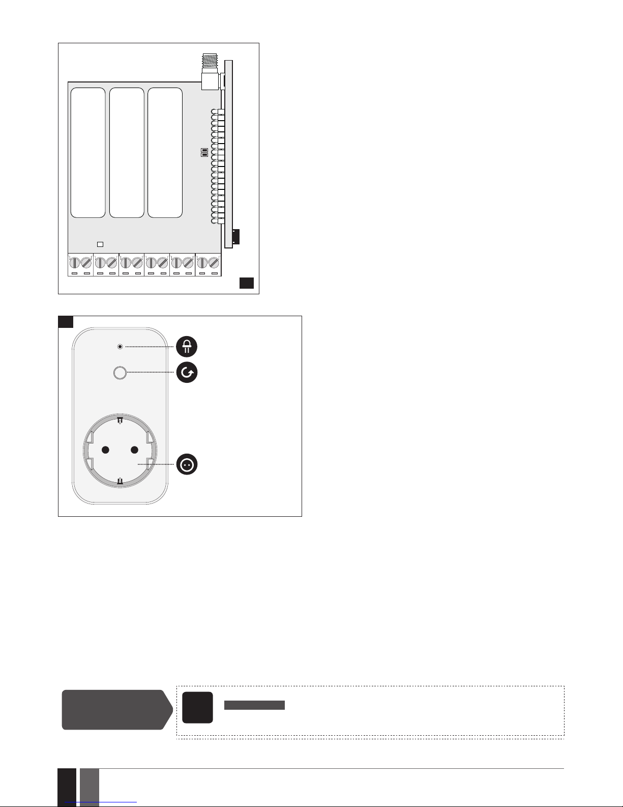
88
88
EN
ESIM384 Installation and Conguration Manual v1.1
19.8. EW2 - Wireless Zone and PGM Output Expansion Module
BATTERY
-
+
BATTERY
-
+
BATTERY
-
+
RESET
STATUS
POWER
ANT
Z1 Z2 Z3 Z4 T1 T2 C1 C2COM COM COMDC+
RESET
F1
45
Main features:
• 4zoneterminals.
• 2open-collectoroutputs.
• Batteryorexternally-powered.
• Compatiblewithanythird-partywiredsensororsiren.
EW2 is a wireless device intended to expand ELDES alarm system capabilities
by providing wireless connection access to any third-party wired devices. EW2
comes equipped with 4 zone terminals designed for wired digital sensor connection, such as magnetic door contact, motion detector etc. In addition, the 2
open-collector outputs on board allow to connect any wired siren as well as to
connect and control any electrical appliance, such as gates, lights, watering etc.
The device can operate by powering it either using an external power supply or
3 x 1,5V AA type alkaline batteries on board. Once the external power supply is
disconnected, EW2 will automatically switch to battery power.
The maximum number of EW2 devices that can be paired with the system depends on the number of the existing zones in system’s conguration. In case no
keypad zones, no EPGM1 zones, no virtual zones and no other wireless zones
exist, the system will support up to 16 EW2 devices.
For more details on technical specications and installation, please refer to the
latest user manual of the device located at www.eldesalarms.com
19.9. EWM1 - Wireless Power Socket
LED indication
Type E, F
or G outlet
Button for
restoring default
parameters or
turning ON/OFF
EWM1 when
paired with ELDES
alarm system
46
Main features:
• Control your household equipment remotely by wireless keyfob,
keypad, ELDES Cloud Services or automatically by scheduled time
or system event
• Compatible with any 230V electrical appliance
• View real-time, daily and monthly power consumption report
• Fault indication and protection: circuit thermal, overvoltage, over-
current, undervoltage, relay fault indication.
EWM1 is a wireless device intended to expand ELDES alarm system capabilities by providing a wireless connection access to any 230V
electrical appliance, such as lights, air-conditioner, watering equipment etc. By plugging the appliance into the electrical outlet of EWM1,
the user gains a possibility to control it by wireless keyfob, keypad, scheduled time or a specic system event. In addition, EWM1 lets you
monitor the power consumption and view the reports. In addition, the for safety and protection purposes EWM1 will prevent from powering
up the electrical appliance if certain fault conditions are present (see 29. INDICATION OF SYSTEM FAULTS) In order to start using EWM1,
it has to be paired with ELDES alarm system using ELDES Conguration software or by sending a corresponding SMS text message to ELDES
alarm system.
It is possible to pair up to 32 EWM1 devices with the system at a time.
The maximum wireless connection range is 150m (492.13ft) (in open areas).
For more details on technical specications and installation, please refer to the latest user manual of the device located at:
www.eldesalarms.com
To monitor real-time power consumption value , view today’s or monthly power consumption reports or reset the power consumption
counter, please refer to the following conguration methods.
View power
consumption reports
SMS
SMS text message content:
ssss_EWM1INFO
Value: ssss - 4-digit SMS password.
Example: 1111_EWM1INFO
Page 89
89
89
EN
ESIM384 Installation and Conguration Manual v1.1
EKB2
Menu path:
Real-time power consumption: OK → mmmm → OK → PGM OUTPUTS → OK → out-name →
OK → REAL TIME ENERGY
Today’s power consumption: ... → out-name→ OK → TODAY ENERGY
Monthly power consumption: ... → out-name → OK → MONTHLY ENERGY
Value: mmmm – 4-digit master code; out-name - PGM output name associated with a
certain EWM1 device.
ELDES
Cong-
uration
software
This operation may be carried out from the PC using the ELDES Conguration software.
Reset power
consumption counter
for individual EWM1
device
SMS
SMS text message content:
ssss_EWM1RESET:out-name
Value: ssss - 4-digit SMS password; out-name - PGM output name associated with a certain
EWM1 device.
Example: 1111_EWM1RESET:Controll14
EKB2
Menu path:
OK → mmmm → OK → PGM OUTPUTS → OK → out-name → OK → RESET COUNTER → OK →
YES → OK
Value: mmmm – 4-digit master code; out-name - PGM output name associated with a
certain EWM1 device.
ELDES
Conguration
software
This operation may be carried out from the PC using the ELDES Conguration software.
Reset power
consumption counter
for all EWM1 devices
simultaneously
SMS
SMS text message content:
ssss_EWM1RESET:ALL
Value: ssss - 4-digit SMS password.
Example: 1111_EWM1RESET:ALL
NOTE: Real-time power consumption value is NOT included in the power consumption report requested by SMS text message and can only
be seen on Eldes Cloud.
19.10. EWKB5 Wireless Touchpad Overview
EWKB5 is a wireless accessory equipped with a 4.3” true-colour touch screen and compatible with ESIM384 alarm system.
device features:
• Arming and disarming
• Violated zone bypass and bypassed zone activation
• PGM output control
• Customizable user-friendly graphical menu
• Navigation through the menu using the touch screen
• Multilingual voice-guided audio instructions
• Adjustable brightness and volume level
• Battery or externally-powered
• Add/delete/edit username and user/master code PIN (accessi-
ble from the User’s menu)
EWKB5 has 1 built-in zone terminal, which is by default designed for passive wired digital sensor connection, such as magnetic door contact, and 2 tamper switches for enclosure state supervision in case it is illegally opened or detached from the wall. Regardless if the tamper
switch alone is to be used, the zone must be enabled and the resistor of 5,6k nominal must be connected across Z1 and COM connectors.
It is possible to connect up to 4 EWKB5 devices to the alarm system ESIM384. The maximum wireless connection range is 1000m (~984ft)
(in open areas).
Main menu features:
Partition button – arms/disarms the system once a valid master/user code PIN is entered; indicates partition status (armed/disarmed),
presence of system faults.
Quick arm button – arms the system by touching and holding this button; master/user code not required (customizable, hidden by default;
not shown in picture).
Bypass - the Bypass icon will be shown on the main screen if any bypassed zone is present.
Fire – instantly causes re alarm by pressing and holding this button (customizable, hidden by default).
Panic – instantly causes silent alarm by pressing and holding this button (customizable, hidden by default).
Controls – opens PGM output menu, thus letting you turn a certain PGM output ON or OFF (customizable, hidden by default).
Settings – grants access to settings menu once a valid master code is entered.
Page 90
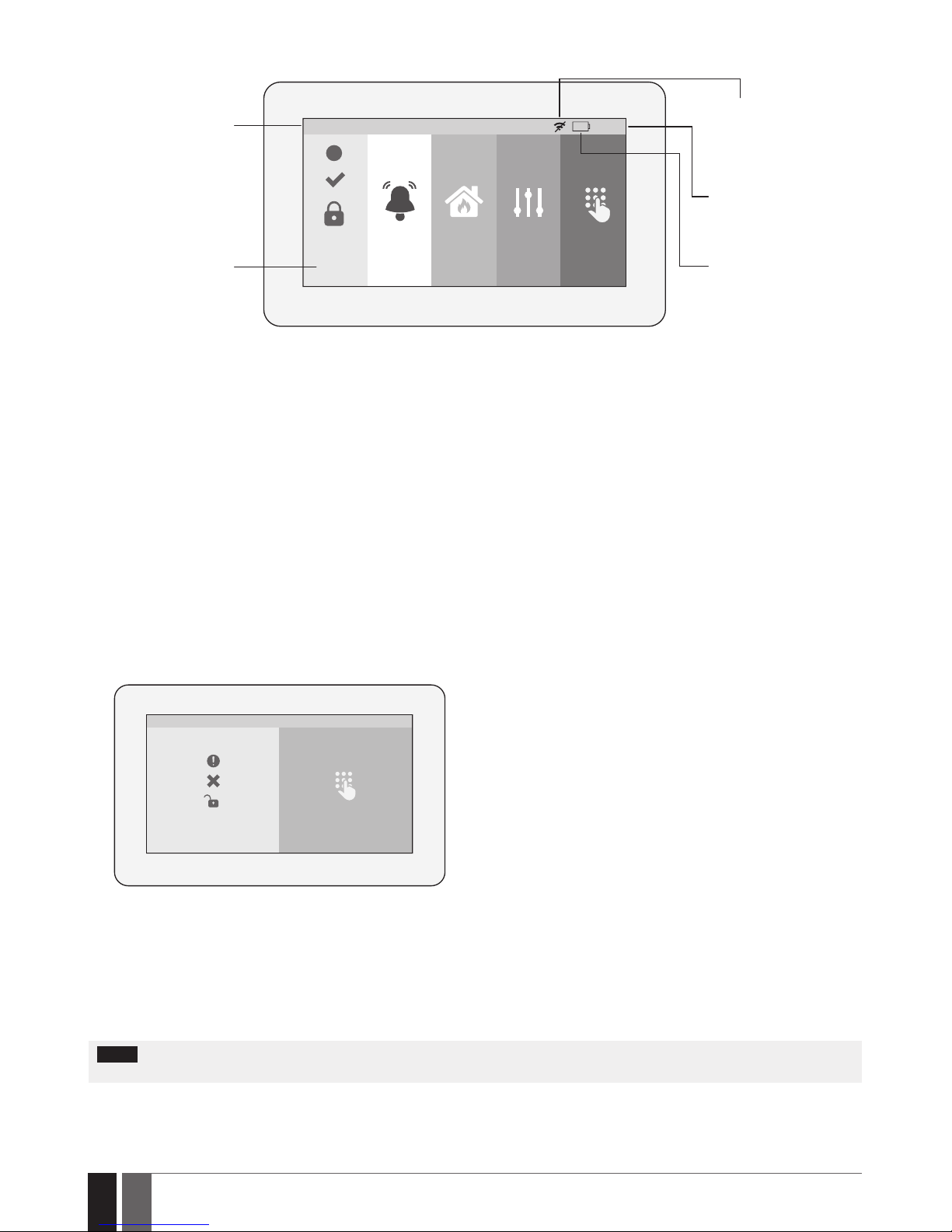
90
90
EN
ESIM384 Installation and Conguration Manual v1.1
HOME: 27 oC
HOME Panic Fire Controls Settings
01:19
!
Digital
clock
Low
battery
Low wireless
signal
Temperature
Partition
button
Dashboard features:
• Low wireless signal – appears when the wireless signal strength ( between EWKB5 and alarm system) drops below 30%.
• Low battery – appears when the battery power drops below 5%.
• Temperature – measured by a built-in ESIM384 temperature sensor or a wireless device paired with the system (customizable, disabled
and hidden by default)
• Digital clock – displays system’s current time.
19.10.1. Sleep mode and how to wake up EWKB5
Once EWKB5 is paired, it will attempt to exchange data with the system. The communication process follows this pattern:
Sleep mode. Due to battery power saving reasons, most of the time EWKB5 touchpad operates in sleep mode and periodically (by default
– every 30 seconds) transmits the supervision signal, identied as Test Time, to the ESIM384 system. When the touchpad operates in the
sleep mode, the LCD display is switched OFF, but the touchpad permanently stays alert in case of alarm event. However, when the touchpad
transmits the supervision signal to the system, it will NOT activate the LCD display.
How to wake up EWKB5
Home
Settings
01:19
V0.0
The touchpad will instantly wake up and activate the LCD display under the following conditions:
• when the user slide his nger across the LCD display.
• in the event of any type of alarm while the partition is being armed.
• in the event of re alarm, regardless of the system status – armed or disarmed.
• while entry delay countdown is in progress.
NOTE: It is highly recommended installing EWKB5 near the designated entrance/exit door and using EWKB5 zone for wired magnetic door
contact connection.
19.10.2. How to congure and control the system by EWKB5
The system conguration and control by EWKB5 touchpad is carried out using simple, yet powerful graphical menu displayed on the touch
screen. For user-friendly experience, the device supports voice-guided audio instructions. Additionally, the main menu buttons and dash-
Page 91
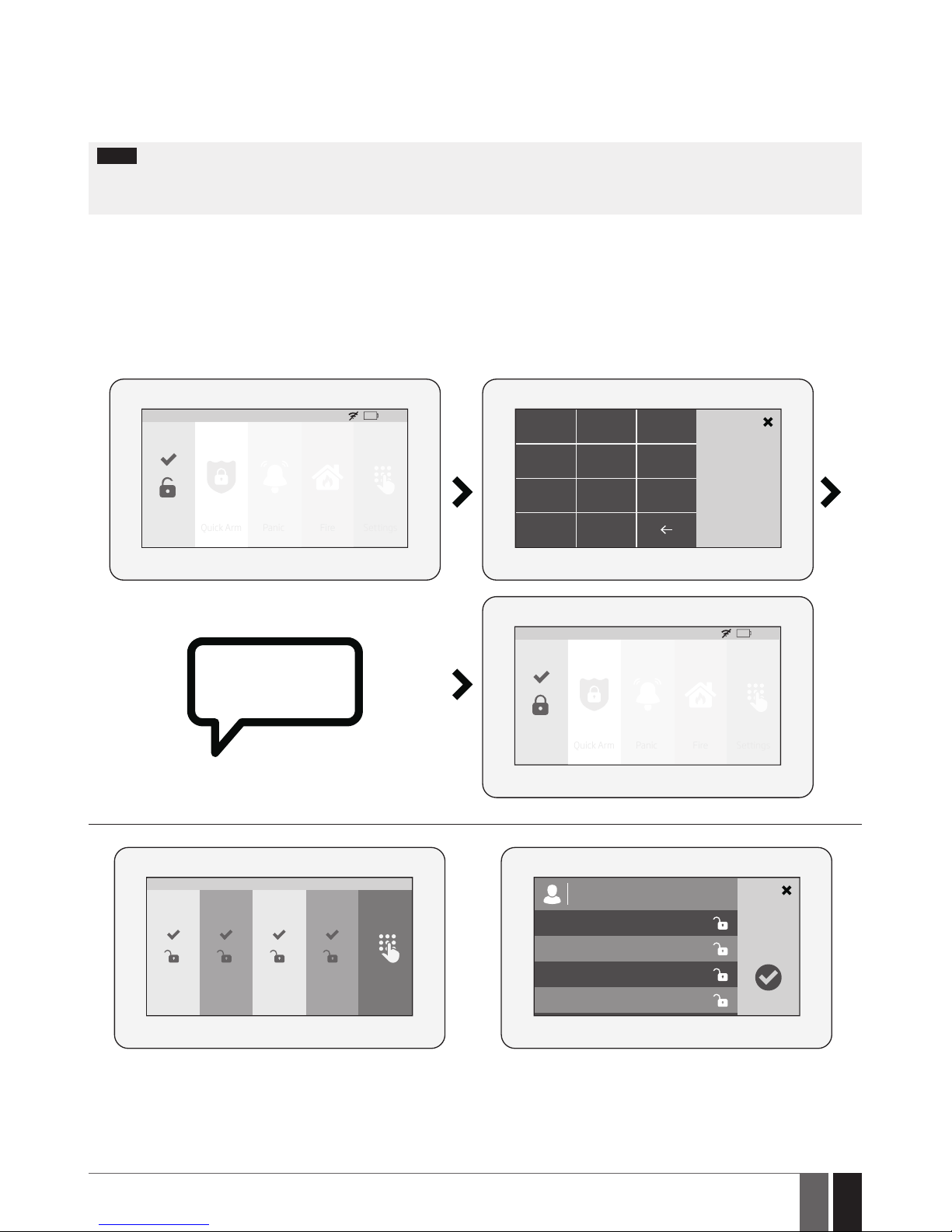
91
91
EN
ESIM384 Installation and Conguration Manual v1.1
board (top bar) are customizable, thus enabling the user to arrange the components in any way he/she wants.
To navigate through the menu, touch the desired main menu button representing a certain action or menu section. To enter a required
value, use the on-screen keyboard automatically appearing when necessary. Typically, the conguration of the system by EWKB5 touchpad
is carried out by accessing the Settings menu secured with the master code.
19.10.3. How to arm the system by EWKB5
NOTE: If the user fails to enter a correct user/master code 10 times in a row, the system will block the EWKB5 touchpad. While the touchpad
is blocked, the system prevents from completing any action. The touchpad will unblock once the alarm system is restarted (user may restart
alarm system by turning both mains power and backup power supply OFF or by sending an appropriate SMS command ssss_restart , where
“ssss” stands for user’s 4-digit SMS password, while the underscore character ”_” represents one space character).
1. To arm the system, touch the Partition button and enter a valid 4-digit user/master code PIN using the on-screen numpad. Alternatively,
the user can touch and hold the Quick Arm button in order to arm the system without entering the user code (Quick Arm button will let user
to arm all Partitions shown to the current touchpad). However, both methods require the user/master code in order to disarm the system.
If more than 1 Partition is being used, then after entering a valid 4-digit user/master code PIN user will get access to the additional Partition
select menu to choose Partitions which he wants to Arm or Disarm. Note that the user must enable/assign the Partition by using Eldes
Conguration software rst.
2. The system will initiate the exit delay countdown (by default – 15 seconds) intended for user to leave the secured premises. The countdown initiation will be indicated by voice-guided instructions followed by short beeps emitted by the touchpad.
HOME: 27 oC
HOME Quick Arm Fire Settings
01:19
Panic
1 2 3
User PIN
4
5 6
7
8
C
0
9
ARMING
HOME: 27 oC
HOME Quick Arm Fire Settings
01:19
Panic
PART1
V0.0
Settings
01:19
PART2 PART3 PART4
Select partitions
PART1
PART2
PART3
PART4
Page 92
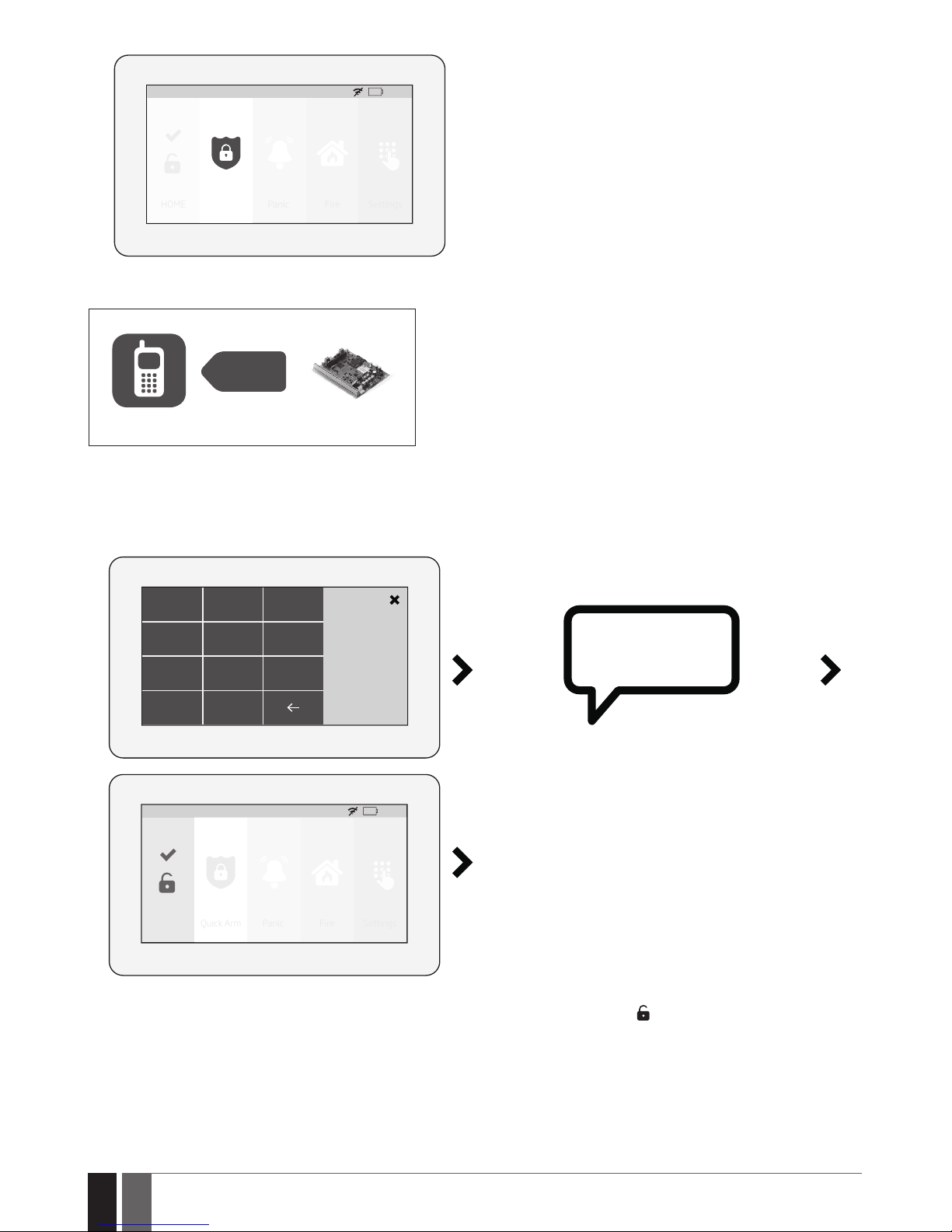
92
92
EN
ESIM384 Installation and Conguration Manual v1.1
HOME: 27 oC
HOME Quick Arm Fire Settings
01:19
Panic
3. Once the system is successfully armed, the touchpad will display icon on the Partition button followed by SMS text message conrmation
delivered to the listed user phone number (by default).
SMS
User
ESIM384
19.10.4. How to disarm and turn o alarm by EWKB5
1. The system will initiate the entry delay countdown (by default – 15 seconds) after the user has entered the secured premises. Entry delay
countdown is intended for user to enter a valid user code and disarm the system before the alarm is caused.
2. To disarm the system and/or turn o the alarm, enter a valid 4-digit user/master code using the on-screen numpad.
1 2 3
User PIN
4
5 6
7
8
C
0
9
SYSTEM IS
DISARMED
HOME: 27 oC
HOME Quick Arm Fire Settings
01:19
Panic
3. Once the system is successfully disarmed, the icon displayed on the Partition button will turn to followed by SMS text message conrmation delivered to the listed phone number (by default).
Page 93
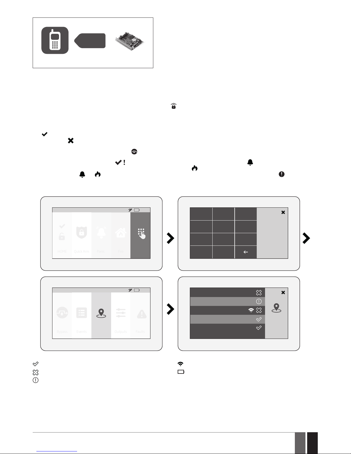
93
93
EN
ESIM384 Installation and Conguration Manual v1.1
SMS
User
ESIM384
19.10.5. About STAY mode and how to activate it by EWKB5
Stay mode allows the user to arm and disarm the alarm system without leaving the secured premises. Typically, this feature is used when
arming the system at home before going to bed.
The system can be Stay-armed using EWKB5 under the following condition:
Automatic – If a Delay-type zone with Stay attribute enabled exists and it is NOT violated during the exit delay countdown, the system will
arm in Stay mode. Once the system is successfully Stay-armed, the
icon will be indicated on the Partition button.
For more details on how to disarm and turn o the alarm by EWKB5 touchpad, please refer to section How to disarm the system and turn
OFF alarm by EWKB5.
19.10.6. Alarm indications and how to view violated zones / tampers by EWKB5
The
icon displayed on the Partition button indicates that no violated zones and/or tampers are present, therefore the partition is ready
for arming. If the icon is displayed instead, the partition is not ready for arming, therefore the user must restore all violated zones before
arming the partition. Alternatively, the violated zones and violated tampers associated with the zone can be bypassed (if a zone with the
Force attribute is bypassed, the following icon will appear on the main screen ; see 19.10.7. How to bypass a violated zone and
activate a bypassed zone by EWKB5) or a Force attribute enabled for a certain zone, resulting in partial arm (if a zone with the Force
attribute is violated, the following icon
will appear on the main screen; see Zone attributes). The icon displayed on the Partition
button represents all types of alarm, except tamper and re alarm, while the
icon represents re alarm exclusively. Note that when the
system is armed, both
and icons will disappear. In case of system fault presence, including tamper violation, the icon will appear
on the Partition button (see section 19.10.11. Fault messages).
To view the list of violated zones and/or violated tampers associated with certain zones, please open Zones section by navigating through
the menu as follows. Please, note that Master code is required for this action.
HOME: 27 oC
HOME Quick Arm Fire Settings
01:19
Panic
1 2 3
Master PIN
4
5 6
7
8
C
0
9
Alarm Zone1
Alarm Zone2
Zones
HOME: 27 oC
Bypass Events Outputs Faults
01:19
Zones
Alarm Zone4
EKB5W Police zone
EKB5W Fire zone
The following Zones section icons represent the state of a certain zone/tamper:
– zone/tamper is OK – not violated.
– zone is violated.
– tamper associated with a corresponding zone is violated.
– zone of wireless category.
- LOW battery of the corresponding zones sensor
19.10.7. How to bypass a violated zone and activate a bypassed zone by EWKB5
Arming the system is disabled while there’s at least 1 violated zone. Bypassing the zone allows to temporally disable a particular violated
zone and arm the alarm system afterwards.
In case the user attempts to arm the system, while a violated zone/tamper exists, the touchpad will automatically re-direct the user to the
Bypass section, which lists the violated zones/tampers, and deny system arming unless the violated zone/tamper is bypassed. Alternatively, the user can navigate through the menu as indicated below.
Page 94
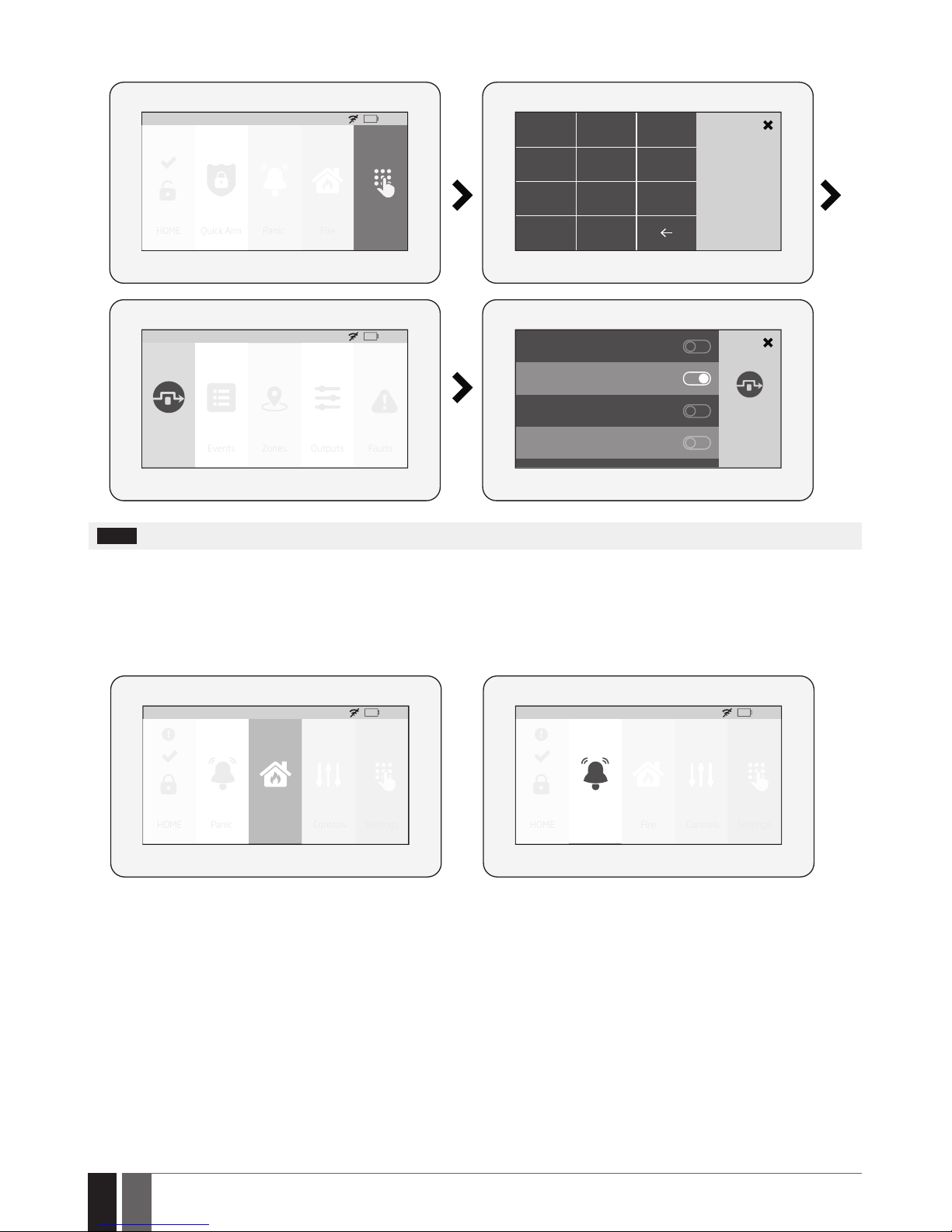
94
94
EN
ESIM384 Installation and Conguration Manual v1.1
1. To bypass a certain zone and the tamper associated with the zone, please slide the appropriate switch to the right.
2. To activate a bypassed zone, navigate through the aforementioned menu path and slide the bypassed zone’s switch to the left.
HOME: 27 oC
HOME Quick Arm Fire Settings
01:19
Panic
1 2 3
Master PIN
4
5 6
7
8
C
0
9
Alarm Zone1
HOME
Alarm Zone2
HOME
HOME: 27 oC
Bypass Events Outputs Faults
01:19
Zones
Alarm Zone4
HOME
EKB5W Police zone
HOME
NOTE: Zones can only be bypassed when the system is not armed.
The Conguration mode must be deactivated, while bypassing and activating a bypassed zone.
19.10.8. How to manually trigger panic or re alarm by EWKB5
In the event of emergency, the user might be able to manually trigger the re and panic alarm using EWKB5. By default the Fire and Panic
buttons are disabled, therefore they must be enabled under the Settings section beforehand.
To trigger re or panic alarm, please touch and hold the Fire or Panic button respectively. This action will be followed by a voice message
“Fire signal has been sent” and “Alarm signal has been sent” respectively. Also, panic or re button trigger silent or re virtual zone. No user/
master code is required for this action.
HOME: 27 oC
HOME Panic Fire Controls Settings
01:19
!
HOME: 27 oC
HOME Panic Fire Controls Settings
01:19
!
19.10.9. How to control PGM outputs by EWKB5
Using EWKB5 , user can remotely control the electric appliances linked to the PGM outputs of the associated wireless devices. The available
PGM outputs are listed under the Controls button menu. By default the Controls button is disabled, therefore it must be enabled under the
Advanced section beforehand. Alternatively, the user can enable an individual button for each available PGM output in order to control it
directly from the main menu. The button title reects the PGM output name that can be changed using ELDES Conguration software.
A. To turn a PGM output ON, touch the Controls button (path: Master menu -> Advanced ->Quick menu) in order to access the list of available PGM outputs and slide the switch of a certain PGM output to the right. Sliding the switch to the left will turn OFF the PGM output. No
code is required for these actions.
Page 95
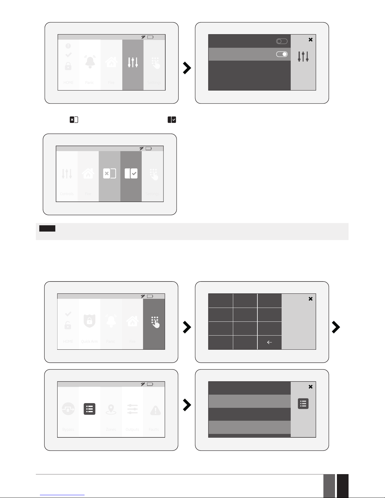
95
95
EN
ESIM384 Installation and Conguration Manual v1.1
HOME: 27 oC
HOME Panic Fire Controls Settings
01:19
!
Control1
Control2
B. To turn a PGM output ON by a single touch, please touch the corresponding PGM output button. Notice the icon displayed on the button
changing from
(represents PGM output’s OFF state) to (represents PGM output’s ON state). Touching the button again will turn OFF
the PGM output. No code is required for these actions. The maximum number of PGM outputs that can be shown on the Main menu is 5.
Controls
HOME: 27 oC
Fire Settings
01:19
Control1 Control2
NOTE: If you do not wish to display either the Controls button or individual PGM output button in the main menu due to the security reasons,
you can alternatively access the Controls menu under the Settings menu secured with Master PIN code.
19.10.10. How to view event log using EWKB5
The event log feature allows the system to chronologically register the records regarding certain system events, such as alarms, arm/
disarm events etc. Using EWKB5 the user can view the complete event log.
To view the event log, please navigate through the menu as follows. Please, note that this action requires Master PIN code.
HOME: 27 oC
HOME Quick Arm Fire Settings
01:19
Panic
1 2 3
Master PIN
4
5 6
7
8
C
0
9
Events from 1 - 16
Disarmed over KEYBOARD: HOME
User1
2016.09.06 10:40
HOME: 27 oC
Bypass Events Outputs Faults
01:19
Zones
Zone Alarm: HOME, Alarm Zone1
2016.09.06 10:39
Stay Armed over KEYBOARD: HOME
User1
2016.09.06 09:47
For more details on event log feature, please refer to section 28.1. Event Log
Page 96
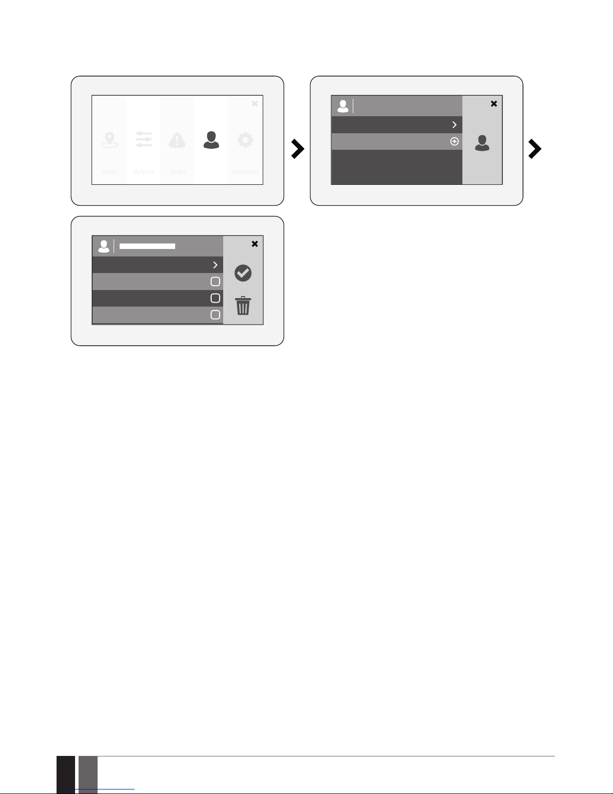
96
96
EN
ESIM384 Installation and Conguration Manual v1.1
19.10.11. User’s menu
Using EWKB5 , it is possible to add new users and congure which partitions the newly added user can control. The option to add a new
user is listed under the Users button menu. To add a new user, please navigate through the menu as follows. Please, note that this action
requires Master PIN code (only for the entrance to Settings menu).
User congurtion
Master
ADD NEW USER
PIN: Pin must be 4 digits
Home
Garage
Basment
Outputs Faults Users AdvancedZones
Page 97
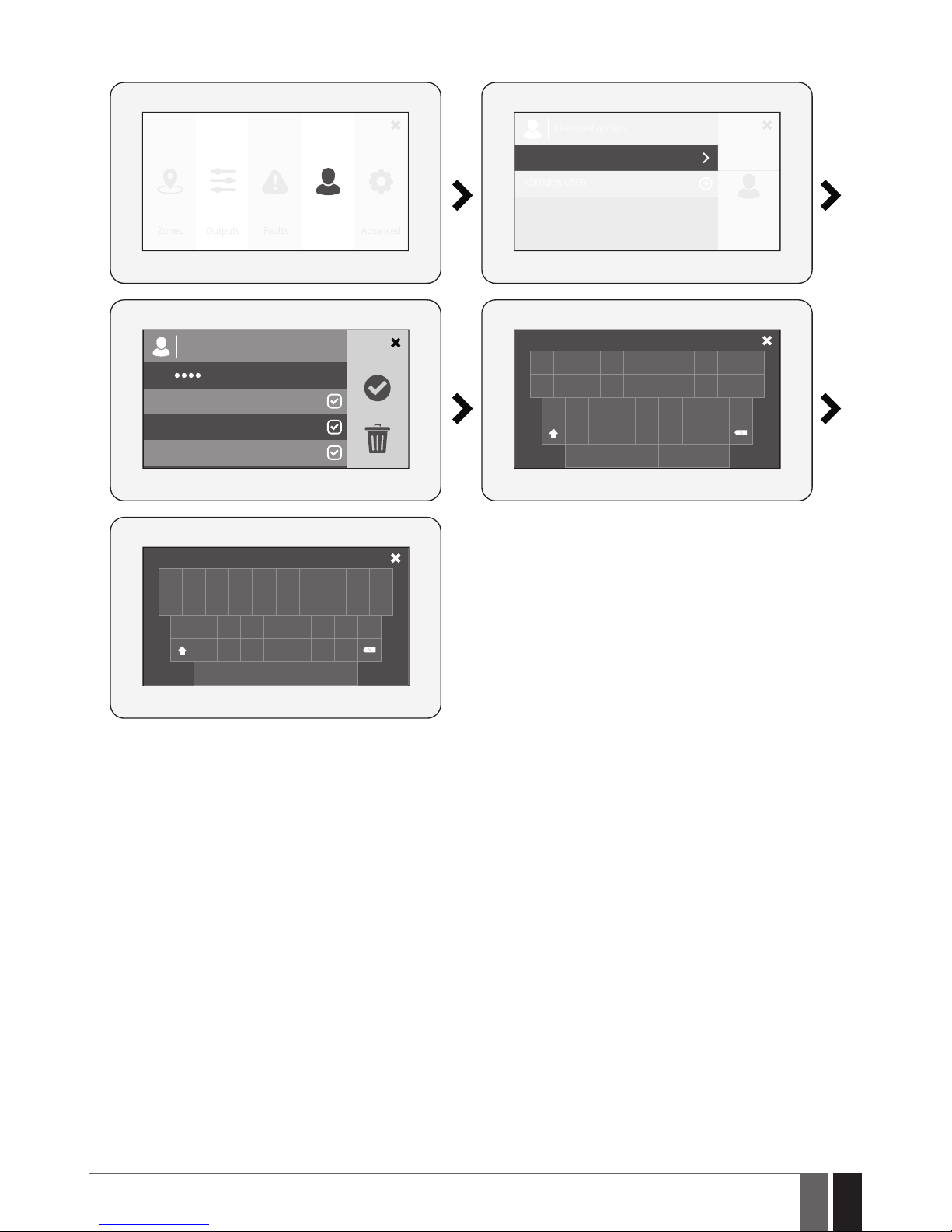
97
97
EN
ESIM384 Installation and Conguration Manual v1.1
19.10.12. Master’s menu
Using EWKB5 , it is possible to: edit Master settings, change Master name and Master PIN code; manage Partitions; delete selected users.
User congurtion
Master
ADD NEW USER
Master|
PIN:
Home
Garage
Basment
Master|
Outputs Faults Users AdvancedZones
1 2 3 4 5 6 7 8 9 0
Q W E R T Y U I O P
A S D F G H J K L
Z X C V B N M
space enter
1111|
1 2 3 4 5 6 7 8 9 0
Q W E R T Y U I O P
A S D F G H J K L
Z X C V B N M
space enter
Page 98
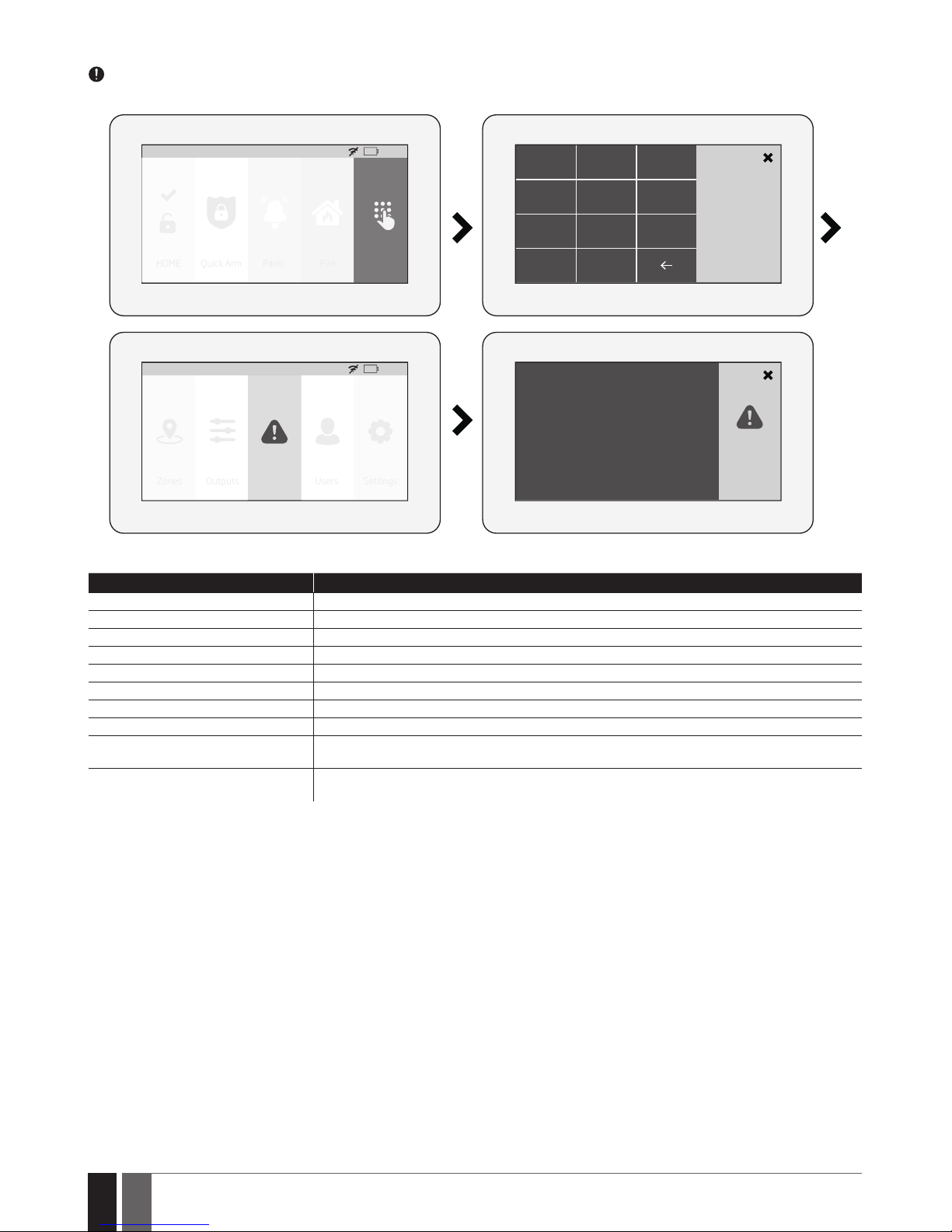
98
98
EN
ESIM384 Installation and Conguration Manual v1.1
19.10.13. Fault messages
icon displayed on the Partition button indicates the presence of certain system faults. To view a detailed list of the currently present
system faults, please navigate through the menu as follows. Please, note that Master PIN code is required for this action.
HOME: 27 oC
HOME Quick Arm Fire Settings
01:19
Panic
1 2 3
Master PIN
4
5 6
7
8
C
0
9
Tamper Violated
HOME: 27 oC
Outputs Faults Users Settings
01:19
Zones
A more detailed description of each system fault is provided in the table below.
Message Description
MAIN POWER LOST Mains power is lost
LOW BATTERY Low backup battery power - backup battery voltage is lower than required
BAD BATTERY Backup battery requires replacement - backup battery resistance is 2,5 or higher
RF JAMMER DETECTED Wireless signal is blocked by jammer
TAMPER VIOLATED One or more tampers are violated
DATE/TIME NOT SET Date/time not set
GSM FAILURE GSM connection is lost
WIRELESS COMMUNICATION FAILURE Wireless connection with a certain (all) wireless device is lost for 20 minutes or longer
EWM1 FAULT One or more EWM1 device faults exist - enter this menu item to view the existing EWM1 device
faults.
COMMUNICATION TO MS FAILED In case the system ends up with all unsuccessful attempts by all connections to deliver data mes-
sage to the monitoring station.
In order to nd out which particular tamper is violated, please open the Master-code-secured Zones section by navigating through the
menu as follows.
19.10.14. Advanced
The availability of additional conguration on EWKB5 touchpad screen depends on user’s selection. Once the user wakes the touchpad up,
enters to the Main menu’s Settings section and slides his nger across the LCD display, there he’ll see the button “Advanced”. When the user
click on that button, the additional menu will open up and from there on the user will be able to check or congure the following:
Temperature - indicates the current temperature of the secured area premises, monitored by the alarm system’s temperature sensor.
Sound settings - allows to change various sound settings of the EWKB5 (to increase/decrease speech or sound volume, to enable speech
in case of re alarm, etc. )
LCD settings - allows to change EWKB5 screen’s wake up time and brightness settings.
Quick menu - allows to select those necessary options (menu buttons), which will be shown on the main screen of EWKB5. Arrows (directed
up and down) oers to re-order the current layout of menu buttons.
Service Mode - this mode should be used when it is necessary to re-install some of the peripheral devices (to change batteries, open/close
enclosure and etc.) or make other installation changes. In this mode, system does not check for tamper faults so it won’t start siren alarm.
About - section of additional information about the touchpad model, alarm system model, hardware and rmware.
Page 99
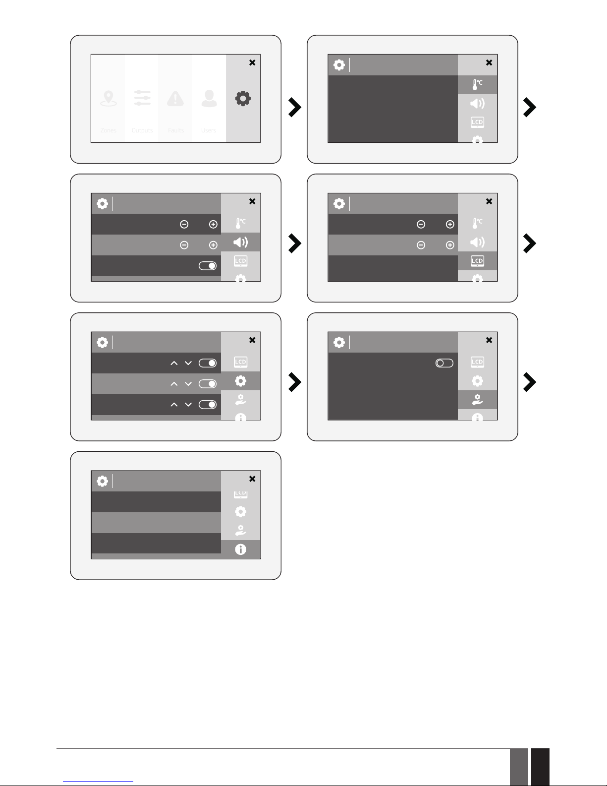
99
99
EN
ESIM384 Installation and Conguration Manual v1.1
Outputs Faults Users AdvancedZones
Temperature
Sound Settings
Speech volume
Sound volume 30 %
Speech on re
30 %
Quick Menu
Quick arm
Panic
Fire
About
Model:
EWKB5
Connected to:
ESIM384, FW: V1.0.17
Firmware version: V0.0
Service mode
Service mode
LCD Stteings
Brightness
Wake up time 10 s
75 %
Page 100
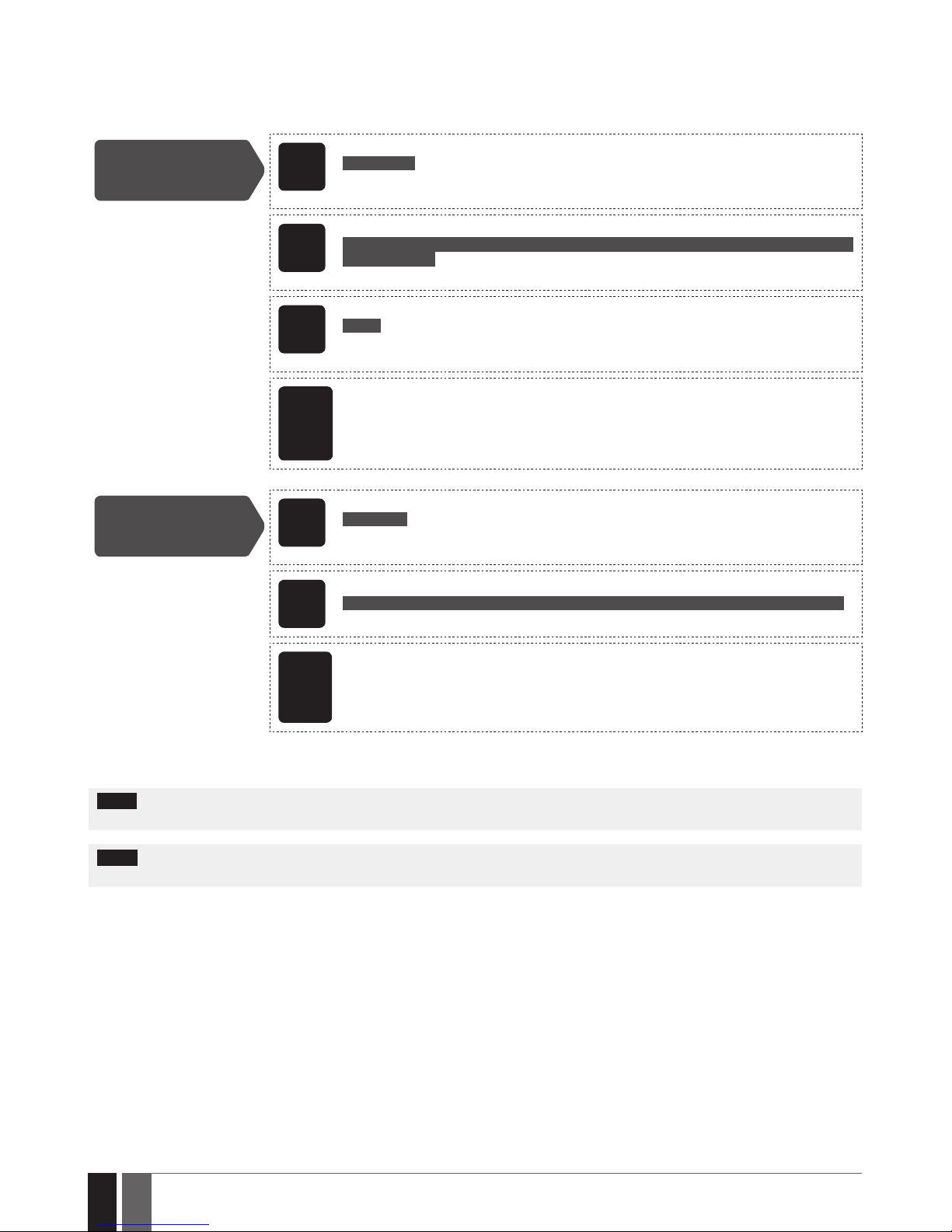
100
100
EN
ESIM384 Installation and Conguration Manual v1.1
20. WIRED SIREN/BELL
When the system is in alarm state, the siren/bell will sound until the set time (by default – 1 minute) expires or until the system is disarmed.
To set the alarm duration, please refer to the following conguration methods.
Set alarm duration
SMS
SMS text message content:
ssss_SIREN:t
Value: ssss – 4-digit SMS password; t – alarm duration, range – [0... 5] minutes.
Example: 1111_SIREN:4
EKB2
Menu path:
OK → iiii → OK → PRIMARY SETT INGS → OK → SIREN SETTINGS → OK → ALARM DURATION
→ OK → tt → OK
Value: iiii – 4-digit installer code; tt – alarm duration, range – [1... 10] minutes.
EKB3/
EKB3W/
EWKB4
Enter parameter 10 and alarm duration:
10 tt #
Value: tt – alarm duration, range – [00... 10] minutes.
Example: 1007#
ELDES
Conguration
soft-
ware
This operation may be carried out from the PC using the ELDES Conguration software.
View alarm duration
SMS
SMS text message content:
ssss_SIREN
Value: ssss – 4-digit SMS password
Example: 1111_SIREN
EKB2
Menu path:
OK → iiii → OK → PRIMARY SETT INGS → OK → SIREN SETTINGS → OK → ALARM DURATION
Value: iiii – 4-digit installer code.
ELDES
Cong-
uration
software
This operation may be carried out from the PC using the ELDES Conguration software.
For siren/bell wiring diagram, please refer to 2.3.3. Siren.
NOTE: The maximum supported alarm duration is 30 minutes that can be set up using ELDES Conguration software only. “0” value disables
the siren/bell.
NOTE: Due to battery power saving reasons, the wireless siren will sound for up to 6 minutes max. regardless of the set up alarm duration
value when it is longer than 6 minutes
 Loading...