

Page 1
ELDES GATE
CONTROLLER
ESIM120/ESIM320/ESIM320US
Page 2
User Manual v1.1
Valid for ESIM120/ESIM320 v21.05.00 and up
SAFETY INSTRUCTIONS
Please read and follow these safety guidelines to safeguard yourself and others:
• Gate controller ESIM120/ESIM320 (later referred to as “the system” or “ the device”) contains a built-in radio transceiver operating in
850/900/1800/1900 MHz (ESIM120 2G); 850/900/1800/1900/2100 MHz (ESIM320 3G/2G EU); 850/1900 MHz (ESIM320US 3G USA)
bands respectively.
• DO NOT use the system where it can cause potential danger and interfere with other devices – such as medical devices.
• DO NOT use the system in hazardous environment.
• DO NOT expose the system to high humidity, chemical environment or mechanical impact.
• NEVER install or carry out maintenance during stormy weather.
• DO NOT attempt to repair the system yourself – any repairs must be carried out by fully qualied personnel only.
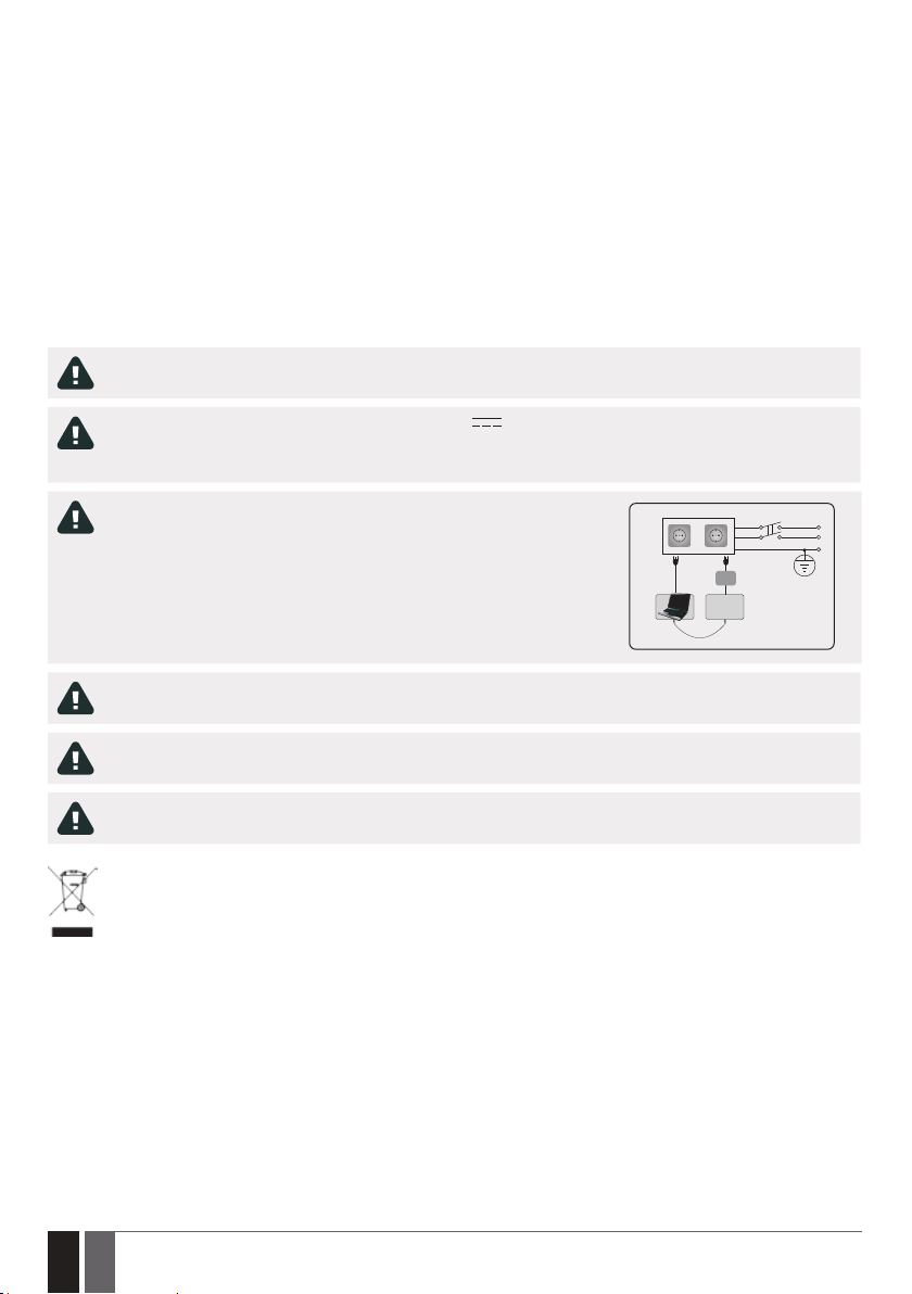
Disconnect the mains power before installing. Never install or carry out maintenance during stormy weather. The electric socket that powers the system must be easily accessible.
Please use the 10-24V 50Hz/60 Hz ~200mA AC or 10-24V 200mA DC power supply unit that meets the EN 609501 standard. Any additional device you connect to the system, such as a computer, must also be powered by an EN 60950-1
approved supply. When connecting the power supply to the system, switching the polarity terminal places does not have any
aect.
External power supply can be connected to AC mains only inside installation room
with automatic 2-pole circuit breaker capable of disconnecting circuit in the event of
short circuit or over-current condition. Open circuit breaker must have a gap between
connections of more than 3mm (0.12in) and the disconnection current 5A.
AC/DC
ESIM120/
ESIM320
USB cable
To switch the system o, unplug the external electric power supply from or any other linked device that the system is powered
from.
A blown fuse cannot be replaced by the user. The replacement fuse has to be of the kind indicated by the manufacturer (fuse
F1 model – MINISMDC050F 0.5A).
AC 230V
50 Hz/60 Hz/DC 24V
Phase
Null
PE
If you use a computer for the device conguration, it must be earthed.
The WEEE (Waste Electrical and Electronic Equipment) marking on this product (see left) or its documentation indicates that
the product must not be disposed of together with household waste. To prevent possible harm to human health and/or the environment, the product must be disposed of in an approved and environmentally safe recycling process. For further information
on how to dispose of this product correctly, contact the system supplier, or the local authority responsible for waste disposal
in your area.
2
2 EN
ELDES GATE CONTROLLER ESIM120/320 User Manual v.1.1
Page 3

CONTENTS
1. GENERAL INFORMATION ...........................................................................................................................................................5
2. TECHNICAL SPECIFICATIONS ....................................................................................................................................................5
2.1. Electrical and Mechanical Characteristics .....................................................................................................................................................5
2.2. Main Unit, LED Indicator and Connector Functionality ...............................................................................................................................6
2.3. Wiring Diagrams ................................................................................................................................................................................................7
3. INSTALLATION ...........................................................................................................................................................................8
4. GENERAL OPERATIONAL DESCRIPTION....................................................................................................................................9
5. CONFIGURATION METHODS ......................................................................................................................................................9
5.1. SMS Text Messages ...........................................................................................................................................................................................9
5.2. ELDES Conguration Tool Software ...............................................................................................................................................................9
5.2.1. Remote Connection ..........................................................................................................................................................................................9
5.2.2. Ending the Remote Connection Session .......................................................................................................................................................9
6. SYSTEM LANGUAGE .................................................................................................................................................................10
7. SMS PASSWORD .......................................................................................................................................................................10
8. ADMINISTRATOR PHONE NUMBERS .......................................................................................................................................11
9. DATE AND TIME........................................................................................................................................................................12
9.1. Automatic Date and Time Synchronization ................................................................................................................................................12
10. USER PHONE NUMBER DATABASE .........................................................................................................................................13
10.1. User Validity and Access Restriction ...........................................................................................................................................................15
11. OUTPUTS ................................................................................................................................................................................17
11.1. Output Names ..................................................................................................................................................................................................17
11.2. Output Control by Free of Charge Phone Call .............................................................................................................................................17
11.3. Output Control by SMS Text Message ..........................................................................................................................................................18
11.4. Output Control Conrmation by Call Back .................................................................................................................................................. 20
11.5. Output Control from any Phone Number....................................................................................................................................................20
11.6. Automatic Output Control ..............................................................................................................................................................................21
12. SCHEDULERS ..........................................................................................................................................................................22
13. EVENT LOG ............................................................................................................................................................................. 24
14. INPUTS ....................................................................................................................................................................................25
14.1. Input Names and Alarm Notications ..........................................................................................................................................................25
14.2. Disabling and Enabling Inputs ...................................................................................................................................................................... 26
15. SYSTEM INFORMATION. INFO SMS .........................................................................................................................................27
15.1. Periodic Info SMS .............................................................................................................................................................................................27
16. SYSTEM NOTIFICATIONS ....................................................................................................................................................... 28
16.1. SMS Text Message Delivery Restrictions ................................................................................................................................................... 28
16.2. SMSC (Short Message Service Center) Phone Number ............................................................................................................................ 28
17. GPRS NETWORK SETTINGS ................................................................................................................................................... 29
18. INCOMING PHONE NUMBER VERIFICATION SETTINGS ........................................................................................................ 30
19. REMOTE SYSTEM RESTART ................................................................................................................................................... 30
20. TECHNICAL SUPPORT ............................................................................................................................................................31
20.1. Troubleshooting ..............................................................................................................................................................................................31
20.2. Restoring Default Parameters ......................................................................................................................................................................31
20.3. Updating the Firmware via USB Cable .........................................................................................................................................................31
21. ELDES CLOUD SERVICES .........................................................................................................................................................32
22. RELATED PRODUCTS ..............................................................................................................................................................33
ELDES GATE CONTROLLER ESIM120/320 User Manual v.1.1
3
3EN
Page 4

TERMS OF USE
The following terms and conditions govern use of the ELDES GATE CONTROLLER device and contains important information on limitations
regarding the product’s use and function, as well as information on the limitations of the manufacturer’s liability. Please carefully read
these terms and conditions. For more information on your product, please visit eldesalarms.com
TECHNICAL SUPPORT
In order to ensure continuous and proper operation of the ELDES Gate Controller device and uninterrupted service, it is the responsibility
of the User to make sure that: (I) the product is properly installed, and (II) there is constant electrical supply. If you experience diculty
during the installation or subsequent use of the system, you may contact “ELDES, UAB” distributor or dealer in your country/region. For
more information, visit eldesalarms.com
WARRANTY PROCEDURES
Warranty and out of warranty service should be obtained by contacting the system integrator/dealer/retailer/e-tailer or distributor where
the customer purchased the product. When requesting for service, the proof of purchase and the product serial number must be provided.
The return of the defective product should be strictly through the original route of purchase, and the customers shall pack the product
appropriately to prevent the returned product from suering in the transportation.
MANUFACTURER WARRANTY
“ELDES, UAB” provides a limited warranty for its products only to the person or entity that originally purchased the product from “ELDES,
UAB” or its authorized distributor or retailer and materials under normal use of the system for a period of twenty four (24) months from the
date of shipment by the “ELDES, UAB” (Warranty Period). Warranty obligations do not cover expandable materials (power elements and/or
batteries), holders and enclosures. The warranty remains valid only if the system is used as intended, following all guidelines outlined in
this manual and in accordance with the operating conditions specied. The warranty is void if the system has been exposed to mechanical
impact, chemicals, high humidity, uids, corrosive and hazardous environments or force majeure factors. If a hardware defect arises and a
valid claim is received within the Warranty Period, at its own discretion, “ELDES, UAB” will either (a) repair a hardware defect at no charge,
using new or refurbished replacement parts, or (b) exchange the product with a product that is new or which has been manufactured from
new or serviceable used parts and is at least functionally equivalent to the original product, or (c) refund the purchase price of the product.
LIMITED LIABILITY
The buyer must agree that the system will reduce the risk theft, burglary or other dangers but does not provide guarantee against such
events. “ELDES, UAB” will not assume any responsibility regarding personal or property, or revenue loss while using the system. “ELDES,
UAB” shall also assume no liability due to direct or indirect damage or loss, as well as unreceived income when using the system, including
cases, when the damages arise due to the above mentioned risks, when due to breakdown or malfunction the user is not informed in a
timely manner about a risk which has arisen. In any case, the liability of “ELDES, UAB”, as much as it is allowed by the laws in force, shall not
exceed the price of acquisition of the product.
CONSUMER PROTECTION LAWS
FOR CONSUMERS WHO ARE COVERED BY CONSUMER PROTECTION LAWS OR REGULATIONS IN THEIR COUNTRY OF PURCHASE OR, IF
DIFFERENT, THEIR COUNTRY OF RESIDENCE, THE BENEFITS CONFERRED BY THIS WARRANTY ARE IN ADDITION TO ALL RIGHTS
AND REMEDIES CONVEYED BY SUCH CONSUMER PROTECTION LAWS AND REGULATIONS. This warranty grants upon you specic
legal rights, and you may also have other rights that vary by country, state or province.
Dear Customer,
Thank you for choosing to purchase ELDES GATE CONTROLLER ESIM120/ESIM320. Your thoughtful decision will ensure reliable solution
for many years as all ELDES products are manufactured to meet the highest standards.
We are condent that you will be completely satised with your product. However, in the unlikely event that you do experience a
problem, please contact the dealer from whom you made your purchase.
ELDES, UAB
eldesalarms.com
Contents of Pack
Item Quantity
1. ESIM120/ESIM320 .................................1
2. User manual ............................................1
3. Antenna ...................................................1
Not included:
• SIM card – we recommend you get a contract SIM, not Pay As You Go.
• mini-USB cable – can be obtained from your local distributor.
Copyright © “ELDES, UAB”, 2018. All rights reserved.
It is strictly forbidden to copy and distribute the information contained in this document or to pass thereof to
a third party without an a priori written authorization obtained from “ELDES, UAB”. “ELDES, UAB” reserves the
right to update or modify this document and/or related products without an a priori warning. “ELDES, UAB”
hereby declares that ELDES gate controller is in compliance with the essential requirements and other relevant provisions of Directive 1999/5/EC. The declaration of conformity may be consulted at eldesalarms.com.
4
4 EN
ELDES GATE CONTROLLER ESIM120/320 User Manual v.1.1
Page 5

1. GENERAL INFORMATION
ELDES GATE CONTROLLER ESIM120/ESIM320 is a micro-controller based device intended to provide access control for gate automatics,
road barriers or to remotely turn ON/OFF any electrical appliance via the GSM/3G network.
Examples of using the system:
• Access control.
• Parking lot control of residential houses or oces.
• Gate control of private houses.
• Any electrical appliance control: lighting, watering, heating etc.
• Remote reboot of the “frozen” systems, such as computer network or a server.
Main features
• Manual output control by free of charge phone call.
• Automatic output control in accordance with the scheduled time.
• Congurable output pulse duration.
• Automatic date and time synchronization.
• Up to 5 administrators for system conguration by SMS text messages, acceptance of input alarm SMS text messages, output control
by SMS text message and free of charge phone call.
• User database capacity – up to 2000 users for output control by free of charge phone call.
• User phone number validity limitation in accordance with a set deadline (date/time) or number of rings to the system.
• Output control restriction for users in accordance with the specied weekdays and time.
• Event log of 1000 events containing date and time as well as administrator/user phone number and user name who controlled the
output.
• 3 inputs with customizable alarm texts for notication on gate state or in case it gets jammed.
• Periodic self-test notication by SMS text message to administrator phone number.
2. TECHNICAL SPECIFICATIONS
2.1. Electrical and Mechanical Characteristics
Supply voltage ...............................................................10-24V 50Hz/60Hz ~ 200mA max / 10-24V 200mA max
Current used in idle state .............................................up to 50mA
Modem frequency .........................................................ESIM120 2G - 850/900/1800/1900MHz; ESIM320 3G/2G EU - 900/1800/2100MHz;
ESIM320US 3G USA - 850/1900MHz
Number of outputs .......................................................2
Output type....................................................................Relay; NO (normally-open) or NC (normally-closed) - congurable
Maximum commuting output values .........................24V 50Hz/60Hz ~ 0,5A / 24V 1A
Number of low-level (negative) inputs .....................2
Number of high-level (positive) inputs .....................1
Low-level (negative) input value range ....................0... 16V -0.8... -0.4mA
High-level (positive) input value range.....................5... 50V 0.17 .... 1.7mA
Default inputs connection type .................................NO (normally-open)
Degree of protection ....................................................Complies with IP 20
Dimensions ....................................................................87x107x29mm (3.43x4.21x1.14in)
Operating temperature range ....................................-20…+55 °C (-4... +131°F )
Humidity .........................................................................0-90% RH @ 0... +40°C (0-90% RH @ +32... +104°F) (non-condensing)
ELDES GATE CONTROLLER ESIM120/320 User Manual v.1.1
5
5EN
Page 6
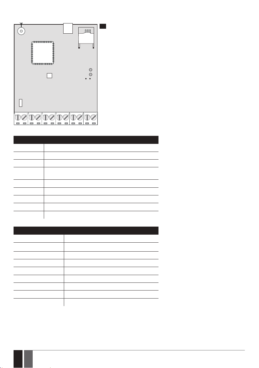
2.2. Main Unit, LED Indicator and Connector Functionality
USB
1
ANT
MO D E M
MIC
SIM CARD
SIM STAT
NETW
DEF
F1
AC/DC RELAY1RELAY2 COM Z5 Z4 Z3 Z2 Z1
Main Unit Functionality
ANT Antenna SMA type connector
USB Mini USB port
SIM CARD SIM card slot / holder
MODEM ESIM120 -850/900/1800/1900 MHz modem; ESIM320 -
MIC N/A
SIM STAT Red LED, indicating SIM card status
NETW Green LED, indicating signal strength
DEF Pins for restoring default settings
F1 0.5A fuse
850/900/1800/1900/2100 MHz modem
Connector Functionality
AC/DC Power supply terminals
RELAY1 Output C1 terminal
RELAY2 Output C2 terminal
COM Common terminal
Z5 N/A
Z4 N/A
Z3 Low-level (negative) input terminal
Z2 High-level (positive) input terminal
Z1 Low-level (negative) input terminal
6
6 EN
ELDES GATE CONTROLLER ESIM120/320 User Manual v.1.1
Page 7
LED Indicator Functionality
SIM STAT indication SIM card status
OFF No mains power / Successfully connected to GSM/3G network
Steady ON SIM card is attempting to connect to the GSM/3G network / SIM card is not present / PIN code
NETW indication Signal strength
OFF No GSM/3G signal
Flashing every 1 sec. Poor
Flashing several times per sec. Medium
Steady ON Excellent
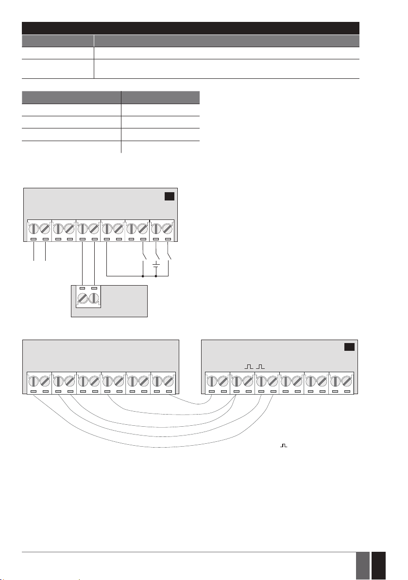
2.3. Wiring Diagrams
General wiring
ESIM120/ESIM320
enabled
2
AC/DC
Power
supply
Example of ESIM120/ESIM320 system wiring to gate automation device
RELAY2RELAY1 COM Z3 Z2 Z1
+
-
GATE
AUTOMATION
DEVICE
ESIM120/ESIM320 GATE AUTOMATION DEVICE
AC/DC RELAY1RELAY2 COM Z5 Z4 Z3 Z2 Z1 F0 +24vGND
FO Fault output; open
collector type
+24V Power supply
output for powering
aux. equipment
Pulse input
GND Common terminal
3
ELDES GATE CONTROLLER ESIM120/320 User Manual v.1.1
7
7EN
Page 8
3. INSTALLATION
• The system should be installed indoors, in stationary environment ONLY.
• For the connection of input/output terminals, use 0.50 mm2 (0.02in2) thread unshielded cable of up to 100m (328.08ft) length.
1. Wire up the system in accordance with the wiring diagrams (see 2.3 Wiring Diagrams for more details).
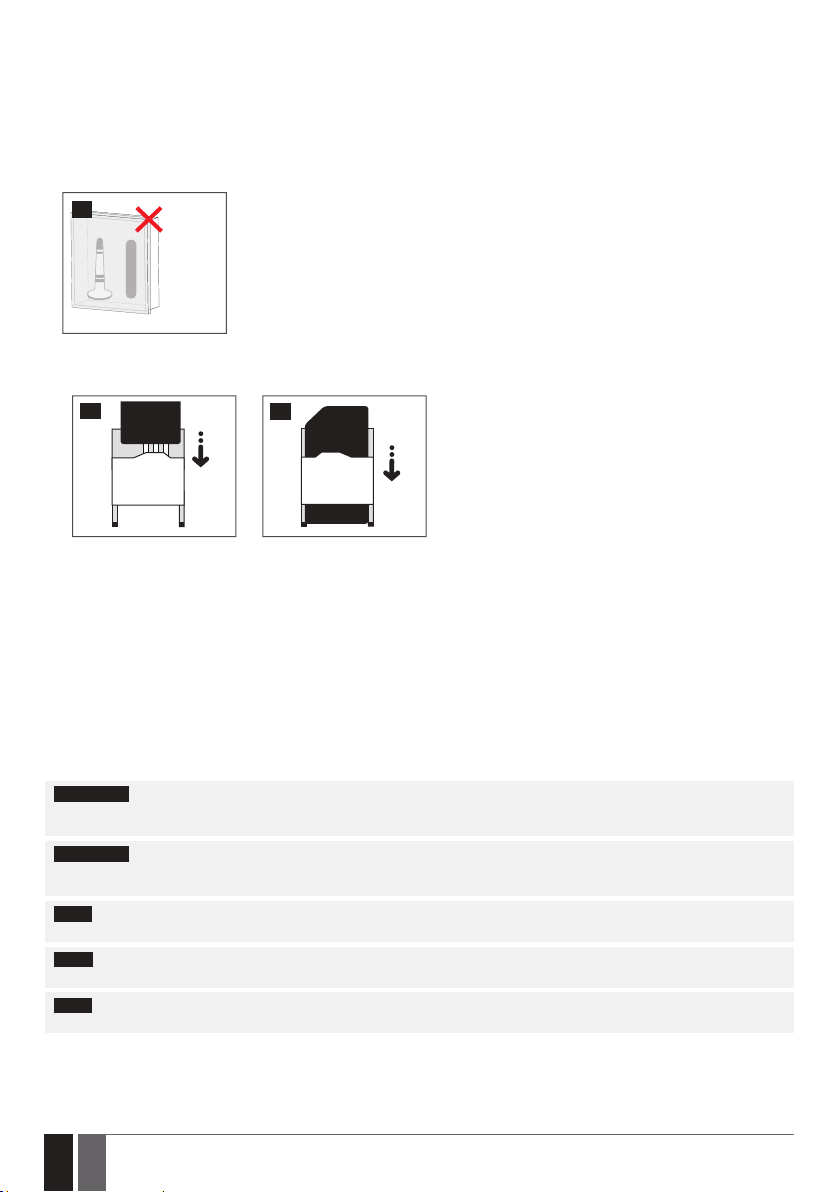
2. Connect the antenna. Based on the type of antenna supplied with ESIM120/ESIM320 unit, follow the recommendations for the antenna installation:
4
Antenna
Never install in the following
locations:
• inside the metal cabinet
• closer than 20cm (7.87in) from
the power lines
3. Disable the PIN code request of the SIM card by inserting it into a mobile phone and following the proper menu steps.
4. Once the PIN code is disabled, insert the SIM card into the SIM card slot / holder of ESIM120/ESIM320 system.
5
5. Power up the system and wait until indicator SIM STAT lights up indicating SIM card status.
6. Once the indicator SIM STAT lights OFF, the illuminated indicator NETW lights up indicating that the system has successfully connected
to GSM/3G network. To nd the strongest signal, position the antenna and follow the indications provided by NETW indicator (see 2.2.
Main Unit, LED Indicator and Connector Functionality for more details).
7. Change the system language if necessary (see 6. SYSTEM LANGUAGE for more details).
8. Change the default SMS password (see 7. SMS PASSWORD for more details).
9. Set the phone number for Admin 1 (see 8. ADMINISTRATOR PHONE NUMBERS for more details).
10. Set system date and time (see 9. DATE AND TIME for more details).
11. Once the system is fully congured, it is ready for use. However, if you fail to receive a reply by SMS text message from the system,
please check the SMSC (Short Message Service Center) phone number. For more details regarding the SMS center phone number,
please refer to 16.2. SMSC (Short Message Service Center) Phone Number.
ATTENTION: ESIM120 is NOT compatible with pure 3G SIM cards. Only 2G SIM cards and 3G SIM cards with 2G/GSM prole enabled are
supported. Meanwhile, ESIM320 is compatible with any SIM card and supports both 2G and 3G connections. For more details, please
contact your operator.
ATTENTION: We also recommend you to disable call forwarding, voice mail/text message reports on missed/busy calls and
similar services that might cause incorrect system operation. Please contact your operator for more details on these services and how
to disable them.
NOTE: For maximum system reliability we recommend you do NOT use a Pay As You Go SIM card. Otherwise, in the event of insucient
credit balance on the SIM card, the system would fail to make a phone call or send SMS text messages.
NOTE: We advise you to choose the same SIM provider for your system as for your mobile phone. This will ensure the fastest, most
reliable SMS text message delivery service and phone call connection.
NOTE: Even though the installation process of ESIM120/ESIM320 is not too complicated, we still recommend to perform it by a person
with basic knowledge in electrical engineering and electronics to avoid any system damage.
6
8
8 EN
ELDES GATE CONTROLLER ESIM120/320 User Manual v.1.1
Page 9
4. GENERAL OPERATIONAL DESCRIPTION
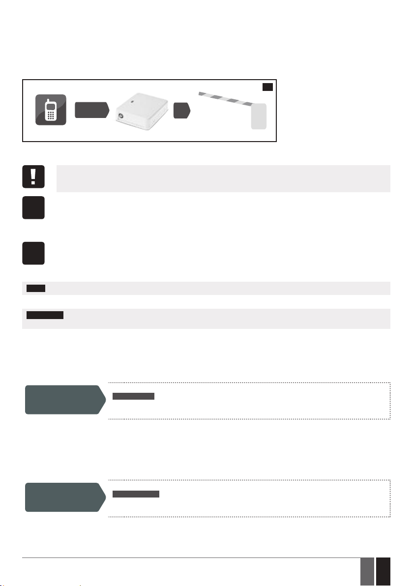
When a phone call is made to the phone number of the SIM card inserted in ESIM120/ESIM320, the system will verify if the caller’s phone
number exists in the device database. If the caller is one of the 5 administrators or the phone number belongs to one of the 2000 database
users, the system will reject the phone call, thus making the phone call free of charge, and open the gate. If the phone number is not recognized, the system will reject the phone call and ignore it. The gate controller can also control your gate automatically in accordance with the
scheduled time or by sending an SMS text message from the administrator’s phone number.
By connecting a sensor to one of the 3 inputs, the administrators can receive SMS text messages regarding the gates that failed to close
during the set time period.
7
CALL
User/Admin
ESIM120/ESIM320
5. CONFIGURATION METHODS
5.1. SMS Text Messages
In this document the underscore character ”_” represents one space character. Every underscore character must be replaced with a single space character. There must be no spaces or other unnecessary characters at the beginning and at the
end of the SMS text message.
In order to congure and control the system by SMS text message, send the text command to the ESIM120/ESIM320 system
phone number from one of the listed administrator phone numbers. The structure of SMS text message consists of 4-digit
SMS
SMS password (the default SMS password is 0000 – four zeros), the parameter and value. For some parameters the value
does not apply e. g. STATUS. The variables are indicated in lower-case letters, while a valid parameter value range is indicated
5.2. ELDES Conguration Tool Software
Cong
5.2.1. Remote Connection
ELDES Conguration Tool software provides remote system conguration ability via Internet using one of the following methods:
• ELDES proxy server (recommended). The connection can be established on the system via GPRS network.
• Running TCP/IP server on ELDES Conguration Tool (advanced). The connection can be established on the system via GPRS network.
In order to start using the remote conguration feature, please run the step-by-step wizard and follow the steps provided in the start page
of ELDES Conguration Tool software. Please, note that it will be necessary to send an SMS text message to the system’s phone number
in order to initiate the remote connection. By following the steps you will be instructed on what text must be sent to the system’s phone
number in such case (see the SMS command below).
5.2.2. Ending the Remote Connection Session
After the system conguration is complete, use one of the following methods to end the conguration process:
• Click Disconnect or Stop button and close ELDES Conguration Tool software;
• The session will automatically expire in 20 minutes. Before the last 5 minutes, the software will oer the user to extend the session
• Alternatively, the connection with the server can be terminated at any time by sending an SMS text message.
Once the session is expired or terminated, the system will reply with an SMS text message conrming the end of the session.
in brackets.
Software ELDES Conguration Tool is intended for the gate controller ESIM120/ESIM320 conguration locally via USB port or
remotely via GPRS network connection. This software simplies system conguration process by allowing to use a personal
Tool
computer in the process. Before starting to use ELDES Conguration Tool software, please read the user guide provided in the
software’s HELP section.
ELDES Conguration Tool is freeware and can be downloaded from eldesalarms.com
NOTE: ELDES Conguration Tool software is secured with SMS password. The default SMS password is 0000 (see 7. SMS PASSWORD).
ATTENTION: When remote connection session is initialized (i.e. when you send an SMS text command and receive the answer from the
system), then ELDES Cloud Services feature will NOT work and becomes inaccessible until the remote connection session is over.
SMS text message content:
Start the connection
for another 20 minutes.
Terminate the
connection
ssss_STCONFIG
Value: ssss – 4-digit SMS password.
Example: 1111_STCONFIG
SMS text message content:
ssss_ENDCONFIG
Value: ssss – 4-digit SMS password.
Example: 1111_ENDCONFIG
ELDES GATE CONTROLLER ESIM120/320 User Manual v.1.1
9
9EN
Page 10
6. SYSTEM LANGUAGE
The system comes equipped with a multiple languages for communication with the administrator by SMS text messages. The default system language depends on the rmware, which is based on the customer’s location.
List of currently available system languages:
• English
• Estonian
• German
• Lithuanian
• French
• Slovak
SMS text message content:
LN
Set system language
SMS
Value: LN – language index; range – [EN – English, EE – Estonian, DE – German, LT – Lithua-
nian, FR – French, SK – Slovak].
Example: LT
Cong
NOTE: To change the language once the system has already been congured, you need to reset the device to the default conguration. For
more details on how to do this, please refer to 20.2. Restoring Default Parameters.
This operation may be carried out from the PC using the ELDES Conguration Tool software.
Tool
7. SMS PASSWORD
For security reasons, the system uses the following type of password:
• SMS password – 4-digit password used for system conguration and control from administrator phone number by SMS text mes-
sages and logging in to ELDES Conguration Tool software . By default, SMS password is 0000, which MUST be changed (device
will not reply to any of SMS messages until SMS password is changed!)!
SMS text message content:
wwww_PSW_ssss
Set SMS password
NOTE: The system rejects the SMS text messages containing wrong SMS password even from a listed administrator phone number.
SMS
Cong
Tool
Value: wwww – 4-digit default SMS password; ssss – 4-digit new SMS password; range –
[0001... 9999].
Example: 0000_PSW_1111
This operation may be carried out from the PC using the ELDES Conguration Tool software.
10
10 EN
ELDES GATE CONTROLLER ESIM120/320 User Manual v.1.1
Page 11
8. ADMINISTRATOR PHONE NUMBERS
The system supports up to 5 administrator phone numbers identied as Admin 1 through 5. When the phone number is set, the administrator will be able to congure and control the system by SMS text messages as well as by free of charge phone call and receive the input alarm
SMS text messages from the system (see 14.1. Input Names and Alarm Notication). The system allows to assign output C1, output C2
or both outputs (simultaneous control) to a certain administrator.
By default, the system accepts incoming calls and SMS text messages from any phone number. Once the administrator phone number is
listed, the system will ignore any incoming calls and SMS text messages from a non-listed phone number as well as it will reject the SMS
text messages containing wrong SMS password even from a listed administrator phone number. For more details on how to enable output
control from a non-listed phone number, please refer to 11.5. Output Control from any Phone Number.
To set Admin 1 phone number is mandatory (using the device without entered administrator number is forbidden!), while the other 4 are
optional. The supported phone number format is the following:
• International (w/o plus) – The phone numbers must be entered starting with an international country code in the following format:
[international code][area code][local number], example for UK: 44170911XXXX1.
SMS text message content:
Set administrator
phone number
ssss_NRas:ttteeellnnuumm
SMS
Value: ssss – 4-digit SMS password; as – administrator phone number slot, range – [1... 5];
ttteeellnnuumm – up to 15 digits administrator phone number.
Example: 1111_NR1:44170911XXXX1
Cong
View administrator
phone numbers
Cong
Assign output
(-s) to individual
administrator
Delete administrator
phone number
ATTENTION: NEVER set a phone number of the device’s SIM card as an administrator phone number!
ATTENTION: Once Admin 1 phone number is set, the system will allow only to modify it.
ATTENTION: Multiple administrator phone numbers can be set by a single SMS text message, Example: 1111_NR1:44170911XXXX1_
NR5:44170911XXXX2_NR2:44170911XXXX3_NR3: 44170911XXXX4
NOTE: Multiple administrator phone numbers can be deleted by a single SMS text message, Example: 1111_NR2:DEL_NR4:DEL_
NR3:DEL
Cong
Cong
This operation may be carried out from the PC using the ELDES Conguration Tool software.
Tool
SMS text message content:
ssss_HELPNR
SMS
Value: ssss – 4-digit SMS password.
Example: 1111_HELPNR
This operation may be carried out from the PC using the ELDES Conguration Tool software.
Tool
This operation may be carried out from the PC using the ELDES Conguration Tool software.
Tool
SMS text message content:
ssss_NRas:DEL
SMS
Value: ssss – 4-digit SMS password; as – administrator phone number slot, range – [2... 5].
Example: 1111_NR2:DEL
This operation may be carried out from the PC using the ELDES Conguration Tool software.
Tool
NOTE: The administrator can control any output by SMS text message regardless of the output assigned to the administrator phone number
(see 11.3. Output Control by SMS Text Message).
NOTE: By default, the system is restricted to send out up to 25 SMS text messages daily and up to 400 SMS text messages monthly. For
more details on SMS text message delivery restriction management, please refer to 16.1. SMS Text Message Delivery Restrictions
For more details on output control, please refer to 11. OUTPUTS.
ELDES GATE CONTROLLER ESIM120/320 User Manual v.1.1
11
11EN
Page 12
9. DATE AND TIME
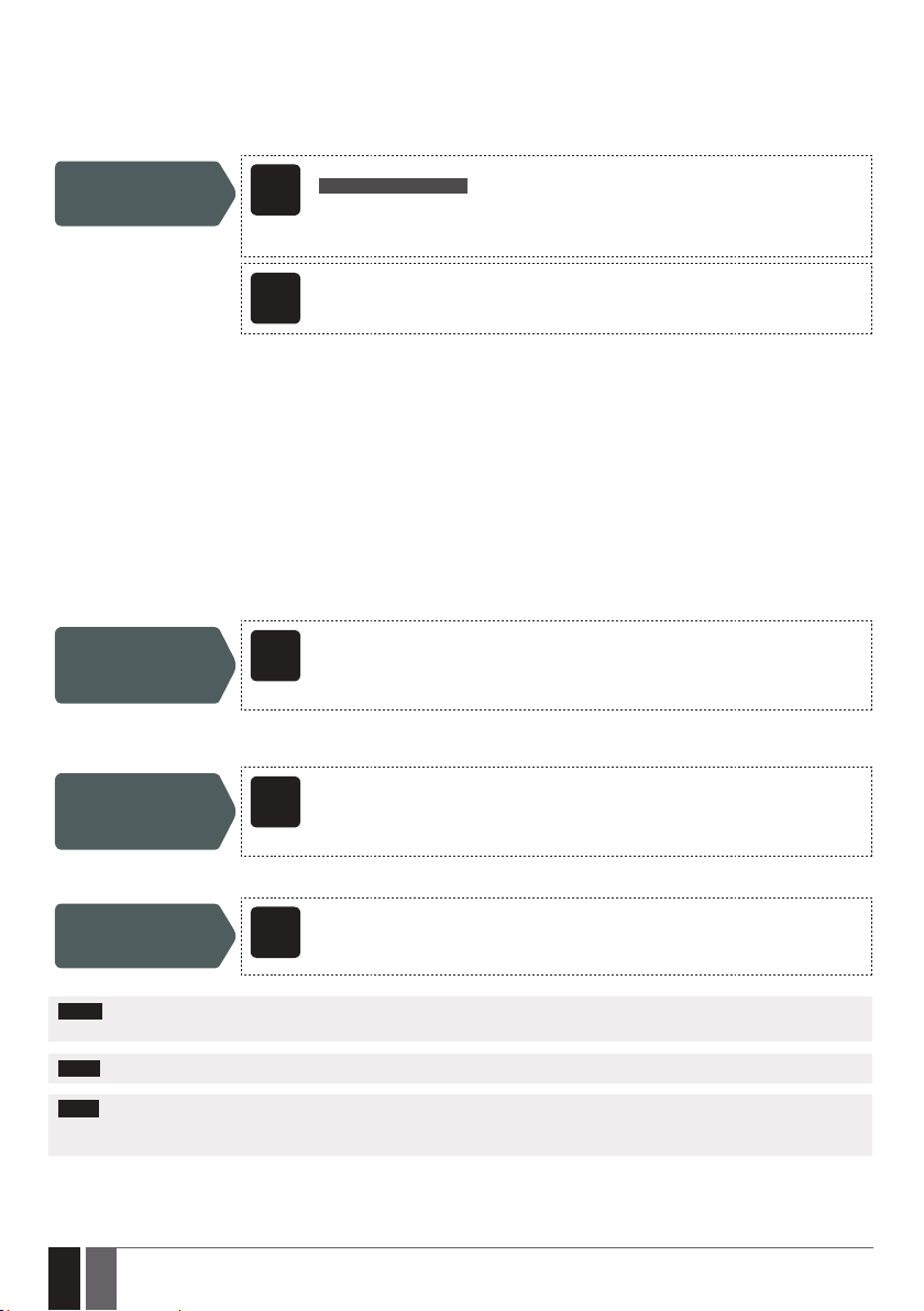
The system comes equipped with internal real-time clock (RTC) that keeps track of the current date and time. Once the system is up and
running, the user must set the correct date and time, otherwise the system will not operate properly. By default, after shutting down and
starting up the system, the date and time must be set again. In order to avoid manual date and time set up, please use the automatic date
and time synchronization feature (see 9.1. Automatic Date and Time Synchronization).
SMS text message content:
ssss_yyyy.mm.dd_hr:mn
Set date and time
SMS
Value: ssss – 4-digit SMS password; yyyy – year; mm – month, range – [01... 12]; dd – day,
range – [01... 31]; hr – hours, range – [00... 23]; mn – minutes, range – [00... 59].
Example: 1111_2013.03.16_14:33
Cong
9.1. Automatic Date and Time Synchronization
This feature enables the system to set the date and time automatically without the user being involved in this process. The system supports the following methods of automatic date and time synchronization that are used automatically on system start-up and periodically
(by default – every 30 days):
• Via GSM network – Once enabled, the system automatically sends a date/time request to the GSM operator. This method is the
most accurate synchronization method. Some GSM operators might not support it.
• By SMS text message – Once enabled, the system automatically sends the SMS text message to its own phone number and re-
trieves the date and time from the SMS text message reply, as the included date and time is set by the SMSC (SMS center). This
method is not as accurate as the synchronization via GSM network, but always eective.
By default, synchronization via GSM network is disabled. To enable/disable automatic date and time synchronization via GSM network,
please refer to the following conguration methods.
Enable/disable
synchronization via
GSM network
By default, synchronization by SMS text message is disabled. To enable/disable automatic date and time synchronization by SMS text
message, please enter/remove device phone number using one of the following conguration methods.
Enter/remove device
phone number for
synchronization by
SMS text message
By default, the date and time synchronization period is 30 days. To set a dierent period, please refer to the following conguration methods.
Set synchronization
period
Cong
Cong
Cong
This operation may be carried out from the PC using the ELDES Conguration Tool software.
Tool
Tool
This operation may be carried out from the PC using the ELDES Conguration Tool software.
Tool
This operation may be carried out from the PC using the ELDES Conguration Tool software.
This operation may be carried out from the PC using the ELDES Conguration Tool software.
Tool
NOTE: When setting up automatic date and time synchronization feature remotely, you may wish to restart the system when done.
For more details, please refer to 19. REMOTE SYSTEM RESTART.
NOTE: 0 value disables periodic synchronization.
NOTE: When both synchronization methods are enabled, the system will always attempt to synchronize date and time via GSM network
every time the system shuts down and starts up again and in accordance with the set period value. In the event of rst method’s failure,
the system will attempt to use the SMS text message method as a backup.
12
12 EN
ELDES GATE CONTROLLER ESIM120/320 User Manual v.1.1
Page 13
10. USER PHONE NUMBER DATABASE
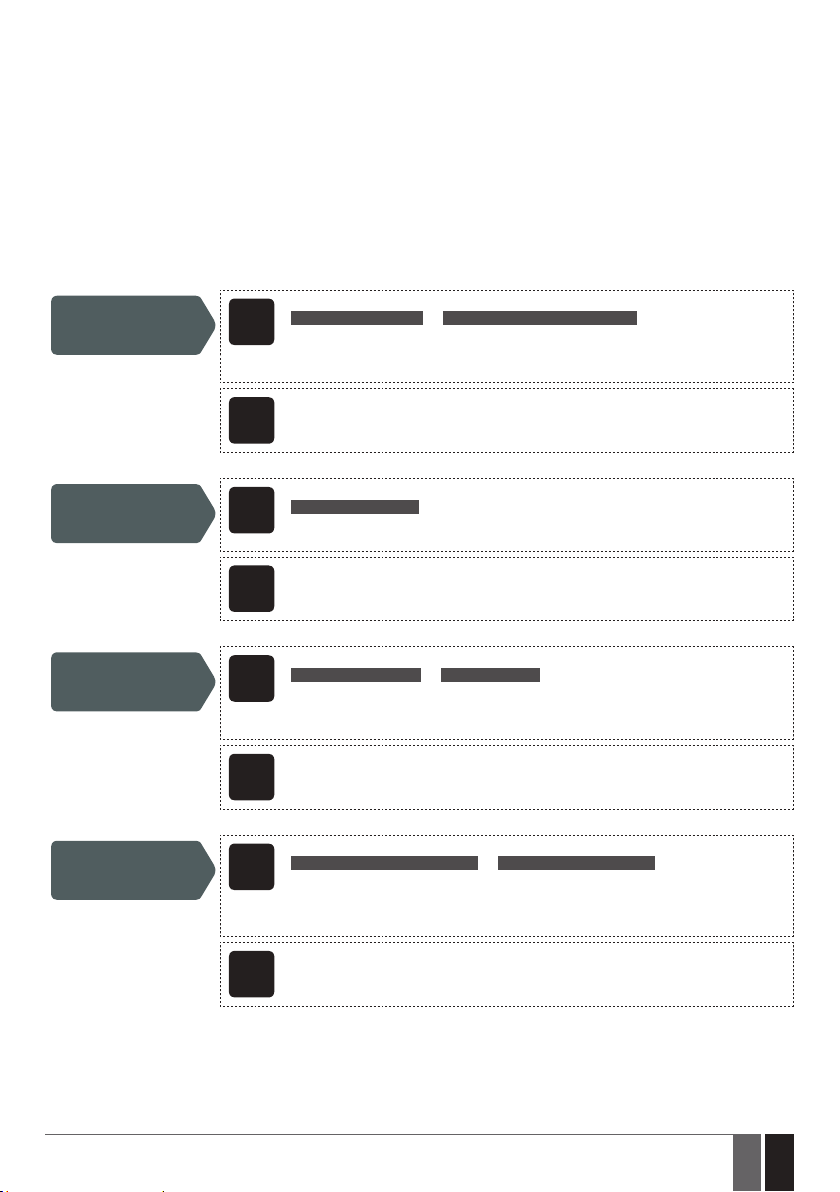
The system comes equipped with a user database of 2000 user capacity. When the phone number is set, the user will be able to control the
output (-s) by free of charge phone call. The user database allows to assign output C1, output C2 or both outputs (simultaneous control) to
a certain user. The supported phone number format is the following:
• International (w/o plus) – The phone numbers must be entered starting with an international country code in the following for-
mat: [international code][area code][local number], example for UK: 44170911XXXX1 .
User database supports user validity and access restriction features. For more details, please refer to 10.1. User Validity and Access
Restriction.
Optionally, a user name can be set that typically species the owner’s name of a certain phone number, for example: John.
The phone number and user name (if any) are used when searching for a certain user in the database as well as they are automatically
added in the event log after the successful output control event (see 13. EVENT LOG).
Add user phone
number (and user
name)
View user phone
numbers
Search for user by
phone number or
name
Assign output (-s) to
individual user
SMS
Cong
Tool
SMS
Cong
Tool
SMS
Cong
Tool
SMS
SMS text message content:
ssss_N:ttteeellnnuumm or ssss_N:ttteeellnnuumm:user-name
Value: ssss – 4-digit SMS password; ttteeellnnuumm – up to 15 digits user phone number;
user-name – up to 16 characters user name.
Example: 1111_N:44170911XXXX1:John
This operation may be carried out from the PC using the ELDES Conguration Tool software.
SMS text message content:
ssss_GETALLNUMBERS
Value: ssss – 4-digit SMS password.
Example: 1111_GETALLNUMBERS
This operation may be carried out from the PC using the ELDES Conguration Tool software.
SMS text message content:
ssss_T:ttteeellnnuumm or ssss_T:user-name
Value: ssss – 4-digit SMS password; ttteeellnnuumm – up to 15 digits user phone number;
user-name – up to 16 characters user name.
Example: 1111_T:John
This operation may be carried out from the PC using the ELDES Conguration Tool software.
SMS text message content:
ssss_OUTPUT_ttteeellnnuumm_o or ssss_OUTPUT_user-name_o
Value: ssss – 4-digit SMS password; ttteeellnnuumm – up to 15 digits user phone number;
o – output number; range - [1 – output C1; 2 – output C2; 3 – both outputs]; user-name – up
to 16 characters user name.
Example: 1111_OUTPUT_44170911XXXX1_2
Cong
ELDES GATE CONTROLLER ESIM120/320 User Manual v.1.1
This operation may be carried out from the PC using the ELDES Conguration Tool software.
Tool
13
13EN
Page 14
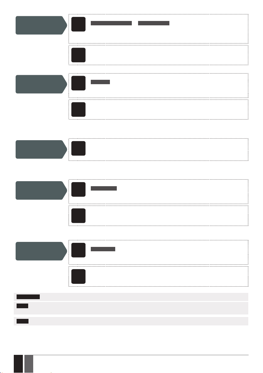
Delete individual user
SMS text message content:
ssss_D:ttteeellnnuumm or ssss_D:user-name
SMS
Value: ssss – 4-digit SMS password; ttteeellnnuumm – up to 15 digits user phone number;
user-name – up to 16 characters user name.
Example: 1111_D:John
Cong
Delete all users
Cong
The user database can be exported/imported to/from a .csv le for backup purposes or for a convenient user database management. To
export/import an existing user database, please refer to the following conguration method.
Export/import
existing user database
from/to le
By default, the user database is enabled and output control by all database users is permitted. To deny output control instead of deleting
all users from the database, please disable the user database using one of the following conguration methods.
Disable user database
Cong
Cong
This operation may be carried out from the PC using the ELDES Conguration Tool software.
Tool
SMS text message content:
ssss_D:ALL
SMS
Value: ssss – 4-digit SMS password.
Example: 1111_D:ALL
This operation may be carried out from the PC using the ELDES Conguration Tool software.
Tool
This operation may be carried out from the PC using the ELDES Conguration Tool software.
Tool
SMS text message content:
ssss_DBM_OFF
SMS
Value: ssss – 4-digit SMS password.
Example: 1111_DBM_OFF
This operation may be carried out from the PC using the ELDES Conguration Tool software.
Tool
To enable user database, please refer to the following conguration methods.
SMS text message content:
ssss_DBM_ON
Enable user database
ATTENTION: Space and colon characters are NOT allowed in the user names.
NOTE: Multiple users can be added by a single SMS text message, e. g. 1111_N:44170911XXXX1:John_ 44170911XXXX2:_ 44170911XXXX-
3:Tom
NOTE: Multiple users can be deleted by a single SMS text message, e. g. 1111_D:John_ 44170911XXXX3_Mark
For more details on output control, please refer to 11. OUTPUTS.
14
14 EN
SMS
Cong
Tool
Value: ssss – 4-digit SMS password.
Example: 1111_DBM_ON
This operation may be carried out from the PC using the ELDES Conguration Tool software.
ELDES GATE CONTROLLER ESIM120/320 User Manual v.1.1
Page 15
10.1. User Validity and Access Restriction
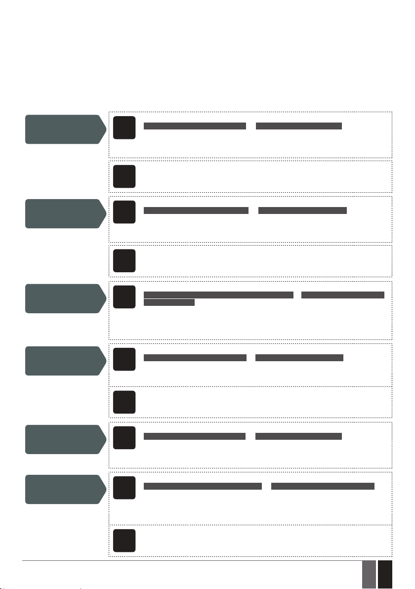
The system allows to restrict access in accordance with the scheduler assigned to a certain user. When one or more schedulers are assigned, the user will be able to control the output only on the specied weekdays and time set up in the scheduler. The system allows to
assign up to 8 dierent schedulers. For more details on how to set up the schedulers, please refer to 12. SCHEDULERS.
In addition, the system allows to limit the user validity by the following methods:
• Deadline (valid until) – When a specied date and time hits, the user will be automatically deleted from the database.
• Ring counter – When a specied number of phone calls to the system expires, the user will be automatically deleted from the data-
base.
SMS text message content:
Assign scheduler to
individual user
ssss_NSCHED_ttteeellnnuumm_c:ON or ssss_NSCHED_user-name_c:ON
SMS
Value: ssss – 4-digit SMS password; ttteeellnnuumm – up to 15 digits user phone number;
c – scheduler number; range – [1... 8]; user-name – up to 16 characters user name.
Example: 1111_NSCHED_John_5:ON
Remove scheduler
from individual user
Set deadline for
individual user
Remove deadline from
individual user
View set up deadline
for individual user
Cong
Tool
SMS
Cong
Tool
SMS
SMS
Cong
Tool
SMS
This operation may be carried out from the PC using the ELDES Conguration Tool software.
SMS text message content:
ssss_NSCHED_ttteeellnnuumm_c:OFF or ssss_NSCHED_user-name_c:OFF
Value: ssss – 4-digit SMS password; ttteeellnnuumm – up to 15 digits user phone number;
c – scheduler number; range – [1... 8]; user-name – up to 16 characters user name.
Example: 1111_NSCHED_John_5:OFF
This operation may be carried out from the PC using the ELDES Conguration Tool software.
SMS text message content:
ssss_EXPIRYTIME_ttteeellnnuumm_yyyy.mm.dd_hr:mn or ssss_EXPIRYTIME_user-name_
yyyy.mm.dd_hr:mn
Value: ssss – 4-digit SMS password; ttteeellnnuumm – up to 15 digits user phone number;
yyyy – year; mm – month, range – [01... 12]; dd – day, range – [01... 31]; hr – hours, range
– [00... 23]; mn – minutes, range – [00... 59]; user-name – up to 16 characters user name.
Example: 1111_EXPIRYTIME_John_2015.06.29_19:35
SMS text message content:
ssss_EXPIRYTIME_ttteeellnnuumm_0 or ssss_EXPIRYTIME_user-name_0
Value: ssss – 4-digit SMS password; ttteeellnnuumm – up to 15 digits user phone number;
user-name – up to 16 characters user name.
Example: 1111_EXPIRYTIME_44170911XXXX1_0
This operation may be carried out from the PC using the ELDES Conguration Tool software.
SMS text message content:
ssss_EXPIRYTIME_ttteeellnnuumm_? or ssss_EXPIRYTIME_user-name_?
Value: ssss – 4-digit SMS password; ttteeellnnuumm – up to 15 digits user phone number;
user-name – up to 16 characters user name.
Example: 1111_EXPIRYTIME_44170911XXXX1_?
SMS text message content:
Set ring counter for
individual user
Cong
ELDES GATE CONTROLLER ESIM120/320 User Manual v.1.1
ssss_RCOUNT_ttteeellnnuumm_numofcalls or ssss_RCOUNT_user-name_numofcalls
SMS
Value: ssss – 4-digit SMS password; ttteeellnnuumm – up to 15 digits administrator phone
number; user-name – up to 16 characters user name; numofcalls – number of phone calls,
range – [1... 4294967296].
Example: 1111_RCOUNT_44170911XXXX1_152
This operation may be carried out from the PC using the ELDES Conguration Tool software.
Tool
15
15EN
Page 16
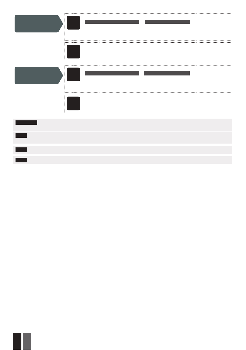
View set up ring
counter value for
individual user
SMS text message content:
ssss_RCOUNT_ttteeellnnuumm_? or ssss_RCOUNT_user-name_?
SMS
Value: ssss – 4-digit SMS password; ttteeellnnuumm – up to 15 digits administrator phone
number; user-name – up to 16 characters user name.
Example: 1111_RCOUNT_John_?
Cong
Remove ring counter
from individual user
Cong
ATTENTION: If the date and time are not set, the system will NOT be able to manage user validity and access. For more details on how
to set date and time, please refer to 9. DATE AND TIME.
NOTE: Multiple schedulers can be assigned/removed by a single SMS text message, e. g. 1111_NSCHED_
John_2:ON_6:OFF_3:OFF_5:ON
NOTE: 0 value removes the set up deadline from the user.
NOTE: 0 value removes the set up ring counter from the user.
This operation may be carried out from the PC using the ELDES Conguration Tool software.
Tool
SMS text message content:
ssss_RCOUNT_ttteeellnnuumm_0 or ssss_RCOUNT_user-name_0
SMS
Value: ssss – 4-digit SMS password; ttteeellnnuumm – up to 15 digits administrator phone
number; user-name – up to 16 characters user name.
Example: 1111_RCOUNT_John_0
This operation may be carried out from the PC using the ELDES Conguration Tool software.
Tool
16
16 EN
ELDES GATE CONTROLLER ESIM120/320 User Manual v.1.1
Page 17
11. OUTPUTS
The system comes equipped with 2 built-in outputs. The output is intended for connection and control of the gate automation device by
the following methods:
• Free of charge phone call from the user or administrator phone number (see 11.2. Output Control by Free of Charge Phone Call).
• SMS text message from the administrator phone number (see 11.3. Output Control by SMS Text Message).
• Automatically in accordance with the scheduled weekdays and time (see 11.6. Automatic Output Control).
• ELDES Cloud Services via browser or by Android/iOS mobile application (see 21. ELDES CLOUD SERVICES).
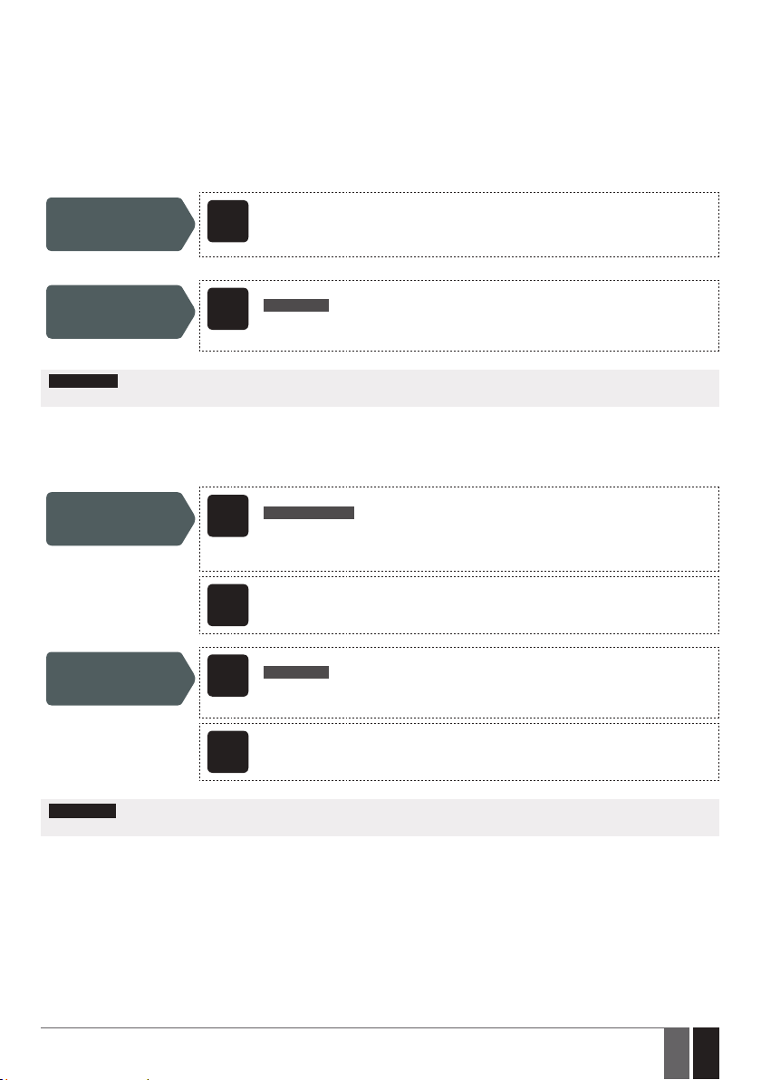
To set an output type, please refer to the following conguration method.
Set output as NO
(normally-open) or NC
(normally-closed)
The system allows to view the current output state by the following conguration method.
View output state
ATTENTION: Once the scheduler, set up for automatic output control comes into eect, the user/administrator will NOT be able to
control the output by phone call and SMS text message (see 11.6. Automatic Output Control).
11.1. Output Names
The outputs have names that can be customized. Typically, the name species a device type connected to a determined output, for example: Gate. The name can be used instead of output number when controlling the output by SMS text message.
By default, the output names are: C1 – Controll1, C2 – Controll2.
Set output name
View output name
Cong
Tool
SMS
SMS
Cong
Tool
SMS
This operation may be carried out from the PC using the ELDES Conguration Tool software.
SMS text message content:
ssss_STATUS
Value: ssss – 4-digit SMS password.
Example: 1111_STATUS
SMS text message content:
ssss_Co:out-name
Value: ssss – 4-digit SMS password; o – output number, range [1 – output C1; 2 – output C2];
out-name – up to 16 characters output name.
Example: 1111_C1:Gates
This operation may be carried out from the PC using the ELDES Conguration Tool software.
SMS text message content:
ssss_STATUS
Value: ssss – 4-digit SMS password.
Example: 1111_STATUS
Cong
ATTENTION: Space, colon, semi-colon characters, parameter names and/or values, such as PSW, STATUS, ON, OFF etc. are NOT allowed
in output names.
11.2. Output Control by Free of Charge Phone Call
To open or close the gate, dial the system’s phone number from any available user or administrator phone numbers (see 10. USER PHONE
NUMBER DATABASE and 8. ADMINISTRATOR PHONE NUMBERS for phone number management). The phone call is free charge as the
system rejects it and turns ON/OFF the output (-s) for the listed time period (pulse; by default – 2 seconds) resulting in the gate opening or
closing, depending on the current gate state and selected output type NO or NC. If there is more than one listed caller dialing to the system
at the same time, the system will accept the incoming call from the caller who was the rst to dial while other caller (-s) will be ignored.
The system supports a conrmation phone call to user/administrator phone number. For more details, please refer to 11.4. Output Con-
trol Conrmation by Call Back
ELDES GATE CONTROLLER ESIM120/320 User Manual v.1.1
This operation may be carried out from the PC using the ELDES Conguration Tool software.
Tool
17
17EN
Page 18
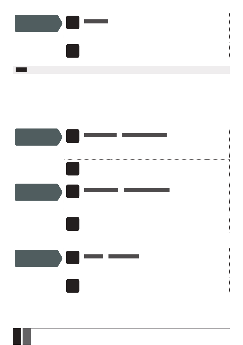
Set output pulse
duration
SMS text message content:
ssss_TIMERo:pl
SMS
Value: ssss – 4-digit SMS password; o – output number, range [1 – output C1; 2 – output C2];
pl – pulse duration, range – [1... 10] seconds.
Example: 1111_TIMER2:4
Cong
NOTE: ELDES Conguration Tool software allows to set the unlimited output pulse duration value.
11.3. Output Control by SMS Text Message
To open or close the gate, send the SMS text message from any of 5 available administrator phone numbers (see 10. USER PHONE NUMBER DATABASE for phone number management). The system will turn ON the output (-s) for a determined time period (pulse) resulting
in the gate opening or closing, depending on the current gate state. The conrmation reply by SMS text message, containing the output
name (see 11.1. Output Names), will be sent to the administrator phone number that the output control by SMS text message was initiated from.
To instantly turn ON/OFF the output and set its state to ON/OFF when the system starts-up, please refer to the following conguration
methods.
Turn ON output for
time period
Cong
Turn OFF output for
time period
This operation may be carried out from the PC using the ELDES Conguration Tool software.
Tool
SMS text message content:
ssss_Co:ON:hr.mn.sc or ssss_out-name:ON:hr.mn.sc
SMS
Value: ssss – 4-digit SMS password; o – output number, range - [1... 2]; hr – hours, range –
[00... 23]; mn – minutes, range – [00... 59]; sc – seconds, range – [00... 59]; out-name – up
to 16 characters output name.
Example: 1111_C2:ON:00.00.09
This operation may be carried out from the PC using the ELDES Conguration Tool software.
Tool
SMS text message content:
ssss_Co:OFF:hr.mn.sc or ssss_out-name:OFF:hr.mn.sc
SMS
Value: ssss – 4-digit SMS password; o – output number, range - [1... 2]; hr – hours, range –
[00... 23]; mn – minutes, range – [00... 59]; sc – seconds, range – [00... 59]; out-name – up
to 16 characters output name.
Example: 1111_C1:OFF:00.11.49
Cong
To instantly turn ON/OFF the specied output and set its state to ON/OFF when the system starts-up, please refer to the following conguration methods.
Turn ON output/Set
output start-up state
as ON
Cong
18
18 EN
This operation may be carried out from the PC using the ELDES Conguration Tool software.
Tool
SMS text message content:
ssss_Co:ON or ssss_out-name:ON
SMS
Value: ssss – 4-digit SMS password; o – output number, range - [1... 2]; out-name – up to 16
characters output name.
Example: 1111_C1:ON
This operation may be carried out from the PC using the ELDES Conguration Tool software.
Tool
ELDES GATE CONTROLLER ESIM120/320 User Manual v.1.1
Page 19
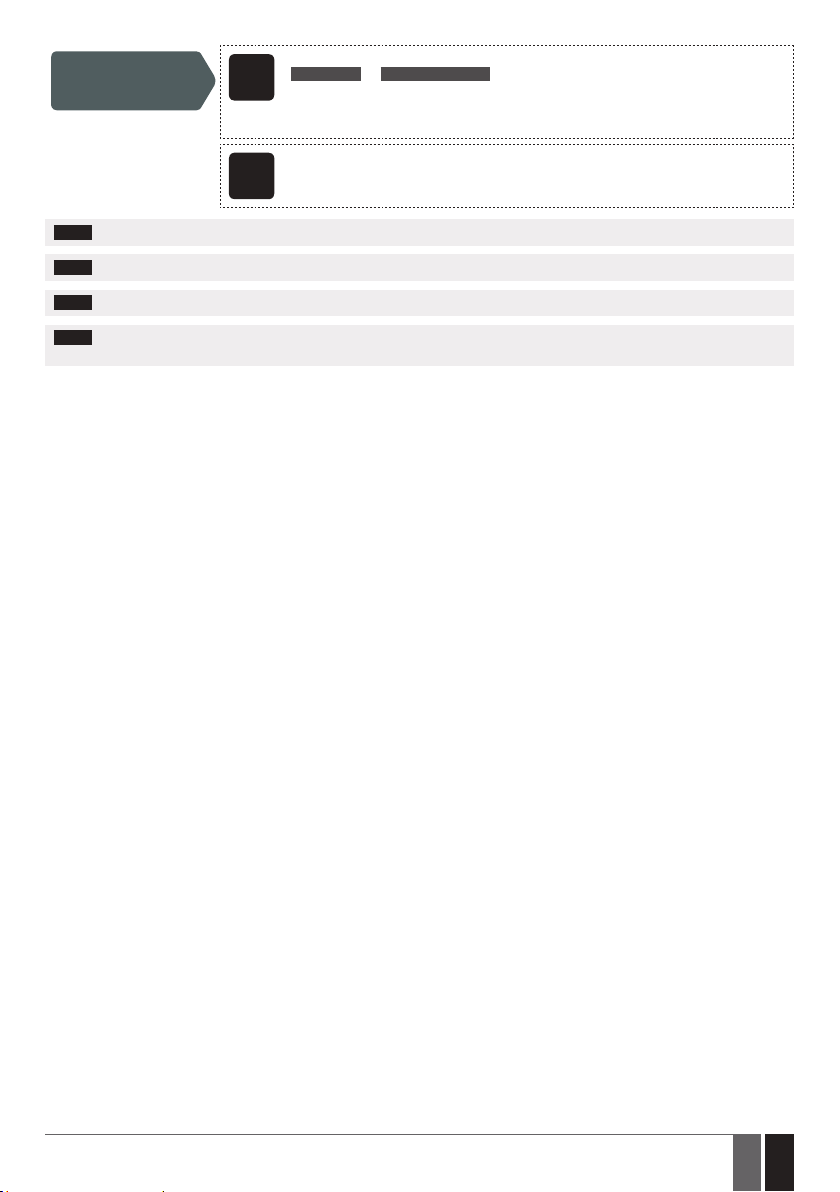
Turn OFF output/Set
output start-up state
as OFF
SMS text message content:
ssss_Co:OFF or ssss_out-name:OFF
SMS
Value: ssss – 4-digit SMS password; o – output number, range - [1... 2]; out-name – up to
16 characters output name.
Example: 1111_C2:OFF
Cong
NOTE: Output can be turned ON for a determined time period only when it is in OFF state.
NOTE: Output can be turned OFF for a determined time period only when it is in ON state.
NOTE: ELDES Conguration Tool software allows to set only the output start-up state.
NOTE: The administrator can control any output by SMS text message regardless of the output assigned to the administrator phone number
(see 8. ADMINISTRATOR PHONE NUMBERS).
This operation may be carried out from the PC using the ELDES Conguration Tool software.
Tool
ELDES GATE CONTROLLER ESIM120/320 User Manual v.1.1
19
19EN
Page 20
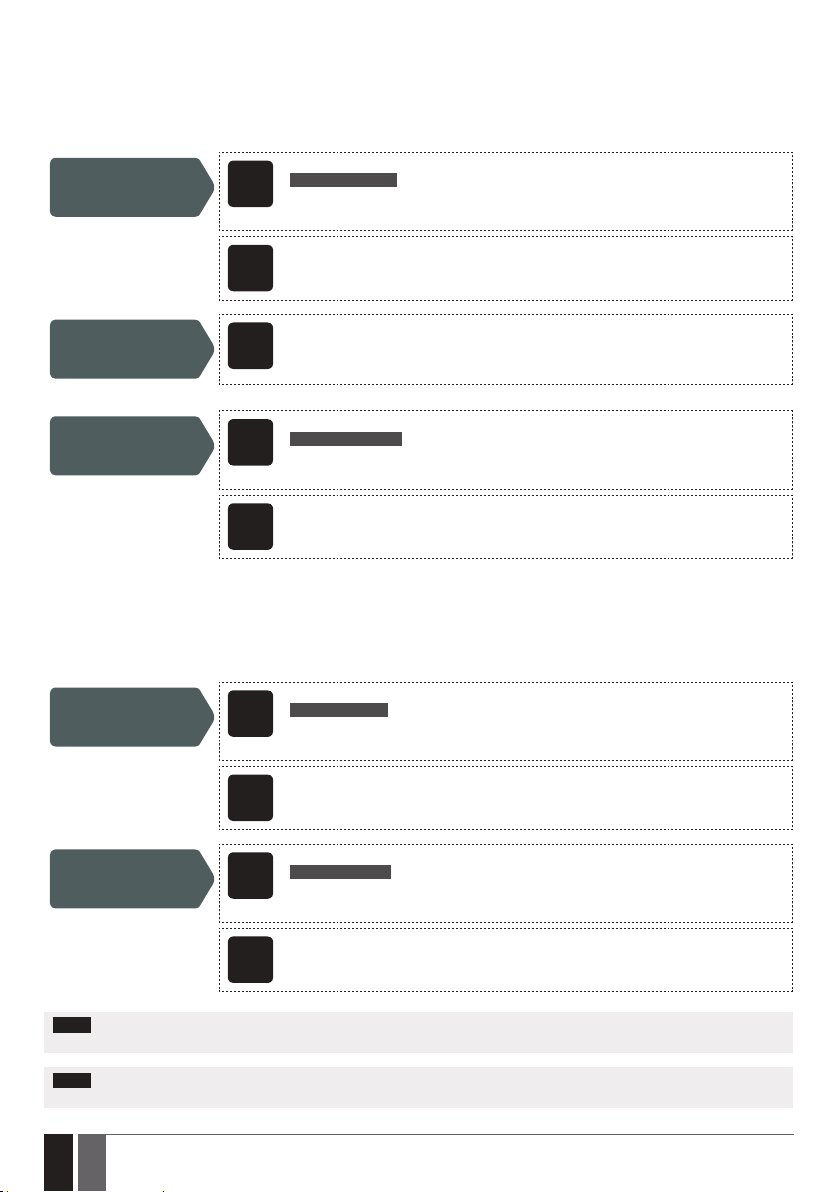
11.4. Output Control Conrmation by Call Back
The system can make a phone call conrming that the output control action has been successfully carried out. Once enabled, every output
control action will be followed by a 5-second (by default) ring to the user/administrator phone number that the output control by free of
charge phone call was initiated from.
By default, output control conrmation by call back is disabled. To enable/disable it, please refer to the following conguration methods.
Enable output control
conrmation by call
back
SMS text message content:
ssss_CALLBACK:ON
SMS
Value: ssss – 4-digit SMS password.
Example: 1111_CALLBACK:ON
Cong
Set call back duration
Disable output
control conrmation
by call back
11.5. Output Control from any Phone Number
Once an administrator phone number is listed, the system will ignore any incoming calls from a non-listed phone number. To permit/deny
output control by free of charge phone call (see 11. OUTPUTS) from a non-listed phone number, please refer to the following conguration methods.
Enable output control
from any phone
number
Cong
Cong
Cong
This operation may be carried out from the PC using the ELDES Conguration Tool software.
Tool
This operation may be carried out from the PC using the ELDES Conguration Tool software.
Tool
SMS text message content:
ssss_CALLBACK:OFF
SMS
Value: ssss – 4-digit SMS password.
Example: 1111_CALLBACK:OFF
This operation may be carried out from the PC using the ELDES Conguration Tool software.
Tool
SMS text message content:
ssss_ALLNUM:ON
SMS
Value: ssss – 4-digit SMS password.
Example: 1111_ALLNUM:ON
This operation may be carried out from the PC using the ELDES Conguration Tool software.
Tool
Disable output
control from any
phone number
Cong
NOTE: The system will accept SMS text messages only from a listed administrator phone number even if output control from any
phone number is enabled.
NOTE: Once the output control from any phone number is enabled, a non-listed phone number user will be able to control outputs C1 and
C2.
20
20 EN
SMS text message content:
ssss_ALLNUM:OFF
SMS
Value: ssss – 4-digit SMS password.
Example: 1111_ALLNUM:OFF
This operation may be carried out from the PC using the ELDES Conguration Tool software.
Tool
ELDES GATE CONTROLLER ESIM120/320 User Manual v.1.1
Page 21
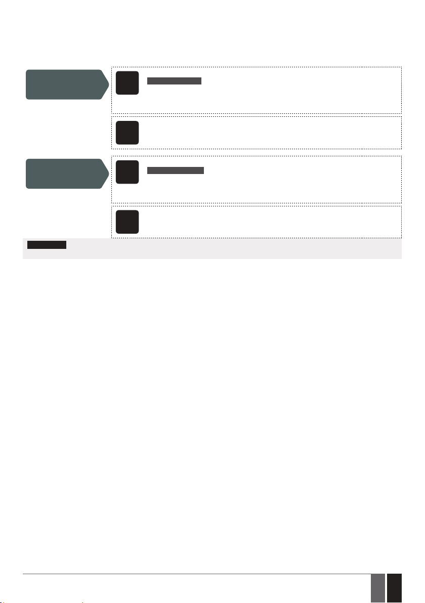
11.6. Automatic Output Control
The system comes equipped with automatic output control in accordance with the assigned scheduler (-s). When one or more schedulers
are assigned, the output will automatically turn ON/OFF on the specied weekdays and time set up in the scheduler. The system allows to
assign up to 8 dierent schedulers. For more details on how to set up the schedulers, please refer to 12. SCHEDULERS.
SMS text message content:
ssss_OSHEDo_c:ON
Assign scheduler
SMS
Value: ssss – 4-digit SMS password; o – output number, range [1 – output C1; 2 – output C2];
c – scheduler number; range – [1... 8].
Example: 1111_OSCHED2_1:ON
Cong
Remove scheduler
Cong
ATTENTION: Once the scheduler, set up for automatic output control, comes into eect, the user/administrator will NOT be able to
control the output by phone call and SMS text message.
This operation may be carried out from the PC using the ELDES Conguration Tool software.
Tool
SMS text message content:
ssss_OSHEDo_c:OFF
SMS
Value: ssss – 4-digit SMS password; o – output number, range [1 – output C1; 2 – output C2];
c – scheduler number; range – [1... 8].
Example: 1111_OSCHED1_5:OFF
This operation may be carried out from the PC using the ELDES Conguration Tool software.
Tool
ELDES GATE CONTROLLER ESIM120/320 User Manual v.1.1
21
21EN
Page 22
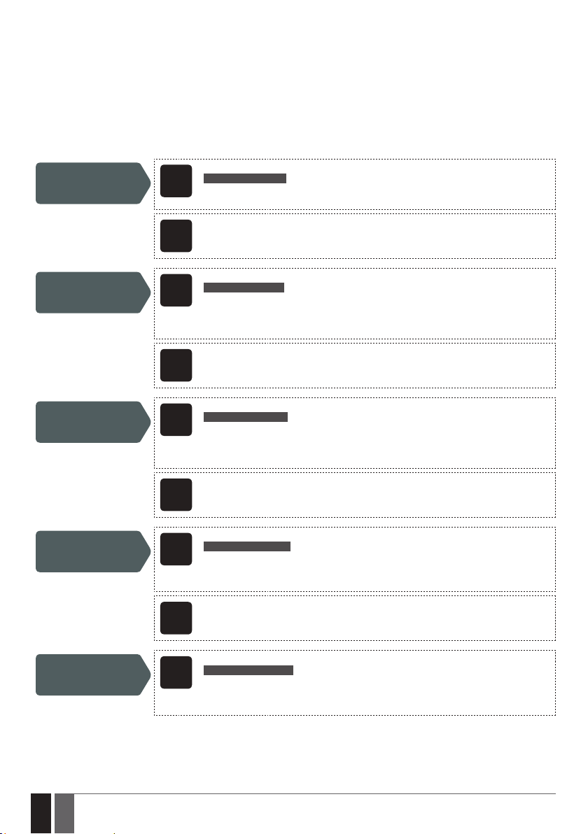
12. SCHEDULERS
The system comes equipped with 8 schedulers that allow to set up the day (-s) of the week and time parameters. The schedulers are used
to set up user validity and access restriction (see 10.1. User Validity and Access Restriction) as well as automatic output control (see
11.6. Automatic Output Control). Each scheduler includes the following parameters:
• Every Day – Determines whether the scheduler will be valid everyday regardless of the current day of the week.
• At Specied Day (-s) – Determines day (-s) in the week when the scheduler is to be valid.
• Start Time – Determines the point in time when the scheduler is to take eect.
• End Time – Determines the point in time when the scheduler is to cease to take eect.
SMS text message content:
Select At Specied
Day (-s)
ssss_SCHEDc_AL:OFF
SMS
Value: ssss – 4-digit SMS password; c – scheduler number; range – [1... 8].
Example: 1111_SCHED4_AL:OFF
Enable day (-s) of the
week
Disable day (-s) of the
week
Set start time
Cong
Tool
SMS
Cong
Tool
SMS
Cong
Tool
SMS
Cong
Tool
This operation may be carried out from the PC using the ELDES Conguration Tool software.
SMS text message content:
ssss_SCHEDc_wd:ON
Value: ssss – 4-digit SMS password; c – scheduler number; range – [1... 8]; wd – weekday,
range – [MO – Monday; TU – Tuesday; WE – Wednesday; TH – Thursday; FR – Friday; SA –
Saturday; SU – Sunday].
Example: 1111_SCHED6_FR:ON
This operation may be carried out from the PC using the ELDES Conguration Tool software.
SMS text message content:
ssss_SCHEDc_wd:OFF
Value: ssss – 4-digit SMS password; c – scheduler number; range – [1... 8]; wd – weekday,
range – [MO – Monday; TU – Tuesday; WE – Wednesday; TH – Thursday; FR – Friday; SA –
Saturday; SU – Sunday].
Example: 1111_SCHED4_SU:OFF
This operation may be carried out from the PC using the ELDES Conguration Tool software.
SMS text message content:
ssss_SCHEDc_st:hr:mn
Value: ssss – 4-digit SMS password; c – scheduler number; hr – hours, range – [00... 23];
mn – minutes, range – [00... 59].
Example: 1111_SCHED2_ST:20:25
This operation may be carried out from the PC using the ELDES Conguration Tool software.
Set end time
22
22 EN
SMS text message content:
ssss_SCHEDc_en:hr:mn
SMS
Value: ssss – 4-digit SMS password; c – scheduler number; hr – hours, range – [00... 23];
mn – minutes, range – [00... 59].
Example: 1111_SCHED8_EN:09:12
ELDES GATE CONTROLLER ESIM120/320 User Manual v.1.1
Page 23
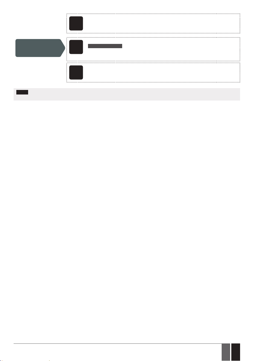
Select Every Day
Cong
Tool
SMS
This operation may be carried out from the PC using the ELDES Conguration Tool software.
SMS text message content:
ssss_SCHEDc_AL:ON
Value: ssss – 4-digit SMS password; c – scheduler number, range – [1... 8]
Example: 1111_SCHED1_AL:ON
Cong
NOTE: Multiple scheduler parameters can be congured by a single SMS text message, e. g. 1111_SCHED2_MO:ON_FR:OFF_ EN:20:18_
TH:OFF_ST:15:25_TU:ON_AL:OFF
This operation may be carried out from the PC using the ELDES Conguration Tool software.
Tool
ELDES GATE CONTROLLER ESIM120/320 User Manual v.1.1
23
23EN
Page 24
13. EVENT LOG
This feature allows to chronologically register up to 1000 timestamped records regarding the following system events:
• Output control including the user/administrator phone number and user name.
• User validity expiry by deadline.
• User validity expiry by ring counter.
• Automatic output control beginning.
• Automatic output control ending.
To export the event log to .log le or clear it, please refer to the following conguration methods.
Export event log
By default, when the event log reaches the 1000 record limit, the system will send the notication by SMS text message to the administrator phone number. To clear the event log and/or disable/enable the notication regarding the full event log, please refer to the following
conguration methods.
Clear event log
Disable Log Full
notication
Enable Log Full
notication
By default, the event log is set as of LIFO ( last in, rst out) type that allows the system to automatically replace the oldest records with the
the latest ones.. To disable/enable it, please refer to the following conguration methods.
Cong
Cong
Cong
Cong
This operation may be carried out from the PC using the ELDES Conguration Tool software.
Tool
SMS text message content:
ssss_DELETELOG
SMS
Value: ssss – 4-digit SMS password.
Example: 1111_DELETELOG
This operation may be carried out from the PC using the ELDES Conguration Tool software.
Tool
This operation may be carried out from the PC using the ELDES Conguration Tool software.
Tool
This operation may be carried out from the PC using the ELDES Conguration Tool software.
Tool
Disable LIFO type log
Enable LIFO type log
24
24 EN
Cong
Tool
Cong
Tool
This operation may be carried out from the PC using the ELDES Conguration Tool software.
This operation may be carried out from the PC using the ELDES Conguration Tool software.
ELDES GATE CONTROLLER ESIM120/320 User Manual v.1.1
Page 25
14. INPUTS
The system comes equipped with 3 inputs designed for fault indication output or detection device connection, such as door contacts. Once
a fault indication output and/or a detection device is triggered, the system will send a notication to the administrator phone number.
Typically, the inputs are used to receive notications regarding jammed gate or gate state. For more details, please refer to 14.1. Input
Names and Alarm Notications.
Each input’s sensitivity level can be customized by a delay time (by default – 600 milliseconds). If an input is left triggered until the delay
time expires, the input is considered violated.
SMS text message content:
ssss_Tn:in-delay
Set input delay
SMS
Value: ssss – 4-digit SMS password; n – input number, range – [1... 3]; in-delay – input
delay, range – [100... 42000000] milliseconds.
Example: 1111_T3:10500
Cong
The system allows to view the current input state by the following conguration method.
View input state
14.1. Input Names and Alarm Notications
Each input has a name that can be customized. Typically, the name species a device type connected to a certain input terminal, for example: GateOpen. The input names are used in notications that are sent by SMS text message to the administrator regarding the input alarm
event. By default, the input names are: Z1 – zone1, Z2 – zone2, Z3 – zone3.
Set input name
Cong
View input names
This operation may be carried out from the PC using the ELDES Conguration Tool software.
Tool
SMS text message content:
ssss_INFO
SMS
Value: ssss – 4-digit SMS password;
Example: 1111_INFO
SMS text message content:
ssss_Zn:input-name
SMS
Value: ssss – 4-digit SMS password; n – input number, range – [1... 3]; input-name – up to
8 characters input name.
Example: 1111_Z2:GateOpen
This operation may be carried out from the PC using the ELDES Conguration Tool software.
Tool
SMS text message content:
ssss_STATUS
SMS
Value: ssss – 4-digit SMS password.
Example: 1111_STATUS
Cong
By default, the system sends SMS text message to the rst available administrator in case of input alarm. If the system did not receive the
SMS delivery report during 20 seconds, it will attempt to send the SMS text message to the next listed administrator phone number. To
ignore the SMS delivery report and allow/disallow the system to send the SMS text message to every listed administrator phone number,
please refer to the following conguration methods.
ELDES GATE CONTROLLER ESIM120/320 User Manual v.1.1
This operation may be carried out from the PC using the ELDES Conguration Tool software.
Tool
25
25EN
Page 26
Enable notication
to all listed
administrator phone
numbers in case of
input alarm
SMS
Cong
Tool
SMS text message content:
ssss_SMSALL:ON
Value: ssss – 4-digit SMS password.
Example: 1111_SMSALL:ON
This operation may be carried out from the PC using the ELDES Conguration Tool software.
Disable notication
to all listed
administrator phone
numbers in case of
input alarm
Cong
ATTENTION: Space characters, parameter values, such as ON, OFF etc. are NOT allowed in the input names. Space characters,parame-
ter values, such as ON, OFF etc. are NOT allowed in the input names.
For more details on how to disable the input alarm notications, please refer to 14.2. Disabling and Enabling Inputs.
For more details on the algorithm of how the system sends the notications, please refer to 16. SYSTEM NOTIFICATIONS.
14.2. Disabling and Enabling Inputs
By default, all inputs are enabled. Once disabled, input alarm event will no longer be followed by an SMS text message. To disable/enable
an individual input, please refer to the following conguration methods.
Disable input
Cong
Enable input
SMS text message content:
ssss_SMSALL:OFF
SMS
Value: ssss – 4-digit SMS password.
Example: 1111_SMSALL:OFF
This operation may be carried out from the PC using the ELDES Conguration Tool software.
Tool
SMS text message content:
ssss_Zn:OFF
SMS
Value: ssss – 4-digit SMS password; n – input number, range – [1... 3]; input-name – up to
8 characters input name.
Example: 1111_Z3:OFF
This operation may be carried out from the PC using the ELDES Conguration Tool software.
Tool
SMS text message content:
ssss_Zn:ON
SMS
Value: ssss – 4-digit SMS password; n – input number, range – [1... 3]; input-name – up to
8 characters input name.
Example: 1111_Z2:ON
View input status
26
26 EN
Cong
Tool
SMS
Cong
Tool
This operation may be carried out from the PC using the ELDES Conguration Tool software.
SMS text message content:
ssss_STATUS
Value: ssss – 4-digit SMS password.
Example: 1111_STATUS
This operation may be carried out from the PC using the ELDES Conguration Tool software.
ELDES GATE CONTROLLER ESIM120/320 User Manual v.1.1
Page 27
15. SYSTEM INFORMATION. INFO SMS
The system supports an informational SMS text message identied as the Info SMS, which can be delivered upon request. Once requested,
the system will reply with Info SMS that provides the following:
• System date and time.
• Signal strength.
• Number of occupied and empty slots in the user database.
• State of inputs (OK/alarm).
SMS text message content:
Request system
information
ssss_INFO
SMS
Value: ssss – 4-digit SMS password.
Example: 1111_INFO
Cong
For more details on the algorithm of how the system sends the notications, please refer to 16. SYSTEM NOTIFICATIONS.
15.1. Periodic Info SMS
The system may send the Info SMS to the administrator phone number periodically. By default, the period is daily at 11:00 (frequency – 1
day; time – 11). The minimum period is every 1 hour (frequency – 0 days; time – 1). Typically, this feature is used to verify the operation
status of the system.
To enable periodic Info SMS by setting the frequency and time or disable it, please refer to the following conguration methods.
Set periodic Info SMS
frequency and time
Cong
Disable periodic Info
SMS
Cong
This operation may be carried out from the PC using the ELDES Conguration Tool software.
Tool
SMS text message content:
ssss_INFO:f:it
SMS
Value: ssss – 4-digit SMS password; f – frequency, range – [00... 99] days; it – time, range
– [01... 23].
Example: 1111_INFO:3.15
This operation may be carried out from the PC using the ELDES Conguration Tool software.
Tool
SMS text message content:
ssss_INFO:00:00
SMS
Value: ssss – 4-digit SMS password.
Example: 1111_INFO:00.00
This operation may be carried out from the PC using the ELDES Conguration Tool software.
Tool
ELDES GATE CONTROLLER ESIM120/320 User Manual v.1.1
27
27EN
Page 28
16. SYSTEM NOTIFICATIONS
In case of a certain event, the system attempts to send an SMS text message to the rst listed administrator phone number only. If the
administrator phone number is unavailable and the system fails to receive the SMS delivery report within 20 seconds, it will attempt to
send the SMS text message to the next listed administrator phone number. The administrator phone number may be unavailable due to
the following reasons:
• Mobile phone was switched o.
• Was out of signal coverage.
The system will continue sending the SMS text message to the next listed administrator phone numbers in the priority order until one is
available. The system sends the SMS text message only once and will not return to the rst administrator phone number if the last one
was unavailable.
16.1. SMS Text Message Delivery Restrictions
By default, the system is restricted to send out up to 25 SMS text messages daily and up to 400 SMS text messages monthly. To change the
limits or disable SMS text message delivery restrictions, please refer to the following conguration method.
Manage SMS text
message delivery
limits
When the daily or monthly SMS text message delivery limit is exceeded, the system will notify the administrator by SMS text message. The
limit counter will automatically reset once the date and time synchronization period takes eect (by default - every 30 days). Alternatively,
you can reset the limits by referring to the following conguration method.
Reset SMS text
message delivery limit
counter
NOTE: 0 value disables daily/monthly SMS text message delivery restrictions.
See also 9.1. Automatic Date and Time Synchronization.
16.2. SMSC (Short Message Service Center) Phone Number
An SMS center (SMSC) is a network element, which routes SMS text messages to the destination recipient and stores the SMS text message
if the recipient is unavailable. Typically, the phone number of the SMS center is already stored in the SIM card provided by operator. If the
administrator fails to receive replies from the system, the SMS center phone number, provided by operator, must be set manually.
Set SMSC phone
number
ATTENTION: Before setting the SMSC phone number, please check the credit balance of the system’s SIM card. The system will fail to
reply if the credit balance is insucient.
Cong
Tool
SMS
SMS
This operation may be carried out from the PC using the ELDES Conguration Tool software.
SMS text message content:
ssss_REMOVEBAN
Value: ssss – 4-digit SMS password.
Example: 1111_REMOVEBAN
SMS text message content:
ssss_SMS_+ttteeellnnuumm
Value: ssss – 4-digit SMS password; ttteeellnnuumm – up to 15 digits SMSC phone number.
Example: 1111_SMS_+44170311XXXX1
28
28 EN
ELDES GATE CONTROLLER ESIM120/320 User Manual v.1.1
Page 29
17. GPRS NETWORK SETTINGS
The GPRS network settings are used for device communication with the remote conguration server or ELDES Cloud Services server via
GPRS connection. To set the GPRS network settings, please refer to the following conguration methods.
SMS text message content:
ssss_SETGPRS:APN:acc-point-name
Set APN
SMS
Value: ssss – 4-digit SMS password; acc-point-name – up to 31 character APN (Access
Point Name) provided by the operator.
Example: 1111_SETGPRS:APN:internet
Set user name
Set password
View GPRS network
settings
Cong
Tool
SMS
Cong
Tool
SMS
Cong
Tool
SMS
Cong
Tool
This operation may be carried out from the PC using the ELDES Conguration Tool software.
SMS text message content:
ssss_SETGPRS:USER:usr-name
Value: ssss – 4-digit SMS password; usr-name – up to 31 character user name provided by
the operator.
Example: 1111_SETGPRS:USER:mobileusr
This operation may be carried out from the PC using the ELDES Conguration Tool software.
SMS text message content:
ssss_SETGPRS:PSW:password
Value: ssss – 4-digit SMS password; password – up to 31 character password provided by
the operator.
Example: 1111_SETGPRS:PSW:mobilepsw
This operation may be carried out from the PC using the ELDES Conguration Tool software.
SMS text message content:
ssss_SETGPRS?
Value: ssss – 4-digit SMS password.
Example: 1111_SETGPRS?
This operation may be carried out from the PC using the ELDES Conguration Tool software.
NOTE: Multiple parameters can be set by single SMS text message, e. g. 1111_SETGPRS:APN:internet;USER:mobileusr;PSW:mobilepsw
ELDES GATE CONTROLLER ESIM120/320 User Manual v.1.1
29
29EN
Page 30
18. INCOMING PHONE NUMBER VERIFICATION SETTINGS
ATTENTION: Due to security reasons it is NOT recommended to congure the parameters described below.
The system comes equipped with a phone number length verication feature allowing to restrict access for the phone numbers of a certain
length. By default, the system supports the administrator and user phone numbers consisting of at least 4 digits (minimum phone number
length), while the last 7 digits of the caller’s phone number are used for comparison with the listed phone number in order to identify
whether the phone number is listed. By default, the system will ignore all phone numbers consisting of less than 4 digits even if the phone
number is listed as the administrator phone number or the user phone number. However, the system will accept all incoming phone calls
containing a phone number matching the last 7 digits of the listed phone number.
Manage incoming
phone number
verication settings
Cong
Tool
This operation may be carried out from the PC using the ELDES Conguration Tool software.
19. REMOTE SYSTEM RESTART
In some critical situations, a system restart may be required. To remotely carry out system restart, please refer to the following conguration method.
SMS text message content:
ssss_RESTART
Restart the system
SMS
Value: ssss – 4-digit SMS password.
Example: 1111_RESTART
30
30 EN
ELDES GATE CONTROLLER ESIM120/320 User Manual v.1.1
Page 31

20. TECHNICAL SUPPORT
20.1. Troubleshooting
Indication Possible reason
Indicators SIM STAT and NETW are OFF · No mains power
Indicator SIM STAT is ON · Missing SIM card
Indicator SIM STAT is ashing · Connection fault
· Wrong wiring
· Blown fuse
· Disconnected antenna
· Micro-controller could not start due to electrical mains noise or static discharge
· PIN code is enabled
· SIM card is inactive
Unable to receive any SMS text messages to
the administrator phone number or control the
output
Unable to connect to the device remotely via
GPRS connection
Received SMS text message “Wrong syntax” · Incorrect SMS text message structure
For product warranty repair service, please contact your local retail store where this product was purchased.
If your problem could not be xed by the self-guide above, please contact your local distributor. More up to date information about your
device and other products can be found at the manufacturer’s website eldesalarms.com
20.2. Restoring Default Parameters
1. Power down the device.
2. Short-circuit (connect) the DEF pins.
3. Power up the device for 7 seconds.
4. Power down the device.
5. Remove the short-circuit from DEF pins.
6. Parameters restored to default.
20.3. Updating the Firmware via USB Cable
1. Power down the device.
2. Short-circuit (connect) the DEF pins.
3. Connect the device via USB cable to the PC.
4. Power up the device.
5. The new window must pop-up where you will nd the .bin le. Otherwise open My Computer and look for Boot Disk drive.
6. Delete the .bin le found in the drive.
7. Copy the new rmware .bin le to the very same window.
8. Power down the device.
9. Unplug the USB cable.
10. Remove the short-circuit from DEF pins.
11. Power up the device.
12. Firmware updated.
NOTE: It is strongly recommended to restore default parameters after the rmware update.
· Insucient SIM card credit balance
· Caller's phone number is set up as withheld (hidden)
· No network signal
· Wrong administrator/user phone number
· Administrator/user phone number is not set
· SIM card was replaced before disconnecting mains power
· Incorrect SMS center phone number
· GPRS settings (APN, user name, password) not set.
· Insucient SIM card credit balance
· Mobile internet service (GPRS) not activated on the SIM card.
· Unnecessary space character might have been typed in SMS text message
ELDES GATE CONTROLLER ESIM120/320 User Manual v.1.1
31
31EN
Page 32
21. ELDES CLOUD SERVICES
ATTENTION: When remote connection session is initialized (i.e. when you send an SMS text command and receive the answer from the
system), then ELDES Cloud Services feature will NOT work and becomes inaccessible until the remote connection session is over.
ELDES Cloud Services is a cloud-based platform providing a user-friendly graphical interface intended for system status monitoring and
control:
• Control the gates or any other electrical appliance connected to the output
• Congure the system remotely via web-browser
The connection with the platform can be established either via GPRS network and can be accessed via web browser and smart-phone
application developed for Android and iOS-based devices (iPhone, iPad).
In order to start using ELDES Cloud Services platform, please enable it using the following conguration methods.
SMS text message content:
Enable ELDES Cloud
Services
ssss_SMART:ON
SMS
Value: ssss - 4-digit SMS password.
Example: 1111_SMART:ON
Cong
Once enabled, visit https://security.eldes.lt and create your personal account. Then log in to your ELDES Cloud Services account and add a
device by following the step-by-step instructions provided in ELDES Cloud Services website. When adding the device to your account, you
will be prompted for Cloud Services ID, which can be obtained using ELDES Conguration Tool software or by sending the following SMS
text message to the system’s phone number.
Request for ELDES
Cloud Services ID
Cong
To disable ELDES Cloud Services, please refer to the following conguration methods.
Disable ELDES Cloud
Services
Cong
ATTENTION: In case you DO NOT wish to use ELDES Cloud Services and your device is not associated with any ELDES Cloud Services
account, please DO NOT leave ELDES Cloud Services enabled. Otherwise, additional charges may apply for data trac based on your cell
phone service plan.
NOTE: Additional charges may apply for data trac based on your cell phone service plan when using ELDES Cloud Services platform.
This operation may be carried out from the PC using the ELDES Conguration Tool
Tool
software.
SMS text message content:
ssss_SMART_ID
SMS
Value: ssss - 4-digit SMS password.
Example: 1111_SMART_ID
This operation may be carried out from the PC using the ELDES Conguration Tool
Tool
software.
SMS text message content:
ssss_SMART:OFF
SMS
Value: ssss - 4-digit SMS password.
Example: 1111_SMART:OFF
This operation may be carried out from the PC using the ELDES Conguration Tool
Tool
software.
32
32 EN
ELDES GATE CONTROLLER ESIM120/320 User Manual v.1.1
Page 33
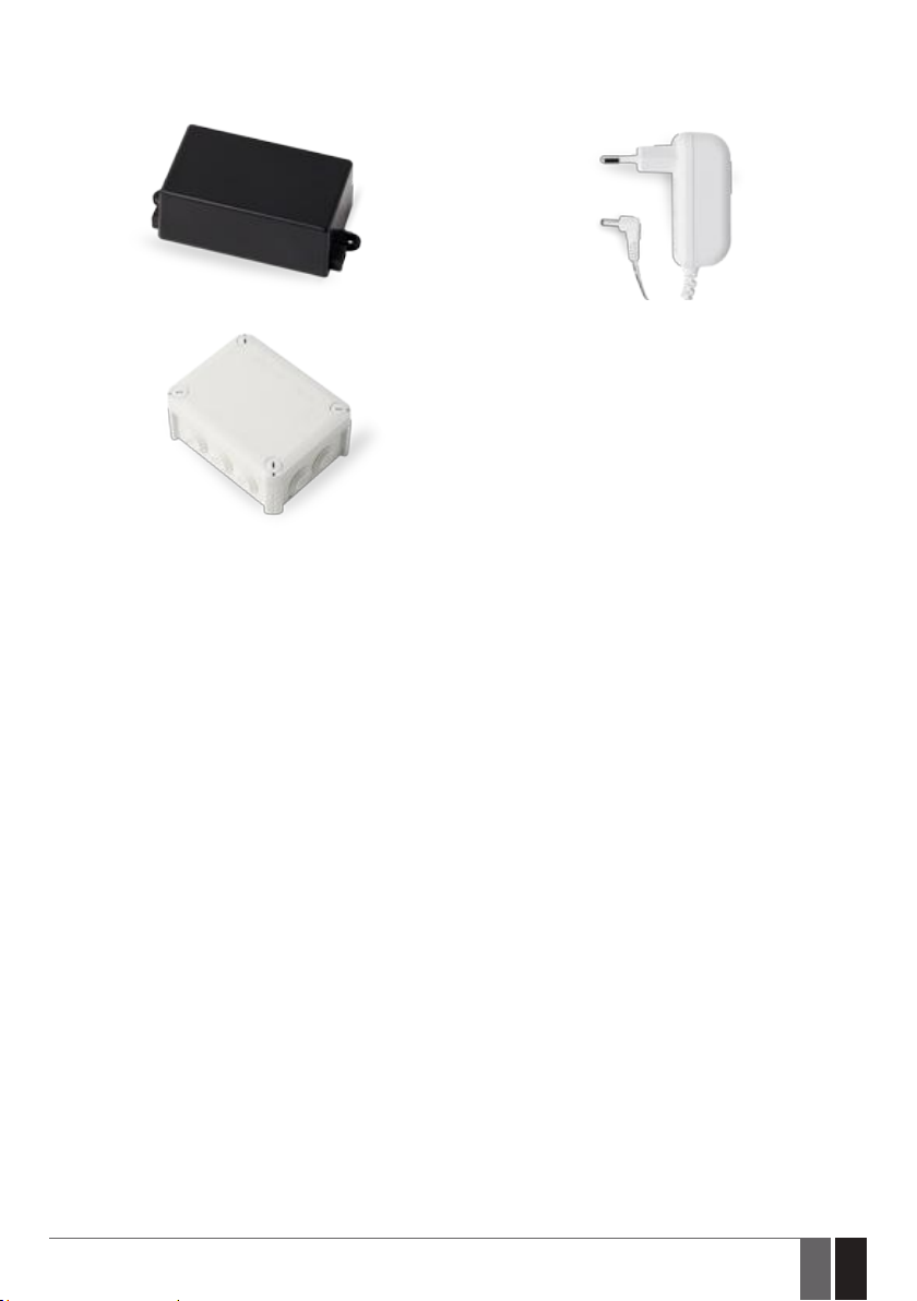
22. RELATED PRODUCTS
EBU1 – power backup unit
IP66 - plastic enclosure
Power supply
ELDES GATE CONTROLLER ESIM120/320 User Manual v.1.1
33
33EN
Page 34

Made in the European Union
eldesalarms.com
 Loading...