

Page 1
11/2010 - Art. Nr. 4200 1029 8600A
VL 2.120 D
VL 2.160 D
VL 2.210 D
Operating instructions
For specialist installation engineers
Fuel oil burners......................................2-25
en
de, fr..................................... 4200 1029 8400
it, nl ......................................4200 1029 8500
............................................. 4200 1029 8300
Page 2

11/2010 - Art. Nr. 4200 1029 8600A2
Overview
Contents
Overview Contents.................................................................... 2
Important information ................................................ 2
Burner description..................................................... 3
Operation Operating mode, safety function............................... 4
Automatic combustion control unit.........................5-7
Terminal allocation chart, connection
socket.....................................................................8-9
Fuel oil burner pump ............................................... 10
Assembly Installing the burner, burner installation location.....11
Electrical connection, fuel oil connection ............... 12
Commissioning Checks before commissioning ................................ 13
Setting data, checking combustion
components ............................................................ 13
Air regulation, fuel oil pressure regulation............... 14
Adjusting burner output......................................15-20
Maintenance Servicing ............................................................ 21-22
Troubleshooting ...................................................... 23
Fault diagnosis menu.............................................. 24
Operating statistics menu .................................. 24-25
We accept no responsibility for
damage arising from:
- inappropriate use.
- incorrect installation and/or repair on
the part of the buyer or any third party,
including the fitting of non-original
parts.
Final delivery and instructions for
use
The firing system fitter must supply the
operator of the system with operating
and maintenance instructions on or
before final delivery. These instructions
should be displayed in a prominent
location at the point of installation of the
heat generator, They should include the
address and telephone number of the
nearest customer service centre.
Notes for the operator
The system should be inspected by a
specialist at least once a year.
Depending on the type of installation,
shorter maintenance intervals may be
necessary! It is advisable to take out a
maintenance contract to guarantee
regular servicing.
Important information
The VL 2.120 D, VL 2.160 D and
VL 2.210 D burners are designed to
burn extra light fuel oil in accordance
with national standards:
AT: ÖNORM C1109: standard or low
sulphur
BE: NBN T52.716: standard or NBN
EN590: low sulphur
CH: SN 181160-2: extra-light fuel oil
and low sulphur eco fuel oil
DE: DIN 51603-1: standard and low
sulphur.
The design and function of the burners
meet standard EN 267.
Installation, commissioning and
maintenance must only be carried out by
authorised specialists and all applicable
directives and regulations must be
complied with.
Burner description
The VL 2.120 D, VL 2.160 D and
VL 2.210 D burners are two-stage fully
automatic monoblock devices. They are
suitable for use with all heat generators
complying with standard EN 303 or for
use by hot air generators complying with
DIN 4794 or DIN 30697 within their
respective performance range. Any
other type of application requires the
approval of ELCO.
Packaging
The burner is supplied packaged in two
boxes on a pallet:
- Burner housing with operating
instructions, wiring diagram.
- Burner head with flange seal and
securing screws.
The following standards should be
observed in order to ensure safe,
environmentally sound and energyefficient operation:
EN 226
Connection of fuel oil and forceddraught gas burners to a heat generator
EN 60335-1, -102
Safety of electrical equipment for
domestic use
Installation location
The burner must not be used in rooms
with aggressive vapours (e.g. hair spray,
tetrachloroethylene, carbon
tetrachloride), high levels of dust or high
air humidity (e.g. laundry rooms).
If no connection to an air exhaust
system is provided for the air supply,
there must be a supply air inlet
measuring:
DE: up to 50 kW: 150 cm
2
per additional kW: : + 2.0 cm
2
CH: QF [kW] x 6= ...cm2; but at least
150 cm
2
.
Variations may arise as a result of local
regulations.
Declaration of conformity
for fuel oil burners
We, certified company No.AQF030,
F-74106 ANNEMASSE Cedex, declare
under our sole responsibility that the
products
VL 2.120 D
VL 2.160 D
VL 2.210 D
conform to the following standards
EN 50165
EN 55014
EN 60335-1
EN 60335-2-102
EN 60555-2
EN 60555-3
EN 267
Belgian royal decree dated 08/01/2004
These products bear the CE mark in
accordance with the stipulations of the
following European Directives
2006/ 42/EC Machinery directive
2004/108/EC EMC directive
2006/ 95/EC Low voltage directive
92/ 42/EEC EEC Working
efficiency directive
Annemasse, 26th March 2010
M. SPONZA
Page 3
11/2010 - Art. Nr. 4200 1029 8600A 3
Overview
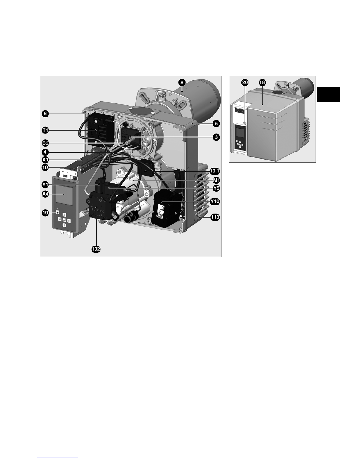
Burner description
Y10 Air flap servomotor
A1 Automatic combustion control unit
A4 Display
B3 Flame monitor
M1 Blower and pump motor
T1 Igniter
3 Adjusting screw for dimension Y
4 Nozzle line tube
5 Housing
6 Plate hanging device
8 Burner tube
10 7-pin connector (hidden)
10.1 4-pin connector
18 Cover
19 Release knob
20 Hood securing screw
102 Fuel oil pump
Y1,Y5Solenoid valves
113 Air intake box
en
Page 4
11/2010 - Art. Nr. 4200 1029 8600A4
Operation
Operation
Safety function
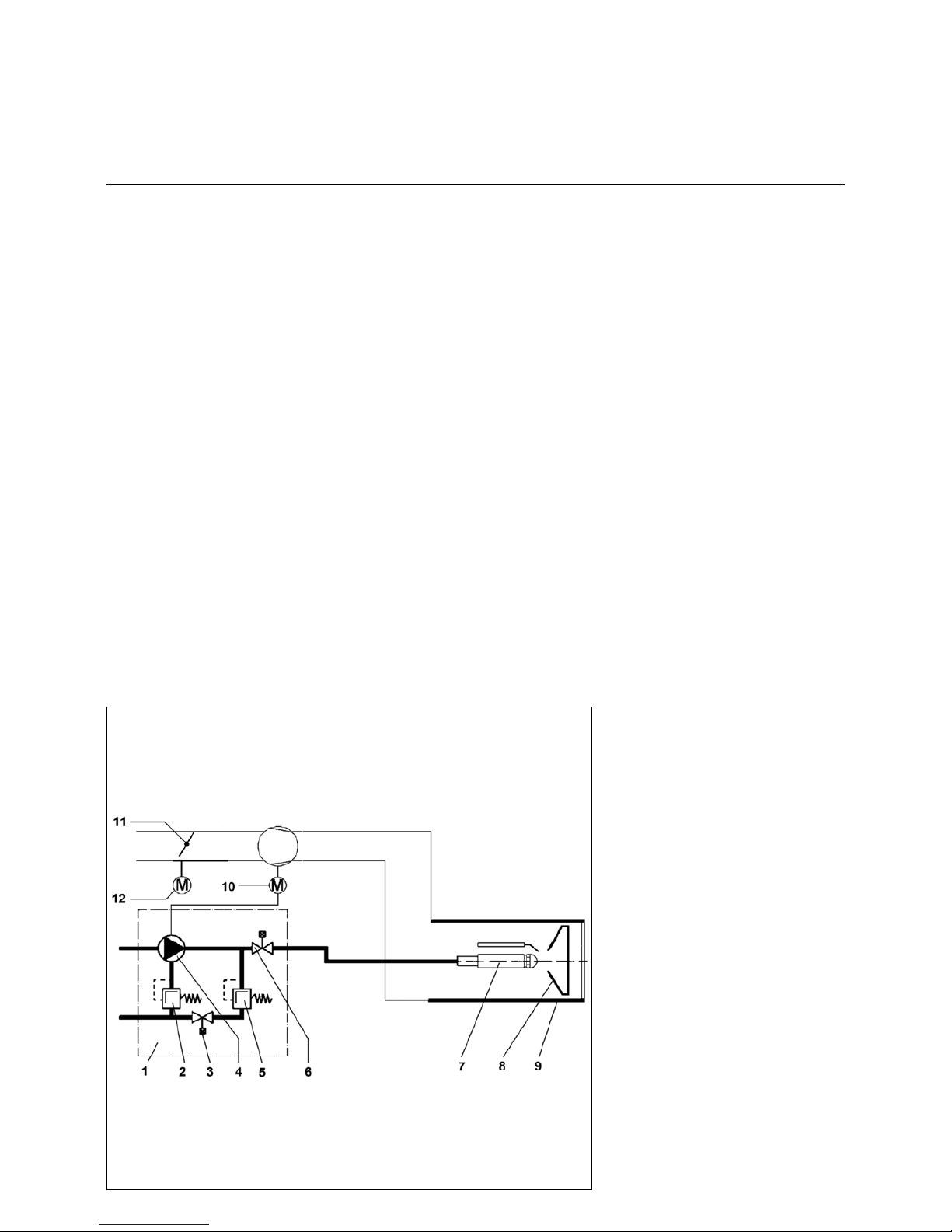
Principle diagram
1 two-stage pump.
2 Oil pressure regulator, full load
3 Solenoid valve, full load (NO)
4Pump
5 Oil pressure regulator, partial load
6 Solenoid valve (NC)
7 Nozzle line
8 Baffle plate
9 Flame tube
10 Burner motor
11 Air flap
12 Air flap electric servomotor
Starting the burner
- After heat is requested by the boiler
regulator, the automatic combustion
control unit starts the program
sequence.
- The blower motor starts up, the ignition
switches on.
- Pre-ventilation with air flap open (air
flap is only closed when the burner is
switched off).
- The solenoid valve 6 opens, pressure
set by the partial load regulator 5.
- Flame formation.
- Ignition switches off.
Burner operation, regulation between
partial load and full load
The burner operates with one nozzle
and at two different fuel oil pressures,
one for partial load and one for full load.
The oil pressures are controlled
independently by two pressure
regulators in the pump.
If an increase in load is requested by the
boiler regulator, the burner switches
from partial load to full load after a delay
of at least 13 seconds.
- Air flap 11 is moved to the full load
position by the servomotor.
- When the air flap position is
adjustable, the solenoid valve 3
closes, the part-load pressure
regulator 5 is deactivated and the full
load pressure regulator 2 takes over
regulation of the pressure.
- The air flap continues to move to the
full load position. The full load is in
operation.
Safety function
A safety shutdown is triggered:
- if a flame signal is detected during preventilation (unauthorised flame
monitoring),
- if no flame is produced within 5
seconds (safety time) of the burner
being started (fuel inlet authorisation),
- if no flame is produced after an
unsuccessful restart attempt in the
event of flame failure during
operation.
A safety shutdown is indicated by the
malfunction lamp lighting up. Once the
cause of the malfunction has been
rectified, it is possible to unlock the
control unit by pressing the reset button.
Page 5
11/2010 - Art. Nr. 4200 1029 8600A 5
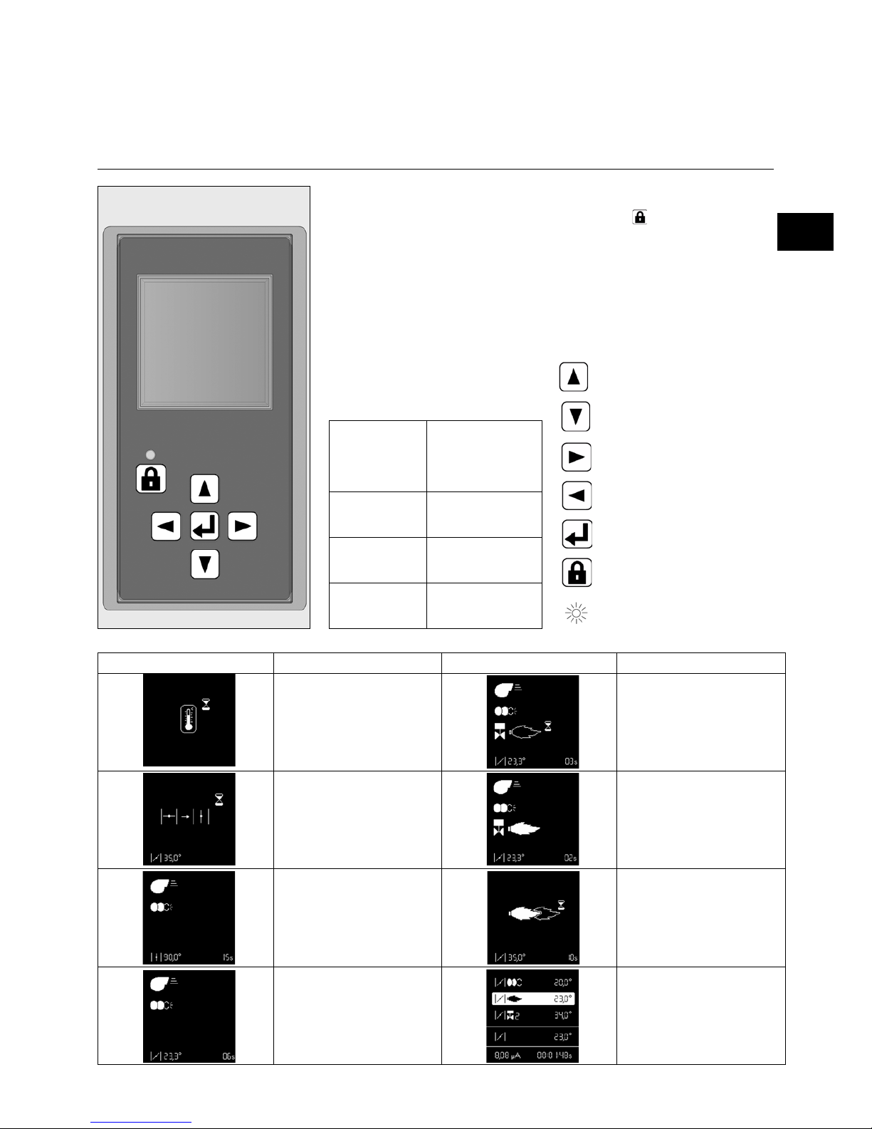
Locking and unlocking
The control unit can be locked using the
release knob or unlocked as long as
the unit is powered on.
Always switch off the power supply
before installing or removing the
control unit. Do not attempt to
open or carry out repairs on the
control unit.
Operation
TCH 2xx safety unit
Moves the cursor upwards.
Moves the cursor downwards.
Increases the marked value.
Modifies/Confirms the value
shown.
Modifies/Confirms the value
shown.
Unlocks the control unit.
Red LED (flashes if a fault is
present).
The TCH 2xx fuel oil automatic
combustion control unit controls and
monitors the forced draught burner. The
microprocessor-controlled program
sequence ensures maximum stability of
time periods, regardless of fluctuations
in the power supply voltage or the
ambient temperature. The automatic
combustion control unit is designed to
cope with brownouts. Whenever the
supply voltage drops below its rated
minimum level (< 185V), the control unit
shuts down - even in the absence of a
malfunction signal. The control unit
switches itself back on again once the
voltage has returned to normal levels
(> 195V).
Pressing and
holding the
unlocking button
for...
… causes …
... 1 second ... the control unit to
unlock.
... 2 seconds ... the control unit to
lock.
... 9 seconds ... the statistics to be
deleted
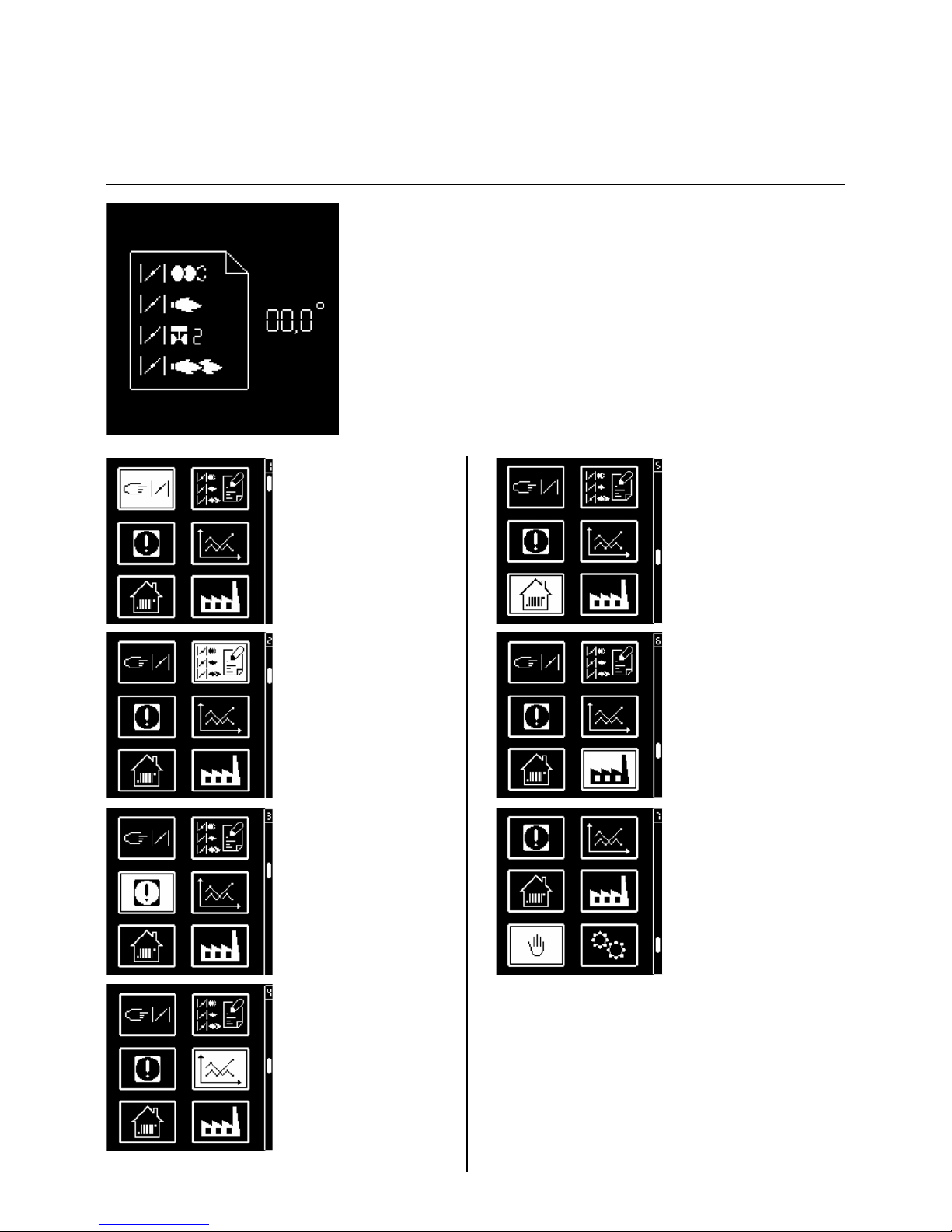
Screen Description Screen Description
Awaiting the heat request from
the boiler
Oil valve is opened, safety time
Air flap is forced open for pre-
ventilation.
Flame stabilises, post-ignition
time
Pre-ventilation and pre-ignition
Flame is present, awaiting
authorisation of regulation
Air flap closes to the ignition
position
Burner in operation. The lower
cell shows the strength of the
signal and the operating time of
the burner.
en
Page 6
11/2010 - Art. Nr. 4200 1029 8600A6
In parallel with its control and safety
functions, the TCH2xx control unit
allows the following to be set:
- the position of the air flap during
ignition
- the position of the air flap during the
1st stage
- the position of the air flap by opening
the stage 2 valve (for switching from
1st to 2nd stage)
- the position of the air flap during the
2nd stage
- the position of the air flap by closing
the stage 2 valve (for switching from
2nd to 1st stage).
The parameters for the control unit are
set using the display and 5 keys.
Operating values are shown in real time
on the display.
Pressing the keys gives access to 7
menus:
(The last two menus are not activated for
VL 2 D burners)
Operation
TCH 2xx safety unit
• menu for setting the
servomotor,
• menu for storing the
servomotor setpoints in
the display
• fault diagnosis menu
• operating statistics
menu
• menu for setting/
adjusting the standard
configurations.
• menu for setting
industrial applications
• menu for manual control
In these menus, it is
possible to adjust the
control unit's standard
configurations. These are
pre-set in the factory. No
modifications may be
carried out on-site without
prior consultation with
ELCO. The access code
and the setting setpoints
for this menu are available
on request.
Page 7
11/2010 - Art. Nr. 4200 1029 8600A 7
Operation
TCH 2xx safety unit
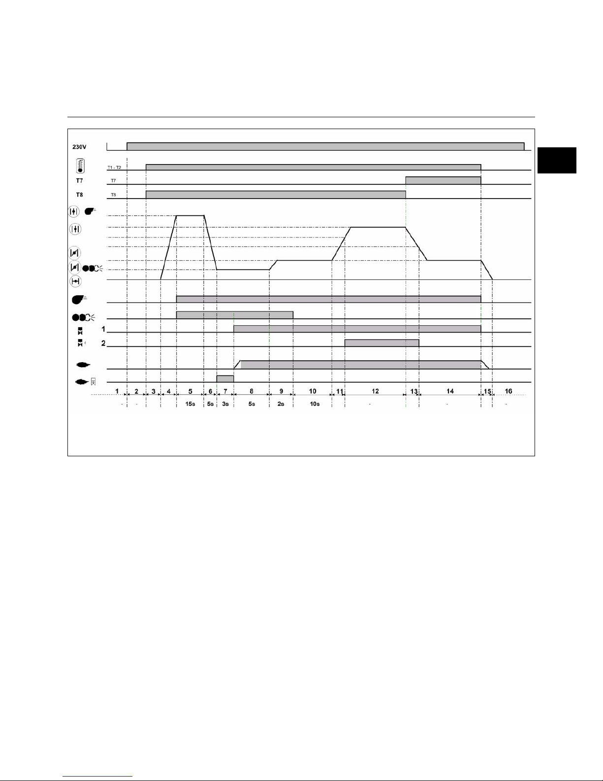
Operating cycle phases:
1: No voltage
2: Powering up, no heat request
3: Heating request
4: Air flap opens to the preventilation
position
5: Pre-ventilation: Switching on the
motor and the igniter
6: Closing the air flap, switching to
the ignition position
7: Unauthorised flame monitoring
8: Starting the burner: opening the
solenoid valve, flame formation,
safety time
9: Flame stabilisation time, post-
ignition time
10: Awaiting regulator release
11: Opening the air flap, until the
opening position of the 2
nd
stage
valve is reached
12: Operation in 2
nd
stage
13: Closing the air flap, until the
closing of the 2
nd
stage valve
14: Operation in 1
st
stage
15: Regulator shutdown, closure of
the air flap to 0°
16: Awaiting a new heating request
en
Page 8
11/2010 - Art. Nr. 4200 1029 8600A8
Earth
Pre-heater
Flame monitor
Fault
display
Air
pressure
switch
Igni tionBurner motor
2nd stage
solenoid valve
Connector
Terminal
Terminal
Connector
Remote
unlocking
L1 power
supply
1st stage
solenoid valve
3rd stage
solenoid valve
2nd stage
thermostat
Heating
request
Earth
Fuel pump
pump unit
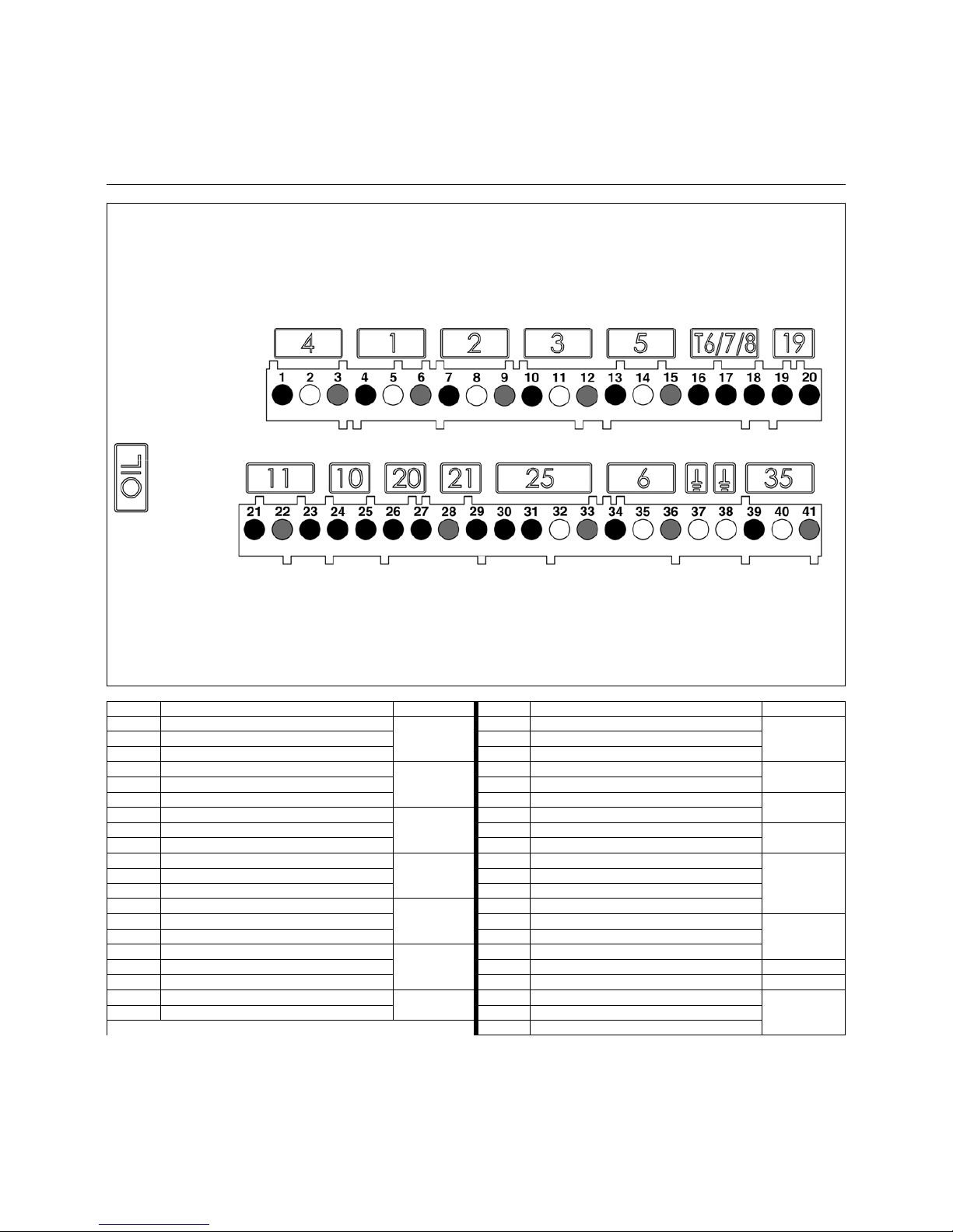
Terminal Description Connector Terminal Description Connector
1 Burner motor live
4
21 Flame monitoring signal
11
2 Earth 22 Neutral
3 Neutral 23 Live
41
st
stage solenoid valve live
1
24 Not used
10
5 Earth 25 Not used
6 Neutral 26 Live
20
72nd stage solenoid valve live
2
27 Remote unlocking signal
8 Earth 28 Neutral
21
9 Neutral 29 Signal fault live
10 3
rd
stage solenoid valve live
3
30 Live
25
11 Earth 31 Preheater/release contact
12 Neutral 32 Earth
13 Igniter live
5
33 Neutral
14 Earth 34 Live L1
6
15 Neutral 35 Earth
16 2
nd
stage thermostat phase (T6)
T6/7/8
36 Neutral
17 Signal T7 37 Earth
18 Signal T8 38 Earth
19 1
st
stage thermostat live (T1)
19
39 Pump unit live
35
20 Heating request signal (option T2) 40 Earth
41 Neutral
Operation
Terminal allocation chart
230 Volt connection
Page 9
11/2010 - Art. Nr. 4200 1029 8600A 9
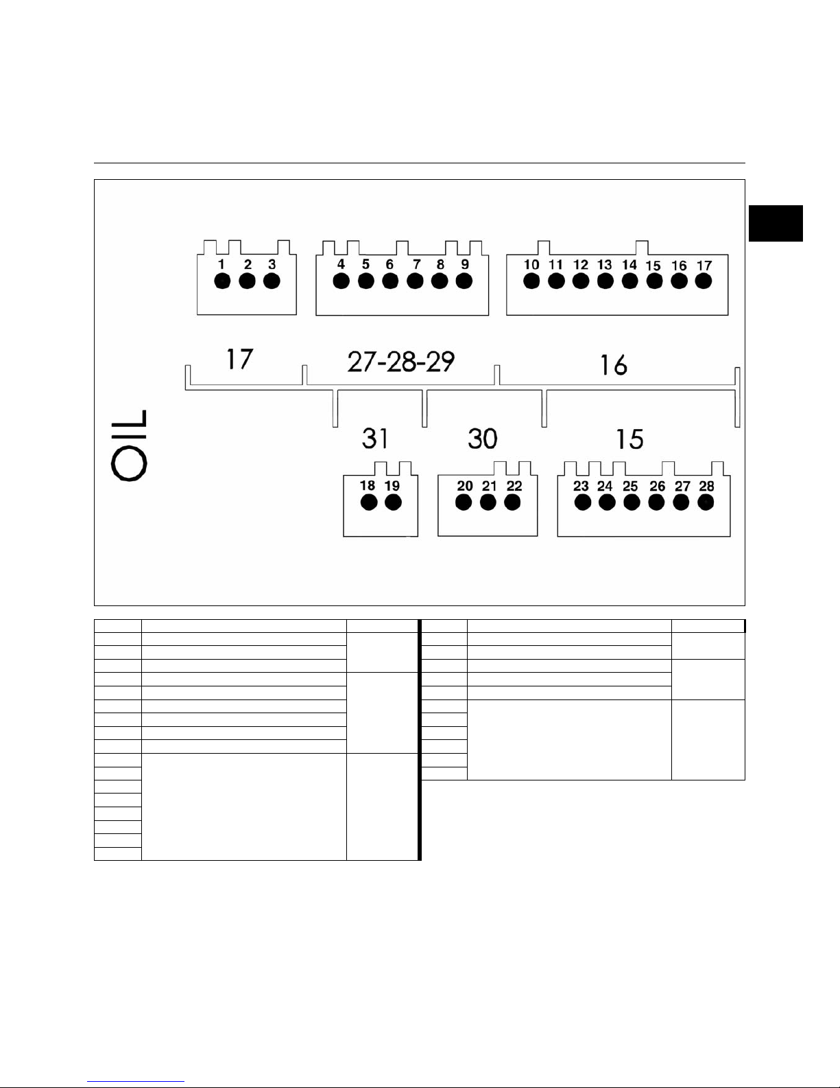
Display-PC interface
Air flap servomotor
Connector
Terminal
Terminal
Connector
Terminal Description Connector Terminal Description Connector
1 Not used
17
18 Not used
31
2 Not used 19 Not used
3 Not used 20 Not used
30
4 Not used
27
28
29
21 Not used
5 Not used 22 Not used
6 Not used 23
Air flap servomotor
15
7 Not used 24
8 Not used 25
9 Not used 26
10
Display-PC interface
16
27
11 28
12
13
14
15
16
17
Operation
Terminal allocation chart
Low voltage connections
en
Page 10

11/2010 - Art. Nr. 4200 1029 8600A10
Operation
Pump
The pump is a gear pump. It must be
connected as a two-line pump via a
bleed filter. For the connection of the fuel
oil tank and the bleed filter, it is better to
use the single line option. An intake filter
and two oil pressure regulators are
integrated in the pump. Pressure
gauges for pressure measurements 4
and negative pressure measurements 5
must be connected before the
equipment is commissioned.
1 Return connection G 1/4
2 Vacuum connection G 1/4
3 Nozzle supply line
connection G1/8
4 Pressure gauge connection
5 Vacuum gauge connection
8 Pressure setting, 1st stage
9 Pressure setting, 2nd stage
Y1 Solenoid valve, 1st stage
Y5 Solenoid valve, 2nd stage
Page 11

11/2010 - Art. Nr. 4200 1029 8600A 11
Assembly
Burner assembly
Burner tube installation depth and
brickwork surround
Unless otherwise specified by the boiler
manufacturer, heat generators without a
cooled front wall require brickwork or
insulation 5 as shown in the illustration
opposite. The brickwork must not
protrude beyond the leading edge of the
flame tube, and should have a maximum
conical angle of 60°. Space 6 must be
filled with an elastic, non-flammable
insulation material.
On boilers with reverse firing, minimum
flame tube insertion depth A should be
observed as per the boiler
manufacturer's instructions.
en
For assembly in the position with
the volute facing upwards, unclip
the display from its support, turn it
over 180°, and refit it.
Exhaust gas evacuation system
To avoid unpleasant noise emissions,
right-angled connectors should not be
used on the flue gas side of the boiler.
Inspection glass cooling
The burner housing can be equipped
with an R1/8" connection to support a
line for cooling the inspection glass of
the boiler.
• To do this, drill through boss 6 and cut
an 1/8" thread.
Use accessories article No.
12 056 459 for the connecting nipple and
connection hose.
Burner assembly
Burner flange 3 is equipped with
elongated holes and can be used with a
hole circle diameter of 150 - 184mm.
These dimensions comply with EN 226.
Sliding pipe bracket 2 on the burner pipe
makes it possible to adjust the installed
depth of the mixing unit to the geometry
of the combustion chamber concerned.
The installed depth remains the same
during fitting and removal.
Pipe bracket 2 secures the burner to the
connecting flange and therefore to the
boiler. This completely seals off the
combustion chamber.
Installation:
• Secure connecting flange 3 to the
boiler using screws 4
• Fit pipe bracket 2 to the burner pipe
and secure using screw 1. Tighten
screw 1 to a maximum torque of 6 Nm.
• Turn the burner slightly, guide it into
the flange and secure using screw 5.
Removal:
• Loosen screw 5
• Turn the burner out of the bayonet
socket and pull it out of the flange.
Page 12

11/2010 - Art. Nr. 4200 1029 8600A12
Fuel oil connection
The fuel oil connection must be done via
a bleed filter. The filter must be
positioned in such a way as to ensure
the hoses are routed correctly. The
hoses must not be pinched. The fuel oil
pipes used must be in DN6 or DN8
copper pipe.
CH: Fuel oil pipe in
DIN 16773 polyamide.
For the maximum values of the suction
lengths and heights, see the directive for
carrying out and sizing installations with
suction.
This directive forms an integral part of
the elements ELCO planning is based
on. The suction strainer must not be less
than 5cm from the bottom of a square
tank and not less than 10cm from the
bottom of a cylindrical tank.
Assembly
Electrical connection
Fuel oil connection
Fuel oil connection
To ensure the operating safety of the
system, the fuel oil supply must be
installed carefully in compliance with
local regulations.
Important:
• Maximum pressure at the pump intake
< 1.5 bar.
• Maximum vacuum pressure at the
pump < 0.4 bar.
• Before commissioning, fill the oil lines
and check there are no leaks.
Electrical installation and connection
work must only be carried out by a
suitably qualified electrician. All
applicable regulations and directives
must be observed.
Electrical connection
• Check to ensure that the power supply
is as specified (230V, 50 Hz single
phase with neutral and earth)
Boiler fuse: 10 A
Electrical connection
It must be possible to disconnect
the burner from the mains using an
omnipolar shutdown device
complying with the standards in
force. The burner and heat
generator (boiler) are connected
by a 7-pin Wieland connector 1
and a 4-pin Wieland connector 2
(not supplied). The diameter of
the cables connected to these
connectors must be between 8.3
and 11 mm.
Page 13

11/2010 - Art. Nr. 4200 1029 8600A 13
Commissioning
Checks before commissioning
Adjustment data
Checking combustion components
Checks before commissioning
The following must be checked before
initial commissioning:
• That the burner is assembled in
accordance with the instructions given
here.
• That the burner is pre-set in
accordance with the values in the
adjustment table.
• Setting the combustion components.
• The heat generator must be ready for
operation, and the operating
regulations for the heat generator
must be observed.
• All electrical connections must be
correct.
• The heat generator and heating
system must be filled with water and
the circulating pumps must be in
operation.
• The temperature regulator, pressure
regulator, low water detectors and any
other safety or limiting devices that
might be fitted must be connected and
operational.
• The exhaust gas duct must be
unobstructed and the secondary air
system, if available, must be
operational.
• An adequate supply of fresh air must
be guaranteed.
• The heat request must be available.
• Fuel storage tanks must be full.
• The fuel supply lines must be
assembled correctly, checked for
leaks and bled.
• A standard-compliant measuring point
must be available, the exhaust gas
duct up to the measuring point must
be free of leaks to prevent anomalies
in the measurement results.
The settings data below are basic
settings. The factory settings data is
highlighted in bold and with a grey
background. With a normal case, these
settings enable the commissioning of
the burner. In all cases, carefully check
the settings values. In most cases,
according to the installation, corrections
must be made.
Checking checking combustion
components
• Disconnect the ignition cable on the
transformer side.
• Loosen the nozzle supply line.
• Loosen the three cover screws W.
• Remove the cover and remove the
mixture ignition device.
• Check nozzle sizes and exchange in
accordance with the parts specified in
the above table if necessary.
• Check the adjustment of the ignition
electrodes block and the baffle plate
and adjust if necessary.
• Check the gap between nozzle and
baffle plate and adjust if necessary.
en
1. stage 2. st age 1. stage 2. stage 1. st age 2. sta ge
60 80 5 7 1,35 11 22 20 30 30 40 50
70 100 6 8 1,50 11 22 30 30 30 40 60
90 120 8 10 2,00 11 22 35 35 35 40 60
80 110 7 9 1,75 11 21 25 30 30 40 50
100 140 8 12 2,25 11 2 2 30 3 5 35 40 90
110 160 9 13 2,50 11 2 2 35 3 5 35 40 90
100 140 8 12 2,25 11 2 2 15 3 5 35 40 70
125 170 11 14 2 , 75 11 22 20 40 40 65 90
150 210 13 18 3 , 00 11 21 35 50 50 65 90
Burner
2. stage
Stage
changeover
Ignition
Burner power
kW
Bold : Delivery setting; 1kg fuel-oil at 10°C = 11.86kWh
VL 2.120 D
VL 2.210 D
Fuel-oil flow
kg/h
Pump pressure
bar
Dimens io n
Y
mm
Nozzle
45°S
Gph
(D a nfoss)
A ir flap position
in °
VL 2.160 D
1. stage
BCDE
VL 2.120/160 D 4811
VL 2.210 D 5553
Combustion head settings
Head setting values (space between
nozzle and turbulator - dimension B,
space between nozzle and ignition
electrodes - dimension C) can be
checked with enclosed drawing. The two
dimensions are set in the factory.
Dimension B was set thanks to adjust
ring 5. While reassembling the turbulator
for a nozzle replacement, it is not
necessary to re-adjust dimension B, as
far as the turbulator is re-assembled on
the stop on ring 5.
Page 14

11/2010 - Art. Nr. 4200 1029 8600A14
Commissioning
Air regulation
Fuel oil pressure regulation
Air regulation
Combustion air is regulated at two
points:
• on the pressure side, by the gap
between the baffle plate and the
burner tube.
• on the vacuum side, by the air flap
driven by servomotor Y10.
The regulation of air in the burner head
affects not only the air flow but also the
mixing zone and the air pressure in the
burner tube. Rotation of setting screw A
- right: more air
- left: less air
• Adjust dimension Y in accordance with
the settings table.
Air regulation by air flap
Air is regulated on the vacuum side by
an air flap. This is driven by servomotor
Y10.
Fuel oil pressure regulation
The fuel oil pressure is adjusted using
fuel oil pressure regulator 8 for the 1st
stage and fuel oil pressure regulator 9
for the 2nd stage. To check the
pressure, connect a R1/8" pressure
gauge to connector 4.
Turn
- right: to increase the pressure
- left: to reduce the pressure
Checking the vacuum pressure
The vacuum meter for checking
negative pressure must be connected to
point 5, R1/8". Maximum authorised
vacuum: 0.4 bar. At higher vacuum
pressures, the fuel oil gasifies, which
causes scraping noises in the pump and
risks damaging it.
1 Return connection G 1/4
2 Vacuum connection G 1/4
3 Nozzle supply line
connection G1/8
4 Pressure gauge connection
5 Vacuum gauge connection
8 Pressure setting, 1st stage
9 Pressure setting, 2nd stage
Y1 Solenoid valve, 1st stage
Y5 Solenoid valve, 2nd stage
Page 15

11/2010 - Art. Nr. 4200 1029 8600A 15
Modifying a settings value for the servomotor position:
- To modify the value of a position, move the cursor to the
corresponding location with the button or .
- Select the value to be modified using the button , the
selected value will flash.
- Increase or decrease the value in increments of 0.1° by
repeatedly pressing or . For large modifications, press
and hold the or button, the value will scroll quickly up
or down.
- Confirm the new value using the button . The value stops
flashing.
N.B.:
It is possible to set different positions within a large range of
values. However, for safety reasons, the control unit enforces
a minimum interval of 2° between the different positions
(except between the ignition position and the 1st stage).
• Press any button and the
following screen will appear:
The overall view of the menus
is displayed, and the air flap
positions settings menu is
selected.
• Open the settings menu by
pressing the button .
You must now enter the
access code (see the label on
the back of the display)
• Increase or decrease the
value in increments by
repeatedly pressing or
.
• When the first figure has
been set, move the cursor to
the right by pressing .
• Repeat the operation until
you reach the last figure.
• Confirm the access code by
pressing .
The control unit then opens
the settings mode. The screen
displays the factory presettings for the different
positions of the air flap (here
for example: for a VL 2.210 D).
The following positions for the
air flap are presented:
- ignition position (when the
menu is opened, the curser
goes to this position)
- position of the air flap during
the 1st stage
- position of the air flap when
the 2nd stage fuel oil valve is
opened
- position of the air flap during
the 2nd stage
Commissioning
Pre-setting without flame
Setting is carried out in 2 phases:
- pre-adjustment without flame
- setting the flame, to fine tune the
settings based on the combustion
results
When the burner is switched on, the
control unit displays the screen below.
Important
At this point, no setting position for the
servomotor has been defined, therefore
the burner cannot be started under
these conditions.
en
Page 16

11/2010 - Art. Nr. 4200 1029 8600A16
End of settings menu without flame
When all the positions of the servomotor have been determined according to the required
settings, it is then possible to move on to the next section for commissioning - "Setting the flame".
To do this, place the cursor in the lower part of the screen on the symbol and confirm by
pressing the button .
If it is necessary to quit the menu without saving the pre-settings, position the cursor on the
symbol and confirm with the button .
Commissioning
Pre-setting without flame
General advice before starting the burner
Preparing the burner start-up
Before starting the burner, draw fuel oil
in using a hand pump until the filter is
completely filled. Then start the burner
by switching on the boiler regulator.
Open the bleed screw on the oil filter to
allow the oil line to bleed fully during the
pre-ventilation phase. The negative
pressure must not fall below 0.4 bar.
Close the bleed screw when the filter is
completely filled with fuel oil and fuel oil
is flowing out without bubbles.
Optimising combustion values
Optimum combustion values can be
achieved by adjusting the position of the
baffle plate (dimension Y) if necessary.
Doing this can have an effect on starting
characteristics, pulsation and
combustion values. Any reduction in
dimension Y increases the CO
2
value.
However, starting characteristics
become harsher.
Compensate for the change in airflow if
necessary by adjusting the air flap
position.
Precautions: To avoid condensation,
observe the minimum required flue
gas temperature specified by the
boiler manufacturer and comply with
the requirements for flue gas ducts.
If dimension Y needs to be corrected
again when the 2
nd
stage is adjusted, it
will be necessary to check the
adjustment values for the 1
st
stage.
Risk of air blast!
Continuously check CO, CO
2
and
soot emissions when adjusting.
Optimise combustion values if CO is
present. The CO level must not
exceed 50 ppm.
Function check
Flame monitoring must be checked for
safety as part of initial commissioning
and also after servicing or if the system
has been out of operation for any
significant period of time.
- Start attempt with the flame detection
cell obscured:
at the end of the safety time,
the control unit must switch to
malfunction mode!
- Start-up with the flame detection cell lit
up: the automatic combustion control
unit must switch to malfunction mode
after 10 seconds of pre-ventilation.
- Normal start; if the burner is in
operation, cover the flame detection
cell: the automatic combustion control
unit must switch to malfunction mode
after a restart and the end of the safety
time
Page 17

11/2010 - Art. Nr. 4200 1029 8600A 17
- If the boiler heating
request is not present, the
boiler remains on standby.
In this case, it is still possible
to return to the previous
setting menu "Pre-setting
without flame". To do this,
position the cursor on the
symbol and confirm with
the button .
- If a boiler heating request
is present (T1-T2 contact
closed), the burner starts.
The air flap is opened to move
to the pre-ventilation position.
Pre-ventilation and preignition
The air flap switches to the
ignition position.
The fuel valve opens.
Awaiting flame signal
If no flame is detected at the
end of the safety time, the
control unit switches to
malfunction mode.
Flame detected
Flame stabilisation
The control unit awaits the
regulation authorisation.
Commissioning
Setting the flame
en
Page 18

11/2010 - Art. Nr. 4200 1029 8600A18
Setting the 1st stage
If the flame has been detected and stabilised, the control unit sets the burner to the 1st stage as
soon as it receives the regulation authorisation.
- Adjust the fuel oil pressure for the 1st stage depending on the required output, using the
regulator 8 on the pump. Monitor the combustion values continuously as you do so (CO, CO
2
,
soot test). If necessary, adjust the dimension Y and/or adapt the airflow.
To do this, modify the position of the servomotor in 1st stage. Proceed as described on page 15,
in the paragraph "Modifying the value of a servomotor position setting"
- Precautions: when modifying the setting value, the servomotor will move in real time. As a
consequence, the combustion values must be constantly checked.
Specific function: ignition checking
If the ignition position has been modified, it is possible to carry out a new burner start-up to check
the new ignition position, without having to quit the settings menu.
To do this, after modifying the ignition position, position the cursor on the symbol , and initiate
the new start-up using the button .
Setting the opening position of the 2nd stage fuel oil valve
After the 1st stage is set, it is possible to set the opening value for the 2nd stage fuel oil valve.
Proceed as described in the paragraph "Modifying the value of a servomotor position
setting"
- Precautions: in this case the servomotor does not move immediately, but first remains in the 1st
stage position (the actual position of the servomotor is always displayed in the lower part of the
display). The 2nd stage valve also remains closed. Firstly it is possible to modify the position of
the 2nd stage air flap.
Setting the 2nd stage
To set the position of the air flap in the 2nd stage, position the cursor on the corresponding line
on the display using the button . If necessary, modify the setting value. Proceed as described
in the paragraph "Modifying the value of a servomotor position setting".
- To make the burner actually switch to the 2nd stage, press the button again. The servomotor
will then move the air flap to the set position. At the same time, the 2nd stage fuel oil valve will
open, as soon as the opening position set for the servomotor is passed.
- Adjust the fuel oil pressure for the 2nd stage depending on the required output, using the
regulator 9 on the pump. Monitor the combustion values continuously as you do so (CO, CO
2
,
soot test). If necessary, adjust the dimension Y and/or adapt the airflow.
To do this, modify the position of the servomotor in the 2nd stage. Proceed as described on page
15, in the paragraph "Modifying the value of a servomotor position setting"
- Precautions: when modifying the setting value, the servomotor will move in real time. As a
consequence, the combustion values must be constantly checked.
Specific function: position the opening and closing of the 2nd stage fuel oil valve
differently
The control unit has the possibility of setting the opening of the 2nd stage valve, when the 1st
stage changes to the 2nd stage, at a different position to that for closing when the 2nd stage drops
to the 1st stage.
- To do this, as described before, first set the opening position of the 2nd stage fuel oil valve.
- Lastly position the cursor on the symbol and confirm with the button . The selected symbol
will change like this one .
- Using the button , position the cursor on the setting value of the 2nd stage fuel oil valve, and
fix the new closure position, as described in the paragraph "Modifying the value of a
servomotor position setting".
Commissioning
Setting the flame
Page 19

11/2010 - Art. Nr. 4200 1029 8600A 19
Closing the "Setting the flame" menu
The burner setting is now complete. If necessary, it is possible to again correct each of the
settings values. To do this, position the cursor on the value to be modified, using the button
or .
Otherwise, at all times, the following possible ways of closing the "Setting the flame" menu are
available:
- Returning to the burner settings with passing through the pre-setting phase (without entering a
password). To do this, position the cursor on the symbol and confirm with the button . All
the settings values already saved therefore remain available.
- Saving the fixed values and ending the setting procedure. To do this, position the cursor on the
symbol and confirm with the button . The burner is then ready to operate and can now
be controlled by the boiler regulation.
- Quitting the settings menu without reaching the end of the setting procedure. To do this, position
the cursor on the symbol and confirm with the button . All the servomotor positions saved
up to this point are recovered by calling up the settings menu again.
Commissioning
Setting the flame
Operating mode
Operating mode - Display of the operating status, the flame signal and the operating time
After having completed the setting of the burner, it switches to operating mode.
The current operation of the burner (Operation in 1st or 2nd stage) is indicated by the light bar.
The lower cell shows the intensity of the signal. The display range is from 0 µA to 13 µA. A good
quality signal is above 3µA.
The following limit values are valid:
• When checking an unwanted flame: the signal must be < 0.7µA
• During the safety time: the signal must be > 1.3µA
• During operation: the signal must be > 1.1µA
The cell at the bottom right displays the current operating time of the burner.
en
Page 20

11/2010 - Art. Nr. 4200 1029 8600A20
Saving the adjustment values in the display
If the burner setting procedure has been successfully completed,
the servomotor positions for all the operating states will be fixed in
the control unit. It is possible to store a backup copy of the values
in the display.
To do this, press the button , the screen opposite is displayed.
Using the button select the menu "Save adjustment values"
and confirm with the button .
The screen opposite appears. Place the cursor on the symbol ,
press the button to begin loading the adjustment values from
the control unit to the display.
A this point, it is possible to:
- store the values in the display; to do this place the cursor on the
symbol and confirm with button .
- quit the menu without storing the data, with the symbol .
Commissioning
Saving the adjustment values in the display
Page 21

11/2010 - Art. Nr. 4200 1029 8600A 21
Maintenance
Servicing
Work recommended as part of annual
burner maintenance:
- Burner test run, input measurement in
the boiler room
- Clean the combustion components
and replace defective parts if
necessary
- Cleaning the fan wheel and blower and
checking the pump coupling
- Check the nozzle; replace if necessary
- Checking or replacing the fuel oil filters
(pump, feed lines)
- Visual inspection of the fuel oil hoses;
replace if necessary
- Visual inspection of the burner's
electrical components; elimination of
damage if necessary
- Check burner start characteristics
- Checking oil pressure and vacuum at
the burner pump with the burner in
operation
- Flame detector and control unit
function check
- Correct the adjustment values if
necessary
- Draw up a measurement report
General checks
- Emergency stop button function check
- Visual inspection of oil lines in the
boiler room
Fitting the fan wheel
When changing the motor or the fan
wheel, refer to the positioning diagram
opposite. The internal flange A of the fan
wheel must be aligned with plate B.
Insert a ruler between the vanes of the
fan wheel and bring A and B to the same
height. Tighten the cone-point screw on
the fan wheel.
Burner and boiler servicing must only
be carried out by a professional
heating engineer trained in these
operations. The system operator is
advised to take out a maintenance
contract to guarantee regular
servicing. Depending on the type of
installation, shorter maintenance
intervals may be necessary.
• Switch off the power supply before all
maintenance and cleaning work.
• Use original spare parts.
en
Cleaning the fan wheel
• Remove the equipment plate and
attach it in the service position (see
illustration).
• Remove and clean the fan wheel and
replace it if necessary. Reassemble in
the reverse order.
Checking checking combustion
components
• Remove the celle B3.
• Loosen the three cover screws W.
• Remove the mixing unit.
• Check nozzle size and exchange in
accordance with the parts specified in
the table page 13 if necessary.
• Check the adjustment of the ignition
electrodes block and the baffle plate
and adjust if necessary.
• Check the gap between nozzle and
baffle plate and adjust if necessary.
Page 22

11/2010 - Art. Nr. 4200 1029 8600A22
Replacing the flame tube
It is necessary to remove the burner for
this work.
• Loosen the clamping screw on the
connecting flange.
• Turn the burner out of the bayonet
socket, lift it slightly and pull it out of
the connecting flange.
• Place the burner on the floor.
• Loosen the 4 screws X on flame tube.
• Pull the flame tube out towards you.
• Fit and secure the flame tube.
The flame tube may be very hot
Filter replacement
• The filter element of the multiblock
must be checked at least once a year
and replaced if clogged.
• Loosen the screws of the filter cap on
the multiblock.
• Remove the filter element and clean its
housing.
• Do not use any pressurised cleaning
products.
• Replace the filter element with a new
element.
• Screw the cover back into place.
• Reopen the manual shut-off valve.
• Check it is airtight.
• Check the combustion values.
Cleaning the air intake box
• Unscrew securing screws V on the air
intake box.
• Remove and clean the air intake box.
Reassemble in the reverse order.
• Note the correct position of the air flap
and the servomotor.
Cleaning the cover
• Do not use abrasive products or
products containing chlorine.
• Clean the cover with water and a
suitable cleaning product.
• Refit the cover.
Precautions
After any operation: check the
combustion performance under real
operating conditions (doors shut,
cover fitted etc.). Record the results
in the relevant documents.
Checking the flue gas temperature
• Check the flue gas temperature at
regular intervals.
• Clean the boiler if the flue gas
temperature is more than 30 °C above
the value measured at the time of
commissioning.
• Use a flue gas temperature gauge to
make the check easier.
Maintenance
Servicing
Page 23

11/2010 - Art. Nr. 4200 1029 8600A 23
Maintenance
Troubleshooting
Malfunction diagnosis and repair
In the event of a malfunction, first check
that the prerequisites for correct
operation are fulfilled:
1. Is there any current?
2. Is there fuel oil in the tank?
3. Are all shut-off valves open?
4. Are all control and safety devices,
such as the boiler thermostat, lowwater detector, limit switch, etc.
correctly set?
If the cause of the malfunction cannot be
ruled out by the checks described
above, check the functions of the
various burner components.
Important safety components must not
be repaired; these components must be
replaced by parts with the same part
number.
Only use original spare parts.
Switch off the power supply
before carrying out
maintenance or cleaning.
After any operation: check the
combustion performance under real
operating conditions (doors shut,
cover fitted etc.). Record the results
in the relevant documents.
Symbol Observation Cause Corrective action
The thermostat no longer
starts the burner.
No heat requested by
thermostats
Defective control unit.
Check/replace the thermostat.
Replace the control unit.
The burner starts up briefly
when the power supply is
switched on and then stops
The control unit has
intentionally been manually
locked.
Unlock the unit.
The burner starts then stops
after pre-ventilation
Unauthorised flame is
detected during the preventilation/pre-ignition period
Check for the ignition spark/adjust the electrodes/
replace
Check/replace the fuel oil solenoid valve
Checking/replacing the cell
The burner starts and stops
after the solenoid valves have
opened
No flame at the end of the
safety time.
Check fuel oil level in tank.
Top the tank up as required.
Open the valves.
Check the fuel oil pressure and the operation of the
pump, coupling, filter and solenoid valve.
Check the ignition circuit, the electrodes and their
settings. Clean the electrodes.
Clean and replace the cell.
Replace the following parts as required:
ignition electrodes/ignition cables/
igniter/nozzle/pump/solenoid valve/safety unit.
Flame failure during
operation.
The flame goes out during the
operating phase
Servomotor fault Clogging of the air flap
Locking of the air flap
Internal fault with the
servomotor
Replace the servomotor
en
Page 24

11/2010 - Art. Nr. 4200 1029 8600A24
Maintenance
Fault diagnosis menu
Operating statistics menu
Fault diagnosis menu
To access the fault diagnosis menu, press any button when the burner is ready to operate, when
the burner is in operation, or when it is in malfunction mode. It is not possible to access the fault
diagnosis menu during the start-up phase.
The general menu screen will appear. Using the buttons , , , or , place the cursor on
the fault diagnosis menu symbol, and confirm using the button .
The details of the last fault to appear are indicated by the flashing symbol. The flame intensity,
network voltage, air flap position, number of burner start-ups as well as the operating time of the
burner at the time it switched to malfunction mode are displayed underneath.
Using the buttons and , it is possible to call up the details of the last 5 faults to have
appeared (the fault number is displayed in the upper left corner of the display). After the details
of the last 5 faults, the telephone number of the after-sales department as well as the
maintenance contract number are shown (no values are entered in the factory).
• Quit the menu using the button
Entering a telephone number for the maintenance company and the maintenance contract
number
When the corresponding symbol appears on the display:
• Keep the button held down until the first figure starts to flash (a short press will exit the
menu).
• Using the buttons or , change the figure to the value required (underscore = empty field)
• Using the button , move on to the next figure.
• When the number is complete, save using the button .
Operating statistics menu
To access the operating statistics menu, press any button, when the burner is ready to operate,
when the burner is in operation, or when it is in malfunction mode. It is impossible to access the
operating statistics diagnosis menu during the start-up phase.
The general menu screen will appear. Using the buttons , , , or , place the cursor on
the operating statistics menu symbol, and confirm using the button .
The operating statistics menu comprises 7 screens. Navigation between the different screens is
done using the buttons and .
- Flame detection time for last start-up
- Average flame detection time for the latest 5 start-ups
- Total number of burner start-ups
- Total number of faults
- Total number of operating hours
- Total number of operating hours in 2
nd
stage
Page 25

11/2010 - Art. Nr. 4200 1029 8600A 25
- Total number of burner start-ups since the last meter reset
- Total number of faults since the last meter reset
- Total operating time since the last meter reset
- Total operating time in 2nd stage since the last meter reset
Maintenance
Operating statistics menu
- Number of "unwanted flame" faults
- Number of "No flame after safety time" faults
- Number of "Flame loss during operation" faults
- Number of "Air pressure switch stuck" faults
- Number of "Air pressure switch does not close during operation" faults
- Number of "Air pressure switch switching over" faults
- Number of "servomotor" faults
- Number of "fuel oil pre-heater" faults
• Quit the menu using the button
en
Page 26

11/2010 - Art. Nr. 4200 1029 8600A26
Page 27

11/2010 - Art. Nr. 4200 1029 8600A 27
Page 28

11/2010 - Art. Nr. 4200 1029 8600A28
Made in EU.
Non contractual document.
www.elco.net
Hotline
ELCO Austria GmbH
Aredstr.16-18
2544 Leobersdorf
0810-400010
ELCO Belgium nv/sa
Z.1 Researchpark 60
1731 Zellik
02-4631902
ELCOTHERM AG
Sarganserstrasse 100
7324 Vilters
0848 808 808
ELCO GmbH
Dreieichstr.10
64546 Mörfelden-Walldorf
0180-3526180
ELCO Italia S.p.A.
Via Roma 64
31023 Resana (TV)
800-087887
ELCO
Burners B.V.
Amsterdamsestraatweg 27
141
1 AW Naarden
035-6957350
OOO «Ariston Thermo RUS LLC»
Bolshaya Novodmitrovskaya
St.bld.14/1 office 626
127015 Moscow -Russia
+7 495 783 0440
 Loading...