

Page 1

03/2011 - Art. Nr. 4200 1016 4000C
VL 1.40/P
VL 1.42
VL 1.55
VL 1.55P
VL 1.95
Bedieningshandleiding
Voor de gespecialiseerde vakman
Aangeblazen oliebrander...................... 2-13
Operating instructions
For authorised specialists
Forced-draught fuel-oil burners ......... 14-25
nl
en
de, fr, it................................. 4200 1015 5600
............................................. 4200 1016 4100
Page 2

03/2011 - Art. Nr. 4200 1016 4000C2
Overzicht
Inhoudsopgave
Pagina
Overzicht Inhoudsopgave .........................................................2
Belangrijke aanwijzingen .......................................... 2
Beschrijving van de brander ..................................... 3
Werking Opwarm-, werkings-, veiligheidsfunctie ....................4
Branderautomaat ..................................................... 5
Oliebranderpomp ......................................................6
Aansluitschema, aansluitsokkel................................7
Montage Brandermontage, branderinbouwstand..................... 8
Elektrische aansluiting, olieaansluiting ..................... 8
Controles vóór de inbedrijfstelling............................. 8
Inbedrijfstelling Instelgegevens, controle menginrichting................... 9
Luchtregeling ........................................................... 9
Inregelen van de brander, oliedrukregeling ............ 10
Werkingscontrole ....................................................10
Service Onderhoud.............................................................. 11
Storingen verhelpen................................................12
Aanduiding onderhoudsinterval, aanduiding
olievoorraad ...........................................................13
Belangrijke aanwijzingen
De branders VL 1.40/P/42/55/55P/95
zijn ontworpen voor de verbranding van
stookolie EL conform nationale
normering:
AT: ECO-NORM C1109: Standaard en
zwavelarm
BE: NBN T52.716: standaard en NBN
EN590: zwavelarm
CH: SN 181160-2 stookolie EL en eco-
stookolie zwavelarm
DE: DIN 51603-1: standaard en
zwavelarm.
In opbouw en werking zijn de branders
conform EN 267.
De montage, het in bedrijf stellen en het
onderhoud mogen alleen door erkende
vaklui worden uitgevoerd, waarbij de
van kracht zijnde richtlijnen en
voorschriften in acht moeten worden
genomen.
Branderbeschrijving
De brander VL 1.40/P/42/55/55P/95 is
een enkeltraps, volautomatisch
werkende brander in
monoblokuitvoering. Hij is binnen zijn
vermogensbereik geschikt voor de
uitrusting van verwarmingsketels
volgens EN 303 of van
warmeluchtblazers volgens DIN 4794,
DIN 30697 of EN621.
Voor iedere andere vorm van gebruik is
de toestemming vereist van ELCO.
Leveromvang
In de verpakking van de brander
bevinden zich:
1 Klemflens met isolatiering voor de
aansluiting
1 Zakje met bevestigingsonderdelen
1 Etui met technische documentatie
Voor een veilige, milieuvriendelijke en
energiebesparende werking moeten de
volgende normen in acht worden
genomen:
EN 226
Aansluiting van branders met
olieverstuiving en aangeblazen
gasbranders aan warmteproducerende
uitrusting.
EN 60335-2
Veiligheid van elektrische apparaten
voor huishoudelijk gebruik
Plaats van opstelling
De brander mag niet worden opgesteld
in ruimten met agressieve dampen
(bijvoorbeeld haarspray,
perchloorethyleen, tetrachloorkoolstof),
sterke stofbelasting of hoge
vochtigheidsgraad (washok
bijvoorbeeld).
In zoverre er voor de luchtverzorging
geen geïntegreerd luchtaanvoer/
rookgasafvoer-systeem aanwezig is,
moet een opening voor luchttoevoer
aanwezig zijn, met:
DE: tot 50 kW: 150 cm
2
voor elke bijkomende kW: + 2,0
cm
2
CH: QF [kW] x 6= ...cm2; min. echter
200cm
2
.
Plaatselijke voorschriften kunnen leiden
tot afwijkingen.
Voor schade, om de volgende
redenen ontstaan, sluiten wij garantie
uit:
- ongepast gebruik
- foutieve montage of reparatie door
kopers of derden, inclusief gebruik
van onderdelen van andere
constructeurs.
Overdracht en gebruiksaanwijzing
De installateur van de branderinstallatie
dient de gebruiker van de installatie,
uiterlijk bij de oplevering, een
bedienings- en onderhoudshandleiding
te geven. Deze dient in de
plaatsingsruimte van de
warmteproducerende uitrusting duidelijk
zichtbaar te worden opgehangen. Het
adres en telefoonnummer van de
dichtstbijzijnde klantenservice moet
daarop worden ingevuld.
Aanwijzing voor de exploitant
De installatie moet jaarlijks ten minste
een keer worden geïnspecteerd door
een vakman. Om ervoor te zorgen dat
zulks niet wordt vergeten, verdient het
aanbeveling een onderhoudscontract te
sluiten.
Conformiteitsverklaring voor
aangeblazen oliebrander
Wij, de fabriek met erkenningsnummer
AQF030 F-74106 ANNEMASSE Cedex
verklaren op eigen exclusieve
verantwoordelijkheid,
dat de producten
VL 1.40/P
VL 1.42
VL 1.55
VL 1.55P
VL 1.95
conform zijn met de volgende normen
EN 50165
EN 55014
EN 60335
EN 60555-2
EN 60555-3
EN 267
Belgisch Koninklijk Besluit van
08/01/2004
Volgens de bepalingen van de
richtlijnen
98 / 37 /EEG Machinerichtlijn
89 / 336 /EEG EMC-richtlijn
2006 / 95 /EG Laagspannings-
richtlijn
92 / 42 /EEG Rendements-
richtlijn
voeren deze producten het CEkenmerk.
Annemasse, 27 Oktober 2008
M. SPONZA
Page 3

03/2011 - Art. Nr. 4200 1016 4000C 3
Overzicht
Branderbeschrijving
A1 Oliebranderautomaat
A4 Scherm
B3 Vlamdoofveiligheid
M1 Elektromotor voor pomp en
luchtturbine
pL Luchtdruknippel
T1 Ontstekingstransformator
Y Instelschaal
Y1 Magneetventiel
3 Luchtregeling in de branderkop
5 Bevestigingsschroeven voor
basisplaat
7 Ophangsteun
8 Behuizing
9 7-polige contrastekker (verstoken)
14 Branderkap
15 Buizensteun met aansluitflens en
isolatiering
16 Ontgrendelingsknop
102 Oliepomp
103B Luchtregeling
105 Olieslangen
113 Luchtkast
nl
Page 4

03/2011 - Art. Nr. 4200 1016 4000C4
Werking
Opwarmfunctie
Werkingsfunctie
Veiligheidsfunctie
Principeschema
1 Oliebranderpomp cpl.
2 Oliedrukregelaar
3 Oliebranderpomp
4 Magneetventiel
5 Sproeierlijn
(met verwarming bij VL1.40/P en
VL1.55P)
6 Branderkop
7 Stuwschijf
8 Gelineariseerde
luchtdoseertrommel
10 Ventilator
11 Brandermotor
Opwarmfunctie
(alleen bij VL1.40/P en VL1.55P)
Indien van de installatie warmte wordt
gevraagd, dan wordt eerst de
sproeierlijnverwarming ingeschakeld.
Wanneer de
olievoorverwarmingstemperatuur wordt
bereikt, geeft een thermostaat in de
sproeierlijnverwarming het
programmaverloop vrij. De opwarmtijd
bij koude start bedraagt ongeveer 2
minuten.
Werkingsfunctie
- Na warmteverzoek door de
ketelregelaar start de
olieverbrandingsautomaat het
programmaverloop.
- De motor start, de ontsteking wordt
ingeschakeld en de voorventilatietijd
van 15 sec loopt.
- Tijdens de voorventilatie wordt de
branderkamer bewaakt op
vlamsignalen.
- Na afloop van de voorventilatie opent
het oliemagneetventiel en de brander
start.
- De ontsteking wordt uitgeschakeld als
de brander werkt.
Uitschakelen regeling
- De ketelregelaar onderbreekt het
warmteverzoek.
- Het oliemagneetventiel wordt gesloten
en de vlam dooft.
- De brandermotor wordt uitgeschakeld.
- De brander is in stand-by voor
werking.
Veiligheidsfunctie
Een uitschakelen in storingstoestand
treedt op:
- als tijdens de voorventilatie een
vlamsignaal aanwezig is
(parasietlichtbewaking)
- als bij de start (brandstofvrijgave) na 5
sec (veiligheidstijd) geen vlam is
gevormd
- als er bij vlamuitval tijdens de werking
na een vergeefse herstartpoging geen
vlam ontstaat.
Een uitschakelen in storingstoestand
wordt weergegeven door het oplichten
van de storingslamp en kan na het
verhelpen van de storingsoorzaak door
het indrukken van de resetknop weer
worden ontgrendeld.
Voor meer informatie zie beschrijving
branderautomaat.
Page 5
03/2011 - Art. Nr. 4200 1016 4000C 5
Symbool Benaming
Wacht op warmteverzoek
Wacht op de sproeierlijnverwarming
(voor branders met sproeierlijnverwarming)
Brandermotor ingeschakeld
Ontsteking in
Vlam aanwezig
Werking
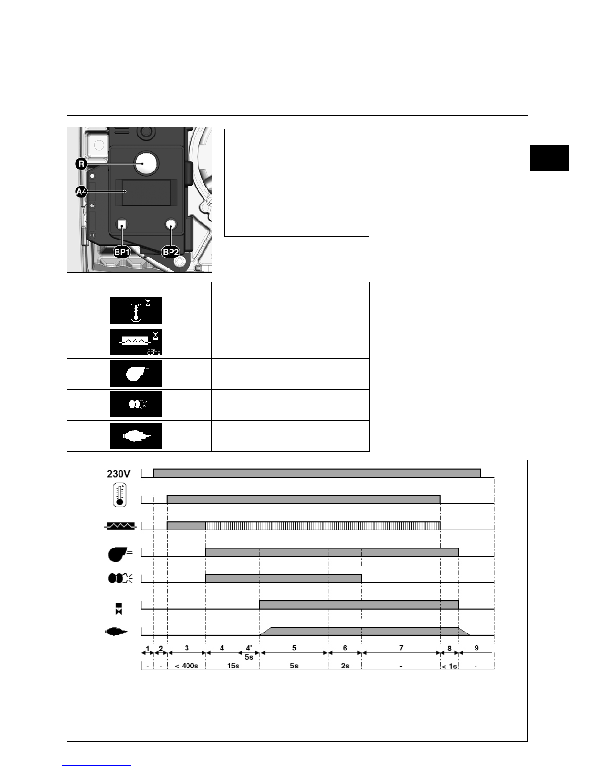
Branderautomaat TCH 1xx
Fasen werkingsverloop:
1: Geen spanning
2: Spanningsvoeding aanwezig,
geen warmteverzoek
3: Warmteverzoek:
sproeierlijnverwarming
ingeschakeld
4: Voorventilatie: motor
ingeschakeld, ontsteking
ingeschakeld
4': Parasietlichtbewaking
5: Branderstart: magneetventiel
open, vlamvorming,
veiligheidstijd
6: Vlam aanwezig,
naontstekingstijd
7: Branderwerking
8: Einde van het warmteverzoek,
magneetventiel sluit, brander
stopt
9: Stand-by
De oliebranderautomaat TCH 1xx stuurt
en bewaakt de aangeblazen brander.
Door het microprocessorgestuurde
programmaverloop worden uiterst
stabiele tijden bereikt, die onafhankelijk
zijn van schommelingen in netspanning
en omgevingstemperatuur. De
branderautomaat is niet gevoelig voor
onderspanning. Als de netspanning
onder de vereiste minimumwaarde ligt,
schakelt de automaat uit zonder
storingssignaal. Nadat weer een
normale spanning is bereikt, start de
automaat weer automatisch.
Vergrendeling en ontgrendeling
De automaat kan via de resetknop R
worden vergrendeld (in storingstoestand
gebracht) en worden ontgrendeld (uit
storingstoestand gehaald), op
voorwaarde dat netspanning
voorhanden is op de automaat.
Voor het in- of uitbouwen van de
automaat moet het apparaat
spanningsvrij worden gemaakt. De
automaat mag niet worden
geopend of gerepareerd.
De knop R
indrukken
gedurende ...
… veroorzaakt ...
… 1 seconde ... Ontgrendelen van de
automaat
… 2 seconden... Vergrendelen van
de automaat
… 9 seconden... Wissen van de
statistieken van de
automaat
A4 Scherm
BP1 Drukknop 1
Opvraging: Storingscode
BP2 Drukknop 2
Opvraging: Waarden
nl
Page 6

03/2011 - Art. Nr. 4200 1016 4000C6
Werking
Oliebranderpomp
De gebruikte oliebranderpomp is een
zelfaanzuigende tandwielpomp, die als
tweestrengenpomp via een
ontluchtingsfilter moet worden
aangesloten. In de pomp zijn
aanzuigfilters en oliedrukregelaars
ingebouwd. Vóór de inbedrijfstelling
moeten manometers voor druk- 4 en
onderdrukmetingen 5 worden
gemonteerd.
1 Aanzuigaansluiting
2 Retouraansluiting
3 Drukaansluiting
4 Manometeraansluiting oliedruk
5 Manometeraansluiting onderdruk
6 Oliedrukregeling
10 Elektrische aansluiting
magneetventiel
Y1 Oliemagneetventiel
AS47D
BFP21L3
Page 7

03/2011 - Art. Nr. 4200 1016 4000C 7
Werking
Aansluitschema
Aansluitsokkel
Stekker nr.
Klem
Stekker nr.
Klem
Afstandsontgrendeling
Aarde
Sproeierlijnverwarming
Vlamcontrole
Stroomvoeding L1
Aanduiding storing
Ontsteking
Brandermotor
Magneetventiel
Klem Benaming Stekker nr. Klem Benaming Stekker nr.
1 Aarde
11
14 Fase brandermotor
4
2 Signaal vlamdoofveiligheid 15 Aarde
3 Fase 16 Neutraal
4 Signaal afstandsontgrendeling
20
17 L1 Magneetventiel netaansluiting
1
5 Fase 18 Aarde
6Fase
25
19 Neutraal
7 Sproeierlijnverwarming/vrijgavecontact 20 Neutraal
5
8 Aarde 21 Fase onstekingstransformator
9 Neutraal 22 Aarde
10 Fase
6
23
10
11 Aarde 24
12 Neutraal 25 Fase storingsaanduiding
21
13 Aarde 26 Neutraal
nl
Page 8

03/2011 - Art. Nr. 4200 1016 4000C8
Montage
Brandermontage
Branderinbouwstand
Controles vóór de inbedrijfstelling
Montage van de brander
De branderflens 3 is voorzien van
langwerpige gaten en kan worden
gebruikt voor een diameter van de
gatencirkel gaande van 150 tot 170 mm.
De afmetingen voldoen aan EN 226.
Door verschuiven van de buizensteun 2
op de branderbuis kan de insteekdiepte
van de menginrichting worden
aangepast aan de afmetingen van de
verbrandingsruimte. De insteekdiepte
blijft ongewijzigd bij het in- en
uitbouwen.
Via de buizensteun 2 wordt de brander
op de aansluitflens en dus aan de ketel
bevestigd. De verbrandingsruimte wordt
hierdoor dicht afgesloten.
Inbouwen:
• Aansluitflens 3 met bouten 4 aan de
ketel bevestigen
• Buizensteun 2 aan de branderbuis
monteren en met een schroef 1
bevestigen. Schroef 1 met een koppel
van max. 6 Nm vastdraaien.
• Brander enigszins draaien, in de flens
invoeren en met schroef 5 bevestigen.
Uitbouwen:
• Bout 5 losdraaien
• Brander uitdraaien en uit de flens
trekken.
Olieaansluiting
De meegeleverde olieslangen zijn al
aangesloten op de oliebranderpomp.
Om verwisseling te voorkomen is de
toevoerslang speciaal gemarkeerd. De
olieaansluiting wordt gerealiseerd via
een ontluchtingsfilter. Het filter moet
dusdanig worden geplaatst dat een
vakkundige slanggeleiding is
gegarandeerd.
De slangen mogen geen knikpunt
vertonen.
Voor de olieleiding moet een koperbuis
DN 4 (4x6) worden gebruikt.
CH: Polyamide-olieleiding DN4,
DIN 16773, Art. nr. 501183.
Voor de maximale lengtes van de
zuigleiding en de aanzuighoogten: zie
de richtlijn voor het ontwerp en de
dimensionering van installaties met
zuiginrichting. Deze richtlijn is onderdeel
van de ontwerpbeginselen van ELCO.
De zuigleiding wordt bij vierkante tanks
tot 5 cm en bij cilindrische tanks tot 10
cm over de tankbodem gevoerd.
Elektrische aansluiting
De elektrische installatie en de
aansluitwerkzaamheden mogen
uitsluitend door een erkend
elektrotechnicus worden uitgevoerd.
Daarbij dienen de geldende
voorschriften en bepalingen in acht te
worden genomen. Deze brander omvat
elektronische componenten; het is aan
te bevelen vóór de installatie een
automatische differentieelschakelaar
van het type A te voorzien, om
zwerfstromen met een
gelijkstroomcomponent op te sporen.
• Controleren of de netspanning met de
opgegeven werkingsspanning van
230 V, 50 Hz overeenstemt.
• Zekering voor de brander: 10 A
De brander en de warmteproducerende
uitrusting worden via een zevenpolige
stekkerverbinding 1 aangesloten.
Controles vóór de inbedrijfstelling
Volgende punten op de installatie
controleren:
- De waterdruk in het
verwarmingscircuit
- Circulatiepompen in werking
- Secundaire-luchtvoorziening in de
schoorsteen in werking (indien
voorhanden)
- Stroomverzorging (230V) naar het
schakelbord van de ketel is
gegarandeerd
- Het oliepeil in de tank
- Aansluitingen van de olieslangen
- (toevoer/retour, dichtheid)
- Olieventielen open
- Instellingen van de menginrichting van
de brander
- Instelling van de onstekingselektroden
- Instelling van de thermostaten
Vóór inbedrijfstelling olie met handpomp
aanzuigen. Brander inschakelen voor de
inbedrijfstelling. Voor volledige
ontluchting, de ontluchtingsschroef op
het oliefilter openen. Hierbij mag een
onderduk van 0,4 bar niet worden
overschreden. Als het filter volledig met
olie gevuld is en de olie zonder bellen
uitstroomt, de brander uitschakelen.
Ontluchtingsschroef sluiten.
Page 9

03/2011 - Art. Nr. 4200 1016 4000C 9
Inbedrijfstelling
Instelgegevens
Luchtregeling
De hierboven vermelde instellingen zijn
basisinstellingen. De
fabrieksinstelgegevens zijn vet omrand.
Met deze instellingen kan normaal
gesproken de brander in bedrijf worden
genomen.
In ieder geval de instelwaarden
zorgvuldig controleren. Correcties
vanwege de installatie kunnen
noodzakelijk zijn.
Gunstige verbrandingswaarden zijn te
bereiken door het gebruik van de
volgende sproeiers:
Danfoss 45° S, 60° S
Steinen 45° S, 60° S
Fluidics 45° S, 60° S
De luchtregeling wordt gerealiseerd op
twee plekken:
- Aan de drukzijde van de ventilator door
middel van een luchtdoseertrommel
- In de branderkop door middel van de
stuwschijf en het mondstuk van de
branderbuis.
De luchtdoseertrommel heeft een lineaire
regelkarakteristiek en wordt bediend
door verdraaien van de regelknop 103B.
De ingestelde waarde kan via de
instelschaal worden gecontroleerd.
De luchtregeling in de branderkop
beïnvloedt behalve de luchthoeveelheid
ook de mengzone en de luchtdruk in de
branderbuis. Verdraaien van schroef 3
- naar de rechterkant = meer lucht
- naar de linkerkant = minder lucht
Op de schaalverdeling Y kan de stand
van de stuwschijf worden gecontroleerd.
De stand van de stuwschijf (maat C)
komt overeen met de waarde op de
schaal Y.
Het justeren op 0 wordt in de fabriek
uitgevoerd.
Als bijstellen of een nieuwe justering
nodig is, dient als volgt te werk worden
gegaan:
• Dekplaat demonteren, daartoe de
springveren aan de binnenkant
losmaken
• Schaal Y door in- of uitdraaien in de
gewenste stand brengen.
• Dekplaat weer monteren.
De aanzuigluchtgeleiding 6 wordt in de
fabriek op 1 ingesteld.
Stand 1 = max. ventilatordruk
Stand 5 = min. ventilatordruk
In gevallen waar een hoge ventilatordruk
een nadeel is, bijvoorbeeld bij sterke
onderdruk in de haard, kan de druk
worden verminderd door de geleiding
van aanzuiglucht te veranderen:
• De bevestigingsschroef 7 losdraaien
• De geleiding van aanzuiglucht op een
nieuwe waarde instellen
• Schroef weer aanspannen.
nl
45°S 60°S
21 1.8 - 0.50 11 6 6 7 1
27 2.3 - 0.60 11 10 10 9 1
38 3.2 - 0.85 11 15 15 14 1
31 2.6 - 0.60 11 10 10 10 1
38 3.2 0.75 - 11 15 15 14 1
40 3.4 0.85 - 11 10 10 13 1
46 3.9 1.00 - 11 15 15 15 1
52 4.4 1.10 - 11 20 20 18 1
58 4.9 1.25 - 11 5 10 8 -
72 6.1 1.50 - 11 10 15 11 80 6.7 1.75 - 11 15 20 13 -
VL1.40/P
VL1.42
VL1.55
VL1.55 P
VL1.95
Maat
Y
mm
Maat
C
mm
Luchtregeling
Schaalwaarde
A
anzuiglucht-
geleiding
Stand
Pomp-
druk
bar
Brander
Brande rverm ogen
kW
Oliedebiet
kg/h
Sproeier
Danfoss
GpH
Page 10

03/2011 - Art. Nr. 4200 1016 4000C10
Inbedrijfstelling
De brander inregelen
Oliedrukregeling
Werkingscontrole
Brander starten
Vóór de start van de brander olie met de
handpomp aanzuigen, tot het filter volledig
gevuld is.
Vervolgens brander starten door het
inschakelen van de ketelregelaar. Om de
olieleiding tijdens de voorventilatiefase
volledig te ontluchten, de ontluchtingsbout op
het oliefilter openen. Hierbij mag de
onderdruk niet lager zijn dan 0,4 bar. Als de
olie zonder gasbellen uitstroomt en het filter
volledig met olie gevuld is,
ontluchtingsschroef sluiten.
Explosiegevaar!
Tijdens het inregelen continu CO, CO
2
en
roetemissies controleren. Bij CO-vorming
verbrandingswaarden optimaliseren. COgehaltes mogen 50 ppm niet
overschrijden.
Instelling brandervermogen
• Via de drukregelaar de oliedruk
overeenkomstig het gewenste
brandervermogen instellen. Hierbij continu
de verbrandingswaarden controleren (CO,
CO
2
, roettest). Indien nodig
luchthoeveelheid aanpassen, zo nodig
stap voor stap.
Verbrandingswaarden optimaliseren
Zo nodig verbrandingswaarden via instelling
van de stuwschijfstand (maat Y)
optimaliseren.
Hierdoor kunnen startgedrag, pulsatie en
verbrandingswaarden worden beïnvloed.
Bij reductie van de schaalwaarde Y stijgt de
CO
2
-waarde, het startgedrag wordt echter
harder.
Indien nodig luchthoeveelheidwijziging door
aanpassing van luchtklepstand
compenseren.
Let op: Minimaal noodzakelijke
rookgastemperatuur in acht nemen
volgens opgave van de ketelfabrikant en
overeenkomstig eisen rookgaswegen ter
voorkoming van condensatie.
Werkingscontrole
Een veiligheidstechnische controle van
de vlambewaking moet zowel bij de
eerste inbedrijfstelling als ook na
revisies of langere stilstand van de
installatie worden uitgevoerd.
- Startpoging met verduisterde
vlamdoofveiligheid: na het einde van
de beveiligingstijd moet de
branderautomaat op storing
schakelen!
- Starten met verlichte
vlamdoofveiligheid: na 10 seconden
voorventilatie moet de
verbrandingsautomaat op storing
schakelen!
- Normale start; als de brander in bedrijf
is, vlamdoofveiligheid verduisteren:
na nieuwe start en nieuw einde van de
veiligheidstijd moet de
verbrandingsautomaat op storing
schakelen!
1 Aanzuigaansluiting
2 Retouraansluiting
3 Drukaansluiting
4 Manometeraansluiting oliedruk
5 Manometeraansluiting onderdruk
6 Oliedrukregeling
10 Elektrische aansluiting
magneetventiel
Y1 Oliemagneetventiel
Oliedrukregeling
De oliedruk, en daarmee het
brandervermogen, wordt met de
oliedrukregelaar 6 in de pomp ingesteld.
Draaien naar
- rechts: drukverhoging
- links: drukverlaging
Ter controle moet op
manometeraansluiting 4 een
manometer worden aangesloten,
schroefdraad R1/8“.
Onderdrukcontrole
De vacuümmeter voor de
onderdrukcontrole moet op aansluiting 5
worden aangesloten, R1/8". Hoogst
toegestane onderdruk 0,4 bar. Bij een
hogere onderdruk verdampt de
stookolie, waardoor krassende geluiden
in de pomp ontstaan en de pomp schade
oploopt.
Pompfilter reinigen
Het filter bevindt zich onder het
pompdeksel. Om het te reinigen moet,
na het losdraaien van de schroeven, het
deksel worden gedemonteerd.
• Pompdekselafdichting controleren en
zo nodig vervangen.
AS47D
BFP21L3
Page 11

03/2011 - Art. Nr. 4200 1016 4000C 11
Service
Onderhoud
Servicewerkzaamheden aan de ketel
en brander worden uitsluitend door
een erkende verwarmingsmonteur
uitgevoerd. Om een regelmatige
uitvoering van het onderhoud te
waarborgen, moet aan de gebruiker
van de installatie het afsluiten van
een onderhoudscontract worden
aanbevolen.
Opgelet
• Vóór onderhouds- en
schoonmaakwerkzaamheden, stroom
uitschakelen.
Controle van de rookgastemperatuur
• Regelmatig de rookgastemperatuur
controleren.
• Ketel reinigen, als de
rookgastemperatuur de waarde van
de inbedrijfstelling met meer dan 30°C
overschrijdt.
• Om de controle te vereenvoudigen
een rookgasthermometer
aanbrengen.
Onderhoudsstanden brander
• Na het losdraaien van schroeven 1
kan de basisplaat in twee
onderhoudsstanden worden
opgehangen.
Stand 1
Als voorbeeld voor het vervangen van
de sproeierlijn:
• Olieaansluiting 12 losdraaien
• Stekkerverbinding 9 afkoppelen
• Elektrodenblok 10 verwijderen.
1 Bevestigingsschroeven
2 Ophangopening
3 Ontstekingstranformator
5 Oliebranderautomaat
6 Oliebranderpomp
7 Sproeierlijn
8 Vlamdoofveiligheid
9 El. aansluiting sproeierlijn
10 Elektrodenblok
11 Regelschroef branderkop
12 Olieaansluiting, sproeierlijn
13 Sproeier
14 Stuwschijf
15 Luchtturbine
Onderhoudswerkzaamheden aan de
brander
Onderhoudsstand 1
• De olieleidingscomponenten (slangen,
pompen, sproeiertoevoerleiding)
alsook hun verbindingen controleren
op lekkages en tekenen van slijtage.
Eventueel vervangen.
• De elektrische aansluitingen en
verbindingskabels controleren op
beschadigingen. Eventueel
vervangen.
• Pompfilter controleren en eventueel
reinigen.
Onderhoudsstand 2
• Ventilatorturbine en behuizing reinigen
en controleren op beschadigingen.
• Menginrichting controleren en
reinigen.
• Stuwschijf demonteren.
• Oliesproeier vervangen.
• Ontstekingselektroden controleren,
eventueel bijstellen of vervangen.
• Menginrichting monteren. Instelmaten
(zie pagina 9) in acht nemen.
• Brander monteren.
• Brander starten, rookgasgegevens
controleren, eventueel
branderinstellingen corrigeren.
• Werkingscontrole vlamdoofveiligheid
(zie pagina10) uitvoeren.
Stand 2
Bijvoorbeeld voor het vervangen van de
sproeiers en de luchtturbine. In die stand
hoeft de sproeierlijn niet leeg te worden
gemaakt om de sproeiers te vervangen.
Montage van de luchtturbine
Bij vervanging van de motor en de
luchtturbine, het volgende
positioneringsschema in acht nemen.
De binnenste flens A van de luchtturbine
moet ter hoogte van de basisplaat B
worden aangebracht. Een liniaal tussen
de schoepen van de turbine voeren en A
en B op dezelfde hoogte brengen,
tapeind aan de turbine aantrekken
(onderhoudsstand 2).
nl
Réinitialisation de l’indicateur de
maintenance
Le symbole de maintenance apparaît
sur l’afficheur du coffret après 30 000
démarrages. C’est pourquoi il est
nécessaire, après chaque entretien, de
réinitialiser le compteur de
maintenance. Pour ce faire, appuyer
pendant au moins 9 secondes sur le
bouton de déverrouillage du coffret.
Page 12

03/2011 - Art. Nr. 4200 1016 4000C12
Service
Storingen verhelpen
Oorzaken en verhelpen van storingen
Bij storingen moeten eerst de
basisvoorwaarden voor een goede
werking worden gecontroleerd:
1. Is er stroom aanwezig?
2. Is er stookolie in de tank?
3. Staan alle afsluitkranen open?
4. Zijn alle regel- en
veiligheidstoestellen, zoals
ketelthermostaat,
droogloopbeveiliging,
eindschakelaar etc., ingesteld?
Als de storing na controle van de
hiervoor genoemde punten niet kan
worden verholpen, test dan de met de
afzonderlijke branderonderdelen
samenhangende functies.
De veiligheidsonderdelen mogen niet
worden gerepareerd, maar dienen te
worden vervangen door onderdelen met
hetzelfde nummer.
Gebruik alleen originele
onderdelen van de fabrikant.
Voor onderhouds- en
reinigingswerkzaamheden, de
stroom uitschakelen.
Na elke ingreep de
verbrandingswaarden onder
werkingsomstandigheden
controleren (deur van stookruimte
gesloten, kap gemonteerd, enz.).
Meetwaarden in documenten
verwarmingsruimte noteren.
Symbool Storing Oorzaak Verhelpen
Geen aanvraag naar
warmte
Thermostaten defect of
ontregeld.
thermostaten instellen of vervangen
Brander start niet na
thermostaatuitschakeling.
Er is geen storingsmelding
op de branderautomaat.
Geen of te lage
netspanning.
Storing van de automaat
Oorzaak van te lage spanning of van
stroomonderbreking opsporen.
De automaat vervangen.
Brander start bij
inschakeling heel kort, en
schakelt uit
Automaat werd opzettelijk
vergrendeld.
Automaat weer ontgrendelen.
Brander start en schakelt
na voorventilatie uit
Parasietlicht bij
voorventilatie-/
voorontstekingsfase
Ontstekingsvonken controleren/elektrode
instellen/vervangen
Oliemagneetventiel controleren/vervangen
Brander start en schakelt
na openen van de
magneetventielen uit
Geen vlam na afloop van
de veiligheidstijd
Oliepeil in de tank controleren.
Tank eventueel bijvullen.
Ventielen openen.
Oliedruk en werking van de pomp, koppeling,
filter, magneetventiel controleren.
Ontstekingscircuit, elektrode-instelling
controleren. Elektroden reinigen/vervangen.
Vlamdoofveiligheid reinigen/vervangen.
Indien nodig, volgende onderdelen
vervangen:
Ontstekingselektroden/ontstekingskabel/
ontstekingstrafo/sproeier/pomp/
magneetventiel/branderautomaat.
Vlamuitval tijdens de
werking
Vlam dooft tijdens de
werkingsfase
A4 Scherm
BP1 Drukknop 1
Opvraging: Storingscode
BP2 Drukknop 2
Opvraging: Waarden
Page 13

03/2011 - Art. Nr. 4200 1016 4000C 13
Service
Aanduiding onderhoudsinterval
Aanduiding olievoorraad
Gedurende de werking kunnen na enige
tijd de volgende inlichtingen verschijnen:
Dat betekent dat het
tijd is voor
onderhoud door een
vakman.
Als de installateur
zijn
telefoonnummer
heeft opgetekend,
dan verschijnt dat,
alsook het
nummer van het
afgesloten
onderhoudscontract
(toegankelijk via het
storingsmenu)
Om het telefoonnummer te wijzigen:
• Door indrukken van BP1 het
storingsmenu oproepen en de
uitlezing door verder bedienen van
BP1 doorlopen tot het gewenste
pictogram verschijnt.
• Op BP2 drukken om de wijziging in te
geven: het eerste cijfer knippert.
• De waarde (van 0 tot 9) kiezen door
herhaald drukken van BP1.
• Op BP2 drukken om te bevestigen.
• De procedure herhalen tot het laatste
cijfer.
Na het bevestigen van het laatste cijfer,
wordt het volledige pictogram
gedurende 5 sec. weergegeven. Daarna
verschijnt opnieuw de werkingsuitlezing.
Om het contractnummer te wijzigen:
• Door indrukken van BP1 het
storingsmenu oproepen en door
verder bedienen de uitlezing
doorlopen tot het gewenste pictogram
"Contractnummer" verschijnt.
• Op BP2 drukken om de wijziging in te
voeren: het eerste cijfer knippert.
• De waarde (van 0 tot 9) kiezen door
herhaald drukken van BP1.
• Op BP2 drukken om te bevestigen.
• De procedure herhalen tot het laatste
cijfer.
Na het bevestigen van het laatste cijfer,
wordt het volledige pictogram
gedurende 5 sec. weergegeven. Daarna
verschijnt opnieuw de werkingsuitlezing.
De aanduiding van de olievoorraad is
eveneens toegankelijk:
Sproeiergrootte
(veranderbare
waarde)
(0,5 - 1,5)
Pompdruk
(veranderbare
waarde)
(8,0 - 17,0)
Stookoliehoeveelh
eid in de tank
(veranderbare
waarde)
Schatting van de
stookoliehoeveelh
eid in de tank
(berekende waarde)
Hiertoe, met de brander in werking,
als volgt te werk gaan:
• De knop BP1 ten minste 5 seconden
lang ingedrukt houden: Het
pictogramm van de sproeiergrootte
wordt weergegeven.
Om de sproeiergrootte te wijzigen:
• Op BP2 drukken om de wijziging in te
geven: het cijfer knippert.
• De waarde (sproeiergrootte, in stappen
van 0,05 US GAL/h) door herhaald
indrukken van BP1
uitkiezen.
• Op BP2 drukken om te bevestigen.
Op het scherm verschijnt vervolgens de
pompdruk.
Om de waarde van de pompdruk te
veranderen:
• Op BP2 drukken om de wijziging in te
geven: het cijfer knippert.
• De waarde
(in stappen van 0,5 bar) door herhaald
drukken van BP1 verhogen.
• Op BP2 drukken om te bevestigen.
Op het scherm wordt vervolgens de
stookoliehoeveelheid weergegeven
(stookolievoorraad).
Voor het invoeren van de
stookolievoorraad:
• Op BP2 drukken om de wijziging in te
geven: het cijfer knippert.
• De waarde (4 cijfers tussen 0 en 9)
invoeren met herhaald drukken van
BP1.
• Op BP2 drukken om te bevestigen.
Op het scherm verschijnt vervolgens een
schatting van de stookoliehoeveelheid in
de tank. Die waarde verandert naar
verloop van tijd in functie van de
hierboven ingevoerde waarde en van de
looptijd van de brander.
A4 Scherm
BP1 Drukknop 1
Opvraging: Storingscode
BP2 Drukknop 2
Opvraging: Waarden
nl
Page 14

03/2011 - Art. Nr. 4200 1016 4000C14
Overview
Contents
Page
Overview Contents.................................................................. 14
Important notes....................................................... 14
Burner description...................................................15
Function Heating, operating and safety function ..................16
Automatic combustion control unit..........................17
Oil burner pump ..................................................... 18
Allocation chart, connection socket......................... 19
Assembly Burner assembly, burner installation position ......... 20
Electrical/oil connection .......................................... 20
Checks before commissioning................................ 20
Commissioning Setting data, combustion head check ..................... 21
Air regulation,......................................................... 21
Burner adjustment, oil pressure regulation .............22
Operating check......................................................22
Service Maintenance ........................................................... 23
Troubleshooting ......................................................24
Maintenance frequency indicator,
fuel oil stock indicator.............................................. 25
Important notes
VL 1.40/P/42/55/55P/95 burners are
designed for the combustion of domestic
fuel oil in accordance with national
standards:
AT: ÖNORM C1109: standard or low
sulphur
BE: NBN T52.716: standard or NBN
EN 590: low sulphur
CH: SN 181160-2: domestic fuel oil
and low-sulphur eco fuel oil
DE : DIN 51603-1: standard and low
sulphur.
The design and function of the burners
meet standard EN 267.
Assembly, commissioning and
maintenance must be carried out only by
authorised specialists and all applicable
guidelines and regulations must be
observed.
Burner description
The VL 1.40/P/42/55/55P/95 burner is a
single-stage, fully-automatic
monoblock-type burner. It is suitable for
use, within its range of performance,
with boilers complying with EN 303 or
hot-air generators in line with DIN 4794,
DIN 30697 or EN 621.
Use for any other application requires
the approval of ELCO.
Scope of delivery
The burner packaging also contains:
1 connection clamping flange with
insulation
1 bag containing installation fittings
1 bag containing Technical
Documentation
The following standards should be
observed in order to ensure safe,
environmentally sound and energyefficient operation:
EN 226
Connection of vaporising oil and forced
draught gas burners to the heat
generator
EN 60335-2
Safety of electrical equipment for
domestic use
Place of installation
The burner must not be used in rooms
exposed to aggressive vapours (e.g.
hairspray, tetrachloroethylene or carbon
tetrachloride), large amounts of dust, or
high levels of air humidity (e.g. in laundry
rooms).
If no connection to an air exhaust
system is provided for the air supply,
there must be a supply air inlet
measuring:
DE: up to 50kW: 150 cm
2
per additional kW: + 2.0 cm
2
CH: QF [kW] x 6= ...cm2; but at least
200 cm
2
.
Variations may arise as a result of local
regulations.
We can accept no warranty liability
whatsoever for loss, damage or injury
caused by any of the following:
- Inappropriate use.
- Incorrect assembly or repair by the
customer or any third party, including
the fitting of non-original parts.
Provision of the system and the
operating instructions
The firing system manufacturer must
supply the operator of the system with
operating and maintenance instructions
on or before final delivery. These
instructions should be displayed in a
prominent location at the point of
installation of the heat generator, and
should include the address and
telephone number of the nearest
customer service centre.
Notes for the operator
The system should be inspected by a
specialist at least once a year. It is
advisable to take out a maintenance
contract to guarantee regular servicing.
Declaration of conformity
for forced-draught oil burner
We, the works certified with nr AQF030
F-74106 ANNEMASSE Cedex
declare under our sole responsibility
that the products
VL 1.40/P
VL 1.42
VL 1.55
VL 1.55P
VL 1.95
comply with the following standards:
EN 50165
EN 55014
EN 60335
EN 60555-2
EN 60555-3
EN 267
Belgian royal decree dated 08/01/2004
In accordance with the stipulations of
the following European Directives
98 / 37 /EECMachinery Directive
89 /336 /EECEMC directive
2006 /95 /ECLow Voltage Directive
92 /42 /EECEfficiency directive
these products bear the CE marking.
Annemasse, 27th October 2008
M. SPONZA
Page 15

03/2011 - Art. Nr. 4200 1016 4000C 15
Overview
Burner description
A1 Oil combustion system
A4 Display
B3 Flame monitor
M1 Electric motor for pump and blower
wheel
pL Air pressure nipple
T1 Ignition transformer
Y Graduated scale
Y1 Solenoid valve.
3 Air regulation in the burner head
5 Fastening screws for equipment plate
7 Mounting bracket
8 Housing
9 7-pin connecting socket (covered)
14 Burner hood
15 Pipe bracket with connecting flange
and insulation
16 Release knob
102 Fuel-oil pump
103B Air regulation
105 Hoses
113 Air intake box
en
Page 16

03/2011 - Art. Nr. 4200 1016 4000C16
Function
Heating function
Operating function
Safety function
Principle diagram
1 Oil burner pump, complete
2 Oil pressure regulator
3 Oil burner pump
4 Solenoid valve
5 Nozzle rod (with heating
on VL1.40/P and VL1.55P)
6 Burner head
7 Baffle plate
8 Linearised air metering drum
10 Blower
11 Burner motor
Heating function
(only on VL1.40/P and VL1.55P)
If the system demands heat, the preheater is switched on first.
When the oil preheating temperature is
reached, a thermostat in the pre-heater
activates the program sequence. The
heating time with cold start is
approximately 2 minutes.
Operating function
- If heat is requested by the boiler
regulator, the automatic oil
combustion control unit starts the
program sequence.
- The motor starts, the igniter is
switched on and the preventilation
period of 15 seconds commences.
- During the preventilation period, the
furnace is monitored for flame signals.
- At the end of the preventilation period,
the fuel-oil solenoid valve opens and
the burner starts.
- The igniter remains switched off while
the burner is in operation.
Controlled shutdown
- Boiler regulator interrupts heat
request.
- The fuel-oil solenoid valve closes and
the flame is extinguished.
- Burner motor switches off.
- Burner enters standby.
Safety function
A safety shutdown occurs:
- if a flame signal is present during
preventilation (parasitic flame
monitoring)
- if no flame is produced within 5
seconds (safety time) of start-up (fuel
authorisation)
- if no flame is produced after an
unsuccessful restart attempt in the
event of flame failure during
operation.
A safety shutdown is indicated by the
malfunction lamp lighting up and it is
then only possible to reenable the
burner by pressing the reset button after
the cause of the malfunction has been
rectified.
For further information, see the
automatic combustion control unit
description.
Page 17

03/2011 - Art. Nr. 4200 1016 4000C 17
Symbol Designation
Waiting for heat request
Waits for pre-heater
(for burner with pre-heater)
Burner motor on
Start of ignition
Flame present
Function
Automatic combustion control unit TCH 1xx
Functional sequence phases:
1: No voltage
2: Power supply on, no heat
request
3: Heat request: Pre-heater on
4: Preventilation: motor on,
ignition on
4: Parasitic flame monitoring
5: Burner start: solenoid valve off,
flame production, safety time
6: Flame present, post-ignition
period
7: Burner operation
8: End of heat request, solenoid
valve closes, burner stop
9: Standby
The TCH 1xx fuel oil control and safety
unit controls and monitors the forced
draught burner. The microprocessorcontrolled program sequence ensures
maximum stability of time periods,
regardless of fluctuations in the power
supply or ambient temperature. The
design of the automatic combustion
control unit protects it from the effects of
brownouts. Whenever the supply
voltage drops below its rated minimum
level, the control unit shuts down - even
in the absence of a malfunction signal.
The control unit switches itself back on
again once the voltage has returned to
normal levels.
Locking and unlocking the system
The control unit can be locked (switched
to malfunction) and unlocked
(malfunction cleared) by pressing the R
reset button, provided the system is
connected to the mains power supply.
Always disconnect the power
supply before installing or
removing the control unit. Do not
attempt to open or carry out
repairs on the control unit.
Pressing and
holding the R
button for ...
... leads to ...
… 1 second... Unlocking of the
control unit
... 2 seconds.... Locking of the
control unit
... 9 seconds.... Clearance of control
unit statistics
A4 display
BP1 push-button 1
Request: fault code
BP2 push-button 2
Request: values
en
Page 18

03/2011 - Art. Nr. 4200 1016 4000C18
Function
Oil burner pump
The oil burner pump used is a selfpriming gear pump, which must be
connected as two-line pump via a bleed
filter. There is an intake filter and an oil
pressure regulator integrated in the
pump. Pressure gauges for pressure
measurements 4 and negative pressure
measurements 5 must be connected
before the equipment is commissioned.
1 Suction intake connection
2 Return connection
3 Pressure connection
4 Oil pressure gauge connection
5 Negative pressure gauge
connection
6 Oil pressure regulator
10 Solenoid valve electrical
connection
Y1 Fuel-oil solenoid valve
AS47D
BFP21L3
Page 19

03/2011 - Art. Nr. 4200 1016 4000C 19
Function
Allocation chart
Connection socket
Connector
no.
Terminal
Connector
no.
Terminal
Remote unlocking
Earth
Pre-heater
Flame monitor
L1 power supply
Malfunction light
Firing
Burner motor
Solenoid valve
Terminal Designation Connector no. Terminal Designation Connector no.
1Earth
11
14 Burner motor phase
4
2 Flame monitor signal 15 Earth
3 Live 16 Neutral
4 Remote release signal
20
17 L1 solenoid valve network-side
1
5Live 18Earth
6Live
25
19 Neutral
7 Pre-heater/release contact 20 Neutral
5
8 Earth 21 Ignition transformer phase
9 Neutral 22 Earth
10 Live
6
23
10
11 Earth 24
12 Neutral 25 Fault display phase
21
13 Earth 26 Neutral
en
Page 20

03/2011 - Art. Nr. 4200 1016 4000C20
Assembly
Burner assembly
Burner installation position
Checks before commissioning
Burner assembly
The burner flange 3 is equipped with
elongated holes and can be used with a
hole circle diameter of 150 - 170 mm.
These dimensions comply with EN 226.
Sliding the pipe bracket 2 on the burner
pipe makes it possible to adjust the
installed depth of the combustion head
to the geometry of the combustion
chamber concerned. The installed depth
remains the same during fitting and
removal.
Pipe bracket 2 secures the burner to the
connecting flange and therefore to the
boiler. This completely seals off the
combustion chamber.
Installation:
• Secure connecting flange 3 to the
boiler using screws 4
• Fit pipe bracket 2 to the burner pipe
and secure using screw
1. Tighten screw 1 to a maximum
torque of 6 Nm.
• Turn the burner slightly, guide it into
the flange and secure using screw 5.
Removal:
• Loosen screw 5
• Turn the burner out and pull it out of
the flange.
Oil connection
The oil hoses supplied are already
connected to the oil burner pump. The
supply hose is individually marked to
reduce the risk of swapping the hoses.
The oil connection is made by means of
a bleed filter. The filter must be located
in such a way that the correct hose
routing cannot be impaired.
The hoses must not kink.
Cu pipe DN 4 (4x6) should be used as a
fuel-oil tube.
CH: Polyamide fuel-oil tube DN4,
DIN 16773, item no. 501183.
For threshold values for suction line
lengths and suction heights, see the
guideline for planning and dimensioning
plants with suction installations. This
guideline is an integral part of the ELCO
planning criteria.
The suction conduit is passed up to 5 cm
above the tank floor in cubic tanks, and
up to 10 cm above the tank floor in
cylindrical tanks.
Electrical connection
The electrical installation and
connection work must only be carried
out by an authorised electrical specialist.
All applicable rules and regulations must
be observed.
This burner contains electronic
components; it is advisable to connect a
type A FI multipole switch upstream of
the system to detect error currents with
a direct current component.
• Check to ensure that the power supply
voltage is as specified (230 V, 50 Hz)
• Burner fuse: 10 A
The burner and heat generator are
connected by a 7-pin connector 1.
Checks before commissioning
Check the following points on the
system:
- Water pressure in heating circuit
- Circulation pumps in operation
- Additional air device in flue operable (if
present)
- Power supply (230 V) to the boiler
control panel is ensured
- Oil level in tank
- Oil hose connections
- (feed/return, tightness)
- Open fuel-oil valves
- Burner combustion head settings
- Ignition electrode settings
- Thermostat settings
Before start-up, draw up oil with a hand
pump. Switch on the burner for start-up.
Open the bleed screw at the oil filter to
allow the oil line to bleed fully. Negative
pressure should not drop below 0.4 bar.
Switch off the burner once the oil comes
out free of bubbles and the filter is
completely full of oil. Close the bleed
screw.
Page 21

03/2011 - Art. Nr. 4200 1016 4000C 21
Start up
Setting data for
air regulation
The settings above are basic settings.
The factory-set adjustment values are
outlined in bold. These adjustment
values are normally suitable for
commissioning the burner.
Always check the adjustment values on
a case by case basis.
System-specific corrections may be
necessary.
Favourable combustion values can be
achieved using the following nozzles:
Danfoss 45° S, 60° S
Steinen 45° S, 60° S
Fluidics 45° S, 60° S
Air is regulated at two points:
- On the pressure side of the ventilator
via an air metering drum
- In the burner head via the baffle plate
and burner pipe nozzle.
The air metering drum has a linear
regulating characteristic and is operated
by turning regulating knob 103B. The
value set can be checked on the control
dial.
The regulation of air in the burner
head influences not only the airflow but
also the mixing zone and the air
pressure in the burner pipe. Turn
screw 3.
- clockwise = more air
- anti-clockwise = less air
The position of the baffle plate can be
controlled on dial Y.
The baffle plate position (dimension C)
corresponds to the value on the Y scale.
It is adjusted to 0 in the factory.
If readjustment is required, proceed as
follows:
• Remove the cover plate by loosening
the catch springs from the inside.
• Move the Y scale to the required
position by screwing in or out.
• Refit the cover plate.
The air intake adjuster 6 is set at the
factory to 1.
Position 1 = max. blower pressure
Position 5 = min. blower pressure
In cases where a higher blower pressure
proves a disadvantage, e.g. large
negative pressure in the combustion
chamber, the pressure can be reduced
by adjusting the air intake adjuster:
• Loosen adjustment screw 7.
• Set air intake adjuster to the new
value.
• Tighten the screw again.
45° S 60° S
21 1,8 - 0,5 11 6 6 7 1
27 2,3 - 0,6 11 10 10 9 1
38 3,2 - 0,85 11 15 15 14 1
31 2,6 - 0,6 11 10 10 10 1
38 3,2 0,75 - 11 15 15 14 1
40 3,4 0,85 - 11 10 10 13 1
46 3,9 1 - 11 15 15 15 1
52 4,4 1,1 - 11 20 20 18 1
58 4,9 1,25 - 11 5 10 8 -
72 6,1 1,5 - 11 10 15 11 80 6,7 1,75 - 11 15 20 13 -
A i r regulat ion
scale value
Air intake
adjuster
setting
VL1.40
VL1.40P
VL1.42
Danfoss
GpH no zzl e
Pump
pressure
bar
Dimension
Y
mm
Dimension
C
mm
Burner output
kW
Oil
throughput
kg/h
Burner
VL1.55
VL1.55P
VL1.95
en
Page 22

03/2011 - Art. Nr. 4200 1016 4000C22
Start up
Adjusting burner output
Oil pressure regulation
Operating check
Burner start
Before starting the burner, draw oil in
using a hand pump until the filter is
completely filled.
Then start the burner by switching on the
boiler regulator. Open the bleed screw
on the oil filter to allow the oil line to
bleed fully during the preventilation
phase. The negative pressure must not
fall below 0.4 bar. Close the bleed screw
when the filter is completely filled with oil
and oil is flowing out without bubbles.
Risk of air blast!
Continuously check CO, CO
2
and
soot emissions when adjusting the
output of the burner. Optimise combustion values in the event of CO formation. CO must not exceed 50 ppm.
Burner output adjustment
• Use the pressure regulator to adjust
the oil pressure in accordance with the
burner output desired. Monitor the
combustion values continuously as
you do so (CO, CO2, soot test). Adjust
the airflow gradually if necessary.
Optimising combustion values
Optimum combustion values can be
achieved by adjusting the position of the
baffle plate (dimension Y) if necessary.
Doing this can have an effect on starting
characteristics, pulsation and
combustion values.
Any reduction in scale value Y increases
the CO
2
value. However, starting
characteristics become harsher.
Compensate for the change in airflow if
necessary by adjusting the air flap
position.
N.B.: Observe the minimum required
flue gas temperature specified by the
boiler manufacturer and the
requirements demanded of flue gas
ducts for avoiding condensation.
Operating check
Flame monitoring must be checked for
safety as part of initial commissioning
and also after servicing or if the system
has been out of operation for any
significant period of time.
- Starting attempt with flame monitor
unlit: the automatic combustion
control unit must switch to malfunction
at the end of the safety time
- Start with flame monitor lit: the
automatic combustion control unit
must switch to malfunction after 10
seconds of preventilation
- Normal start-up: flame monitor goes
out when burner in operation: the
automatic combustion control unit
must switch to malfunction after the
restart and end of the safety time
1 Suction intake connection
2 Return connection
3 Pressure connection
4 Oil pressure gauge connection
5 Negative pressure gauge
connection
6 Oil pressure regulator
10 Solenoid valve electrical
connection
Y1 Fuel-oil solenoid valve
Oil pressure regulation
The oil pressure, and therefore burner
output, is adjusted using oil pressure
regulator 6 in the pump.
Turn to
- right: to increase pressure
- left: to reduce pressure
Connect a pressure gauge at point 4
(with R1/8" thread).
Checking negative pressure
The vacuum meter for checking
negative pressure must be connected to
point 5, R1/8". Maximum permissible
negative pressure is 0.4 bar. At higher
negative pressures, the fuel oil gasifies,
which causes scraping noises in the
pump and ultimately leads to pump
damage.
Cleaning the pump filter
The filter is located under the pump
cover. To be able to clean the filter, it is
necessary to loosen the screws and
remove the cover first.
• Check the pump cover seal and
replace it if necessary.
AS47D
BFP21L3
Page 23

03/2011 - Art. Nr. 4200 1016 4000C 23
Service
Maintenance
Burner and boiler servicing must only
be carried out by a professionally
qualified heating engineer. The
system operator is advised to take
out a service contract to guarantee
regular servicing.
Please observe the following points:
• Disconnect the electrical supply before
carrying out any maintenance or
cleaning work.
Checking the exhaust gas
temperature
• Check the flue gas temperature at
regular intervals.
• Clean the boiler if the flue gas
temperature is more than 30°C above
the value measured at the time of
commissioning.
• To simplify the check, use a flue gas
temperature indicator.
Burner maintenance positions
• After removing the screws 1, the
equipment plate can be hung in two
maintenance positions.
Position 1
For example, for replacing the nozzle
rod:
• Loosen oil connection 12
• Disconnect connector 9
• Remove electrode block 10
1 Fastening screws
2 Mounting opening
3 Ignition transformed
5 Oil combustion system
6 Oil burner pump
7Nozzle rod
8 Flame monitor
9 El. connection for nozzle rod
10 Electrode block
11 Regulating screw for combustion
head
12 Oil connection, nozzle rod
13 Nozzle
14 Baffle plate
15 Blower wheel
Maintenance on the burner
Maintenance position 1
• Check oil supply components (tubes,
pumps, oil feed tube) and their connections for leaks or signs of wear,
replace if necessary.
• Check electrical connections and con-
nection cables for damage, replace if
necessary.
• Check pump filter and clean if neces-
sary.
Maintenance position 2
• Clean blower wheel and housing and
check for damage.
• Check and clean the combustion
head.
• Remove baffle plate.
• Replace oil nozzle.
• Check ignition electrodes, readjust or
replace as necessary.
• Fit combustion head. Observe adjust-
ment dimensions (see page 21).
• Fit burner.
• Start burner, check flue gas data,
correct burner settings if necessary.
• Perform flame monitor function check
(see page 22).
Position 2
For instance, for replacing the nozzle
and blower wheel . This position avoids
having to empty the nozzle rod when the
nozzle is changed.
Blower wheel assembly
Observe the positioning diagram below
when replacing the motor and blower
wheel. The inside flange A of the blower
wheel must be fitted at the same level as
the equipment plate B. Insert a straight
edge between the wing of the blower
wheel and set A and B to the same
height, tighten the set screw on the
blower wheel (maintenance position 2).
en
Réinitialisation de l’indicateur de
maintenance
Le symbole de maintenance apparaît
sur l’afficheur du coffret après 30 000
démarrages. C’est pourquoi il est
nécessaire, après chaque entretien, de
réinitialiser le compteur de
maintenance. Pour ce faire, appuyer
pendant au moins 9 secondes sur le
bouton de déverrouillage du coffret.
Page 24

03/2011 - Art. Nr. 4200 1016 4000C24
Service
Troubleshooting
Fault diagnosis and repair
In the event of a malfunction, first check
that the prerequisites for correct
operation are fulfilled:
1. Is the system connected to the
power supply?
2. Is there oil in the tank?
3. Are all shut-off valves open?
4. Are all control and safety devices,
such as the boiler thermostat, lowwater detector, limit switch, etc.
adjusted correctly?
If the cause of the malfunction cannot be
ruled out by the checks described
above, check the functions associated
with individual burner parts.
Safety components must not be
repaired. They must always be replaced
with parts with the same order number.
Only use original spare parts.
Disconnect the electrical supply
before carrying out any
maintenance or cleaning work.
After any work in the system, check
combustion under normal operating
conditions (doors closed, cover
fitted, etc.). Enter the measurement
values in the boiler room
documentation.
Symbol Symbol Fault Cause Remedy
No heat request Thermostats defective or
incorrectly adjusted
Adjust the thermostats, replace if necessary.
Burner does not start after
thermostat shutdown.
No malfunction indicated
on the automatic
combustion control unit.
Drop in supply voltage or
power failure.
Control unit malfunction.
Check the cause of the fall in voltage or the
power failure.
Replace the control unit.
Burner starts at switch-on
for very short period
and then shuts down
The control unit has been
intentionally locked.
Reset control unit.
Burner starts and then
shuts down after
preventilation
Parasitic flame during
preventilation/
pre-ignition phase
Check ignition sparks/adjust or replace
electrode
Check/replace fuel-oil solenoid valve
Burner starts and then
shuts down after the
solenoid valves have
opened
No flame signal at end of
safety time
Check the oil level in the tank.
Top tank up as required.
Open the valves.
Check the oil pressure and the operation of
the pump, coupling, filter, solenoid valve.
Check ignition circuit, electrode adjustment.
Clean/replace electrodes.
Clean/replace flame monitor.
Replace the following items as required:
Ignition electrodes / ignition cables / ignition
transformer / nozzle / pump / solenoid valve /
automatic combustion control unit.
Flame extinguishing
during operation
Flame goes out during
operating phase
A4 Display
BP1 Push-button 1
Request: fault code
BP2 Push-button 2
Request: values
Page 25

03/2011 - Art. Nr. 4200 1016 4000C 25
Service
Maintenance frequency indicator
Fuel oil stock indicator
After a certain period of operation, the
following information may be displayed:
This means that
maintenance must
be carried out by a
specialist.
If the fitter has
registered his
telephone number,
then this appears,
as well as the
number of the
completed service
contract (accessible
via the fault menu)
To change the telephone number
• Call up the fault menu by pressing
BP1, then keep pressing the button to
scroll through BP1 until the desired
pictogram is displayed.
• Press BP2 to enter a change in the
pictogram: the first figure flashes.
• Select the value (from 0 to 9) by
repeatedly pressing BP1.
• Confirm by pressing BP2.
• Repeat the operation until you reach
the last figure.
After confirming the last figure, the
complete pictogram is displayed for 5
seconds, then the control unit returns to
the operating screen.
To change the contract number
• Call up the fault menu by pressing
BP1, then keep pressing the button to
scroll through until the desired
pictogram «contract number» is
displayed.
• Press BP2 to enter a change in the
pictogram: the first figure flashes.
• Select the value (from 0 to 9) by
repeatedly pressing BP1.
• Confirm by pressing BP2.
• Repeat the operation until you reach
the last figure.
After confirming the last figure, the
complete pictogram is displayed for 5
seconds, then the control unit returns to
the operating screen.
The fuel oil stock indicator can be
accessed:
Nozzle size (value
can be changed)
(0.5 - 1.5)
Pump pressure
(value can be
changed)
(8.0 - 17.0)
Quantity of fuel oil
in the tank (value
can be changed)
Estimating the
quantity of fuel oil
in the tank (value
calculated)
To do this while the burner is
operating:
• Press and hold button BP1 for at least
5 seconds: The nozzle size pictogram
is displayed.
To change the nozzle size:
• Press BP2 to enter a change in the
pictogram: the figure flashes.
• Select the value (nozzle size, in
increments of 0.05 US GAL/h) by
repeatedly pressing button BP1.
• Confirm by pressing BP2.
The screen then displays the pump
pressure.
To change the pump pressure value:
• Press BP2 to enter a change in the
pictogram: the figure flashes.
• Increase the value
(in increments of 0.5 bar) by
repeatedly pressing button BP1.
• Confirm by pressing BP2.
The quantity of fuel oil in the tank is then
shown in the display (fuel oil reserve).
To enter the fuel oil reserve:
• Press BP2 to enter a change in the
pictogram: the figure flashes.
• Enter the value (4 figures from 0 to 9)
by repeatedly pressing BP1.
• Confirm by pressing BP2.
The screen then displays an estimate of
the quantity of fuel oil in the tank. The
value changes over time, depending on
the values entered above and the burner
runtime.
A4 Display
BP1 Push-button 1
Request: fault code
BP2 Push-button 2
Request: values
en
Page 26

03/2011 - Art. Nr. 4200 1016 4000C26
Page 27

03/2011 - Art. Nr. 4200 1016 4000C 27
Page 28

03/2011 - Art. Nr. 4200 1016 4000C28
Hergestellt in der EU. Fabriqué en EU. Fabricato in EU.
Angaben ohne Gewähr. Document non contractuel. Documento non contrattuale.
www.elco.net
Hotline
ELCO Austria GmbH
Aredstr.16-18
2544 Leobersdorf
0810-400010
ELCO Belgium nv/sa
Z.1 Researchpark 60
1731 Zellik
02-4631902
ELCOTHERM AG
Sarganserstrasse 100
7324 Vilters
0848 808 808
ELC
O GmbH
Dreieichstr.10
64546 Mörfelden-Walldorf
0180-3526180
ELCO Italia S.p.A.
Via Roma 64
31023 Resana (TV)
800-087887
ELCO Burners B.V.
Amsterdamsestraatweg 27
1411 AB Naarden
035-6957350
OOO «Ariston Thermo RUS LLC»
Bolshaya Novodmitrovskaya
St.bld.14/1 office 626
127015 Moscow -Russia
+7 495 783 0440
 Loading...