

Page 1
en
Operating instructions
VGL4.460 DP
VGL4.610 DP
de, fr................................. 4200 1055 6201
it, nl.................................. 4200 1055 6301
en..................................... 4200 1055 6801
de, fr, it, nl, en................. 4200 1055 6101
......................................... 4201 1011 2500
For specialist installation engineers
Gas burners
......................................... 4200 1075 5001
09/2016 - Art. Nr. 4200 1055 6801A
Page 2

Overview
Contents
Overview Contents ................................................................................................................................................ 2
Operation Gas operation
Assembly Burner assembly .................................................................................................................................... 18
Commissioning Adjustment data gas operation, Adjustment data fuel oil operation ....................................................... 23
Important information ............................................................................................................................... 3
Burner description ................................................................................................................................. 3-4
Operation, Safety function....................................................................................................... 5
TCG 5xx control unit.............................................................................................................6-8
Terminal allocation chart, 230 Volt connection........................................................................ 9
Fuel oil operation
MB-VEF gas train, Fuel oil pump ........................................................................................................... 17
Gas manifold, Pressure take-off pipes ................................................................................................... 19
Checking the burner head...................................................................................................................... 20
Electrical connection, Selection of fuel................................................................................................... 21
Gas connection, Checks before commissioning ....................................................................................22
Air regulation, Gas valve adjustment, Fuel oil pressure regulation ........................................................ 24
Gas operation
Fuel oil operation
Setting the gas pressure switch, Setting the air pressure switc
Saving the adjustment values in the display ..........................................................................................35
Terminal allocation chart, Low voltage connections.............................................................. 10
Operation, Safety function.....................................................................................................11
TCH 2xx control unit.........................................................................................................12-14
Terminal allocation chart, 230 Volt connection...................................................................... 15
Terminal allocation chart, Low voltage connections.............................................................. 16
Pre-setting without flame..................................................................................................25-26
General advice before starting the burner............................................................................. 26
Setting the flame ..............................................................................................................27-29
Operating mode..................................................................................................................... 29
Pre-setting without flame..................................................................................................30-31
General advice before starting the burner............................................................................. 31
Setting the flame ..............................................................................................................32-34
Operating mode..................................................................................................................... 34
h ........................................................... 35
Servicing Maintenance......................................................................................................................................36-37
Gas operation
Troubleshooting................................................................................................................ 38-39
Fuel oil operation
Troubleshooting..................................................................................................................... 40
Fault diagnosis menu ............................................................................................................................. 41
Operating statistics menu..................................................................................................................41-42
09/2016 - Art. Nr. 4200 1055 6801A2
Page 3

en
Overview
Important information
Burner description
Important information
VGL4.460 DP and VGL4.610 DP
burners are designed for the lowpollutant combustion of natural gas and
extra light fuel oil. The design and
function of the burners meet standards
EN 676 and EN 267. They are suitable
for use with all heat generators
complying with standard EN 303 or for
use by hot air generators complying with
standard DIN 4794 or DIN 30697 within
their respective performance range. Any
other type of application requires the
approval of ELCO.
Installation, start-up and maintenance
must only be carried out by authorised
Burner description
VGL4.460 DP and VGL4.610 DP
burners are two-stage fully automatic
monoblock devices. The special design
of the combustion head enables
combustion with low levels of nitrogen
oxide and increased output. Class 3
type-approval in accordance with
EN676 (for gas) and with EN267 (for fuel
oil) certifies that the lowest emission
values have been achieved and means
that the national environmental
regulations have been met
AT: KFA 1995, FAV 1997
CH: LRV 2005
DE: 1.BImSChV
Emissions values may differ, depending
on combustion chamber dimensions,
combustion chamber load and the firing
system (three-pass boilers, boilers with
reverse firing). For specifying warranty
values, the conditions for the measuring
equipment, tolerances and humidity
must be observed.
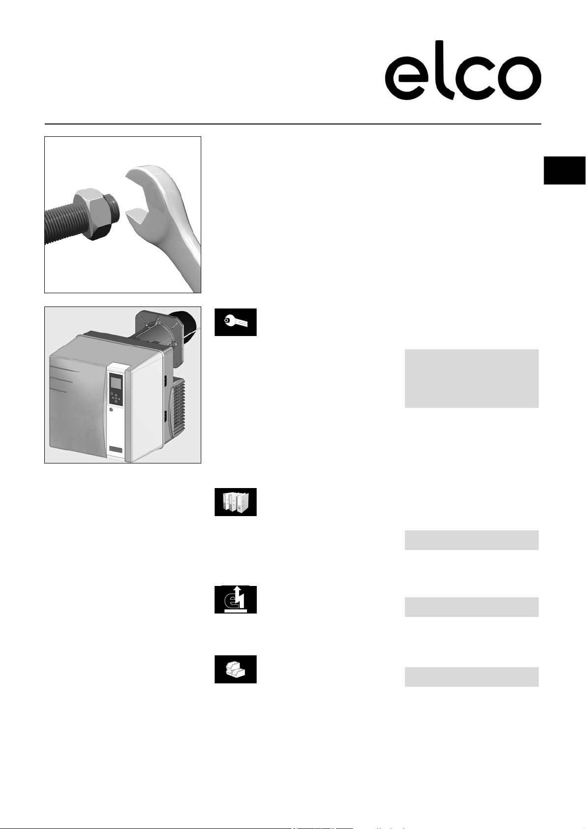
Packaging
The burner is supplied packaged in
three boxes on a pallet:
- Burner housing with operating
instructions, circuit diagram and spare
parts list.
- Burner head with flange seal and
securing screws.
- Compact gas train with integrated filter
specialists and all applicable guidelines
and regulations must be complied with.
The following standards should be
observed in order to ensure safe,
environmentally sound and energyefficient operation:
EN 226
Connection of fuel oil and forceddraught gas burners to a heat generator
EN 60335-1, -2-102
Specification for safety of household
and similar electrical appliances,
particular requirements for gas burning
appliances
Gas lines
When installing the gas lines and trains,
the general directives and guidelines, as
well as the following national
regulations, must be observed:
CH: - G1 instruction text from SSIGE
- EKAS form no. 1942,
liquefied gas directive, part 2
- Cantonal authority guidelines
(e.g. directives for the pilot valve)
DE: - DVGW-TVR/TRGI
Installation location
The burner must not be used in rooms
with aggressive vapours (e.g. hair spray,
tetrachloroethylene, carbon
tetrachloride), high levels of dust or high
air humidity (e.g. laundry rooms).
If no connection to an air exhaust
system is provided for the air supply,
there must be a supply air inlet
measuring:
DE: up to 50 kW: 150 cm
per additional kW: : + 2.0 cm
CH: QF [kW] x 6= ...cm2; but at least
150 cm2.
Variations may arise as a result of local
regulations.
2
2
We accept no responsibility for
damage arising from:
- inappropriate use.
- incorrect installation and/or repair on
the part of the buyer or any third party,
including the fitting of non-original
parts.
Final delivery and instructions for
use
The firing system fitter must supply the
operator of the system with operating
and maintenance instructions on or
before final delivery. These instructions
should be displayed in a prominent
location at the point of installation of the
heat generator, They should include the
address and telephone number of the
nearest customer service centre.
Notes for the operator
The system should be inspected by a
specialist at least once a year.
Depending on the type of installation,
shorter maintenance intervals may be
necessary! It is advisable to take out a
maintenance contract to guarantee
regular servicing.
09/2016 - Art. Nr. 4200 1055 6801A 3
Page 4
Overview
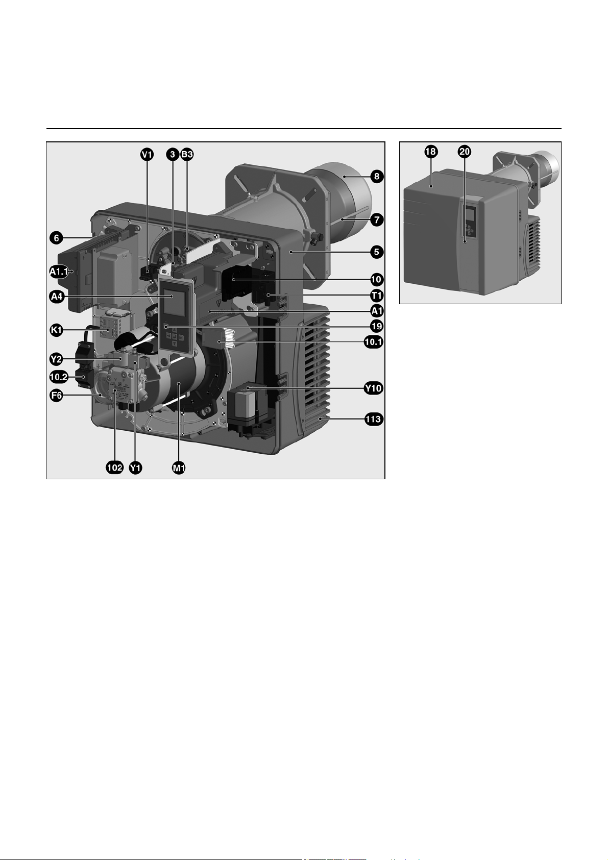
Burner description
A1 Control and safety unit
(Gas operation)
A1.1 Control and safety unit
(Fuel oil operation)
A4 Display
F6 Air pressure switch
K1 Auxiliary motor supply relay
M1 Blower motor
T1 Igniter
V1 Flame detection cell
Y1 Fuel oil solenoid valve, 1
Y2 Fuel oil solenoid valve, 2nd stage
Y10 Air flap servomotor
3 Adjusting screw for dimension Y
5 Housing
6 Plate hanging device
(Maintenance)
7 Combustion chamber pressure
take-off pipe
8 Burner tube
10 7-pin connector
10.1 4 pin connector
10.2 3-pin connector (auxiliary motor
supply relay)
18 Cover
19 Release knob
20 Hood securing screw
102 Fuel oil pump
113 Air intake box
st
stage
09/2016 - Art. Nr. 4200 1055 6801A4
Page 5

en
Compact train
Operation
Gas operation
Operation
Safety function
Description of the function
A pre-ventilation time of 24 seconds
begins when first powering up, after a
power cut or a lockout, after the gas
supply has been cut or after a shutdown
for 24 hours.
During the pre-ventilation time
- the air pressure is monitored
- a check is made for the presence of
any abnormal flame signals.
At the end of the pre-ventilation time
- the ignition is switched on
- the main and safety solenoid valves
are opened.
- burner start-up
Monitoring
The flame is monitored by an IRD cell.
Safety functions
- If no flame is produced when the
burner is started (gas release), the
burner is switched off at the end of the
safety time which lasts no more than
3 seconds and the gas valve closes.
- If the flame is lost during operation, the
gas supply is cut within a second. A
new start-up sequence is activated. If
the burner starts, the operating cycle
starts running. Otherwise a lockout
occurs.
- If there is an air failure during preventilation or operation, a lockout
occurs.
- If there is a gas failure, the burner
either stops or will not start. As soon
as sufficient gas pressure is available
again, the burner restarts.
During the regulator shutdown
- The control thermostat interrupts the
heat request.
- The gas valves close
- The flame goes out
- The blower motor stops
- The burner is ready for operation
Principle diagram
F4 Gas pressure switch
F6 Air pressure switch
Y12 Safety solenoid valve
Y13 Main solenoid valve
1 Thermal shut-off valve (to be
installed by the installer)
104 Gas pressure regulator
106 Screen
108 Gas cut-out valve (to be installed
by the installer)
119pBrGas pressure measuring point at
the valve outlet
119.1Gas pressure measuring point
upstream of the valves
119.2Air pressure measuring point
pF Furnace pressure
pG Gas pressure at the head
pL Air pressure
CH note
In accordance with SSIGE instructions,
it is compulsory to install a gas safety
valve (mark 1) in the pipe
DE Note
In compliance with the reference layout
applicable to boiler rooms, sites with gas
furnaces must be fitted with a thermal
gas shut-off valve (1).
09/2016 - Art. Nr. 4200 1055 6801A 5
Page 6

Operation
Gas operation
TCG 5xx control unit
The TCG 5xx control and safety unit
controls and monitors the forced draught
burner. The microprocessor-controlled
program sequence ensures maximum
stability of time periods, regardless of
fluctuations in the power supply voltage
or the ambient temperature. The
automatic combustion control unit is
designed to cope with brownouts.
Whenever the supply voltage drops
below its rated minimum level (< 185V),
the control unit shuts down - even in the
absence of a malfunction signal. The
control unit switches itself back on again
once the voltage has returned to normal
levels (> 195V).
Pressing the
unlocking button on
the unit for
... 1 second ... the control unit to
... 2 seconds ... the control unit to
... 9 seconds ... the statistics to
… causes …
unlock.
lock.
be deleted
Locking and unlocking
The control unit can be locked (switched
to malfunction mode) by pressing the
unlocking button and unlocked (fault
deleted), provided the unit is connected
to the mains power supply.
Always switch off the power
supply before installing or
removing the control unit. Do not
attempt to open or carry out
repairs on the control unit.
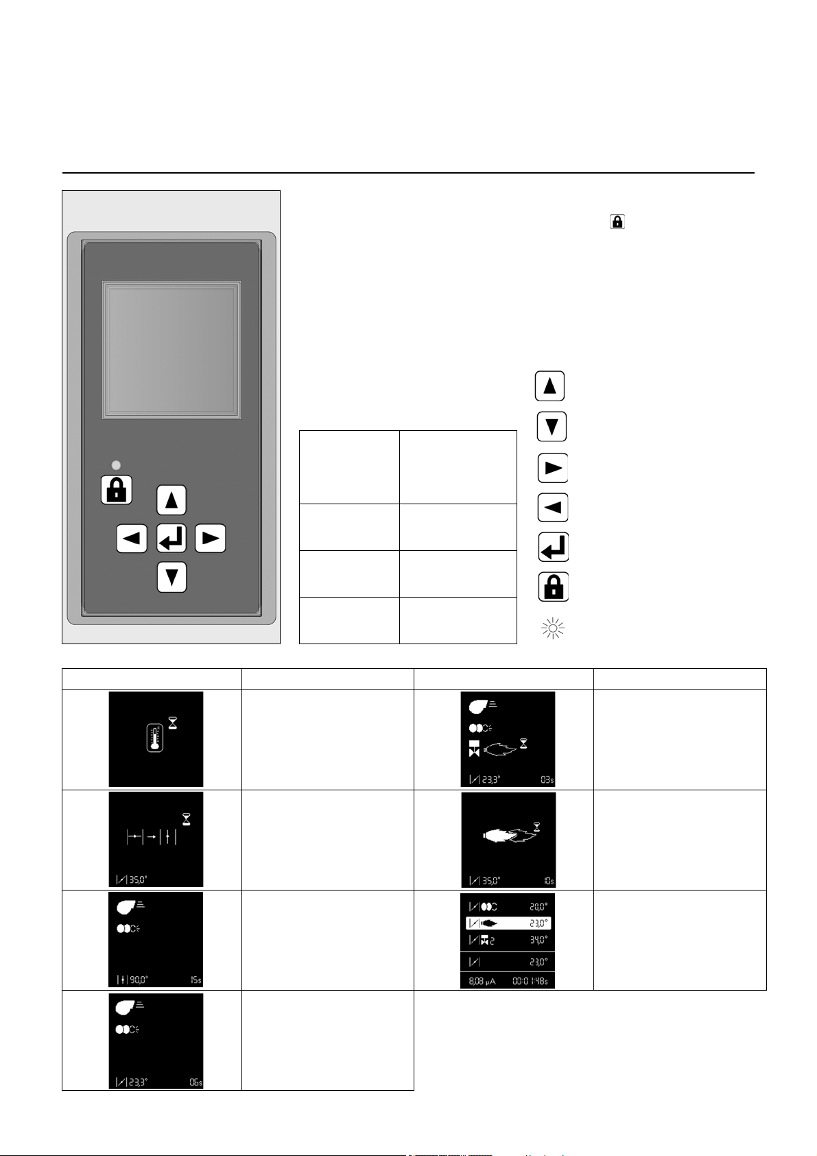
Moves the cursor upwards.
Moves the cursor downwards.
Increases the marked value.
Reduces the marked value.
Modifies/Confirms the value
shown.
Unlocks the control unit.
Red LED (flashes if a fault is
present).
Screen Description Screen Description
Awaiting the heat request from
the boiler
Air flap is forced open for pre-
ventilation.
Pre-ventilation
Closing the air flap to the ignition
position, pre-ignition
Opening the gas valve and
safety time
Flame is present, awaiting
authorisation of regulation
Burner in operation. The lower
cell shows the strength of the
signal and the operating time of
the burner.
09/2016 - Art. Nr. 4200 1055 6801A6
Page 7

en
Operation
Gas operation
TCG 5xx control unit
In parallel with its control and safety
functions, the TCG5xx control unit
allows the following to be set:
(see illustration)
- the position of the air flap during
ignition
- the position of the air flap at minimum
pressure
- the position of the air flap at maximum
pressure
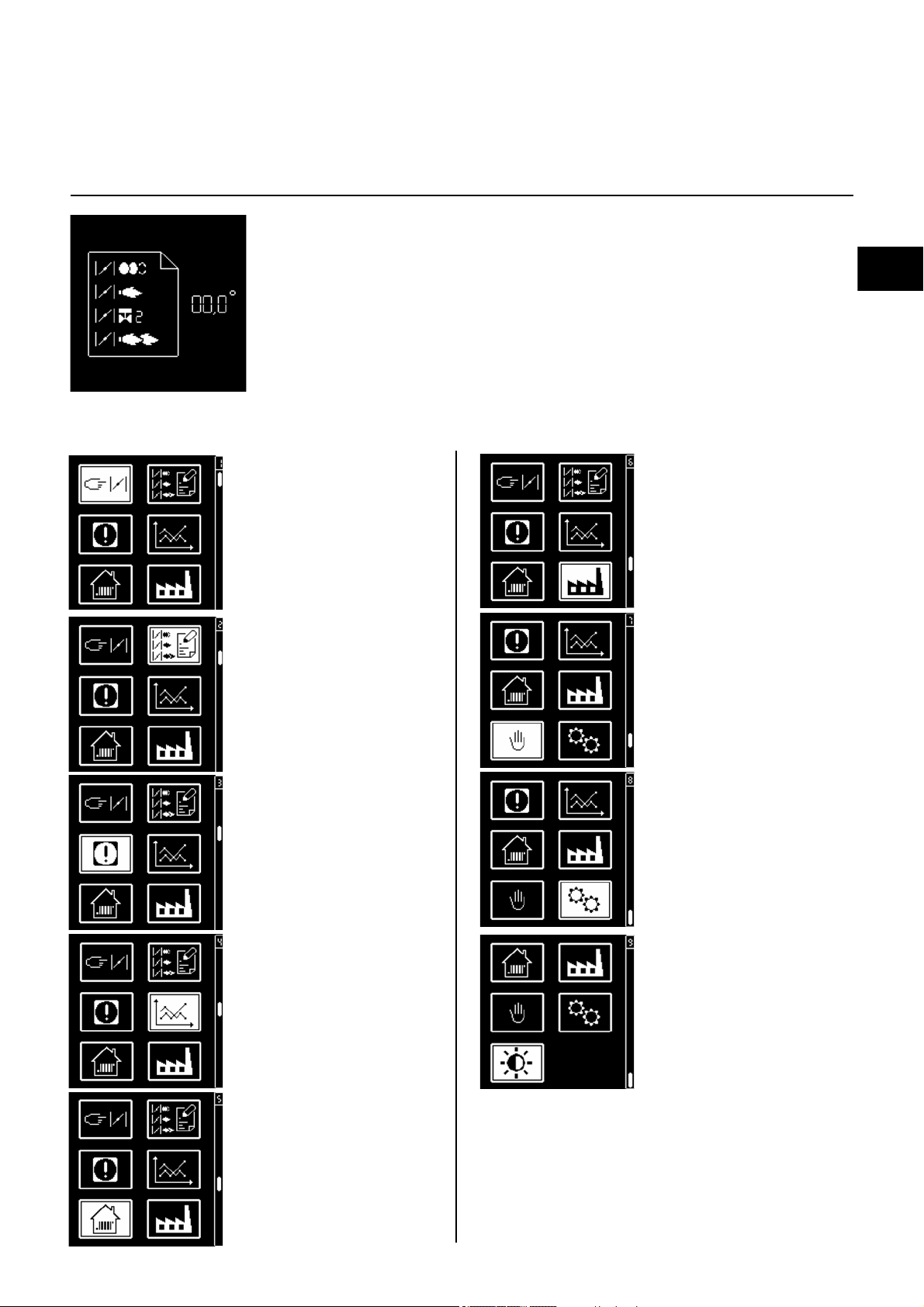
• menu for setting the
servomotor
• menu for storing the
servomotor setting
points in the display
The parameters for the control unit are
set using the display and 5 keys.
Operating values are shown in real time
on the display.
Pressing the keys gives access to 9
menus:
• menu for setting
industrial applications*
• menu for manual control*
• fault diagnosis menu
• operating statistics
menu
• menu for setting/
adjusting the standard
configurations*
• Parameter mode menu*
• Menu for adjusting
screen contrast and
brightness settings
* In these menus, it is
possible to adjust the
control unit's standard
configurations. These
are pre-set in the
factory. No
modifications may be
carried out on-site
without prior
consultation with ELCO.
The access code and
the setting setpoints for
these menus are
available on request.
09/2016 - Art. Nr. 4200 1055 6801A 7
Page 8
Operation
Gas operation
TCG 5xx control unit
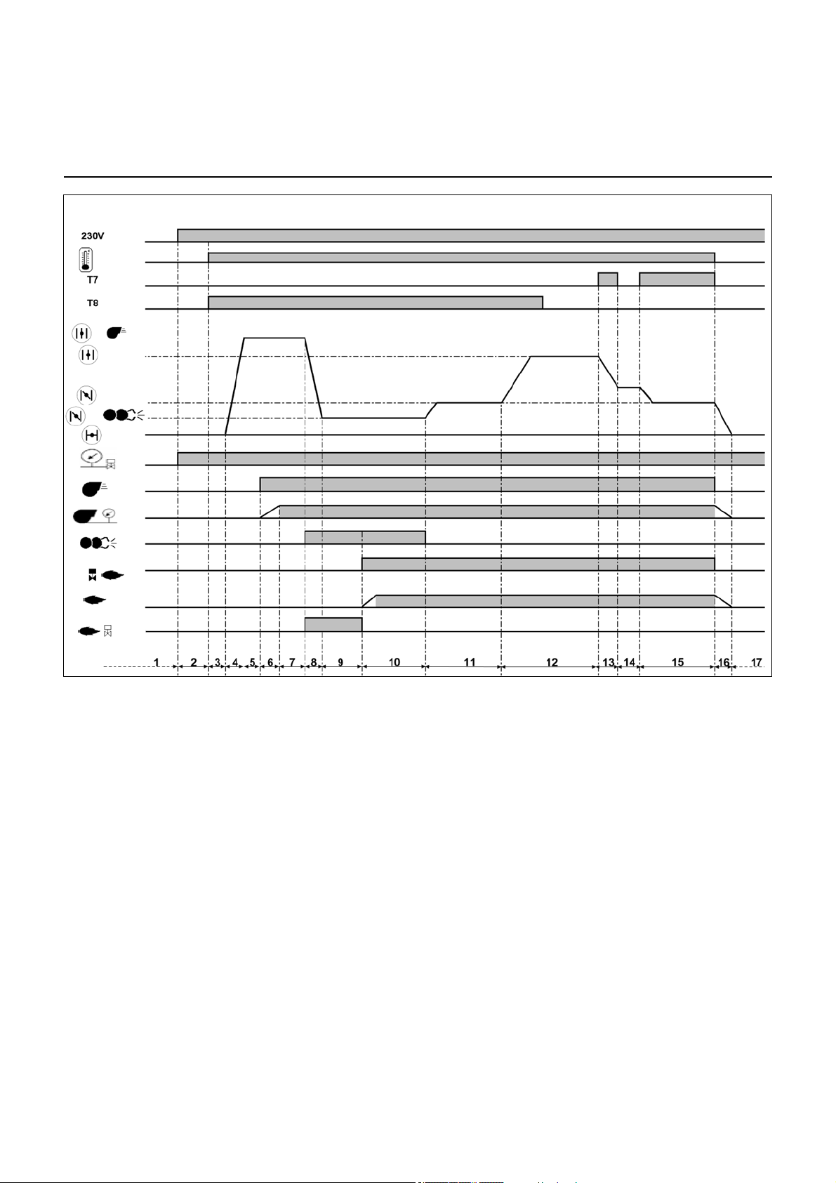
Operating cycle phases:
1: No voltage
2: Powering up, no heat request
3: Heating request
4: Opening an air flap, arrival in pre-
ventilation position
5: Checking the rest status of the air
pressure switch
6: Pre-ventilation: energizing of the
motor, checking the air pressure
7: Pre-ventilation
8: Air flap closes to the ignition position
9: Switching on the igniter, unauthorised
flame monitoring
10:Opening of the solenoid valve, flame
formation, safety time: max. 3 s.
11:Awaiting regulator release
12:Opening the air flap, until the
maximum output is reached
13:Closing of the air flap until the
minimum regulation position is
reached
14:Operation at intermediate regulation
power
15:Operation at minimum regulation
power
16:Regulator shutdown, closure of the
air flap
17:Awaiting a new heating request
09/2016 - Art. Nr. 4200 1055 6801A8
Page 9
en
Operation
Earth
Flame check
Fault
display
Air pressure
switch
Igniter
Burner motor
Connector
Terminal
Terminal
Connector
Remote
unlocking
L1 power
supply
Solenoid valve
Control
thermostat
Heating
request
Earth
Gas pressure
switch
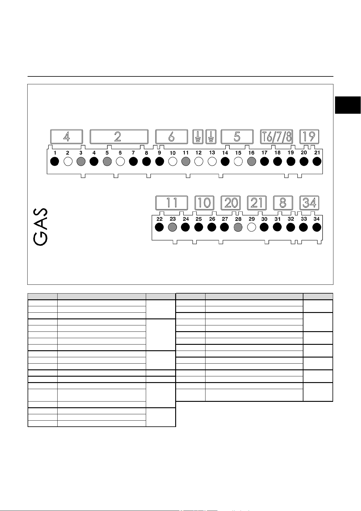
Terminal Description Connector Terminal Description Connector
1 Burner motor live 20 Minimum output thermostat li ve (T1)
2 Earth 21 Heating request signal (option T2)
3 Neutral 22 Flame monitoring signal
4 Solenoid valve live 23 Neutral
5 Neutral 24 Live
6 Earth 25 Air pressure switch signal
7 Solenoid valve live 26 Live
8 Live 27 Live
9 L i ve L1 28 Re mote unlocking si gnal
10 Earth 29 Neutral
11 Ne utral 30 S ignal fault live
12 Earth 31 Live
13 Earth 32 Gas pressure switch signal mini
14 Igniter live 33 Live
15 Earth 34
Gas pressure switch si gnal (if leakage test
present)
16 Neutral
17 Control thermostat live
18 Signal T7
19 Signal T8
8
5
34
T6/7/8
11
2
10
20
6
21
4
19
Gas operation
Terminal allocation chart
230 Volt connection
09/2016 - Art. Nr. 4200 1055 6801A 9
Page 10

Operation
Display-PC interface
Air servomotor
Gas operation
Terminal allocation chart
Low voltage connections
Terminal Description Connector Terminal Description Connector
1 not used
2 not used 19 not used
3 not used 20 not used
4 not used
5 not used 22 not used
6 not used 23 not used
7 not used 24 not used
8 not used 25 not used
9 not used 26 not used
10
11 28
12 29
13 30
Display or PC interface
14 31
15 32
16 33
17
30
27
28
29
16
/
17
18 not used
21 not used
27 not used
Air servomotor
14
33
32
15
09/2016 - Art. Nr. 4200 1055 6801A10
Page 11
en
Operation
Fuel oil operation
Operation
Safety function
Starting the burner
- After heat is requested by the boiler
regulator, the automatic combustion
control unit starts the program
sequence.
- The blower motor starts up, the ignition
switches on.
- Pre-ventilation with air flap open (air
flap is only closed when the burner is
switched off).
- The solenoid valve 6 opens, pressure
set by the partial load regulator 5.
- Flame formation.
- Ignition switches off.
Burner operation, regulation between
partial load and full load
The burner operates with two nozzles
and at one fuel oil pressure for partial
load and one for full load. Fuel oil
pressure is regulated by a pressure
regulator in the pump.
If an increase in load is requested by the
boiler regulator, the burner switches
from partial load to full load after a delay
of at least 13 seconds.
- Air flap 11 is moved to the full load
position by the servomotor.
- When the position of the air flap can be
adjusted, the solenoid valve for the
second nozzles opens.
- The air flap continues to move to the
full load position. The full load is in
operation.
Safety function
A safety shutdown is triggered:
- if a flame signal is detected during preventilation (unauthorised flame
monitoring),
- if no flame is produced within 5
seconds (safety time) of the burner
being started (fuel inlet authorisation),
- if no flame is produced after an
unsuccessful restart attempt in the
event of flame failure during
operation.
A safety shutdown is indicated by the
malfunction lamp lighting up. Once the
cause of the malfunction has been
rectified, it is possible to unlock the
control unit by pressing the reset button.
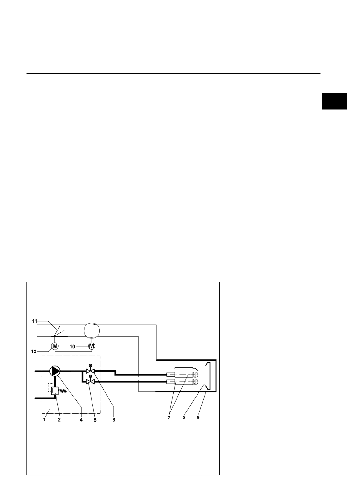
Principle diagram
1 two-stage pump.
2 Fuel pressure regulator (partial
load and full load)
4Pump
5 Magnetic valve (partial load)
6 Magnetic valve (full load)
7 Nozzle line
8 Baffle plate
9Flame tube
10 Burner motor
11 Air flap
12 Air flap electric servomotor
09/2016 - Art. Nr. 4200 1055 6801A 11
Page 12
Operation
Fuel oil operation
TCH 2xx control unit
The TCH 2xx fuel oil automatic
combustion control unit controls and
monitors the forced draught burner. The
microprocessor-controlled program
sequence ensures maximum stability of
time periods, regardless of fluctuations
in the power supply voltage or the
ambient temperature. The automatic
combustion control unit is designed to
cope with brownouts. Whenever the
supply voltage drops below its rated
minimum level (< 185V), the control unit
shuts down - even in the absence of a
malfunction signal. The control unit
switches itself back on again once the
voltage has returned to normal levels
(> 195V).
Pressing and
holding the
unlocking button
for...
... 1 second ... the control unit to
... 2 seconds ... the control unit to
... 9 seconds ... the statistics to be
… causes …
unlock.
lock.
deleted
Locking and unlocking
The control unit can be locked using the
release knob or unlocked as long as
the unit is powered on.
Always switch off the power supply
before installing or removing the
control unit. Do not attempt to
open or carry out repairs on the
control unit.
Moves the cursor upwards.
Moves the cursor downwards.
Increases the marked value.
Modifies/Confirms the value
shown.
Modifies/Confirms the value
shown.
Unlocks the control unit.
Red LED (flashes if a fault is
present).
Screen Description Screen Description
Awaiting the heat request from
the boiler
Air flap is forced open for pre-
ventilation.
Pre-ventilation and pre-ignition
Air flap closes to the ignition
position
Oil valve is opened, safety time
Flame is present, awaiting
authorisation of regulation
Burner in operation. The lower
cell shows the strength of the
signal and the operating time of
the burner.
09/2016 - Art. Nr. 4200 1055 6801A12
Page 13
en
Operation
Fuel oil operation
TCH 2xx control unit
In parallel with its control and safety functions,
the TCH2xx control unit allows the following
to be set:
- the position of the air flap during ignition
- the position of the air flap during the
1st stage
- the position of the air flap during opening
the stage 2 valve (for switching from 1st to
2nd stage)
- the position of the air flap during the
2nd stage
- the position of the air flap during closing the
stage 2 valve (for switching from 2nd to 1st
stage).
• menu for setting the
servomotor
• menu for storing the
servomotor setting
points in the display
The parameters for the control unit are set
using the display and 5 keys. Operating
values are shown in real time on the display.
Pressing the keys gives access to 9 menus:
• menu for setting
industrial applications*
• menu for manual control*
• fault diagnosis menu
• operating statistics
menu
• menu for setting/
adjusting the standard
configurations*
• Parameter mode menu*
• Menu for adjusting
screen contrast and
brightness settings
* In these menus, it is
possible to adjust the
control unit's standard
configurations. These
are pre-set in the
factory. No
modifications may be
carried out on-site
without prior
consultation with ELCO.
The access code and
the setting setpoints for
these menus are
available on request.
09/2016 - Art. Nr. 4200 1055 6801A 13
Page 14

Operation
Fuel oil operation
TCH 2xx control unit
Operating cycle phases:
1: No voltage
2: Powering up, no heat request
3: Heating request
4: Air flap opens to the preventilation
position
5: Pre-ventilation: Switching on the
motor and the igniter
6: Closing the air flap, switching to
the ignition position
7: Unauthorised flame monitoring
8: Starting the burner: opening the
solenoid valve, flame formation,
safety time
9: Awaiting regulator release
10: Opening the air flap, until the
opening position of the 2
nd
stage
valve is reached
11: Operation in 2
12: Closing the air flap, until the
closing of the 2
13: Operation in 1st stage
14: Regulator shutdown, closure of
the air flap to 0°
15: Awaiting a new heating request
nd
stage
nd
stage valve
09/2016 - Art. Nr. 4200 1055 6801A14
Page 15

en
Operation
Earth
Pre-heater
Flame monitor
Fault
display
Air
pressure
switch
Ignition
Burner motor
2nd stage
solenoid valve
Connector
Terminal
Terminal
Connector
Remote
unlocking
L1 power
supply
1st stage
solenoid valve
3rd stage
solenoid valve
2nd stage
thermostat
Heating
request
Earth
Fuel pump
pump unit
Fuel oil operation
Terminal allocation chart
230 Volt connection
Terminal Description Connector Terminal Description Connector
1 Burner motor live
2 Earth 22 Neutral
3 Neutral 23 Live
st
41
5 Earth 25 Not used
6 Neutral 26 Live
72nd stage solenoid valve live
8 Earth 28 Neutral
9 Neutral 29 Signal fault live
10 3
11 Earth 31 Preheater/release contact
12 Neutral 32 Earth
13 Igniter live
14 Earth 34 Live L1
15 Neutral 35 Earth
16 2
17 Signal T7 37 Earth
18 Signal T8 38 Earth
19 1
20 Heating request signal (option T2) 40 Earth
stage solenoid valve live
rd
stage solenoid valve live
nd
stage thermostat phase (T6)
st
stage thermostat live (T1)
4
1
2
3
5
T6/7/8
19
21 Flame monitoring signal
24 Not used
27 Remote unlocking signal
30 Live
33 Neutral
36 Neutral
39 Pump unit live
41 Neutral
11
10
20
21
25
6
35
09/2016 - Art. Nr. 4200 1055 6801A 15
Page 16

Operation
Display-PC interface
Air flap servomotor
Connector
Terminal
Terminal
Connector
Fuel oil operation
Terminal allocation chart
Low voltage connections
Terminal Description Connector Terminal Description Connector
1 Not used
2 Not used 19 Not used
3 Not used 20 Not used
4 Not used
5 Not used 22 Not used
6 Not used 23
7 Not used 24
8 Not used 25
9 Not used 26
10
11 28
12
13
Display-PC interface
14
15
16
17
17
27
28
29
16
18 Not used
21 Not used
Air flap servomotor
27
31
30
15
09/2016 - Art. Nr. 4200 1055 6801A16
Page 17

en
Operation
MB-VEF gas train
Fuel oil pump
1 Electrical connection of solenoid
valves (DIN 43650)
2 Electrical connection of the
gas pressure switch (DIN 43650)
3 Gas pressure switch
4 Inlet flange
5 Pressure measuring nipple
R1/8, upstream of filter (option)
6 Filter (under the cover)
7 Connection for furnace pressure
release pipe pF, R1/8
8 Adjusting screw for V ratio
9 Adjusting screw for zero point
offset N
10 Connection for pressure pipe pL,
R1/8
11 Connection for pressure pipe pBr,
R1/8
12 Outlet flange
13 Pressure take-off pipe pBr
The MBVEF compact gas valve
assembly is a combination of filter, gas/
air ratio regulator, valves and a pressure
switch:
- Screen with 0.8mm mesh
- GWA5 pressure switch
- Servo-pressure control part with
adjustable ratio V, correction of the
zero point offset N and furnace
pressure connection.
- V1 and V2 fast-opening and closing
solenoid valves
Technical data
Input pressure 360 mbar max.
Ambient temperature -15 to +70°C
Voltage 230 V/ 50 Hz Max.
Absorbed output 50 VA
Protection rating IP 54
The pump is a gear pump. It must be
connected as a two-line pump via a
bleed filter. For the connection of the fuel
oil tank and the bleed filter, it is better to
use the single line option. An inta k e fil ter
and one oil pressure regulator are
integrated in the pump. Pressure
gauges for pressure measurements 4
and negative pressure measurements 5
must be connected before the
equipment is commissioned.
1 Vacuum connection G 1/4
2 Return connection G 1/4
3.1 Pump tube connection /
1st stage nozzle line G1/8
3.2 Pump tube connection /
2nd stage nozzle line G 1/8
4,7 Pressure gauge connection
5 Vacuum gauge connection
6 Pressure setting
Y1 Solenoid valve, 1st stage
Y2 Solenoid valve, 2nd stage
09/2016 - Art. Nr. 4200 1055 6801A 17
Page 18

Ø a Ø b c d
190-240 200-270 M10 45°
Assembly
Burner assembly
Preparing the boiler front
• Prepare the burner mounting plate/
boiler door in accordance with the
diagram.
• Establish the internal diameter a of
190-240 mm.
• To mount the burner head bracket, drill
four M10 holes (drill diameter 200 to
270 mm) as shown in the diagram
opposite.
Burner head assembly
• Screw the bolts into the burner fixing
plate/boiler door and position the
insulation material. For a drill hole of
< 270 mm, elongated slots should be
cut to the required dimensions.
• Remove the combustion components
from the head
• Attach the burner head with 4 nuts
(ref. 4). At this point, check that the
gas connection flange is correctly
positioned (on the left or right).
Fitting the burner body
• Remove the cover (2 screws W).
• Do not damage the cells.
• Unscrew the two screws Z on the
burner body completely.
• Bring the burner body into contact after
having swivelled it at least 15° to the
left.
• Engage the two screws Z on the body
into the two lugs provided.
• Tighten the 2 screws.
On boilers with reverse firing, minimum
flame tube insertion depth A should be
observed as per the boiler
manufacturer's instructions.
For assembly in the position with
the volute facing upwards, unclip
the display, turn it over 180°, and
refit it.
Burner tube installation depth and
brickwork surround
Exhaust gas evacuation system
To avoid unpleasant noise emissions,
right-angled connectors should not be
used on the flue gas side of the boiler.
09/2016 - Art. Nr. 4200 1055 6801A18
Page 19

en
Assembly
Gas manifold
Pressure take-off pipes
Gas train assembly
• Check the correct position of the
O-ring B in the gas connecting flange
C.
• Secure the gas train on the burner
head so that the gas train coils are in
the upper vertical position.
• Pay attention to the direction of
circulation.
• Connect the power cable to the gas
train.
Connecting pressure take-off pipes
pF and pL
• Connect the furnace pressure take-off
pL on the burner body and the union
pL on the gas train using the flexible
tube pL (blue), shorten the tube
depending on the assembly scenario.
• Connect the furnace pressure take-off
pF on the burner body and the union
pF on the gas train using the flexible
tube pF (grey), shorten the tube
depending on the assembly scenario.
• Manually screw in the unions (max.
5 Nm) and check tightness.
09/2016 - Art. Nr. 4200 1055 6801A 19
Page 20

Assembly
CDE
VGL4.460/610 DP
633
Checking the burner head
Checking the burner head
• Check the adjustment settings of the
ignition electrode as per the diagrams.
Fitting the combustion components
• Check that the O-Ring J1 is in the
correct position in the gas elbow.
• Insert the combustion components
into the head, tighten the mounting
screw X using an Allen key, then
tighten the lock nut using an openended spanner.
• Thread the ignition cables ZK into the
grommet S.
• Remove the cover.
09/2016 - Art. Nr. 4200 1055 6801A20
Page 21

en
Assembly
Electrical connection
Selection of fuel
All electrical installation and
connection work must only be carried
out by a suitably qualified electrician.
The applicable guidelines and
directives must be observed, as
well as the electrical circuit
diagram supplied with the
burner!
Electrical connection
• Check to ensure that the power supply
is as specified (230V, 50 Hz single
phase with neutral and earth)
Boiler fuse: 6.3 A
Electrical connection
It must be possible to disconnect
the burner from the mains using an
omnipolar shutdown device
complying with the standards in
force. The burner and heat
generator (boiler) are connected
by a 4-pin connector (no. 2) and a
7-pin connector (no. 1).
The diameter of the cables connected to
these connectors must be between 8.3
and 11 mm.
The burner motor has its own
separate power supply (no. 3).
Fuse on the motor circuit: 6 A gM
Connecting the gas train
Connect the gas train to the plugs on the
burner (black to black, grey to grey).
Selection of fuel
Disconnect the power supply before
changing the fuel.
The selection of fuel occurs by
connecting the cable (no. 4):
- for the gas operation on the unit
TCG5
- for the fuel oil operation on the unit
TCH2
In gas operation, it’s essential to
remove the pump coupling (see
picture).
This one must be stored in a visible
place so it can be repositioned when
liquid fuel is to be used.
09/2016 - Art. Nr. 4200 1055 6801A 21
Page 22

Assembly
Gas connection
Checks before commissioning
General regulations applying to the
gas connection
• The gas train must only be connected
to the gas mains by a recognised
specialist.
• The cross-section of the gas line
should be of a size designed to
guarantee that the gas flow pressure
does not drop below the specified
level.
• A manual shut-off valve (not supplied)
must be fitted upstream of the gas
train.
• In Germany, a thermally triggered
shut-off valve (to be installed by the
customer side) must be fitted as
Checks before commissioning
The following must be checked before
initial commissioning:
• That the burner is assembled in
accordance with the instructions given
here.
• That the burner is pre-set in
accordance with the values in the
adjustment table.
• Setting the combustion components.
• The heat generator must be ready for
operation, and the operating
regulations for the heat generator
must be observed.
• All electrical connections must be
correct.
• The heat generator and heating
specified by the draft combustion
ordinance.
It is the responsibility of the fitter or his
representative to obtain approval for the
system at the same time as the burner is
commissioned. Only the fitter or his
representative can guarantee that the
system meets applicable standards and
regulations. The fitter should be in
possession of the corresponding official
permit, and should carry out the
corresponding sealing tests and purge
the system of air.
system must be filled with water and
the circulating pumps must be in
operation.
• The temperature regulator, pressure
regulator, low water detectors and any
other safety or limiting devices that
might be fitted must be connected and
operational.
• The exhaust gas duct must be
unobstructed and the secondary air
system, if available, must be
operational.
• An adequate supply of fresh air must
be guaranteed.
• The heat request must be available.
• Sufficient gas pressure must be
available.
• The fuel supply lines must be
assembled correctly, checked for
leaks and bled.
• A standard-compliant measuring point
must be available, the exhaust gas
duct up to the measuring point must
be free of leaks to prevent anomalies
in the measurement results.
09/2016 - Art. Nr. 4200 1055 6801A22
Page 23

en
Commissioning
Mi ni. Maxi. Igni tion Mini. Maxi. G20 G25 G20 G25 G20 G25
113 290 0 3,1
0034,5
1,3 / 0 1,5 / -0,1 1,28 / 0,1 1,4 / 0,1 1 / 0,1 1,2 / 0
105 338 0 3, 5 0 0 45
1,3 / -0,35 1,4 / -0,1 1,25 / 0,1 1,4 / 0,1 0,95 / 0,1 1,2 / 0,1
101 383 5 3,8 0 0 90 1,3 / -0,35 1,5 / -0,1 1,31 / 0,1 1,4 / 0,1 0,9 / 0,1 1,2 / 0,2
164 385 15 3,4
15 10 40
1,25 / 0 1,75 / 0 1,25 / 0 1,5 / 0 1 / 0 -
218 460 20 4,3 15 15 50
1,5 / -0,5 2 / -1 1,5 / 0 1,75 / -0,5 1,2 / 0 -
199 512 30 4,8 15 15 90 1,5 / -0,5 2 / -1 1,5 / 0 1,75 / -0,5 1,2 / 0 -
VGL4.610
DP
Ai r f l a p
setting
Dimension
Y
( mm)
Burn er
power
kW
Furnace
pressure
pF
(mbar)
Gas valve setti ng
Screw V / Screw N
MB- VEF412 MB- VEF407MB- V E F 4 2 0
VGL4.460
DP
1. stage 2. stage 1. stage 2. stage 1. stage 2. stage 1. stage 2. stage
205 300 25,4 17,3 4,00 2,00 16 16 0 15 20 30 42
210 340 28,7 17, 8 4,00 2,50 16 16 0 15 20 35 56
215 370 31,3 18, 2 4,00 3,00 16,0 16 5 15 20 53 90
190,4 290, 6 16,1 24, 5 4,00 2,00 15 15 0 15 16 25 30
225,5 390, 8 19,0 33, 0 4,50 3,00 15 15 0 15 20 38 50
260,6 521, 1 22,0 43, 9 5,00 5,50 12 12,0 25 15 20 55 90
St age
changeover
Igniti on
Nozzle 60°S
Gph (Danfoss)
kWBurner
Bold : Del iver y s etting; 1kg f uel- oil at 10°C = 11.86kWh
VGL4.460DP
VGL4.610DP
Fuel-oil flow
kg/h
bar
mm
Air flap position
in °
1. stage 2. stage
Adjustment data gas operation
Adjustment data fuel oil operation
Burner power
The adjustment values above are guide
values and facilitate commissioning.
The factory settings are in bold set
against a grey background The final
settings are essential in ensuring that
the burner functions as well as possible
Pump pressure
Setting the burner
When both fuels are available, or failing
that, apply the following principle:
1. Set the gaseous fuel to the boiler
nominal output
2. then set the liquid fuel. The nominal
fuel oil throughput is subject to the
nominal air flow defined in the fuel oil
setting (choice of nozzles and
adjusting the pump pressure).
Dimensi on
Y
Setting the gas pressure switch
• Remove the transparent cover.
• Provisionally set to 15 mbar.
Setting the air pressure switch
• Remove the transparent cover.
• Provisionally set to 1 mbar.
09/2016 - Art. Nr. 4200 1055 6801A 23
Page 24

Commissioning
Air regulation
Gas valve adjustment
Fuel oil pressure regulation
Air regulation
Combustion air is regulated at two
points:
• on the pressure side, using the gap
between the turbulator and the burner
tube.
• on the vacuum side, by the air flap
driven by servomotor Y10.
The regulation of air in the burner head
affects not only the air flow but also the
mixing zone and the air pressure in the
burner tube. Turning screw A
- right: more air
- left: less air
• Adjust dimension Y in accordance with
the settings table.
Air regulation by air flap
Air is regulated on the vacuum side by
an air flap. This is driven by servomotor
Y10.
Gas valve adjustment
V Setting the maximum power
N Setting the minimum power
- For more CO2 turn upwards on the
scale.
- For less CO
scale.
turn downwards on the
2
1 Vacuum connection G 1/4
2 Return connection G 1/4
3.1 Pump tube connection /
1st stage nozzle line G1/8
3.2 Pump tube connection /
2nd stage nozzle line G 1/8
4,7 Pressure gauge connection
5 Vacuum gauge connection
6 Pressure setting
Y1 Solenoid valve, 1st stage
Y2 Solenoid valve, 2nd stage
Fuel oil pressure regulation
The fuel oil pressure is adjusted using
fuel oil pressure regulator 6 for the 1st
stage and for the 2nd stage. To check
the pressure, connect a R1/8" pressure
gauge to connector 4.
Turn
- right: to increase the pressure
- left: to reduce the pressure
Checking the vacuum pressure
The vacuum meter for checking
negative pressure must be connected to
point 5, R1/8". Maximum authorised
vacuum: 0.4 bar. At higher vacuum pressures, the fuel oil gasifies, which causes
scraping noises in the pump and risks
damaging it.
09/2016 - Art. Nr. 4200 1055 6801A24
Page 25

en
Commissioning
Gas operation
Pre-setting without flame
Setting is carried out in 2 phases:
- pre-adjustment without flame
- setting the flame, to fine tune the
settings based on the combustion
results
When the burner is switched on, the
control unit displays the screen below.
• For the next step, press any
button.
The overall view of the menus
is displayed, and the air flap
positions settings menu is
selected.
• Open the settings menu by
pressing the key.
Important
At this point, no setting position for the
servomotor has been defined, therefore
the burner cannot be started under
these conditions.
The control unit then opens the
settings mode. The screen
displays the factory presettings for the different
positions of the air flap (here for
example: for a VGL4.460 DP).
The following positions for the
air flap are presented:
- ignition position (when the
menu is opened, the curser
goes to this position)
- the position of the air flap at
minimum pressure
- the position of the air flap at
maximum pressure
You must now enter the
access code (see the label on
the back of the display)
• Increase or decrease the
value in increments by
repeatedly pressing or
.
• When the first figure has
been set, move the cursor to
the right by pressing .
• Repeat the operation until
you reach the last figure.
• Confirm the access code by
pressing
09/2016 - Art. Nr. 4200 1055 6801A 25
Modifying a settings value for the servomotor position:
- To modify the value of a position, move the cursor to the
corresponding location with the or key.
- Select the value to be modified using the key, the
selected value will flash.
- Increase or decrease the value in increments of 0.1° by
repeatedly pressing or . For large modifications, press
and hold the or key the value will scroll quickly up or
down.
- Confirm the new value using the key. The value stops
flashing.
Page 26

Commissioning
Gas operation
Pre-setting without flame
General advice before starting the burner
End of presetting menu without flame
When all the positions of the servomotor have been determined according to the required
settings, it is then possible to move on to the next section for commissioning - "Setting the flame".
To do this, place the cursor in the lower part of the screen on the symbol and confirm by
pressing the key.
If it is necessary to quit the menu without saving the pre-settings, position the cursor on the
symbol and confirm with the key.
Optimising combustion values
Optimum combustion values can be
achieved by adjusting the position of the
turbulator (dimension Y) if necessary.
Doing this can have an effect on starting
characteristics, pulsation and
combustion values. Any reduction in
dimension Y increases the CO
However, starting characteristics
become harsher.
Compensate for the change in airflow if
necessary by adjusting the air flap
position.
Precautions: To avoid condensation,
observe the minimum required flue
gas temperature specified by the
boiler manufacturer and comply with
the requirements for flue gas ducts.
Risk of deflagration
Continuously check CO, CO
and soot emissions when
adjusting. Optimise
combustion values if CO is
present. The CO level must
not exceed 50 ppm.
value.
2
2
Function check
Flame monitoring must be checked for
safety as part of initial commissioning
and also after servicing or if the system
has been out of operation for any
significant period of time.
- Starting attempt with gas valve closed:
once the safety time has elapsed, the
control and safety unit should indicate
a lack of gas or switch to malfunction
mode.
- Starting with the air pressure switch
closed:
after an 8-second test period, the
burner switches to malfunction mode.
- Starting attempt with air pressure
switch open:
after a 60-second waiting period, the
control and safety unit locks.
- Starting attempt with brief opening of
the air pressure switch during preventilation:
the control and safety unit restarts the
pre-ventilation programme (air
pressure detected again within
60 seconds) ; otherwise a lockout
occurs.
09/2016 - Art. Nr. 4200 1055 6801A26
Page 27

en
Commissioning
Gas operation
Setting the flame
- If the boiler heating request
is not present, the boiler
remains on standby.
In this case, it is still possible to
return to the previous setting
menu "Pre-setting without
flame". To do this, position the
cursor on the symbol and
confirm with the key.
- If a boiler heating request is
present (T1-T2 contact
closed), the burner starts.
The air flap is opened to move
to the pre-ventilation position.
Air pressure switch test
The air flap switches to the
ignition/pre-ignition position.
The fuel valve opens.
Awaiting flame signal
If no flame is detected at the
end of the safety time, the
control unit switches to
malfunction mode.
Pre-ventilation
If the flame is detected
Flame stabilisation
The control unit awaits the
regulation authorisation.
09/2016 - Art. Nr. 4200 1055 6801A 27
Page 28

Commissioning
Gas operation
Setting the flame
Setting the minimum pressure
If the flame has been detected and stabilised, the control unit sets the burner to minimum power
as soon as it receives the regulation authorisation.
- Check the combustion values (CO, CO
(see page 24).
- Read the flame current value.
- Read the gas flow rate on the gas counter.
Modification of the air flow via the "manual output control"
The "manual output control" function allows the burner output to be modified.
To do this, position the cursor on the corresponding line on the display and confirm with the
key. It is then possible to adjust the burner output upwards or downwards using the , keys.
The servomotor reacts in real time. This is why the combustion values must be continuously
monitored.
, soot test). If necessary, adjust screw N on the valve
2
Setting the maximum output
Slowly increase the burner to the maximum output using the "manual power control" function. At
this point, adjust the gas flow using the regulator V on the gas train.
The preset limit values for the minimum output and the maximum output cannot be exceeded. If
necessary, exit the "manual output control" function again using the key and modify the limit
value for the maximum or minimum output.
Definitive limitation of the maximum output position
Limit the maximum opening of the air flap according to the position determined for the maximum
output. In this example, the new position determined for the maximum output is below the value
set manually. Using the "manual output control" function, it is now possible to reduce the burner
output, but this cannot be set above the new maximum position, which here is 50°.
Definitive limitation of the minimum output position
Using the "manual output control" function, reduce the burner output to the minimum output. If
necessary, limit the minimum output position, in the same way as for the maximum output.
Specific function: ignition checking
If the ignition position has been modified, it is possible to carry out a new burner start-up to check
the new ignition position, without having to quit the settings menu.
To do this, after modifying the ignition position, position the cursor on the symbol, and initiate
the new start-up using the key.
09/2016 - Art. Nr. 4200 1055 6801A28
Page 29

en
Commissioning
Gas operation
Setting the flame
Operating mode
Closing the "Setting the flame" menu
The burner setting is now complete. If necessary, it is possible to again correct each of the
settings values. To do this, position the cursor on the value to be modified, using the or key.
Otherwise, at any point, there are 3 possible ways of closing the "Setting the flame" menu, as
follows:
- either restart the burner setting procedure, passing through the presetting phase (without
entering a password). To do this, position the cursor on the symbol and confirm with
the key. All the settings values already saved therefore remain available. This is essential
for testing a new ignition position.
- or: Save the fixed values and end the setting procedure. To do this, position the cursor on the
symbol and confirm with the key . The burner is then ready to operate and can now be
controlled by the boiler regulation.
- or: Quit the settings menu without reaching the end of the setting procedure. To do this, position
the cursor on the symbol and confirm with the key . All the servomotor positions saved
up to this point are recovered by calling up the settings menu again.
Operating mode - Display of the operating status, the flame signal and the operating time
After setting of the burner has been completed, it switches to operating mode.
The burner's instantaneous operating status (operation at minimum or maximum power) is
shown by the cursor.
The lower cell shows the intensity of the signal. The display range is from 0 µA to 13 µA. A good
quality signal is above 8µA.
The following limit values are valid:
• When checking an unwanted flame: the signal must be < 0.7µA
• During the safety time: the signal must be > 1.0µA
• During operation: the signal must be > 8µA
The cell at the bottom right displays the current operating time of the burner.
09/2016 - Art. Nr. 4200 1055 6801A 29
Page 30

Commissioning
Fuel oil operation
Pre-setting without flame
Setting is carried out in 2 phases:
- pre-adjustment without flame
- setting the flame, to fine tune the
settings based on the combustion
results
When the burner is switched on, the
control unit displays the screen below.
• Press any button and the
following screen will appear:
The overall view of the menus
is displayed, and the air flap
positions settings menu is
selected.
• Open the settings menu by
pressing the button .
Important
At this point, no setting position for the
servomotor has been defined, therefore
the burner cannot be started under
these conditions.
The control unit then opens
the settings mode. The screen
displays the factory presettings for the different
positions of the air flap (here
for example: for a VGL 4.460
DP).
The following positions for the
air flap are presented:
- ignition position (when the
menu is opened, the curser
goes to this position)
- position of the air flap during
the 1st stage
- position of the air flap when
the 2nd stage fuel oil valve is
opened
- position of the air flap during
the 2nd stage
You must now enter the
access code (see the label on
the back of the display)
• Increase or decrease the
value in increments by
rep eat edl y p res sin g o r
.
• When the first figure has
been set, move the cursor to
the right by pressing .
• Repeat the operation until
you reach the last figure.
• Confirm the access code by
pressing .
09/2016 - Art. Nr. 4200 1055 6801A30
Modifying a settings value for the servomotor position:
- To modify the value of a position, move the cursor to the
corresponding location with the button or .
- Select the value to be modified using the button , the
selected value will flash.
- Increase or decrease the value in increments of 0.1° by
repeatedly pressing or . For large modifications, press
and hold the or button, the value will scroll quickly up
or down.
- Confirm the new value using the button . The value stops
flashing.
N.B.:
It is possible to set different positions within a large range of
values. However, for safety reasons, the control unit enforces
a minimum interval of 2° between the different positions
(except between the ignition position and the 1st stage).
Page 31

en
Commissioning
Fuel oil operation
Pre-setting without flame
General advice before starting the burner
End of settings menu without flame
When all the positions of the servomotor have been determined according to the required
settings, it is then possible to move on to the next section for commissioning - "Setting the flame".
To do this, place the cursor in the lower part of the screen on the symbol and confirm by
pressing the button .
If it is necessary to quit the menu without saving the pre-settings, position the cursor on the
symbol and confirm with the button .
Preparing the burner start-up
Before starting the burner, draw fuel oil
in using a hand pump until the filter is
completely filled. Then start the burner
by switching on the boiler regulator.
Open the bleed screw on the oil filter to
allow the oil line to bleed fully during the
pre-ventilation phase. The negative
pressure must not fall below 0.4 bar.
Close the bleed screw when the filter is
completely filled with fuel oil and fuel oil
is flowing out without bubbles.
Optimising combustion values
Optimum combustion values can be
achieved by adjusting the position of the
baffle plate (dimension Y) if necessary.
Doing this can have an effect on starting
characteristics, pulsation and
combustion values. Any reduction in
dimension Y increases the CO
However, starting characteristics
become harsher.
Compensate for the change in airflow if
necessary by adjusting the air flap
position.
Precautions: To avoid condensation,
observe the minimum required flue
gas temperature specified by the
boiler manufacturer and comply with
the requirements for flue gas ducts.
value.
2
Risk of air blast!
Continuously check CO, CO
soot emissions when adjusting.
Optimise combustion values if CO is
present. The CO level must not
exceed 50 ppm.
Function check
Flame monitoring must be checked for
safety as part of initial commissioning
and also after servicing or if the system
has been out of operation for any
significant period of time.
- Start attempt with the flame detection
cell obscured:
at the end of the safety time,
the control unit must switch to
malfunction mode!
- Start-up with the flame detection cell lit
up: the automatic combustion control
unit must switch to malfunction mode
after 10 seconds of pre-ventilation.
- Normal start; if the burner is in
operation, cover the flame detection
cell: the automatic combustion control
unit must switch to malfunction mode
after a restart and the end of the safety
time
and
2
If dimension Y needs to be corrected
again when the 2
will be necessary to check the
adjustment values for the 1
nd
stage is adjusted, it
st
stage.
09/2016 - Art. Nr. 4200 1055 6801A 31
Page 32

Commissioning
Fuel oil operation
Setting the flame
- If the boiler heating
request is not present, the
boiler remains on standby.
In this case, it is still possible
to return to the previous
setting menu "Pre-setting
without flame". To do this,
position the cursor on the
symbol and confirm with
the button .
- If a boiler heating request
is present (T1-T2 contact
closed), the burner starts.
The air flap is opened to move
to the pre-ventilation position.
The air flap switches to the
ignition position.
The fuel valve opens.
Awaiting flame signal
If no flame is detected at the
end of the safety time, the
control unit switches to
malfunction mode.
Pre-ventilation and preignition
Flame detected
Flame stabilisation
The control unit awaits the
regulation authorisation.
09/2016 - Art. Nr. 4200 1055 6801A32
Page 33

en
Commissioning
Fuel oil operation
Setting the flame
Setting the 1st stage
If the flame has been detected and stabilised, the control unit sets the burner to the 1st stage as
soon as it receives the regulation authorisation.
- Adjust the fuel oil pressure for the 1st stage depending on the required output, using the
To do this, modify the position of the servomotor in 1st stage. Proceed as described on page
Tableau , page 30, in the paragraph "Modifying the value of a servomotor position setting"
- Precautions: when modifying the setting value, the servomotor will move in real time. As a
Specific function: ignition checking
If the ignition position has been modified, it is possible to carry out a new burner start-up to check
the new ignition position, without having to quit the settings menu.
To do this, after modifying the ignition position, position the cursor on the symbol , and initiate
the new start-up using the button .
regulator 6 on the pump. Monitor the combustion values continuously as you do so (CO, CO2,
soot test). If necessary, adjust the dimension Y and/or adapt the airflow.
consequence, the combustion values must be constantly checked.
Setting the opening position of the 2nd stage fuel oil valve
After the 1st stage is set, it is possible to set the opening value for the 2nd stage fuel oil valve.
Proceed as described in the paragraph "Modifying the value of a servomotor position
setting"
- Precautions: in this case the servomotor does not move immediately, but first remains in the 1st
stage position (the actual position of the servomotor is always displayed in the lower part of the
display). The 2nd stage valve also remains closed. Firstly it is possible to modify the position of
the 2nd stage air flap.
Setting the 2nd stage
To set the position of the air flap in the 2nd stage, position the cursor on the corresponding line
on the display using the button . If necessary, modify the setting value. Proceed as described
in the paragraph "Modifying the value of a servomotor position setting".
- To make the burner actually switch to the 2nd stage, press the button again. The servomotor
will then move the air flap to the set position. At the same time, the 2nd stage fuel oil valve will
open, as soon as the opening position set for the servomotor is passed. Continuously check the
combustion values (CO, CO2, soot test). If necessary, adjust the dimension Y and/or adapt the
airflow.
To do this, modify the position of the servomotor in the 2nd stage. Proceed as described on page
Tableau , page 30, in the paragraph "Modifying the value of a servomotor position setting"
- Precautions: when modifying the setting value, the servomotor will move in real time. As a
consequence, the combustion values must be constantly checked.
Specific function: position the opening and closing of the 2nd stage fuel oil valve
differently
The control unit has the possibility of setting the opening of the 2nd stage valve, when the 1st
stage changes to the 2nd stage, at a different position to that for closing when the 2nd stage drops
to the 1st stage.
- To do this, as described before, first set the opening position of the 2nd stage fuel oil valve.
- Lastly position the cursor on the symbol and confirm with the button . The selected symbol
will change like this one .
- Using the button , position the cursor on the setting value of the 2nd stage fuel oil valve, and
fix the new closure position, as described in the paragraph "Modifying the value of a
servomotor position setting".
09/2016 - Art. Nr. 4200 1055 6801A 33
Page 34

Commissioning
Fuel oil operation
Setting the flame
Operating mode
Closing the "Setting the flame" menu
The burner setting is now complete. If necessary, it is possible to again correct each of the
settings values. To do this, position the cursor on the value to be modified, using the button
or .
Otherwise, at all times, the following possible ways of closing the "Setting the flame" menu are
available:
- Returning to the burner settings with passing through the pre-setting phase (without entering a
- Saving the fixed values and ending the setting procedure. To do this, position the cursor on the
password). To do this, position the cursor on the symbol and confirm with the button . All
the settings values already saved therefore remain available.
symbol and confirm with the button . The burner is then ready to operate and can now
be controlled by the boiler regulation.
- Quitting the settings menu without reaching the end of the setting procedure. To do this, position
the cursor on the symbol and confirm with the button . All the servomotor positions saved
up to this point are recovered by calling up the settings menu again.
Operating mode - Display of the operating status, the flame signal and the operating time
After having completed the setting of the burner, it switches to operating mode.
The current operation of the burner (Operation in 1st or 2nd stage) is indicated by the light bar.
The lower cell shows the intensity of the signal. The display range is from 0 µA to 13 µA. A good
quality signal is above 3µA.
The following limit values are valid:
• When checking an unwanted flame: the signal must be < 0.7µA
• During the safety time: the signal must be > 1.3µA
• During operation: the signal must be > 1.1µA
The cell at the bottom right displays the current operating time of the burner.
09/2016 - Art. Nr. 4200 1055 6801A34
Page 35

en
Commissioning
Setting the gas pressure switch
Setting the air pressure switch
Saving the adjustment values in the display
Setting the gas pressure switch
• To set the switch-off pressure: remove
the cover from the gas pressure
switch.
• Install a gas pressure pBr measuring
instrument.
• Start the burner. Switching to
maximum power.
• Reduce the pressure upstream of the
gas train by gradually closing the
manual valve, until
- the gas pressure pBr upstream of
the gas train drops
- the stability of the flame is reduced
- the CO level increases
- or the flame signal deteriorates
considerably
Setting the air pressure switch
• Install a pressure measuring device.
To do this, install a T union in the air
tube.
• Set the burner to its maximum
operating power.
• Set the switch-off point to
approximately 15% below the switchoff pressure read.
• Turn the dial clockwise until the gas
pressure switch shuts down the
burner.
• Continue turning the dial clockwise to
set the gas pressure switch to 10%
above the shutdown value determined
above.
Checking the switch-off pressure
• Open the manual shut-off valve
• Start the burner
• Close the manual shut-off valve
The gas failure procedure should start
without the control unit locking.
Saving the adjustment values in the display
If the burner setting procedure has been successfully completed,
the servomotor positions for all the operating states will be fixed in
the control unit. A back-up copy of the values is therefore stored in
the display.
In order to visualize them, press the button , the screen opposite
is displayed. Using the button select the menu "Save
adjustment values" and confirm with the button .
For example:
The screen opposite appears. The adjustment data have been
stored in the display.
At this point, it is possible to exit the menu in one of two ways:
- positioning the cursor on the symbol and confirm with the
button.
- using the symbol.
09/2016 - Art. Nr. 4200 1055 6801A 35
Page 36

Servicing
Maintenance
Burner and boiler servicing must only
be carried out by a professional
heating engineer trained in these
operations. The system operator is
advised to take out a maintenance
contract to guarantee regular
servicing. Depending on the type of
installation, shorter maintenance
intervals may be necessary.
• Before all maintenance and cleaning
work, switch off all electrical power
supplies (7P socket + separate
motor power supply).
• Use original spare parts.
Work recommended as part of an nual
burner maintenance:
- Burner test run, input measurement in
the boiler room
- Clean the combustion components
and replace defective parts if
necessary
- Clean the fan wheel and the blower
- Clean the gas filter; replace it if
necessary
- Visual inspection of the burner's
electrical components; eliminate
malfunctions if necessary
- Check burner start characteristics
- Leakage test
- Burner safety devices function check
(air pressure/gas pressure switches)
- Flame monitor and automatic
combustion control unit function check
- Commissioning the burner
- Check the gas flow
- Correct the adjustment values if
necessary
- Draw up a measurement report
General checks
- Emergency stop button function check
- Visual inspection of gas lines in the
boiler room
Checking the combustion
components
• Remove the burner hood.
• Remove the two screws W from the
cover.
• Remove the combustion components.
• Check the ignition electrodes and the
ignition cables; replace if necessary.
• Clean the turbulator.
• Check adjustments and settings
during assembly.
Removing the plate
• To do this, unscrew but do not remove
the 2 screws
• Turn the plate (bayonet system),
carefully remove it and hang it in the
maintenance position (see
illustration).
• Clean the housing, fan wheel and
recirculation unit, and check that they
are not damaged.
• If necessary to clean it, remove the air
recycler; to do so, remove the screw Z
then unclip it.
• Clean the turbine and check it is not
damaged.
X
securing the motor plate.
Fitting the fan wheel
When changing the motor or the fan
wheel, refer to the positioning diagram
opposite. The internal flange A of the fan
wheel must be aligned with plate B.
Insert a ruler between the vanes of the
fan wheel and bring A and B to the same
height. Tighten the cone-point screw on
the fan wheel.
09/2016 - Art. Nr. 4200 1055 6801A36
Page 37

en
Servicing
Maintenance
Replacing the flame tube
For this operation, it is necessary to
either open the furnace gate or remove
the burner.
- Variant 1 - Access via the furnace gate
• Remove the burner head
• Loosen the 3 securing screws S on the
flame tube support by 1 to 2 turns.
(Allen 3).
• Open the combustion chamber door.
• Take out the flame tube, check it,
clean it and, if it is deformed, replace
it.
• Proceed in the reverse order for
refitting.
• Fill in the space between the furnace
gate and the burner tube with fireresistant material.
• Close the furnace gate.
- Variant 2 - Removing the burner
• Remove the burner head.
• Loosen the electrical connections.
• Loosen the burner housing (2 M8
screws) and remove. Do not damage
electrical cables.
• Unscrew the burner head and then
proceed as under variant 1.
• Proceed in the reverse order for
refitting.
The flame tube may be hot
to release the screws (bayonet).
• Remove the air intake box, clean it and
refit it in reverse order.
• Check that the air flap and the
servomotor are correctly positioned.
Cleaning the cover
• Do not use abrasive products or
products containing chlorine.
• Clean the cover with water and a
suitable cleaning product.
• Refit the cover.
Precautions
After any operation: check the
combustion performance under real
operating conditions (doors shut,
cover fitted etc.). Record the results
in the relevant documents.
Checking the flue gas temperature
• Check the flue gas temperature at
regular intervals.
• Clean the boiler if the flue gas
temperature is more than 30 °C above
the value measured at the time of
commissioning.
• Use a flue gas temperature gauge to
make the check easier.
Filter replacement
• The filter element of the multiblock
must be checked at least once a year
and replaced if clogged.
• Loosen the screws of the filter cap on
the multiblock.
• Remove the filter element and clean its
housing.
• Do not use any pressurised cleaning
products.
• Replace the filter element with a new
element.
• Screw the cover back into place.
• Reopen the manual shut-off valve.
• Check it is airtight.
• Check the combustion values.
Cleaning the pump filter
The filter is located in the pump housing.
It must be cleaned with every
maintenance service. To do this:
• Close the fuel oil shut-off valve.
• Place a container under the pump to
catch the fuel oil.
• Remove the screws and cover.
• Remove, clean or replace the filter.
• Refit the filter, close the cover again
and use a new gasket.
• Tighten securely.
• Open the fuel oil tap again.
• Check pressure and tightness.
Cleaning the air box
First check that the air flap is in the
closed position (0°), before
removing it (2 screws V).
• Unscrew the three securing screws T
in the base of the housing by a few
turns.
• Shift the air intake box 113 to the right
09/2016 - Art. Nr. 4200 1055 6801A 37
Page 38

Servicing
Gas operation
Troubleshooting
Malfunction diagnosis and repair
In the event of a malfunction, first check
that the prerequisites for correct
operation are fulfilled:
1. Is there any current?
2. Is there gas pressure?
3. Is the gas shut-off valve open?
4. Are all control and safety devices,
such as the boiler thermostat, low
water detector, limit switches, etc.
correctly set?
If the fault is still present, check that
each of the burner components is
operating.
Important safety components must not
be repaired; these components must be
replaced by parts with the same part
Symbol Observation Cause Corrective action
Burner does not start after
thermostatic closure.
No malfunction indicated on the
control and safety unit.
No heat requested. Thermostats defective or
number.
Only use original spare parts.
Switch off the power supply
before carrying out
maintenance or cleaning.
After any work on the system:
• Under normal operating conditions
(doors closed, cover fitted, etc.),
check combustion and check the
individual lines for leaks.
• Record the results in the relevant
documents.
Drop in supply voltage or power
failure.
Control unit malfunction.
incorrectly adjusted
Check the cause of the drop in
voltage or the power failure.
Replace the control unit.
Adjust the thermostats, replace if
necessary.
The burner starts briefly when
switched on, then switches off and
the red indicator light comes on.
Burner does not start. Air pressure switch: not in rest
Burner does not start.
Gas pressure normal
The control unit has intentionally
been manually locked.
position.
Incorrect adjustment
Contact welded
Insufficient gas pressure.
Gas pressure switch wrongly set or
defective
Unlock the unit.
Readjust the pressure switch.
Check the wiring.
Replace the pressure switch.
Check the gas lines.
Clean the filter.
Check the gas pressure switch or
replace the compact gas unit.
09/2016 - Art. Nr. 4200 1055 6801A38
Page 39

en
Servicing
Gas operation
Troubleshooting
Symbol Observation Cause Corrective action
Burner blower starts up.
Burner does not start.
Burner blower starts up.
Burner does not start.
The burner starts, the ignition
switches on, then failure
Air pressure switch: Contact does
not close.
Flaring during pre-ventilation or
pre-ignition.
No flame at the end of the safety
time.
Gas throughput set incorrectly.
Malfunction in flame monitoring
system
Incorrect polarisation (live/neutral
position) of the power supply on
the 7P connector/socket
Readjust the pressure switch.
Check the wiring.
Replace the pressure switch.
Check the valve. Check flame
monitoring.
Adjust the gas flow stage Check
the condition and position of the
ionisation probe in relation to earth.
Check the condition and
connections of the ionisation circuit
(cables and measurement bridge).
Check that the polarisation of the
7P connector is correct.
No ignition sparks.
Electrode(s) short-circuited.
Ignition cable(s) damaged or
defective.
Igniter defective.
Control and safety unit
Solenoid valves do not open.
The burner switches off during
operation.
Servomotor fault Clogging of the air flap
Valves jamming.
Air pressure switch: contact opens
during start-up or during operation.
Flame failure during operation.
Locking of the air flap
Internal fault with the servomotor
Adjust, clean or replace the
electrodes.
Connect or replace the cable(s).
Replace the igniter.
Replace the control unit.
Check the cabling between the
control unit and external
components.
Replace the compact gas unit.
Replace the valves.
Adjust or replace the pressure
switch.
Check the ionisation probe circuit
Check or replace the control and
safety unit.
Replace the servomotor
09/2016 - Art. Nr. 4200 1055 6801A 39
Page 40

Servicing
Fuel oil operation
Troubleshooting
Malfunction diagnosis and repair
In the event of a malfunction, first check
that the prerequisites for correct
operation are fulfilled:
1. Is there any current?
2. Is there fuel oil in the tank?
3. Are all shut-off valves open?
4. Are all control and safety devices,
such as the boiler thermostat, lowwater detector, limit switch, etc.
correctly set?
If the cause of the malfunction cannot be
ruled out by the checks described
above, check the functions of the
Important safety components must not
be repaired; these components must be
replaced by parts with the same part
number.
Only use original spare parts.
Switch off the power supply
before carrying out
maintenance or cleaning.
After any operation: check the
combustion performance under real
operating conditions (doors shut,
cover fitted etc.). Record the results
in the relevant documents.
various burner components.
Symbol Observation Cause Corrective action
The thermostat no longer
starts the burner.
The burner starts up briefly
when the power supply is
switched on and then stops
No heat requested by
thermostats
Defective control unit.
The control unit has
intentionally been manually
locked.
Check/replace the thermostat.
Replace the control unit.
Unlock the unit.
The burner starts then stops
after pre-ventilation
The burner starts and stops
after the solenoid valves have
opened
Flame failure during
operation.
Servomotor fault Clogging of the air flap
Unauthorised flame is
detected during the preventilation/pre-ignition period
No flame at the end of the
safety time.
The flame goes out during the
operating phase
Locking of the air flap
Internal fault with the
servomotor
Check for the ignition spark/adjust the electrodes/
replace
Check/replace the fuel oil solenoid valve
Checking/replacing the cell
Check fuel oil level in tank.
Top the tank up as required.
Open the valves.
Check the fuel oil pressure and the operation of the
pump, coupling, filter and solenoid valve.
Check the ignition circuit, the electrodes and their
settings. Clean the electrodes.
Clean and replace the cell.
Replace the following parts as required:
ignition electrodes/ignition cables/
igniter/nozzle/pump/solenoid valve/safety unit.
Replace the servomotor
09/2016 - Art. Nr. 4200 1055 6801A40
Page 41

en
Servicing
Fault diagnosis menu
Operating statistics menu
Fault diagnosis menu
To access the fault diagnosis menu, press any key when the burner is ready to operate, when the
burner is in operation, or when it is in malfunction mode. It is not possible to access the fault
diagnosis menu during the start-up phase.
The general menu screen will appear. Using the , , , or key, place the cursor on the
fault diagnosis menu symbol, and confirm using the key.
The details of the last fault to appear are indicated by the flashing symbol. The flame intensity,
network voltage, air flap position, number of burner start-ups as well as the operating time of the
burner at the time it switched to malfunction mode are displayed underneath.
Using the keys and , it is possible to call up the details of the last 5 faults to have appeared
(the fault number is displayed in the upper left corner of the display). After the details of the last
5 faults, the telephone number of the after-sales department as well as the maintenance contract
number are shown (no values are entered in the factory).
• Quit the menu using the key.
Entering a telephone number for the maintenance company and the maintenance contract
number
When the corresponding symbol appears on the display:
• Keep the key held down until the first figure starts to flash (a short press will exit the menu).
• Using the or key, change the figure to the required value (underscore = empty field)
• Using the key, move on to the next figure.
• When the number is complete, save using the key.
Operating statistics menu
To access the operating statistics menu, press any key, when the burner is ready to operate,
when the burner is in operation, or when it is in malfunction mode. It is impossible to access the
operating statistics diagnosis menu during the start-up phase.
The general menu screen will appear. Using the , , , or key, place the cursor on the
operating statistics menu symbol, and confirm using the key.
The operating statistics menu comprises 7 screens. Navigation between the different screens is
done using the keys and .
- Flame detection time for last start-up
- Average flame detection time for the last 5 start-ups
- Total number of burner start-ups
- Total number of faults
- Total number of operating hours
- Total number of operating hours at rated output
09/2016 - Art. Nr. 4200 1055 6801A 41
Page 42

Servicing
Operating statistics menu
- Total number of burner start-ups since the last meter reset
- Total number of faults since the last meter reset
- Total operating time since the last meter reset
- Total number of operating hours at rated output since the last meter reset
- Number of "unwanted flame" faults
- Number of "No flame after safety time" faults
- Number of "Flame loss during operation" faults
- Number of "Air pressure switch stuck" faults
- Number of "Air pressure switch does not close during operation" faults
- Number of "Air pressure switch switching over" faults
- Number of "servomotor" faults
• Quit the menu using the key .
09/2016 - Art. Nr. 4200 1055 6801A42
Page 43

en
09/2016 - Art. Nr. 4200 1055 6801A 43
Page 44

www.elco.net
Made in EU.
Non contractual document.
09/2016 - Art. Nr. 4200 1055 6801A44
 Loading...