

Page 1
VGL 06.1200 DP
DE
EN
(Ausführung Belgien/ Belgian version )
VGL 06.1600 DP
VGL 06.2100 DP
Betriebsanleitung
Für die autorisierte Fachkraft
Öl/Gas- Zweistoffbrenner ...................2-24
Operating instructions
For the authorized specialist
Fuel-oil/Gas dual fuel burners.........25-47
Ersatzteilliste
Spare parts list
Pièces de rechange
Wisselstukkenlijst....................13 018 120
Elektro- und Hydraulikschema
Electric and hydraulic diagrams
Schémas électrique et hydraulique
Elektrische en hydraulische schema 13 021 656
06/2011 - Art. Nr. 13 018 118C
Page 2

Übersicht
Inhaltsverzeichnis
Übersicht Inhaltsverzeichnis. . . . . . . . . . . . . . . . . . 2
Wichtige Hinweise . . . . . . . . . . . . . . . . . 2
Technische Daten, Arbeitsfelder . . . . . . . . . . 3
Gasarmaturenauswahl . . . . . . . . . . . . . . . 4
Brennerbeschreibung. . . . . . . . . . . . . . . . 5
Maßbild und Abmessungen . . . . . . . . . . . 6-7
Funktion Kompaktarmatur . . . . . . . . . . . . . . . . . . 8
Gasarmatur . . . . . . . . . . . . . . . . . . . . . 9
Ölversorgung . . . . . . . . . . . . . . . . . . . 10
Schaltfeld TC . . . . . . . . . . . . . . . . . . . 11
Feuerungsautomat . . . . . . . . . . . . . . . . 12
Montage Brennermontage . . . . . . . . . . . . . . . . . 13
Gasarmaturmontage, Dichtheitskontrollgerät . . . 14
Prüfungen und Einstellungen . . . . . . . . . . . 15
Mischeinrichtung und Secundärluft . . . . . . . . 15
Einstellungen, Diffusoren und Einspritzdüsen. . . 16
Ölversorgung, Gasversorgung . . . . . . . . . . 17
Elektrische Versorgung . . . . . . . . . . . . . . 17
Inbetriebnahme Luftregulierung . . . . . . . . . . . . . . . . . . 18
Wahl der Regelungsart . . . . . . . . . . . . . . 19
Einregulierung Ölbetrieb. . . . . . . . . . . . . . 20
Einregulierung Gasbetrieb. . . . . . . . . . . . . 21
Einstellung Gasdruckwächter, Luftdruckwächter . 21
Service Wartung . . . . . . . . . . . . . . . . . . . . 22-23
Störungsbeseitigung . . . . . . . . . . . . . . 24-25
Brennerbeschreibung
Die Brenner VGL 06.1200/
1600/2100 DP sind modulierend arbeitende Gasbrenner (Öl dreistufig) in
Monoblockausführung. Sie sind
ausgelegt für die Verbrennung von
Heizöl Extra Leicht nach Ländernormung:
A: ÖNORM C1109: Standard und
schwefelarm
BE: NBN T52.716: Standard und NBN
EN590: schwefelarm
CH: SN 181160-2 : Heizöl EL und
Öko-Heizöl schwefelarm
DE: DIN 51603-1: Standard und
schwefelarm.Sie sind zur Ausrüstung
aller der DIN 4702 / EN303 entspre
chenden Wärmeerzeuger innerhalb
ihres Leistungsbereiches geeignet.
Jede andere Verwendungsart erfordert
die Genehmigung von ELCO.
Wichtige Hinweise
Der Brenner entspricht in Aufbau und
Funktion der EN676 und EN267.
Montage, Inbetriebnahme und Wartung
dürfen ausschließlich von autorisierten
Fachkräften ausgeführt werden, wobei
die geltenden Richtlinien und Vorschrif
ten zu beachten sind.
Bei der Montage der Gasleitungen und
Armaturen sind ebenfalls die geltenden
Richtlinien und Vorschriften zu beachten
(z.B. DVGW-TRGI 1986/96 ; TRF 1988 ;
DIN 4756).
Es dürfen nur Dichtungsmaterialien
verwendet werden, die DVGW
(ARGB-KVGB für Belgien) geprüft und
zugelassen sind. Dichtheit der Verbin
dungsstellen mit schaumbildenden
Mitteln oder ähnlichen, die keine
Korrosion verursachen, prüfen.
Vor Inbetriebnahme ist die Gasleitung zu
entlüften. Die Entlüftung darf auf keinen
Fall über den Feuerraum erfolgen.
Instandsetzungsarbeiten an Wächtern,
Begrenzern und Feuerungsautomaten
sowie an anderen Sicherheitseinrichtun
gen, dürfen nur von den jeweiligen Her
stellern oder dessen Beauftragten an
den Einzeleinrichtungen durchgeführt
werden. Der Austausch von Originaltei
-
2
len ist nur durch die Fachkraft zulässig.
Für einen sicheren, umweltgerechten
und energiesparenden Betrieb sind
folgende Normen zu berücksichtigen:
EN267
Ölgebläsebrenner
EN 676
Gasbrenner mit Gebläse
EN 60335-2
Sicherheit elektrischer Geräte für den
Hausgebrauch
Die Gasleitungen und Armaturen
müssen nach DVGW-TVR/TRGI-Gas
verlegt werden.
Aufstellungsort
Der Brenner darf nicht in Räumen mit
aggressiven Dämpfen (z.B. Haarspray,
Perchloräthylen, Tetrachlorkohlenstoff),
starkem Staubanfall oder hoher Luft
feuchtigkeit (z.B. Waschküchen) in
Betrieb genommen werden.
Eine Zuluftöffnung muß vorhanden sein,
mit :
DE : bis 50kW: 150cm
2
für jedes weitere kW: + 2,0cm
CH : bis 33kW : 200 cm²
für jedes weitere kW: + 6,0cm
Aus kommunalen Vorschriften können
sich Abweichungen ergeben.
Lieferumfang
Der Brenner wird auf einer Palette
verpackt in drei Kartons geliefert :
–
Brennergehäuse mit Pumpenbaugruppe, Betriebsanleitung, Strom
laufplan, Ersatzteilliste, Heizraumta
fel, transparenten Abdeckstopfen
–
Brennkopf mit Flanschdichtung und
Befestigungsschrauben
–
Gasarmaturengruppe
Zubehör auf Wunsch :
–
Dichtheitskontrollgerät VPS 504 größer
1200kW vorgeschrieben nach EN676
–
Manometer
–
Kompensator
–
Prüfbrenner
-
–
-
separater Luftansaugkasten
–
Betriebsstundenzähler
–
Universalregler RWF 40
–
Potentiometer auf Stellmotor
–
Luftdruckwächter mit Prüftasten
06/2011 - Art. Nr. 13 018 118C
Seite
-
2
.
Konformitätserklärung
für Gasgebläsebrenner
Wir, mit Nr. AQF030 geprüftes Werk
18, rue des Bûchillons Ville-la-Grand
F-74106 ANNEMASSE Cedex
erklären in alleiniger Verantwortung,
daß die Produkte
VGL 06.1200 DP
VGL 06.1600 DP
VGL 06.2100 DP
mit folgenden Normen übereinstimmen
EN 60335
EN 50081
EN 50082
EN 676
EN267
Gemäß den Bestimmungen der
Richtlinien
89 / 392 / EWG Maschinenrichtlinie
90 / 396 / EWG Gasgeräterichtlinie
89 / 336 / EWG EMV-Richtlinie
73 / 23 / EWG Niederspannungs-
richtlinie
92 / 42 / EWG Wirkungsgrad-
richtlinie
97 / 23 /EWG Druckgeräterichtlinie
werden diese Produkte CE-gekennzeichnet
Annemasse, den 1. Januar 2004
J. HAEP
Für Schäden, die sich aus
folgenden Gründen ergeben,
schließen wir die Gewährleistung
aus:
–
unsachgemäße Verwendung
–
fehlerhafte Montage bzw. Instandset
zung durch Käufer oder Dritte, ein
schließlich Einbringen von Teilen
fremder Herkunft.
–
Betreiben der Anlage mit überhöh
tem Druck.
2
Übergabe und Bedienungsanwei
sung
Der Ersteller der Feuerungsanlage hat
dem Betreiber der Anlage, spätestens
bei der Übergabe, eine Bedienungsund Wartungsanweisung zu übergeben.
Diese ist im Aufstellungsraum des Wär
meerzeugers gut sichtbar auszuhän
gen. Die Anschrift und Rufnummer der
nächsten Kundendienststelle ist einzu
tragen.
Hinweis für den Betreiber
Die Anlage sollte jährlich mindestens
einmal von einer Fachkraft überprüft
werden. Um eine regelmäßige Durch
führung zu gewährleisten, empfiehlt
sich der Abschluß eines Wartungsver
trages.
DIN 4755
Ölfeuerungen in Heizungsanlagen
-
-
-
-
-
-
-
-
-
Page 3

Übersicht
daPa mbar
kW
300
1600
0
2
4
6
8
10
12
0
20
40
60
80
100
120
200 500 800 1100 1400 1700
daPa mbar
kW
480
2050
0
2
4
6
8
10
12
0
20
40
60
80
100
120
200 500 800 1100 1400 1700 2000
daPa mbar
kW
300
1200
0
2
4
6
8
10
12
0
20
40
60
80
100
120
200 500 800 1100 1400 1700
DE
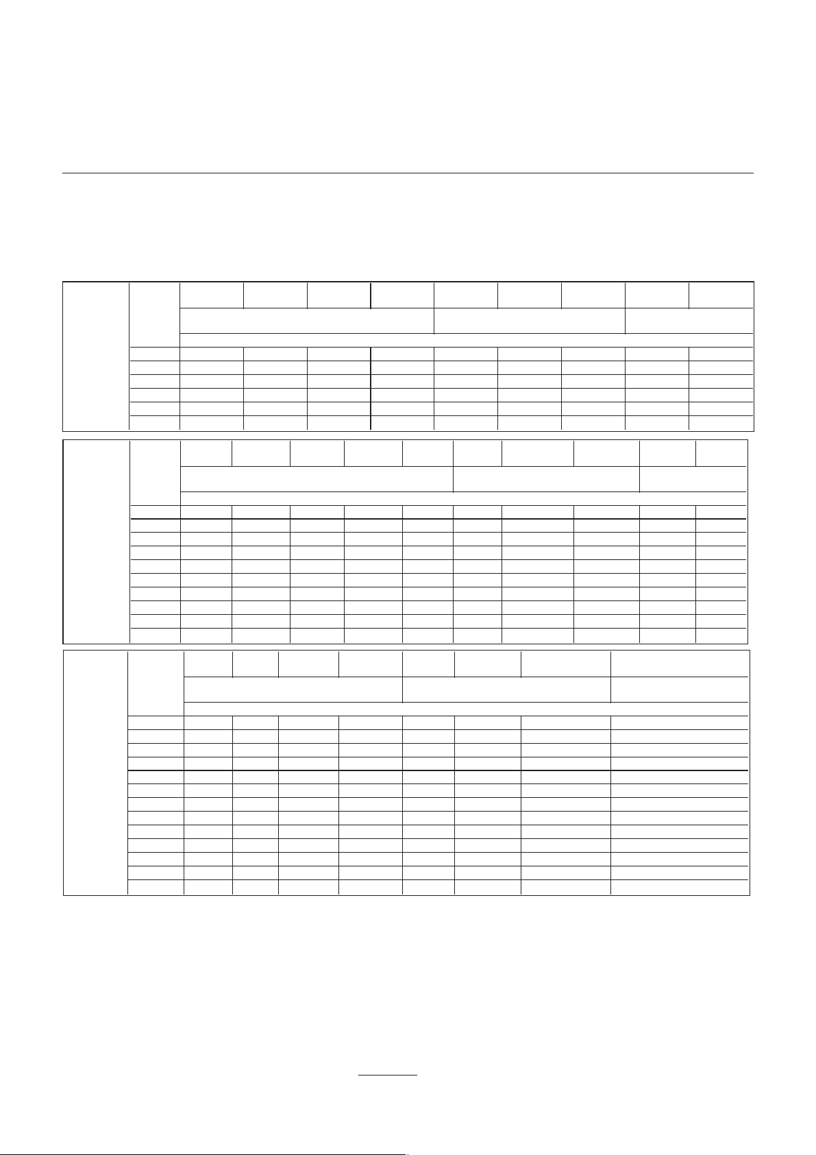
Technische Daten
Arbeitsfelder
VGL 06.1200 DP VGL 06.1600 DP VGL 06.2100 DP
Brennerleistung min.-max. kW 300 - 1200 300 - 1600 480 - 2050
Regelbereich Gas / Öl 1 : 3 / 1 : 2 * 1 : 3 / 1 : 2 * 1 : 3 / 1 : 2 *
Gasfließdruck mbar 20 - 50- 100
Gasarmaturengruppe MBVEF 412 / MBVEF 420 / VGD20 Rp2 / VGD40 DN65 / VGD40 DN80
Brennstoff Erdgas (LL, E) Hi= 8,83 - 10,35 kWh/m3oder Flüssiggas (F) Hi= 25,89 kWh/m
Feuerungsautomat / Flammenwächter LFL 1.333
Brennermotor 2800 min-1, 230 / 400 V, 50 Hz, 2,2 kW
Elektrische Leistungsaufnahme
Betrieb
Schutzart IP54
Zündtransformator EBI-M ; 2 x 7,5kV
Luftklappenstellantrieb SQM 50. 481
Luftdruckwächter LGW 10 A 2
Flammrohr Ø x Eintauchtiefe mm 227 x 270 (KN) / 370 (KM) / 470 (KL)
Gewicht kg insgesamt 130 kg
CE Zeichen 1312 BM 3426 1312 BM 3427 1312 BM 3428
Prüfung nach EN 676 ; Emissionsklasse 3 bei Gasbetrieb
Schalldruckpegel nach VDI2715 dB(A) 78 79 81
Max. Umbgebungstemperatur 60°C
Ölpumpenmotor 0,45 kW; 2800 min
Öldruckpumpe AJ6 CC1004 3P; 290l/h
Schlauchleitungen Zwischen Anlage und Öldruckpumpe: 2 x L1500; M16x1,5 - R1/2
* Das Regelverhältnis ist ein mittlerer Wert und kann je nach Anlagenauslegung variieren.
Heizöl EL nach Ländernormung
2800 min-1, 230 / 400 V, 50 Hz, 2,
2840 W 3380W
nach EN 267 ; Emissionsklasse 1 bei Ölbetrieb
-1
; 230 V
Zwischen Öldruckpumpe und Brennkopf : 1x L1300; M14x1,5 - M14x1,5
3
5 kW
Erläuterung zur Typenbezeichnung:
G = Erdgas
L = Heizöl EL
VGL 06.1200 DP
Arbeitsfelder
Bei der Brennerauswahl ist der Kes
selwirkungsgrad zu berücksichtigen.
Das Arbeitsfeld zeigt die
Brennerleistung in Abhängigkeit vom
Feuerraumdruck. Es entspricht den
Maximalwerten nach EN 676,
gemessen am Prüfflammenrohr.
06 = Baugröße
1200 = Leistungskennziffer
DP = modulierender Betrieb
VGL 06.1600 DP
Berechnung der Brennerleistung:
-
Q
N
QF= x100
η
Q
= Brennerleistung (kW)
F
Q
= Kesselnennleistung (kW)
N
η = Kesselwirkungsgrad (%)
06/2011 - Art. Nr. 13 018 118C
KN = Brennkopflänge normal
KM = Brennkopflänge medium
KL = Brennkopflänge lang
VGL 06.2100 DP
3
Page 4
Übersicht
Gasarmaturenauswahl
Achtung:
Dem in Tabelle angegebenen Druckver
•
lust ist der Feuerraumdruck des Kessels
bei Nennlast in mbar hinzurechnen.
MBVEF
412
Erdgas E Hi = 10,365 kWh/m
Gasdruckverlust (ab Eingang Gasarmatur)
MBVEF
412
Erdgas E Hi = 10,365 kWh/m
Gasdruckverlust (ab Eingang Gasarmatur)
MBVEF
420
Erdgas E Hi = 10,365 kWh/m
Gasdruckverlust (ab Eingang Gasarmatur)
MBVEF
420
VGD20
Rp2
VGL 06.1200
DP
VGL 06.1600
DP
VGL
06.2100 DP
Brennerleistung
(kW)
800 18 15 15 15 21 15 15 15 15
900 23 18 15 15 27 19 15 17 15
950 26 20 15 15 30 21 16 19 15
1000 29 22 16 15 33 23 17 21 15
1100 35 27 19 15 40 28 21 25 15
1200 41 32 23 17 48 33 25 30 15
Brennerleistung
(kW)
800 18 15 15 15 15 21 15 15 15 15
900 23 18 15 15 15 27 19 15 17 15
950 26 20 15 15 15 30 21 16 19 15
1000 29 22 16 15 15 33 23 17 21 15
1100 35 27 19 15 15 40 28 21 25 15
1200 41 32 23 17 15 48 33 25 30 15
1300 - 37 26 20 15 56 39 29 - 17
1400 - 43 31 23 17 65 45 34 - 20
1500 - 50 35 26 20 74 52 39 - 23
1600 - 57 40 30 22 85 59 44 - 26
Brennerleistung
(kW)
1100 23 17 15 15 33 25 15 15
1150 25 18 15 15 36 27 15 15
1200 27 20 15 15 40 29 17 15
1250 30 22 15 15 43 32 18 15
1300 32 23 17 15 47 34 20 15
1400 37 27 19 15 54 40 23 15
1500 43 31 22 16 62 46 26 15
1600 49 35 25 18 71 52 30 17
1700 55 40 28 20 80 59 33 20
1800 62 45 32 22 89 66 37 22
1900 69 50 35 25 100 74 42 25
2000 76 55 39 28 - 82 46 27
2100 84 61 43 30 - 90 51 30
-
MBVEF
420
Der hieraus ermittelte Gasfließdruck ist
•
am Eingang der Gasarmatur einzuhalten.
Für die Ermittlung des an der Übergabe
station erforderlichen Gasfließdrucks ist
zusätzlich der Druckverlust der Gaszulei
tung von Übergabestation bis Eingang
Gasarmatur inkl. aller hier enthaltener
VGD20
Rp2
3
VGD20
Rp2
3
VGD40
DN65
3
VGD40
DN65
VGD40
DN80
VGD40
DN65
MBVEF
420
Erdgas LL Hi = 8,83 kWh/m
VGD40
DN80
MBVEF
420
Erdgas LL Hi = 8,83 kWh/m
Armaturen (Absperrventile, Kompensator,
Gaszähler, TAS, zusätzlicher Filter, etc.)
zu berücksichtigen.
Der Arbeitspunkt der Anlage muss
•
innerhalb des zulässigen Arbeitsfeldes
des Brenners liegen.
VGD20
Rp2
MBVEF
420
Erdgas LL Hi = 8,83 kWh/m
VGD20
Rp2
VGD20
Rp2
VGD40
DN65
3
VGD40
VGD40
DN65
3
DN65
3
MBVEF
412
Flüssiggas
Hi=25,89kWh/m³
MBVEF
412
Flüssiggas
Hi=25,89kWh/m³
MBVEF
420
Flüssiggas
Hi=25,89kWh/m³
MBVEF
420
MBVEF
420
Beispiel : VGL 06.2100 DP
•
Anlagendaten :
–
Gasart : Erdgas E
–
Erforderliche Brennerleistung : 1600 kW
–
Feuerraumdruck bei Kesselnennlast : 3 mbar
–
Gasfließdruck an Übergabestation bei Kesselnennlast : 30 mbar
–
Druckverlust Gaszuleitung bei Kesselnennlast : 1 mbar
•
Ausgewählte Gasarmatur : VGD40.065
•
Prüfung der Auswahl :
–
Gasdruckverlust ab Gasarmatur (aus Tabelle) : 25 mbar
–
Feuerraumdruck : 3 mbar
–
Druckverlust Gaszuleitung 1 mbar
–
Summe 29 mbar
–
Gegeben : Gasfließdruck an Übergabestation : 30 mbar > 29 mbar ðAuswahl VGD40.065 richtig.
4
06/2011 - Art. Nr. 13 018 118C
Page 5
Übersicht
DE
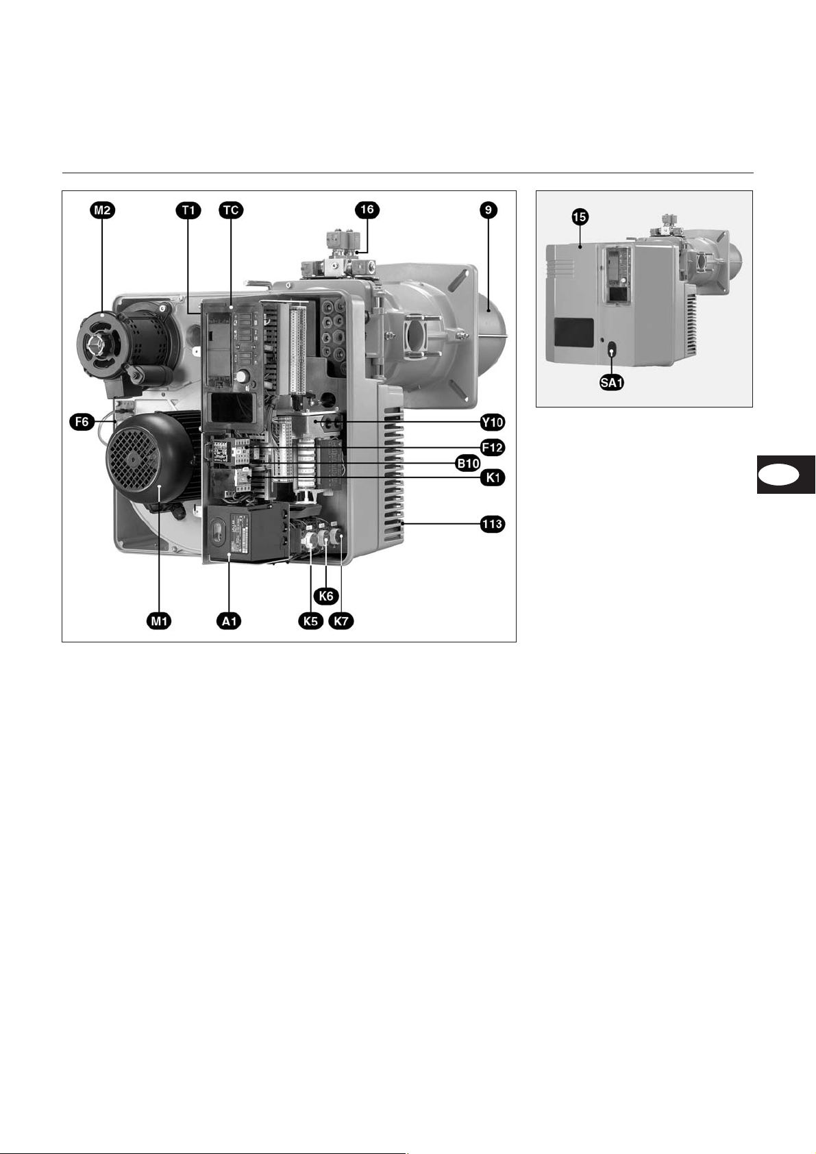
Brennerbeschreibung
A1 Feuerungsautomat
B10 Messbrücke (verdeckt)
F6 Luftdruckwächter
F12 Motorschutzrelais
K1 Motorschutz
M1 Brennermotor
M2 Ölpumpenmotor
SA1 - Entstörtaste
- Programmanzeige
T1 Zündtransformator (verdeckt)
TC Schaltfeld
Y10 Stellantrieb Luftklappe
9 Flammrohr
15 Brennerhaube
16 Ventilblock
113 Luftkasten
06/2011 - Art. Nr. 13 018 118C
5
Page 6
Übersicht
D
E
H
E
H
D
KL
KM
KN
KL
KM
KN
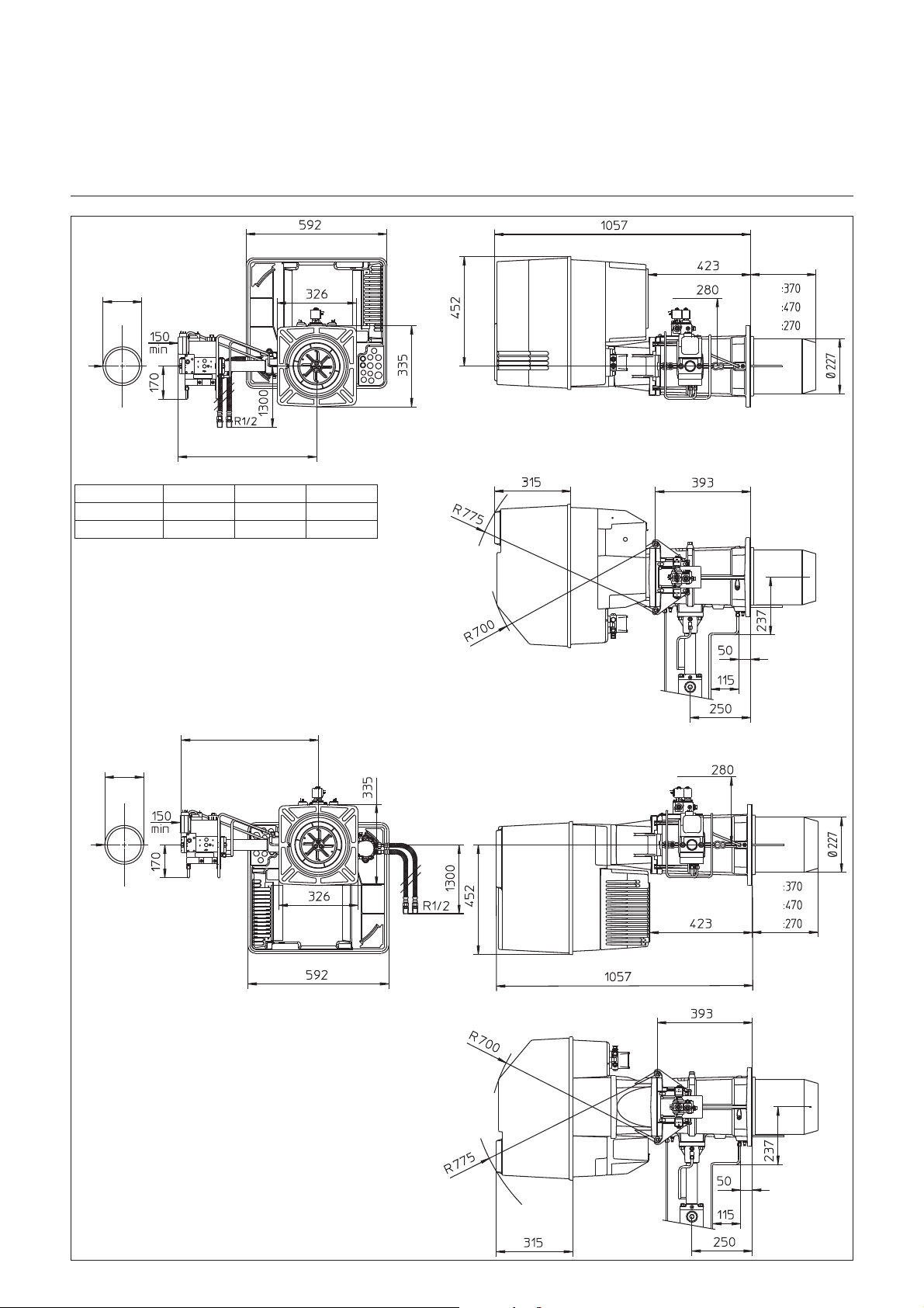
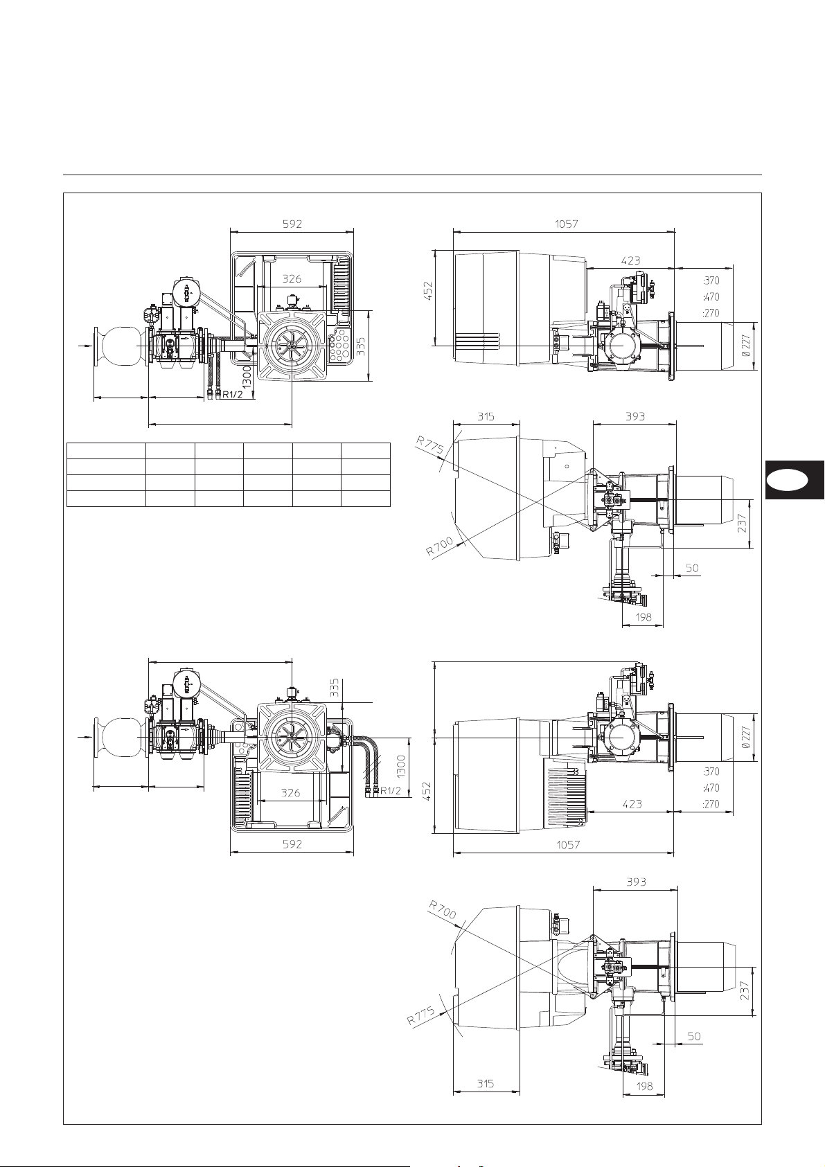
Maßbild und Abmessungen
GL 06.1200/1600/2100 DUO PLUS
mit Gasarmatur MBVEF 412 und MBVEF 420
DEH
MBVEF 412 160 590 Rp2
MBVEF 420 — 690 —
Abstände
Für Servicearbeiten ist ein freier
Abstand von min. 0,8m auf jeder Seite
des Brenners sicherzustellen.
Gasarmaturgruppe
Montage sowohl links als auch rechts
möglich.
6
06/2011 - Art. Nr. 13 018 118C
Page 7
Übersicht
G
DE
F
F
D
E
H
H
KL
KM
KN
KL
KM
KN
DE
Maßbild und Abmessungen
VGL 06.1200/1600/2100 DP
mit Gasarmatur VGD20-Rp2, VGD40-DN65 und VGD40-DN80
DEFGH
VGD20.053 186 292 734 344 Rp2
VGD40.065 290 292 740 365 DN65
VGD40.080 320 312 746 375 DN80
Abstände
Für Servicearbeiten ist ein freier
Abstand von min. 0,8m auf jeder Seite
des Brenners sicherzustellen.
Gasarmaturgruppe
Montage sowohl links als auch rechts
möglich.
06/2011 - Art. Nr. 13 018 118C
7
Page 8

Funktion
NV
Kompaktarmatur MBVEF
Die Gaskompaktarmatur MBVEF ist die
Integration von Filter, Gas / Luftverbun
dregler, Ventilen und Druckwächter.
Feinfilter mit 0,8mm Maschenweite
–
Druckwächter GWA5
–
Servo-Druckregelteil mit einstellba-
–
rem Verhältnis V, Korrektur des Nullpunktes N und
Feuerraumdruckanschluß.
Magnetventile V1, V2 schnellschlie-
–
ßend, schnellöffnend
Eingangsdruck pe : 20-100mbar
Spannung, Frequenz : 230V, 50-60Hz.
-
1 Elektroanschluß des
Gasdruckwächters (DIN 43650)
2 Elektroanschluß der Magnetventile
(DIN 43650)
3 Gasdruckwächter
4 Eingangsflansch
5 Druckmeßnippel R1/8,
vor Filter (beidseitig)
6 Filter (unter Deckel)
7 Typenschild
8 Anschluß Luftdruckleitung pL,
R 1/8
9 Einstellschraube für Verhältnis V
10 Druckmeßnippel pe, vor Ventil 1,
beidseitig
11 Gasdruckmeßnippel M4 nach
Ventil 2
12 Einstellschraube Nullstellung N
13 Anschluß Feuerraumdruckleitung
pF, R1/8
14 Anschluß Gasdruckleitung pG,
R1/8
15 Ausgangsflansch
16 Druckmeßnippel pa nach
Ventil1, beidseitig
17 Betriebsanzeige Ventile V1, V2
18 Impulsleitungen
Brenner VGL 06.1600/2100 DP
Gas: Druck ("-e)
E-Gas: 20, 25
LL-Gas: 20, 25
E-Gas : 100
LL-Gas: 100
F-Gas : 37
F-Gas : 50
Fettgedruckt : Werkslieferung
VEF
V
N
V
N
V
N
V
N
412 420
1,25
1,25
0
1,25
0
1,25
0
Gasdruckwächtereinstellung
•
Durchsichtigen Deckel ablegen. Die
Einstellung erfolgt über eine
Verstellscheibe mit Kreisskala und
Index x.
•
Provisorisch auf den minimalen Ska
-
lenwert einstellen.
0
8
06/2011 - Art. Nr. 13 018 118C
Page 9

Funktion
DE
Gasarmatur VGD mit SKP 75 Regler
1 Elektroanschluß des
Gasdruckwächters (DIN 43650)
2 Elektroanschluß der Magnetventile
(DIN 43650)
3 Gasdruckwächter
4 Eingangsflansch
5 Druckmeßnippel R1/8, vor Filter
6 Filter (unter Deckel)
7 Typenschild
8 Anschluß Luftdruckleitung pL,
R 1/8 (verdeckt)
9 Einstellschraube für Verhältnis V
12 Einstellschraube Nullstellung N
13 Anschluß Feuerraumdrucklei
-
tung pF, R1/8
14 Anschluß Gasdruckleitung pG,
R1/8
15 Ausgangsflansch
16 Impulsleitungen PBr, pL, pF
Gasdruckwächtereinstellung
•
Durchsichtigen Deckel ablegen. Die
Einstellung erfolgt über eine Verstell
scheibe mit Kreisskala und Index.
•
Provisorisch auf den minimalen Ska
lenwert einstellen.
pBr (pG)=Impulsleitung Gas
pF = Impulsleitung Feuerraum
pL = Impulsleitung Luft
Der SKP-Regler kombiniert mit einem
VGD Ventil sichert ein konstantes Verhältnis zwischen Gas- und Luftdurchsatz mit einstellbarem Verhältnis
D = Einstellschraube (Luftüberschuß)
R = Einstellschraube (Verhältnis
Gas/Luft)
-
-
Einstell-Index
des D-Wertes
Brenner VGL 06.1200 DP
Gas:Druck ("-e)
E-Gas: 20, 25
LL-Gas: 20, 25
Brenner GL 06.1600/2100 DUO PLUS
Gas:Druck ("-e)
E-Gas: 20, 25
LL-Gas: 20, 25
Fettgedruckt : Werkslieferung
(Schr. R) 1,4 1,3
(Schr. D) 22
(Sc. R) 1,3 1,3
(Sc. D) 20
VGD
Rp2
VGD
DN65
DN65
DN80
VGD
VGD
06/2011 - Art. Nr. 13 018 118C
Einstell-Index
des
Verhältnisses“
R ”
Anzeige der
Gasventilöffnung
9
Page 10
Funktion
Ölversorgung
Ölversorgung
Zur Gewährleistung der Betriebssicher
heit der Anlage ist die sorgfältige Instal
lation der Ölversorgung nach DIN 4755,
sowie unter Beachtung örtlicher Vor
schriften erforderlich. Der Brenner ist
mit einer selbstansaugenden Zahnrad
pumpe ausgestattet, die als
Zweistrangpumpe über einen Ölfilter
angeschlossen werden muss.
Beachten :
Max. Zulaufdruck an der Pumpe
•
< 2bar.
Max. Ansaugvakuum an der Pumpe
•
< 0,4bar
Typ
VGL
06.1200 DP
Brennerleistung
kW kg/h 1. Stufe 2. Stufe 3. Stufe 1 2 3
700
900
1100
1200
Öldurch
- satz
60
76
93
102
Düse Danfoss
(1)US gal/h
45° B oder 60° B
7,5
7,5
8,5
8,5
Zur Projektierung und Dimensionierung
von Anlagen mit Sauginstallation für
Heizöl EL ist die ELCO Broschüre
Art.-Nr: 12002182 unbedingt zu
beachten.
-
Ölpumpe anschließen und durch die
Mitgelieferte Ölschläuche an der
•
Öffnung des Gehäuses führen.
Ölfilter mit Entlüftungsmöglichkeit
•
(empfohlene Maschenweite : 70 µm)
so platzieren, dass ein knickfreier
und zugentlasteter Anschluss der
Ölschläuche gewährleistet ist.
Richtigen Anschluss von Vor- und
•
Rücklauf beachten.
Pumpendruck
bar
3,75
5
7,5
7,5
3,75
5
7,5
7,5
12,5
15,5
14,0
15,5
12,0
15,5
13,5
13
12,0
15,5
13,0
14,5
Vor Inbetriebnahme Öl mit
Handpumpe ansaugen und
m
Dichtheit der Ölleitungen
überprüfen.
AJ6 CC1004 3P
700
VGL
06.1600 DP
VGL
06.2100 DP
Bei Auslieferung ist die Pumpe auf 13,5 bar ± 0,5 bar eingestellt. Fettgedruckt : Ausrüstungszustand bei Lieferung
1kg Heizöl bei 10°C = 11,86 kW (1) Gleichwertige Düsen : Steinen 60°SS - Hago 60P, 45P
900
1100
1300
1600
1150
1400
1700
1900
2050
60
76
93
110
135
97
118
142
160
173
7,5
7,5
8,5
11
11
11
11
13,5
12
13,5
3,75
5
7,5
7,5
11
8,5
10
11
12
13,5
3,75
5
7,5
7,5
11
8,5
10
11
12
13,5
12,5
15,5
14,0
14
14
10,5
14,5
13,5
15,5
16
12,0
15,5
13,5
14
14
10,0
14,0
12,0
15,0
15,0
12,0
15,0
13,0
13,5
13,5
10,0
13,5
11,5
14,0
14,0
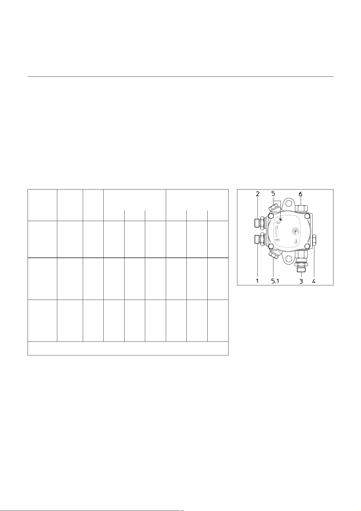
Zeichenerklärung
1 Sauganschluss M16x1,5
2 Rücklaufanschluss M16x1,5
3 Düsenausgang M14x1,5
4 Manometeranschluss G1/8
5 Vakuummeteranschluss oder
Zulaufdruck (für Vakuummeter
oder Manometer) G1/8
6 Öldruckregler
Öldruckregulierung
Der Öldruck und damit die Brennerlei
-
stung wird mit dem Öldruckregler 6 ein
gestellt. Drehen nach
–
rechts : Druckerhöhung
–
links : Druckreduzierung.
Zur Kontrolle muß am Manometeran
-
schluß 4 ein Manometer angesetzt
werden, Gewinde R1/8.
Unterdruckkontrolle
Das Vakuummeter für die Unterdruc
kkontrolle ist am Anschluß 5 anzu
-
schliessen, G1/8. Höchstzulässiger
Unterdruck 0,4bar. Bei höherem Unter
druck vergast das Heizöl, wodurch
kratzende Geräusche in der Pumpe
entstehen
-
-
10
06/2011 - Art. Nr. 13 018 118C
Page 11
Funktion
DE
Schaltfeld TC
Schaltfeld
Alle Steuerorgane sind von außen
sichtbar. Ein ablegbarer, durchsichtiger
Deckel, auf die Haube geklipst, ermög
licht den Zugang zu den Steuer- und
Kontrollorganen für Einstellung und
Betrieb des Brenners.
Das Schaltfeld beinhaltet auch zwei
grüne Dioden, die den benutzten
Brennstoff angeben, sowie die
Sicherung des Schaltkreises.
Um den Deckel abzulegen, ein- oder
beidseitig an den mit xvmarkierten
Stellen leicht eindrücken und gleichzei
tig herausziehen.
Um den Deckel wieder aufzusetzen,
beide Klipse vor die entsprechenden
Öffnungen stellen und eindrücken.
HINWEIS:
Für die Inbetriebnahme besteht die
Möglichkeit, bei Gasbetrieb, neben den
-
Endlagen min. Last und max. Last,
auch Teillastpunkte anzufahren.
Hierzu ist die 4 polige Steckverbindung
(Ansteuerung der Laststufen) zum
Kessel zu trennen.
Mit dem Schalter S3 kann die Laufrich
tung + oder - gewählt werden.
Ist der Schalter S2 auf Position"Hand"
läuft der Stellantrieb in die Endlage.
Wird der Schalter S2 auf “Auto” gestellt,
stoppt der Stellantrieb auch in Zwi
schenlagen.
-
Option :
–
Dreipunktschrittregler RWF 40 in
genormter Einbaustelle.
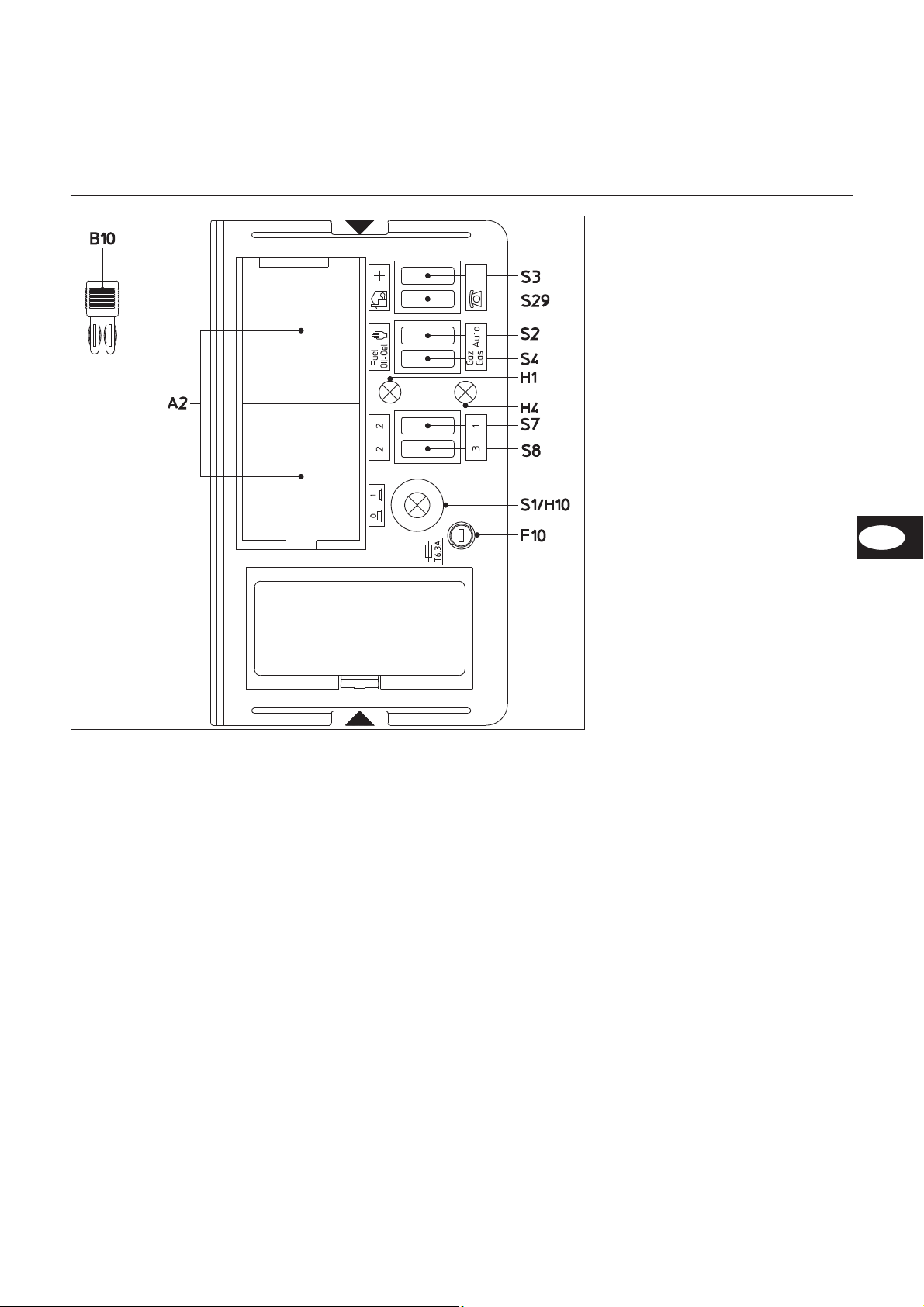
Funktion
A2 Genormte Einbaustellen 48x48
oder 48x96 mm für den Einbau
eines Leistungsreglers (Option)
B10 Messbrücke [µA DC] für Zellen
strom, Anordnung neben dem
Motorschütz
F10 Sicherung
H1 Signallampe Ölbetrieb
H4 Signallampe Gasbetrieb
S1 Hauptschalter
0 Aus
1 Ein,
grüne Kontroll-Lampe H10
leuchtet
S2 Wahl der Leistungsregelung
K Handbetrieb
Auto Vorort-Automatikbetrieb
S3 Steht in Verbindung mit
S29J - S2K
+/- Leistungszunahme/-Abnahme
S4 Brennstoffwahlschalter Öl / Gas
Steht in Verbindung mit
S29J - S2K
S7-S8 Steht in Verbindung mit
S29J - S2K
S7.1+S.8.2 1. Stufe Öl
S7.2+S.8.2 2. Stufe Öl
S7.2+S.8.3 3. Stufe Öl
S7.1+S.8.3 3. Stufe Öl
S29 Wahlschalter des Betriebsorts
J Vorortbetrieb
H Fernbetrieb (option)
SA1 Anzeige Feuerungsautomat
Entstörtaste - Störlampe
-
-
(Anordnung auf Feuerungsauto
mat)
Achtung :
m
Hauptschalter des Schaltfeldes schaltet
nur Steuerspannung. Vor Arbeiten im
Schaltteil des Brenners, diesen
komplett, incl. Drehstromanschluß Bren
nermotor, vom Netz trennen.
-
-
-
06/2011 - Art. Nr. 13 018 118C
11
Page 12
Funktion
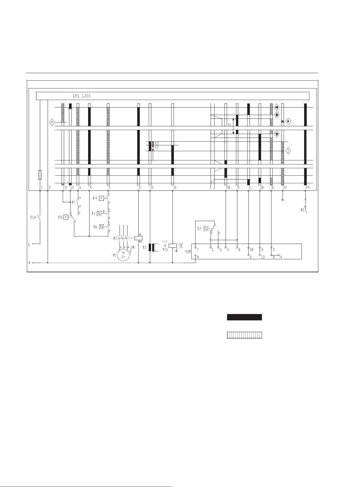
Feuerungsautomat LFL 1.333 / Funktionsbeschreibung
Funktionsbeschreibung
–
Regelthermostat fordert Wärme an.
–
Das Steuerprogramm des Steuerge
rätes läuft an, wenn der Luftdruc
kwächterkontakt in Ruhestellung ist,
vom Gadruckwächter ausreichend
Gasdruck gemeldet wird und Luft
klappe in “ZU”-Stellung (Nocke II)
–
Brennermotor läuft an
–
Luftklappe öffnet auf Volllaststellung
(Nocke I)
–
Vorbelüftungszeit ca. 30 sec.
Während der Vorspülzeit wird
–
der Gebläsedruck überwacht
–
der Feuerraum auf Flammensignale
überwacht.
Brennstoffvorwahl Gas
Nach Ablauf der Vorspülzeit wird
–
die Luftklappe in Zündstellung Gas
gefahren (Nocke III)
–
wird die Zündung zugeschaltet
–
wird das Haupt- und Sicherheits
magnetventil geöffnet.
–
Brennerstart
–
Regelfreigabe nach Ablauf der
Sicherheitszeit
–
Öffnung der Luftklappe auf “Kleinlast
Gas” (Nocke V)
–
Beginn des Regelbetriebes
–
max. Last Gas wird bei Nockenposi
tie I erreicht
Brennstoffvorwahl Öl
Nach Ablauf der Vorspülzeit wird
–
die Luftklappe in Zündstellung Öl
-
-
-
gefahren (Nocke IV)
–
wird die Zündung zugeschaltet
–
Magnetventil Y1 Stufe 1 geöffnet
–
Brennerstart in Stufe 1
t1 Vorbelüftungszeit 30s
t2 erste Sicherheitszeit 3s
t3 Vorzündzeit 6s
- Sicherheitszeit bei Verschwinden
des Flammensignals < 1s
Befehle zum
Feuerungsautomaten.
Umschalten auf Öl Stufe 2
Bei Anforderung der Leistungsstufe 2
wird
–
die Luftklappe auf 2. Stufe Stellung
notwendige
Eingangssignale.
(Nocke VI) gefahren
–
bei Position Nocke VII Magnetventil
Y2 geöffnet, Brenner brennt mit zwei
Düsen
Umschalten auf Öl Stufe 3
–
Luftklappe auf Stufe 3 (Nocke I)
–
bei Position Nocke VII wird Magnet
-
ventil 3 Stufe geöffnet
-
-
12
06/2011 - Art. Nr. 13 018 118C
Page 13
Montage
5
4
6
DE
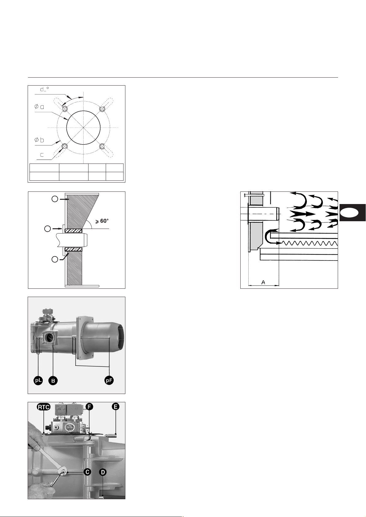
Brennermontage
Ø a (mm) Ø b (mm) c d
250
300 bis 400
M12 45°
Montage Brennkopf
Brennerplatte/Kesseltüre gemäß
•
nebenstehender Zeichnung vorberei
ten.
Innendurchmesser a Ø 250 mm
•
festlegen.
Für die Brennkopfflanschbefestigung
•
sind 4 Bohrungen M12 (Lochkreis
durchmesser 300-400 mm) gemäß
nebenstehender Zeichnung erforder
lich.
Stehbolzen M12 in die Brenner
•
platte/Kesseltüre einschrauben und
die Isolationsunterlage aufsetzen.
Bei Lochkreis <400 mm vorge
stanzte Langlöcher auf das erforder
Brennerrohr-Einbautiefe und Aus
mauerung
Bei Wärmeerzeugern ohne gekühlte
Vorderwand ist, sofern der Kesselher
steller keine andere Angaben macht,
eine Ausmauerung 5 wie im nebenste
henden Bild erforderlich. Die Ausmauerung darf die Flammrohrvorderkante
nicht überragen und mit maximal 60°
konisch zulaufen. Der Luftspalt zwischen
Ausmauerung und Brennerrohr ist mit
einem elastischen, nicht brennbarem
Isolationsmaterial 6 auszufüllen. Bei
Kesseln mit Umkehrfeuerung ist die
minimale Eintauchtiefe A des Brennerrohres gemäß Angaben des Kesselherstellers zu beachten.
-
-
-
-
-
liche Maß ausschneiden.
Brennkopf mit 4 Sechskantmuttern
•
M12 befestigen.
Der Raum zwischen Flammrohr und
•
Türisolierung ist mit feuerfestem
Material auszukleiden
Achtung:
die Feuerraumdruckabnahmeleitung
pF darf nicht verstopft werden.
-
-
-
Montage Brennergehäuse
Hängt das Brennergehäuse unter der
Brennkopfachse, ist wie folgt vorzuge
hen.
•
Brennergehäuse auf Brennkopf
mittels fester (gegenüber dem Gas
anschluß) Achse F befestigen.
•
Die zwei Zündkabel anschließen.
•
Brenner mit Achse E schließen.
•
Sicherungsschraube D anziehen.
Falls erforderlich kann das Gehäuse
über die Brennerkopfachse montiert
werden.
Andere Brennergehäusestellungen sind
nicht möglich.
•
Anschließen der Ölschlauche zum
Ölfilter.
•
Anschließen der Öldruckleitung von
der Pumpe zum Ölmagnetventil
block.
•
Ölschlauchverbindungen auf
Dichtheit prüfen.
•
Elektrische Steckverbindung
zwischen Hydraulikblock und
Brenner herstellen.
-
-
-
06/2011 - Art. Nr. 13 018 118C
13
Page 14
Montage
1
2
3 4
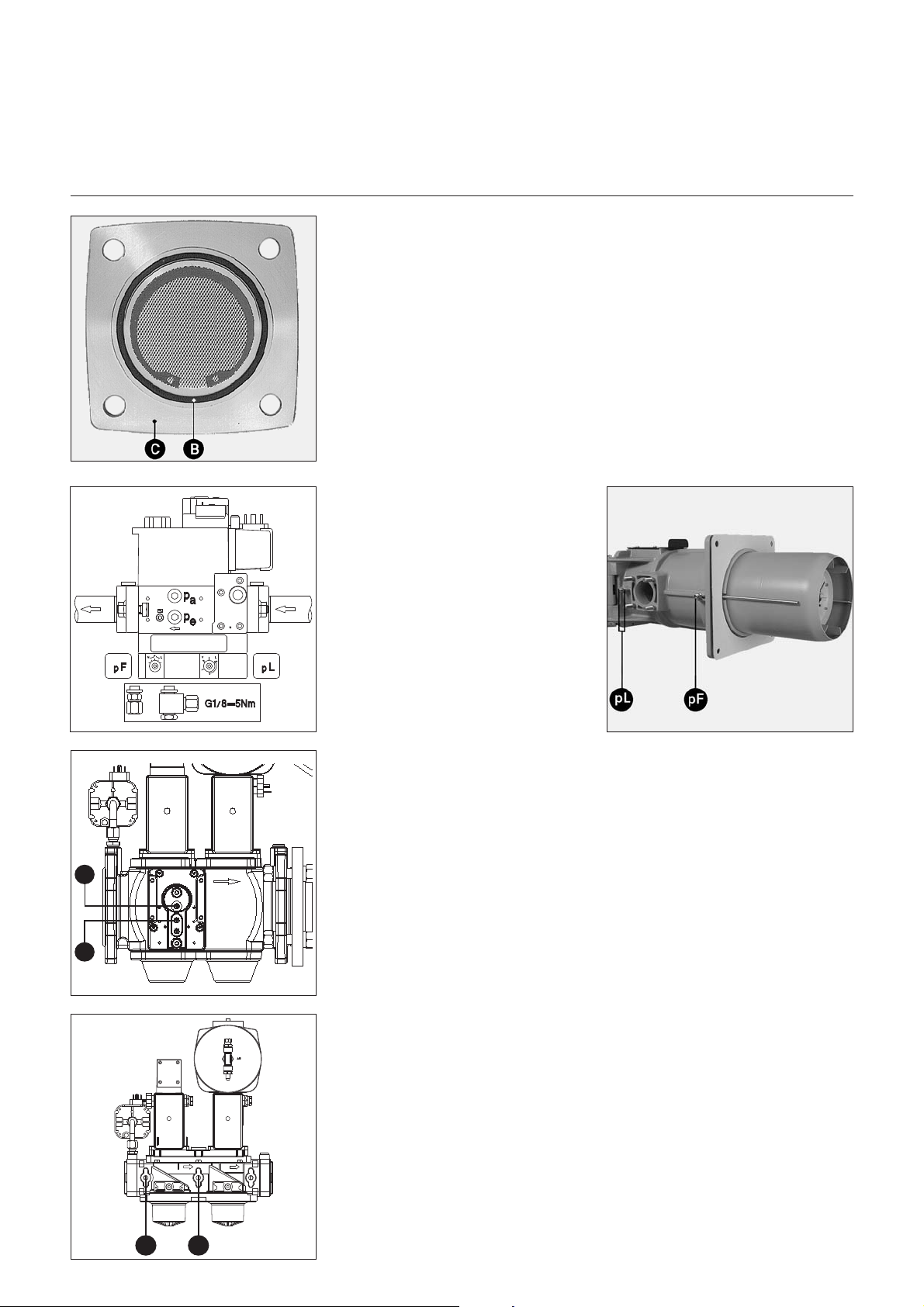
Gasarmaturmontage
Dichtheitskontrollgerät VPS 504 S01
Montage Gasarmatur VGD/MBVEF
Die richtige Einbaulage des
•
O-Ringes B im Gasanschlußflansch
C überprüfen.
Die Gasarmatur mit Muttern M10 so
•
befestigen, daß der SKP-Regler
oder die Magnetspulen der MBVEF
unbedingt senkrecht über der Gas
armatur liegen.
Die mitgelieferten, gekennzeichneten
•
Impulsleitungen pF, pL und pG für
linken oder rechten Gasanschluß
montieren.
Anschluß der Druckabnahmeleitungen
Die zwei Stopfen pF und PL auf
•
dem Zwischenrohr abnehmen.
Die zwei verbundenen Rohrverbin
•
der mit einem zugelassenen Dich
tungsmittel auf den
Gasdruckleitungen pF und pL
montieren.
• Die Verbindungen zwischen Ventil
und Zwischenrohr für eine rechts
liegende Gasarmatur mit den
Leitungen pF und pL, für eine links
eingebaute Gasarmatur mit den pF
und pL “links” bezeichneten
Leitungen herstellen.
• Später auf Dichtheit prüfen.
Bei VGD Ventilen Antrieben stehend
•
nach oben montieren, den mitgelie
ferten Gasfilter (Bausatz) waage
recht mit obenliegendem Deckel (2
Messanschlüsse) einbauen.
Fließrichtung beachten.
•
Ein thermisch auslösendes Sicher
•
heitsventil und einen Gaskugelhahn
-
(bauseits) vor der Gasarmatur
montieren.
-
-
-
-
-
Einbau des Dichtheitskontrollgeräts
VPS 504 S02 auf MBVEF/VGD40
•
Die zwei Schrauben pa und pe auf
Ventil MBVEF, auf Ventil VGD40 die
Schraube 1 und 2.
•
Darauf achten, daß die zwei
O-Ringe auf dem Dichtheitskontroll
gerät vorhanden sind.
•
Das Gerät VPS504 mit den vier mit
gelieferten selbstschneidenden
Schrauben befestigen.
•
Elektrische Verbindung mittels 7P
Stecker herstellen.
•
Auf Dichtheit prüfen.
Einbau des Dichtheitskontrollgeräts
VPS 504 S02 auf VGD20 :
•
Die zwei Schrauben 3 und 4
entfernen.
•
Doppelnippel einschrauben.
•
Verrohrungsset und Anschlußadap
ter montieren.
•
VPS504 und Anschlußadapter mit
den vier mitgelieferten selbstschnei
denden Schrauben befestigen.
•
Darauf achten, daß die zwei O-Ringe
auf dem Dichtheitskontrollgerät
vorhanden sind.
•
Elektrische Verbindung mittels 7P
Stecker herstellen.
•
Auf Dichtheit prüfen.
-
-
-
-
14
06/2011 - Art. Nr. 13 018 118C
Page 15
Montage
4
5
5
5
5
DE
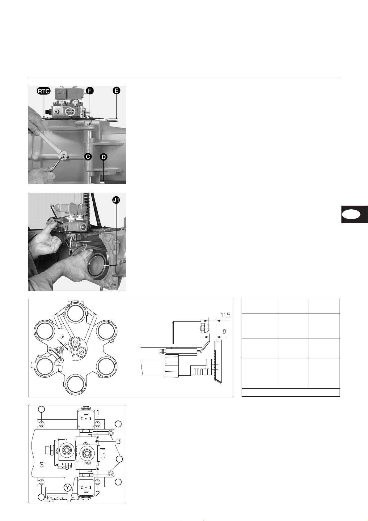
Prüfungen und Einstellungen
Mischeinrichtung und Sekundärluft
Prüfungen und Einstellungen der
Mischeinrichtung
Bei Lieferung ist der Brenner für einen
Betrieb mit Erdgas eingestellt.
Sicherungsschraube D entfernen.
•
Den beweglichen Achsbolzen E
•
entfernen.
Brennergehäuse öffnen.
•
Die zwei Zündkabel trennen.
•
Schlauch auf dem Ölverteiler
•
entfernen.
Die vier Schrauben 5 der Platte
•
RTC um zwei Umdrehungen lösen.
Die Mutter und seitliche Schraube C
•
lösen, die zur Befestigung der Gasund Ölzufuhrleitung dienen.
Die Mischeinrichtung herausnehmen.
•
Folgende Einstellungen überprüfen :
•
Zündelektroden und Gasdüsen ent
sprechend dem verfügbaren Gas
und den beigefügten Zeichnung.
Die Brennerdüsen entsprechend der
•
Kesselleistung einbauen.
• Vorhandensein und ordnungsgemä-
ßen Sitz des O-Ringes J1 auf dem
Gaskopf überprüfen.
• In umgekehrten Reihenfolge wieder
einbauen.
• Zu prüfen :
– festen Sitz der Schraube und
Mutter C prüfen.
– später auf Dichtheit prüfen.
(Öl- und Gasseite)
Sekundärluft
Es handelt sich um das zwischen dem
Durchmesser der Stauscheibe und dem
Flammrohr zugeführte Luftvolumen. Die
Stellung der Stauscheibe (Maß Y) ist
auf einer Skala des RTC-Systems
(Erhaltung der Brennkopfeinstellung)
von 0 bis 50 mm abzulesen, wobei 50
mm der größten und 0 der kleinsten
Sekundärluftzufuhr entspricht. Bei
Lieferung des Gerätes liegt die Einstel
lung des Maßes Y bei 20 bzw. 30 mm
(siehe Tabelle).
In Abhängigkeit von :
Zündqualität (Stöße, Schwingungen),
–
Verbrennungshygiene
–
läßt sich dieser Wert jedoch nachre
–
gulieren.
-
Einstellung
Sie wird ohne Ausbau des Brenners
während Betrieb oder Stillstand ent
sprechend den angegebenen Werten
vorgenommen.
Bei Verringerung des Maßes Y, nimmt
der CO
-Wert zu und umgekehrt.
2
• Die zwei Schrauben 4 (Zeichnung)
lösen.
• Insgesamt in die gewünschte
Richtung verschieben.
• Die zwei Schrauben 4 (Zeichnung)
wieder festziehen.
-
-
-
Typ
VGL
06.1200/1600
DP
VGL 06.1600
DP
VGL 06.2100
DP
Fettgedruckt : Ausrüstungszustand bei Lieferung
Brennerleistung kW
700
900
1100
1200
1100
1300
1600
1150
1400
1700
1900
2050
Maß Y
mm
0
10
20
25
20
30
50
10
20
30
40
50
Die Funktion der einzelnen Ventile ist
auf dem Verteilergehäuse eingraviert,
und zwar : S, 1, 2, 3.
Die elektrischen Steckverbinder sind mit
VS, S1, S2 bzw. S3 gekennzeichnet.
S+VS = Y17 Sicherheitsventil
1+S1 = Y1 Ventil 1. Brennstufe
2+S2 = Y2 Ventil für 2. Brennstufe
3+S3 = Y3 Ventil für 3. Brennstufe.
5 Vier Schrauben zum Heraus-
nehmen der Mischeinrichtung.
4 Zwei Schrauben zum Einstellung
des Maßes Y.
L Sekundärluftwert.
06/2011 - Art. Nr. 13 018 118C
15
Page 16
Montage
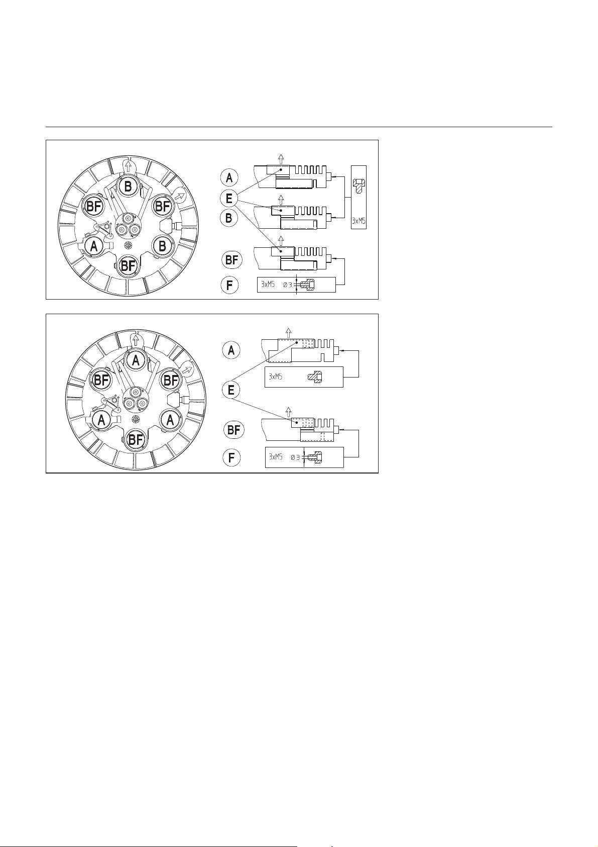
Einstellungen
Gasdüsen
Erdgas
Propangas
Werkseinstellung
5 nach außen offene Schlitze (Pfeil) + 1
Schlitz nach innen an 1 mit A bezeichne
ter Gasdüse gemäß Stellung der Schie
behülse E.
Befestigung der Stauscheibe mit drei
nicht gebohrten Schrauben M5x6 auf
den drei Gasdüsen A und B.
5 nach außen offene Schlitze (Pfeil) +
kein (0) Schlitz nach innen an 5 mit B
und BF bezeichneten Gasdüsen gemäß
Stellung der Schiebehülse E.
Befestigung der Stauscheibe mit drei auf
Ø3 gebohrten Schrauben F M5x6 auf
den drei Gasdüsen BF.
Empfohlene Einstellung
3 nach außen offene Schlitze (Pfeil) + 1
Schlitz nach innen an 3 mit A bezeichne
ten Gasdüsen gemäß Stellung der
Schiebehülse E.
Befestigung der Stauscheibe mit drei
nicht gebohrten Schrauben M5x6 auf
den drei Gasdüsen A.
3 nach außen offene Schlitze (Pfeil) +
kein (0) Schlitz nach innen an 3 mit BF
bezeichneten Gasdüsen gemäß
Stellung der Schiebehülse E.
Befestigung der Stauscheibe mit drei
gebohrten Schrauben F M5x6 auf den
drei Gasdüsen BF.
-
-
-
16
06/2011 - Art. Nr. 13 018 118C
Page 17

Montage
DE
Ölversorgung
Gasversorgung
Elektrische Versorgung
Ölversorgung
Die verwendete Ölbrennerpumpe ist
•
eine selbstansaugende Zahnrad
pumpe, die als Zweistrangpumpe über
einen Entlüftungsfilter angeschlossen
werden muß.
Zur Projektierung und Dimensionierung
•
von Anlagen mit Sauginstallation für
Heizöl EL ist die VSO-Richtlinie
(s. Elco-Klöckner Broschüre
Art.-Nr122887) unbedingt zu beachten.
Mitgelieferte Ölschläuche an der
•
Ölpumpe anschließen (Ölschläuche
können je nach Bedarf durch die
obere bzw. untere Öffnung des
Gehäuses geführt werden).
Allgemeine Vorschriften für die Gas
versorgung
Der Anschluß der Gasarmatur an
•
das Gasnetz darf nur von einer
anerkannten Fachkraft durchgeführt
werden.
• Der Gasleitungsquerschnitt muß so
gestaltet werden, daß der vorgeschriebene Gasfließdruck nicht
unterschritten wird.
Bei der Inbetriebnahme des Brenners
wird gleichzeitig die Anlage unter der
Verantwortung des Installateurs oder
seines Stellvertreters abgenommen.
Er allein kann gewährleisten, daß die
-
Die Installation der Ölschläuche ist so
•
festzulegen, daß die Demontage des
Brenners ohne Lösen der Schlauch
leitungen erfolgen kann.
Die Verbindung der Ölschläuche mit
•
dem Ölfilter erfolgt über Anschluß
R3/8" bzw. R1/2" (Doppelnippel für
R3/8"/R1/2" liegen bei).
Die Saugleitung wird bei kubischen
•
Tanks bis 5cm und bei zylindrischen
bis 10cm über Tankboden geführt.
Anlage den geltenden Normen und
-
Vorschriften entspricht.
Der Installateur muß im Besitz einer
vom Gaswerk ausgestellten Zulassung
sein und die Anlage auf Dichtheit
geprüft und entlüftet haben.
-
Elektrische Versorgung
Für den Anschluß des Brenners und
der Regelung ist der entsprechende
Stromlaufplan obligatorisch.
Die Stromversorgung und die elektri
schen Anschlüsse müssen den
geltenden Normen entsprechen.
Der Brenner wird für eine Netzspan
nung von 400V-50Hz Drehstrom mit
Nulleiter und Erdung geliefert.
Sämtliche Steuerleitungen sind mit
5/7-poligen Buchsenteilen versehen.
Prüfung vor Inbetriebnahme
•
Brenner vom Stromnetz trennen und
spannungsfrei machen.
•
Öl- und Gasventile schließen
•
Betriebsvorschriften der Wärmeer
zeuger und Regelunghersteller zur
Kenntnis nehmen.
•
Prüfen ob Gasart, Gasdruck dem
Brenner entsprechen.
•
Dichtheit der Gasleitung.
•
Entlüftung der brennstofführenden
Leitungen.
Das Anschlußkabel für den Brennermo
tor muß durch die Kabelverschraubun
gen geführt und an der Klemmleiste
gemäß Elektroschema verdrahtet
werden. Die elektrische Verbindung
zwischen Brenner, Gasarmatur und
Hydraulikblock erfolgt über die vorgese
-
henen Stecker.
•
Prüfen ob die Frischluftzufuhr und
die Abgaswege mit der Brennerlei
stung übereinstimmen.
•
Wasserdruck im Heizkreis,
•
Umwälzpumpen in Betrieb,
•
Mischer öffnet,
•
Zugregler im Kamin öffnet,
•
Stromversorgung in Ordnung,
•
Ölstand im Tank,
•
Anschlüsse der Ölschläuche
(Vorlauf/Rücklauf) richtig,
•
Dichtheit aller Verbindungsteilen der
Ölleitung vom Brenner bis zum
Tank,
•
Einstellung der Thermostate,
-
-
-
-
•
-
Drehrichtung Gebläsemotor
(siehe Pfeil am Brennergehäuse),
06/2011 - Art. Nr. 13 018 118C
17
Page 18

Inbetriebnahme
10
Luftregulierung
1 Stellindex der Nocken
2 Acht einstellbare Nocken
3 Scheibe mit Skala ;
gibt Stellung der Luftklappe an
4 Anschlußleiste
5 Schlüssel zur Nockeneinstellung
6 Stellantriebkennzeichnung
C Knopf zur Entkupplung der
Nockentrommel (mit Vorsteckstift)
Nicht betätigen!
m
A Skala (0° bis 90°) gibt Stellung
des Stellantriebs an
B Kupplung zwischen Luftklappe
und Stellantrieb
C Stellindex der Luftklappe
Kontrolle der Luftklappenstellung
Die Luftklappenstellung kann an der
Skala A des Luftklappenstellantriebes
abgelesen werden.
Bei Über-Kopf-Montage des Brenners
kann die Luftklappenstellung an der
Skalenscheibe 2 abgelesen werden.
Stellantrieb
Die Verstellung der Luftklappe erfolgt
über einen elektrischen Stellantrieb Typ
SQM50 / 481 A2.
Über die acht Nocken des Stellantrie
bes kann die Stellung der Luftklappe zu
den einzelnen Betriebspunkten des
Brenners justiert werden.
Bei Gasbetrieb ist eine stufenlose
Regelung der Verbrennungsluftmenge
in Verbindung mit einem Dreipunkt
-
schrittregler möglich.
Typ
3 Stuf.
Zweistoff
VGL 06.1200
VGL 06.1600
VGL 06.1600
VGL 06.2100
Fettgedruckt : Ausrüstungszustand bei Lieferung
Brenner
leistung
kW
700
900
1100
1200
1100
1300
1600
1150
1400
1700
1900
2050
Nockeneinstellung in °
I II III IV V VI VII VIII
40
50
55
60
55
70
90
52
65
80
100
100
0
0
0
0
0
0
0
0
0
0
0
0
18
Funktion der Nocken
Nocke Funktion
I Luftkl. / Vollast Öl und Gas
II Luftkl. / Luftabschluss
III Luftkl. / Zündlast Gas
IV Luftkl. / Zündlast u. 1. Stufe Öl
V Luftkl. Gas min.
VI Luftkl. / 2. Stufe Öl
VII Ölventil / 2 Stufe
VIII Ölventil / 3 Stufe
10
10
10
10
10
10
10
10
10
10
10
10
20
22
25
28
25
30
30
25
25
35
35
40
20
20
20
20
20
20
20
20
20
20
20
20
30
37
40
40
40
45
50
42
45
55
55
60
06/2011 - Art. Nr. 13 018 118C
25
30
35
35
35
35
40
30
40
47
48
50
35
45
50
50
50
60
75
47
60
70
70
75
Einstellung
•
Nocken von Hand oder mit beilie
gendem Schlüssel entsprechend der
gewünschten Brennerleistung und
den in der Einstelltabelle angegebe
nen Werten voreinstellen.
Folgende Einstellbeziehungen der
Nocken zueinander beachten:
•
Bei Gasbetrieb besteht die Möglich
keit, die Zündlast (Nocke III) über
oder unter der Kleinlast (Nocke V)
einzustellen.
•
Bei Ölbetrieb entspricht die
Zündstufe der ersten Stufe.
•
Die Nocke VII muss einige Grad
unterhalb der Nocke VI eingestellt
werden.
•
Die Nocke VIII muss einige Grad
unterhalb der Nocke I eingestellt
werden.
-
-
-
Page 19

Inbetriebnahme
DE
Wahl der Regelungsart
Wahl der Leistungsregelung bei
Ölbetrieb
Der Brenner arbeitet bei Ölbetrieb in
dreistufiger Betriebsweise. Es
bestehen verschieden Möglichkeiten
der Leistungsregelung:
1. Zweistufige Regelung mit 1. Stufe
als Startlast und Leistungsregelung
zwischen 2. Stufe (Grundlast) und
3.Stufe (Volllast)
Werksverdrahtung, empfohlen bei
normaler Anforderung an Regelbereich
( 60-70%:100%), geeignet für 2-stufige
Leistungsregler.
Der Brenner startet auf der 1.Stufe.
Nach Erteilung der Regelfreigabe fährt
der Brenner im Automatikbetrieb
selbsttätig in die 2.Stufe (Grundlast). Im
weiteren Betrieb regelt der Brenner
abhängig von der Wärmeanforderung
durch den Kesselregler zwischen 2.
und 3.Stufe. Bei manuellem Betrieb
kann der Brenner auf jeder Stufe
eingestellt werden.
2. Zweistufige Regelung mit 1.Stufe
als Start- und Grundlast und Leistungsregelung zwischen 1.Stufe
(Grundlast) und 3.Stufe (Volllast)
mit 2. Stufe als Umschaltstufe
3. Dreistufige Leistungsregelung mit
1.Stufe als Start- und Grundlast,
2.Stufe als Mittellast und 3.Stufe als
Volllast
Option "2" im Schaltplan, empfohlen
für hohe Anforderung an Regelbereich
und Regelgüte, dreistufiger Leistungs
regler erforderlich.
Der Brenner startet auf der 1.Stufe
(Start- und Grundlast) und schaltet bei
höherer Wärmeanforderung durch den
Leistungsregler auf die 2.Stufe
(Mittellast), bei noch höherer
Anforderung durch den Leistungsregler
auf die 3.Stufe (Volllast).
-
Option "1" im Schaltplan, empfohlen
bei Anforderung für hohen Regelbereich (größer 60% - 100%), geeignet
für 2-stufige Leistungsregler.
Der Brenner startet auf der 1.Stufe
(Start- und Grundlast). Bei höherer
Wärmeanforderung durch den
Kesselregler schaltet der Brenner auf
die 3.Stufe (Volllast). Für den
weicheren Übergang zwischen 1. und
3.Stufe wird während des Hochfahrens
die 2. Stufe als Übergangsstufe
zugeschaltet.
06/2011 - Art. Nr. 13 018 118C
19
Page 20

Inbetriebnahme
Einregulierung Ölbetrieb
AJ6 CC1004 3P
Legende
1 Sauganschluss M16x1,5
2 Rücklaufanschluss M16x1,5
3 Düsenausgang M14x1,5
4 Manometeranschluß G1/8
5 Vakuummeteranschluss oder
Zulaufdruck (für Vakuummeter
oder Manometer) G1/8
6 Öldruckregler
Einstellung des Öldruckes
Die Pumpe wird mit einem werkseitig
auf 19 bar einstellten Druck gelieferten
Druck geliefert.
•
Die Schraube 6 im Uhrzeigersinn
drehen, um den Druck zu erhöhen
und im Gegenuhrzeigersinn, um ihn
zu reduzieren.
Bei Direktansaugung aus dem Tank
beträgt der maximale Unterdruck 0,4bar.
Bei Ölzuführung ist der maximale Druck
auf 2bar begrenzt.
Entlüftung der Ölpumpe
Bei Erstinbetriebnahme Öl mit
•
Handpumpe ansaugen.
Kesselregelung einschalten.
•
Feuerungsautomat entriegeln.
•
Während der Vorbelüftung zur voll
•
ständigen Entlüftung Entlüftungs
schraube am Ölfilter öffnen. Hierbei
darf ein Unterdruck von 0,4 bar nicht
überschritten werden. Wenn der
Filter ganz mit Öl gefüllt ist und bla
senfreies Öl kommt, Entlüftungs
schraube schließen.
Einregulierung des Brenners bei
Ölbetrieb
Mikroamperemeter (0-500µA)
•
anstelle der Meßbrücke anschließen.
Manometer für Druck- und Unter
•
druckmessungen montieren.
Prüfen, ob die Gasventile
•
geschlossen sind.
Ein Manometer auf dem Verteiler
•
von 0 bis 30bar für Zerstäubungsdruck
installieren.
• Auf der Pumpe :
– ein Vakkummeter von 0 bis 1bar (bei
5 oder 5.1) bei Direktansaugung,
– ein Manometer von 0 bis 6bar (bei
5 oder 5.1) bei Ringleitung max.
2bar
installieren.
• Die Brennstoffventile öffnen.
• Die Schalter S1/H10.1 - S29J -
S4 Öl - S2K - S7.1 unter Spannung
setzen.
•
Thermostatenkreis schließen.
•
Feuerungsautomat entriegeln.
Der Brenner arbeitet; während der Vor
belüftung :
•
Die Pumpe über die Öffnung eines
Druckmeßanschlusses entlüften.
•
Der Brenner startet in der 1. Stufe.
•
Verbrennungswerte an Endschalter
IV einstellen.
•
Öldruck an Pumpe Pos. 6 einstellen.
•
Muss eventl. je nach Startverhalten
angepasst werden.
•
Schalter S7.2 und S8.2 betätigen.
Der Brenner wechselt in die 2. Stufe.
•
Verbrennungswerte an Endschalter
VI einstellen.
•
Schalter S8.3 betätigen.
•
Der Brenner arbeitet in der 3. Stufe.
•
Verbrennungswerte an Endschalter I
einstellen.
•
Erforderlicher Öldurchsatz durch
anpassen des Öldrucks einstellen.
Wird der Öldruck verändert, muss
Stufe 1 und 2 noch einmal nachre
guliert werden.
Muss das Maß Y der Brennkopfein
•
stellung geändert werden, muss
Stufe 1 und 2 noch einmal nachre
guliert werden.
-
-
-
Überprüfen Sie die Verbrennungs
•
werte noch einmal in der 1. und 2.
Stufe.
Pumpendruck und Maß Y darf dann
nicht mehr verändert werden.
-
-
-
-
Das Umschaltverhalten von Stufe 1
•
und 2 kann an Endschalter VII und
von Stufe 2 in 3 kann an Endschalter
VIII eingestellt werden. Endschalter
so einstellen, dass ein weicher
Übergang zwischen den Stufen
erreicht wird.
Den vom Kesselhersteller empfohle
nen Abgastemperatur einhalten, um
den geforderten Nutzwirkungsgrad zu
erreichen.
Öl- und Gasbetrieb
Bei Umstellung auf einen anderen
•
Brennstoff muß der Brenner abge
schaltet werden. Daraufhin mit Kipp
schalter S29 / S2 / S4 den
gewünschten Brennstoff auswählen.
• Wird während des Betriebes auf
einen anderen Brennstoff umgeschaltet, geht der Brenner auf
Störung und der Feuerungsautomat
verriegelt. Feuerungsautomat entriegeln und mit Kippschalter S29 / S2 /
S4 den gewünschten Brennstoff
auswählen.
• Fernumschaltung des Brennstoffes
Zur Fernumschaltung des Brennstoffes
über ein Modem ist bauseits sicherzu
stellen, daß der Brenner vorab in
Kleinlast fährt und abschaltet. Ein ent
-
sprechender Schaltungsvorschlag ist
im Stromlaufplan enthalten.
-
-
-
-
-
-
20
06/2011 - Art. Nr. 13 018 118C
Page 21

Inbetriebnahme
DE
Einregulierung Gasbetrieb
Einstellung Gasdruckwächter, Luftdruckwächter
CO
Einregulierung des Brenners bei
Gasbetrieb
Gaskugelhahn öffnen.
•
Gas- und Luftdruckwächter auf Mini
•
malwerte einstellen.
Mikroamperemeter (0-500µA)
•
anstelle der Meßbrücke anschließen
(Polarität prüfen).
S1/H10.1 - S29J -S2K - S4 Gas
•
drücken.
Kesselregelung einschalten.
•
Feuerungsautomat entriegeln.
•
Gasdichteprüfgerät schaltet Brenner
•
nach erfolgreicher Prüfung frei.
Nach Flammenbildung die Verbren
•
nungswerte kontrollieren (CO,CO
UV-Strom ablesen (Sollwert
•
zwischen 200 und 500 μA).
Gasdurchsatz am Gaszähler ablesen.
•
Leistung, durch Drücken auf + des
•
Impulschalters S3, auf Großlast
erhöhen.
• Abgaswerte kontrollieren. Je nach
Meßwert das Gas/Luftverhältnis
nachjustieren :
bei SKP auf Einstellschraube R
–
einwirken. Dazu obere Abdeckhaube
entfernen. Höheres CO
+. Niedrigeres CO
Symbole Oberseite SKP70 Seite 9)
–
bei MBVEF Ventil auf Schraube V
wirken. Höheres CO
grösserer Skalenwert. Niedrigeres
in Richtung
2
in Richtung -. (s.
2
in Richtung
2
in Richtung kleinerer Skalen
2
wert. (s. Seite 9)
Um den gewünschten Wirkungsgrad
•
zu erreichen, die vom Kesselherstel
ler angegebenen CO
Abgastemperaturwerte einhalten.
UV-Strom ablesen (Sollwert
•
zwischen 200 und 500 μA)
Gasdurchsatz am Gaszähler ablesen.
•
Brenner auf Kleinlast bringen und
•
Verbrennungswerte kontrollieren. Je
nach Meßwert, beim SKP-Regler die
Schraube D, beim MBVEF Regler
die Schraube N justieren.
Die gewünschte Teillast mit der
•
-
).
2
Taste S3 festlegen. Dazu ist die
Nocke V je nach Bedarf nachzujus
tieren.
Abgaswerte nochmals kontrollieren
•
und je nach Messwert das Gas/Luft
Verhältnis nachjustieren.
Brenner wieder auf Großlast
•
bringen; die Verbrennungswerte kontrollieren.
• Haben sich die Meßwerte durch Ver-
stellen der Schraube D beim
SKP-Regler oder der Schraube N
beim MBVEF-Ventil geändert,
müssen beim SKP-Regler das Verhältnis R, beim MBVEF-Ventil das
Verhältnis V im gewünschten Sinne
justiert werden.
- und
2
-
m
Wird die Brennkopfeinstellung (Maß
•
-
Y) geändert, so ist der ganze Ein
stellvorgang für Ölbetrieb nochmals
vorzunehmen.
Endschalter I darf nicht mehr
•
geändert werden, da die 3 Stufe Öl
bereits eingestellt ist.
Einstellung Zündlast
Die Zündlast bei Gasbetrieb mit
•
Nocke III so einstellen, daß ein
sicherer Start des Brenners gewähr
leistet ist. Hierbei kann die Zündlast
ober- oder unterhalb der Kleinlast
-
eingestellt werden.
Maß Y der Brennkopfeinstellung
darf nicht geändert werden.
-
-
06/2011 - Art. Nr. 13 018 118C
Einstellung Gasdruckwächter
•
Gasdruckwächter auf den minimal
zu erwartenden Eingangsfließdruck
einstellen.
•
Gaskugelhahn langsam schließen.
•
Der Brenner muß wegen Gasdruc
kmangel abschalten.
•
Gaskugelhahn wieder öffnen.
Einstellung Luftdruckwächter
•
Wenn der Brenner wieder auf
Kleinlast brennt, durch Drehen der
Skalenscheibe den Ausschaltpunkt
am Luftdruckwächter ermitteln.
•
Den Luftdruckwächter 10% unter
diesem Ausschaltwert einstellen.
-
21
Page 22

Wartung
Servicearbeiten an Kessel und
Brenner führt ausschließlich die
geschulte Fachkraft durch. Um eine
turnusgemäße Durchführung der
Servicearbeiten zu gewährleisten
sollte dem Betreiber der Anlage der
Abschluß eines Wartungsvertrages
empfohlen werden.
Kontrolle der Abgastemperatur
Abgastemperatur überprüfen.
•
Kessel reinigen, wenn die
•
Abgastemperatur den Wert der
Inbetriebnahme um mehr als 30°C
überschreitet.
Kontrolle der Zündelektroden und
der Mischeinrichtung
•
Sicherungsschraube D lösen.
•
Mobile Achse E entfernen.
•
Brennergehäuse öffnen.
•
Zündkabel lösen.
•
Die vier Schrauben der Einstellplatte
(RTC) um 2 Umdrehungen lösen.
•
Andruckschraube C lösen.
•
Mischeinrichtung herausziehen.
•
Einstellungen der Zündelektroden
und der Stauscheibe überprüfen und
justieren.
•
In umgekehrter Reihenfolge wieder
einbauen.
•
Zustand und Position der Ringdich
tung J1 bei der Montage prüfen.
•
Dichtheit kontrollieren.
Reinigung des Lüfterrades
•
Motor durch Trennen des Elektro
anschlusses spannungsfrei machen.
•
Die 7 Schrauben der Motorplatine
herausdrehen.
•
Platine mit Motor sorgfältig ablegen
ohne die Druckabnahmeleitung des
Luftdruckwächters zu beschädigen.
•
Die Luftdruck-Leitungen “trocken”
reinigen.
•
Kein Druckmedium verwenden.
•
Luftkanal und Lüfterrad gründlich
reinigen.
•
Wieder zusammenbauen.
-
-
22
06/2011 - Art. Nr. 13 018 118C
Page 23

Wartung
DE
Flammrohr demontieren
Dieser Arbeitsvorgang macht entweder
das Öffnen der Feuerraumtür oder die
Demontage des Brenners erforderlich.
Variante 1 -Zugang über die Feuer
–
raumtüre
Andruckschraube C lösen.
•
Halteschrauben Einstellplatte lösen.
•
Zünd/Mischeinrichtung demontieren
•
Die 3 Befestigungsschrauben an der
•
Flammenrohraufnahme von Innen
mit 1 bis 2 Umdrehungen lösen.
Achtung: Schrauben haben Linksge
winde (Inbus 3).
Feuerraumtür öffnen.
•
Flammrohr herausziehen, überprü
•
fen, reinigen und ggfs. bei Deforma
tion austauschen.
In umgekehrter Reihenfolge wieder
•
einbauen.
Den Raum zwischen Flammrohr und
•
Türisolierung mit feuerfestem
Material auskleiden.
• Feuerraumtür schließen.
Variante 2 - Demontage des
–
Brenners
• Andruckschraube C lösen.
• Zünd/Mischeinrichtung demontieren
• Elektroanschlüsse lösen.
• Gasarmaturgruppe demontieren.
• Gasanschluß abschrauben
(4 Muttern M8).
• Brennergehäuse demontieren und
ablegen; dazu Sicherungsschraube
D lösen, Achsen E und F entfernen.
Elektrische Kabel nicht beschädigen.
•
Brennkopf abschrauben und dann
wie unter Variante 1 vorgehen.
•
In umgekehrter Reihenfolge wieder
einbauen.
-
Reinigung des Pumpenfilters
Der Filter befindet sich im Pumpenge
häuse. Er muss bei jeder Wartung
gereinigt werden.
-
Handabsperrventil schliessen.
•
Eine Wanne unter die Pumpe stellen.
•
Deckelschrauben ablegen.
•
Filter herausziehen, reinigen oder
•
austauschen.
Filter wieder einlegen, Deckel mit
•
neuer Dichtung wieder festschrau
ben.
-
Handabsperrventil öffnen.
•
Dichtheit kontrollieren.
•
Gas- und Ölventile
-
Die Gas- und Ölventile erfordern keine
besondere Wartung.
Es ist keine Reparatur an einem Ventil
gestattet.
Defekte Ventile müssen durch einer
qualifizierte Fachkraft ersetzt werden,
die nachträglich eine Dichtheits-,
Funktions- und Verbrennungskontrolle
durchführen muß.
UV-Zelle reinigen
• UV-Zelle aus Halterung nehmen.
• Sichtfenster mit sauberem,
trockenen Tuch reinigen.
Filteraustausch Gas
Der Filtereinsatz muß einmal jährlich
kontrolliert und wenn verschmutzt aus
getauscht werden.
Deckelbefestigungsschrauben am
•
Filter, Vorbaufilter oder am Multibloc
lösen.
Filtereinsatz herausziehen; kein
•
Schmutz im Filter stehen lassen.
Neuen Filtereinsatz einlegen.
•
Deckel mit Schrauben wieder fest
•
montieren.
Handabsperrhahn öffnen; Dichtheit
•
kontrollieren.
Haubenreinigung
Haube mit Wasser und Waschmittel
•
reinigen.
Chlorhaltige und abschleifende Mittel
•
sind zur Brennerhaubenreinigung zu
unterlassen.
Wichtig
• Nach jedem Eingriff sind die
Verbrennungswerte bei Betriebsbedingungen zu kontrollieren
(geschlossene Heizraumtür,
montierte Haube, usw.).
• Messwerte in die Heizraumdokumente eintragen.
-
06/2011 - Art. Nr. 13 018 118C
23
Page 24

Störungsbeseitigung
Gas
Bei Störung müssen zuerst die grund
sätzlichen Vorraussetzungen zum ord
nungsgemässen Betrieb kontrolliert
werden :
Ist Strom vorhanden ?
•
Ist Gasdruck vorhanden ? Öffnen
•
die Ventile ?
Sind alle Regelgeräte richtig einge
•
stellt ?
Symbol
Brenner steht still auf Programmsymbol
w
kein Start
Gasdruck normal
Brenner auf Störung,
w
Programmsymbol
Programmsymbol “P”
P
Motor läuft nicht an. Schalter in
Ruhestellung
Störung Ursache Beseitigung
-
-
Sind die Schalter am Schaltfeld
•
richtig gestellt ?
Ist die Störung nicht behoben, am
Feuerungsautomaten die Programm
stellung überprüfen.
Sicherheitskomponenten dürfen nicht
repariert, sondern müssen ersetzt
werden. Originalersatzteile benutzen.
-
ungenügender Gasdruck
Gasdruckwächter : defekt oder mit
falschem Min.-Wert eingestellt
Luftdruckwächter in Arbeitsstellung
blockiert
Fremdlicht bei Regelabschaltung Dichtheit der Gasventile kontrollieren
Luftdruckwächter defekt
Schützschalter hat ausgelöst
Hinweis: Nach jedem Eingriff
Abgaswerte kontrollieren.
•
Messwerte in die entsprechenden
•
-
Dokumente eintragen.
Gasanschlußdruck einstellen
Gasfilter reinigen
Gasdruckwächter prüfen, einstellen oder
ersetzen
Luftdruckwächter ersetzen
Nachbelüftung einprogrammieren
Luftdruckwächter ersetzen
Schütze entriegeln, justieren oder
austauschen
Motor läuft nicht an. Schalter in
Arbeitsstellung.
Motor läuft an
Programmsymbol Störung im Flammenüberwachungskreis Flammenwächter reinigen
z
Programmsymbol “1"
1
keine Zündung
Ventile öffnen nicht
Flammenkopf
Flamme erscheint, aber pulsiert und
erlöscht (Flammenwächtersignal zu
schwach)
1
Brenner beharrt auf Vorbelüftung ohne
Flamme
x
Programmsymbol
oder
v
Programmsymbol
Schalter defekt
Verdrahtung zwischen Schalter und Motor
nicht in Ordnung
Motor defekt
Luftdruckwächter defekt oder falsch
eingestellt
Zündelektroden kurzgeschlossen
Zündkabel defekt
Zündtrafo defekt
Feuerungsautomat defekt
Elektrische Verbindung unterbrochen
Magnetspule(n) kurzgeschlossen
Mechanische Klemmung am Ventil
oder am Proportional-Regler
Flammenkopf schlecht eingestellt
zu viel Luft oder Gas
Stellmotor defekt
Mechanische Klemmung der Luftklappe
Mechanische Kupplung defekt
Schalter austauschen
Verdrahtung kontrollieren
Motor austauschen
Luftdruckwächter justieren oder
austauschen
Feuerungsautomat austauschen
Elektroden einstellen oder ersetzen
Zündkabel ersetzen
Zündtrafo ersetzen
Feuerungsautomat ersetzen
Verdrahtung zwischen
Feuerungsautomat,Stellantrieb und
Prop-Regler überprüfen
Magnetspule(n) austauschen
Ventil oder Regler austauschen
Flammenkopf richtig einstellen
Luftklappe und Gasdurchsatz richtig
einstellen
Stellmotor einstellen oder ersetzen
Luftklappenverklemmung beseitigen
Kupplung überprüfen oder ersetzen
24
Andere Störungen
Störabschaltung zu irgend einem
Zeitpunkt ohne Programmsymbol
Neuer Startversuch des Feuerungsautomaten ohne Störabschaltung
Fremdlicht beim Start
Gasdruckwächter verstellt oder defekt
06/2011 - Art. Nr. 13 018 118C
Feuerungsautomat austauschen
Gasdruckwächter justieren oder
austauschen.
Page 25

Störungsbeseitigung
DE
Öl
Symbol
Brenner steht still.
w
Gebläsemotor läuft nicht an.
Schütz hat geöffnet.
Gebläsemotor läuft nicht an.
Gebläsemotor läuft.
P
z
keine Zündung.
1
Magnetventile öffnen nicht.
Magnetventile öffnen
Störung Ursache Beseitigung
Fremdlicht bei Regelabschaltung.
ungenügender Luftdruck.
Schützschalter hat ausgelöst.
Schütz defekt.
Kabel zwischen Schütz und Motor
defekt.
Motor defekt.
Luftdruckwächter verstellt oder defekt.
Störung im Flammenüberwachungskreis.
Zündelektroden kurzgeschlossen.
Zündkabel defekt
Zündtrafo defekt
Feuerungsautomat defekt
elektrische Verbindungen gebrochen
Spule(n) kurzgeschlossen.
mechanische Klemmung am Ventil.
Brennstoff kommt nicht an
Dichtheit der Ölventile prüfen.
Nachbelüftung Funktion prüfe
Luftdruckwächter ersetzen.
Schützschalter entriegeln, einstellen oder
ersetzen.
Schütz ersetzen.
Kabelverbindungen prüfen.
Motor ersetzen.
Luftdruckwächter einstellen oder ersetzen.
Druckleitungen prüfen.
Sauberkeit der UV-Zelle prüfen.
Feuerungsautomat ersetzen.
Elektroden einstellen oder ersetzen.
Zündkabel ersetzen.
Zündtrafo ersetzen.
Feuerungsautomat ersetzen.
Kabel zwischen Automat, Stellantrieb und
Pumpengruppe kontrollieren.
Spule(n) ersetzen.
Ventil(e) ersetzen.
Prüfen : Heizölstand im Tank, Öffnung der
Gewässerschutzventile und des Vorfilters.
Leitungsvakuum, Zerstäubungsdruck und
Speisepumpe prüfen.
Pumpenfilter reinigen.
Düsen, Pumpe, Kupplung, Motor der
Pumpengruppe, Schlauchleitungen
ersetzen.
Flamme erscheint, aber pulsiert
und erlöscht
1
x
Brenner beharrt auf Vorbelüftung ohne
oder
Flamme.
v
andere Störungen.
Störabschaltung zu irgend einem
Zeitpunkt ohne Programmsymbol.
zu viel Luft und/oder Gas.
Brennkopf verstellt.
Stellantrieb defekt.
mechanische Klemmung der Luftklappe.
mechanische Kupplung defekt.
Fremdlicht beim Start.
Abnutzung der UV-Zelle.
Luftklappe und/oder Öldurchsatz einstellen.
Brennkopf einstellen.
Stellantrieb einstellen oder ersetzen.
Luftklappenverklemmung beseitigen.
Kupplung prüfen oder ersetzen.
Feuerungsautomat ersetzen.
UV-Zelle ersetzen.
06/2011 - Art. Nr. 13 018 118C
25
Page 26

Page 27

Overview
EN
Contents
Overview Contents. . . . . . . . . . . . . . . . . . . . . . 27
Important instructions . . . . . . . . . . . . . . . 27
Technical data, power graphs . . . . . . . . . . 28
Gas valve selection . . . . . . . . . . . . . . . . 29
Burner description . . . . . . . . . . . . . . . . 30
Dimensional drawings and measurements . . 31-32
Function Compact valve MBVEF . . . . . . . . . . . . . . 33
Gas valve VGD . . . . . . . . . . . . . . . . . . 34
Oil supply . . . . . . . . . . . . . . . . . . . . . 35
TC control panel . . . . . . . . . . . . . . . . . 36
Control unit . . . . . . . . . . . . . . . . . . . . 37
Installation Burner assembly . . . . . . . . . . . . . . . . . 38
Gas valve assembly, Leak test device . . . . . . 39
Checks and settings. . . . . . . . . . . . . . . . 40
Mixer unit and secondary air . . . . . . . . . . . 40
Settings, Gas nozzles . . . . . . . . . . . . . . . 41
Oil supply, gas supply . . . . . . . . . . . . . . . 42
Electrical supply . . . . . . . . . . . . . . . . . . 42
Start-up Air regulation . . . . . . . . . . . . . . . . . . . 43
Choosing the power control type . . . . . . . . . 44
Regulation for oil operation . . . . . . . . . . . . 45
Regulating the system for gas operation . . . . . 46
Setting the gas pressure switch, air pressure switch . . 46
Servicing Maintenance . . . . . . . . . . . . . . . . . . 47-48
Troubleshooting . . . . . . . . . . . . . . . . 49-50
Burner description
The VGL 06.1200/1600/2100 DP
burners are modulating, monoblock
type gas burners (oil in three-stage).
They are designed for the combustion
of extra light fuel oil in accordance with
country standards:
A: ÖNORM C1109: Standard and
low-sulphur
BE: NBN T52.716: Standard and NBN
EN590: low-sulphur
CH: SN 181160-2: EL heating oil and
Eco-heating oil low-sulphur
DE: DIN 51603-1: Standard and
low-sulphur.They are suitable for use
with all heat generators in accordance
with DIN 4702/EN303, within their
respective performance range. Any
other type of application requires the
approval of ELCO.
Important instructions
Burner construction and operation are in
compliance with EN 676 and EN 267.
Assembly, start-up and maintenance must
be carried out only by authorised specialists
and all applicable guidelines and regulations
complied with.
Gas pipes and fittings must likewise be
installed in compliance with all applicable gui
delines and regulations (e.g. DVGW-TRGI
1986/96; TRF 1988; DIN 4756).
Only sealing materials that have been
checked and approved in accordance
with DVGW (ARGB-KVGB for Belgium)
may be used. Connections should be
leak-tested using non-corrosive
foam-producing materials or similar.
Gas piping should be vented before
start-up. Under no circumstances should
venting be carried out over the furnace.
Repair work to switches, limiters, control
and safety units and other individual
items of safety equipment must be
carried out by the relevant manufacturer
or his representatives. The replacement
of original parts must be carried out by
specialist staff.
The following standards should be observed
in order to ensure safe, environmentally
sound and energy-saving operation:
EN267
Forced-draught fuel-oil burners
EN 676
Forced-draught gas burners
EN 60335-2
Safety of electrical devices for
household use
The gas conduits and valves must be
assigned in accordance with
DVGW-TVR/TRGI-Gas.
Installation location
The burner must not be used in rooms
with aggressive vapours (e.g. hair
spray, perchloroethylene, carbon tetra
chloride), high levels of dust or high air
humidity (e.g. washhouses).
An air inlet must be present with:
DE: up to 50 kW: 150 cm
for every further kW: + 2.0 cm
CH: up to 33 kW: 200 cm
for every further kW: + 6.0 cm2.
Rules may vary according to local
legislation.
Scope of delivery
The burner is supplied packaged in
three boxes on a pallet:
–
Burner housing with pump assembly,
operating instructions, flow diagram,
spare parts list, combustion chamber
board, transparent cover stoppers
–
Burner head with flange seal and
fixing screws
–
Gas valve assembly module
Optional accessories:
–
Leak test device VPS 504 greater than
1200kW prescribed according to EN676
–
Pressure gauge
–
Compensator
–
Test burner
–
Separate air intake box
–
Operating hours counter
–
Universal regulator RWF 40
–
Potentiometer on servomotor
–
Air pressure switch with test keys
Page
Declaration of conformity
for force-draught gas burners
We, factory certified with nr. AQF030
18, rue des Bûchillons Ville-la-Grand
F-74106 ANNEMASSE Cedex
declare under our sole responsibility,
that the products
VGL 06.1200 DP
VGL 06.1600 DP
VGL 06.2100 DP
conform to the following standards
EN 60335
EN 50081
EN 50082
EN 676
EN267
In accordance with the stipulations of
the European Directives
89/392/EEC Industrial machines
90/396/EEC Gas pressure device
guidelines
89/336/EEC EMC directive
73/23 /EEC Low voltage
guidelines
92/42/EEC Working efficiency
guidelines
97/23/EEC Pressure device
guidelines
these products bear CE marking.
Annemasse, January 1st 2004
J. HAEP
The guarantee does not cover
damage resulting from:
-
–
Inappropriate use.
–
Incorrect installation and/or initial
start-up on the part of the buyer or
2
2
2
any third party, including the fitting
of non-original parts.
–
Operation of the system at
excessive pressure.
Final delivery and instructions for use
The firing system manufacturer must
supply the operator with operating and
maintenance instructions on or before
final delivery. These instructions should
be displayed in a prominent location at
the point of installation of the heating
unit, and should include the address
and telephone number of the nearest
customer service centre.
Notes for the operator
The system should be inspected by a
specialist at least once a year. Its is
recommended to enter into a mainte
nance contract in order to ensure
trouble-free running.
DIN 4755
Oil firing in heating systems
06/2011 - Art. Nr. 13 018 118C
27
Page 28

Overview
daPa mbar
kW
300
1600
0
2
4
6
8
10
12
0
20
40
60
80
100
120
200 500 800 1100 1400 1700
daPa mbar
kW
480
2050
0
2
4
6
8
10
12
0
20
40
60
80
100
120
200 500 800 1100 1400 1700 2000
daPa mbar
kW
300
1200
0
2
4
6
8
10
12
0
20
40
60
80
100
120
200 500 800 1100 1400 1700
Technical Data
Power graphs
VGL 06.1200 DP VGL 06.1600 DP VGL 06.2100 DP
Burner power min.-max. kW
Regulation range Gas/Oil
Gas flow pressure mbar
Gas valve assembly module
Fuel
Control and safety unit/flame monitor
Burner motor
Power consumption
Operation
Protection level IP54
Ignition transformer EBI-M; 2 x 7.5 kV
Air flap servomotor SQM 50. 481
Air pressure switch LGW 10 A 2
Blast tube diameter x Insertion depth mm
Weight kg in total 130 kg
CE Mark 1312 BM 3426 1312 BM 3427 1312 BM 3428
Testing
Sound level conforms to VDI2715 dB(A) 78 79 81
Max. ambient temperature 60° C
Oil pump motor
Fuel-oil pump AJ6 CC1004 3P; 290l/h
Hose conduits Between system and oil pressure pump: 2 x L1500; M16x1.5 - R1/2
* The control ratio is a medium value and may change according to installation conditions.
300 - 1200 300 - 1600 480 - 2050
1 : 3/1 : 2 * 1 : 3/1 : 2 * 1 : 3/1 : 2 *
20 - 50- 100
MBVEF 412/MBVEF 420/VGD20 Rp2/VGD40 DN65
Natural gas (LL, E) H
= 8.83 - 10.35 kWh/m3or propane gas (F) Hi= 25.89 kWh/m
i
/VGD40 DN80
Fuel-oil EL conforming to country regulations
LFL 1.333
2800 min
-1
, 230/400 V, 50 Hz, 2.2 kW
2800 min-1, 230/400 V, 50 Hz, 2.5
2840 W 3380 W
227 x 270 (KN)/370 (KM)/470 (KL)
In accordance with EN 676; Emission class 3 for gas operation
In accordance with EN 267; Emission class 1 for oil operation
0.45 kW; 2800 min
-1
; 230 V
Between oil pressure pump and burner head: 1x L1300; M14x1.5 - M14x1.5
3
kW
Note on type designation:
G = Natural gas
L = Fuel oil EL
VGL 06.1200 DP
Power graphs
Boiler efficiency should be taken
into consideration when selecting
the burner.
Power graph indicates burner power
dependent on furnace pressure. They
correspond to the maximum EN
676-compliant values, as measured at
the test combustion chamber.
28
06 = Size
1200 = Power rating
DP = modulating operation
VGL 06.1600 DP
Calculation of burner power:
Q
QF= x100
Q
= Burner power (kW)
F
Q
= Boiler rated power (kW)
N
N
η
η = Boiler efficiency (%)
06/2011 - Art. Nr. 13 018 118C
KN = Normal burner head length
KM = Medium burner head length
KL = Long burner head length
VGL 06.2100 DP
Page 29

Overview
EN
Gas valve selection
N.B.:
The pressure loss specified in the table
•
is to be added to the combustion
chamber pressure of the boiler in mbar
with the rated load.
MBVEF
412
Natural gas E Hi = 10.365 kWh/m
Gas pressure loss (from gas valve inlet)
18 15 15 15 21 15 15 15 15
23 18 15 15 27 19 15 17 15
26 20 15 15 30 21 16 19 15
29 22 16 15 33 23 17 21 15
35 27 19 15 40 28 21 25 15
1200
41 32 23 17 48 33 25 30 15
MBVEF
412
Natural gas E Hi = 10.365 kWh/m
Gas pressure loss (from gas valve inlet)
MBVEF
420
Natural gas E Hi = 10.365 kWh/m
Gas pressure loss (from gas valve inlet)
23 17 15
25 18 15
27 20 15
30 22 15
32 23 17
37 27 19
43 31 22
49 35 25
55 40 28
62 45 32
69 50 35
76 55 39
84 61 43
MBVEF
420
VGL 06.1200
DP
VGL 06.1600
DP
VGL
06.2100 DP
Burner
power
(kW)
800
900
950
1000
1100
Burner
power
(kW)
800 18 15 15 15 15 21 15 15 15 15
900 23 18 15 15 15 27 19 15 17 15
950 26 20 15 15 15 30 21 16 19 15
1000 29 22 16 15 15 33 23 17 21 15
1100 35 27 19 15 15 40 28 21 25 15
1200 41 32 23 17 15 48 33 25 30 15
1300 - 37 26 20 15 56 39 29 - 17
1400 - 43 31 23 17 65 45 34 - 20
1500 - 50 35 26 20 74 52 39 - 23
1600 - 57 40 30 22 85 59 44 - 26
Burner
power
(kW)
1100
1150
1200
1250
1300
1400
1500
1600
1700
1800
1900
2000
2100
MBVEF
420
VGD20
Rp2
The calculated gas flow pressure is to be
•
complied with at the gas valve inlet. To
calculate the gas flow pressures required
at the transfer station it is also necessary
to take into account the pressure loss of
the gas supply from the transfer station
to the gas valve inlet incl. all valves
VGD20
Rp2
VGD20
Rp2
VGD40
DN65
3
VGD40
DN65
3
3
VGD40
DN65
VGD40
DN80
15
15
15
15
15
15
16
18
20
22
25
28
30
MBVEF
420
Natural gas LL Hi = 8.83 kWh/m
VGD40
DN80
MBVEF
420
Natural gas LL Hi = 8.83 kWh/m
33 25 15 15
36 27 15 15
40 29 17 15
43 32 18 15
47 34 20 15
54 40 23 15
62 46 26 15
71 52 30 17
80 59 33 20
89 66 37 22
100 74 42 25
-824627
-905130
contained therein (cut-out valves, com
pensator, gas counter, TAS, additional
filter, etc.).
The operating point of the system must
•
be within the permissible working range
of the burner.
VGD20
Rp2
MBVEF
420
Natural gas LL Hi = 8.83 kWh/m
VGD20
Rp2
VGD20
Rp2
VGD40
DN65
3
VGD40
DN65
VGD40
DN65
3
MBVEF
412
Propane gas
Hi=25.89kWh/m³
MBVEF
412
Propane gas
3
Hi=25.89kWh/m³
MBVEF
420
Propane gas
Hi=25.89kWh/m³
-
MBVEF
420
MBVEF
420
Example: VGL 06.2100 DP
•
System data:
–
Gas type: natural gas E
–
Required burner power: 1600 kW
–
Combustion chamber pressure with boiler rated load: 3 mbar
–
Gas flow pressure at transfer station with boiler rated load: 30 mbar
–
Gas supply pressure loss with boiler rated load: 1 mbar
•
Selected gas valve: VGD40.065
•
Checking the selection:
–
Gas pressure loss from gas valve (from table): 25 mbar
–
Combustion chamber pressure: 3 mbar
–
Gas supply pressure loss 1 mbar
–
Total 29 mbar
–
Hence: gas flow pressure at transfer station: 30 mbar > 29 mbarðSelection of VGD40.065 correct.
06/2011 - Art. Nr. 13 018 118C
29
Page 30

Overview
Burner description
A1 Control and safety unit
B10 Measurement bridge
(concealed)
F6 Air pressure switch
F12 Motor protection relay
K1 Motor protection
M1 Burner motor
M2 Oil pump motor
SA1 - Troubleshooting key
- Programme display
T1 Ignition transformer (concealed)
TC Control panel
Y10 Air flap servomotor
9 Blast tube
15 Burner cover
16 Valve block
113 Air box
30
06/2011 - Art. Nr. 13 018 118C
Page 31

Overview
D
E
H
E
H
D
KL
KM
KN
KL
KM
KN
EN
Dimensional drawings and measurements
VGL 06.1200/1600/2100 DP
with gas valve MBVEF 412 and MBVEF 420
DEH
MBVEF 412 160 590 Rp2
MBVEF 420 — 690 —
Space requirements
There should be a space of no less
than 0.8 metre on each side of the
burner for maintenance purposes.
Gas valve assembly
The valve assembly can be fitted on the
left or the right.
06/2011 - Art. Nr. 13 018 118C
31
Page 32

Overview
G
DE
F
F
D
E
H
H
KL
KM
KN
KL
KM
KN
Dimensional drawings and measurements
VGL 06.1200/1600/2100 DP
with gas valve VGD20-Rp2, VGD40-DN65, VGD40-DN80
DEFGH
VGD20.053 186 292 734 344 Rp2
VGD40.065 290 292 740 365 DN65
VGD40.080 320 312 746 375 DN80
Space requirements
There should be a space of no less
than 0.8 metre on each side of the
burner for maintenance purposes.
Gas valve assembly
The valve assembly can be fitted on the
left or the right.
32
06/2011 - Art. Nr. 13 018 118C
Page 33

NV
EN
Function
Compact valve MBVEF
The MBVEF compact gas valve
assembly is a combination of filter,
gas/air regulator, valves and pressure
switches:
Fine 0.8 mm mesh filter
–
GWA5 pressure switch
–
Servo-pressure control part with
–
adjustable ratio V, correction of the
zero point N and combustion
chamber pressure connection.
– V1 and V2 fast-opening and closing
magnetic valves
Input pressure pe: 20-100 mbar
Voltage, Frequency: 230V, 50-60 Hz.
1 Electric supply of the gas
pressure switch (DIN 43650)
2 Electric supply of the magnetic
valves (DIN 43650)
3 Gas pressure switch
4 Input flange
5 Pressure measuring nipple R
1/8 ahead of filter (both sides)
6 Filter (under cover)
7 Type plate
8 Air pressure conduit connection
pL, R 1/8
9 Setting screw for V ratio
10 Pressure measuring nipple pe,
ahead of valve 1, both sides
11 Gas pressure measuring nipple
M4 after valve 2
12 Setting screw for zero value N
13 Connection for combustion
chamber pressure release pipe
pF, R 1/8
14 Connection for gas pressure
take-off pipe pG, R 1/8
15 Output flange
16 Pressure measuring nipple pa
after valve 1, both sides
17 V1 and V2 valve operation
indicator
18 Pressure release pipes
Burner VGL 06.1600/2100 DP
Gas: pressure (“-e)
E-Gas: 20, 25
LL-Gas: 20, 25
E-Gas : 100
LL-Gas: 100
F-Gas : 37
F-Gas: 50
Bold: Default delivery
VEF
V
N
V
N
V
N
V
N
412 420
1.25
1.25
0
1.25
0
1.25
0
Gas pressure switch setting
•
Remove the transparent cover.
The switch is adjusted via an adjust
-
ment dial with a scale and index x.
•
Set it to the minimum scale value
provisionally.
0
06/2011 - Art. Nr. 13 018 118C
33
Page 34

Function
Gas valve VGD with SKP 75 regulator
1 Electric supply of the gas
pressure switch (DIN 43650)
2 Electric supply of the magnetic
valves (DIN 43650)
3 Gas pressure switch
4 Input flange
5 Pressure measuring nipple R
1/8, ahead of filter
6 Filter (under cover)
7 Type plate
8 Air pressure conduit connection
pL, R 1/8 (concealed)
9 Setting screw for V ratio
12 Setting screw for zero value N
13 Connection for combustion
chamber pressure release pipe
pF, R 1/8
14 Connection for gas pressure
release pipe pG, R 1/8
15 Output flange
16 Pressure release pipes PBr, pL,pF
Gas pressure switch setting
•
Remove the transparent cover.
The switch is adjusted via an adjust
ment dial with a scale and index x.
•
Set it to the minimum scale value
provisionally.
pBr (pG) = Gas pressure release pipe
pF = Furnace pressure release pipe
pL = Air pressure release pipe
The SKP regulator combined with a
VGD valve guarantees a constant ratio
between gas and air flow rate with an
adjustable ratio
D = Setting screw (air surplus)
R = Setting screw (ratio Gas/Air)
-
Display of the
gas valve
Burner VGL 06.1200 DP
Gas: pressure (-s)
E-Gas: 20, 25
LL-Gas: 20, 25
Burner VGL 06.1600/2100 DP
Gas: pressure (-s)
E-Gas: 20, 25
LL-Gas: 20, 25
Bold: Default delivery
(Scr R) 1.4 1.3
(Scr D) 22
(Scr R) 1.3 1.3
(Scr D) 20
34
VGD
Rp2
VGD
DN65
VGD
DN65
VGD
DN80
06/2011 - Art. Nr. 13 018 118C
Setting index of
the ratio “ R ”
Setting index of
the D value
Page 35

Function
EN
Oil supply
Oil supply
To ensure the operating safety of the
system, the oil supply must be installed
carefully in accordance with DIN 4755,
and in compliance with local regulations.
The burner is fitted with a self-priming
gear pump, which must be connected as
a two-line pump via an oil filter.
Please observe the following
points:
Max. supply pressure at pump
•
< 2 bar.
Max. suction vacuum at pump
•
< 0.4 bar.
Type
VGL
06.1200 DP
Burner
power
kW kg/h
700
900
1100
1200
Oil flow
rate
60
76
93
102
Danfoss diffusers
(1)US gal/h
45° B or 60° B
1st
stage
7.5
7.5
8.5
8.5
Systems with a suction intake for EL
fuel-oil must be designed and
dimensioned in accordance with Elco
brochure, Item No. 12002182.
Connect the supplied oil hose to the
•
oil pump and pass it through the
opening of the housing.
Position the oil filter with venting option
•
(recommended mesh filter: 70 µm)
in such a way that the fuel-oil hose
connections are not placed under
strain or kinked.
Observe the correct connection of
•
infeed and return hoses.
Pump pressure
bar
2nd
stage
3.75
5
7.5
7.5
3rd
stage
3.75
5
7.5
7.5
123
12.5
15.5
14.0
15.5
12.0
15.5
13.5
13
12.0
15.5
13.0
14.5
Before initial start-up, prime the
fuel-oil pump by hand and check
m
all fuel-oil conduits for leaks.
AJ6 CC1004 3P
700
VGL
06.1600 DP
VGL
06.2100 DP
When delivered, the pump is set to 13.5 bar ± 0.5 bar. Bold: Equipment status at delivery
1 kg Fuel oil at 10 °C = 11.86 kW (1) equal nozzles: Steinen 60°SS - Hago 60P, 45P
900
1100
1300
1600
1150
1400
1700
1900
2050
60
76
93
110
135
97
118
142
160
173
7.5
7.5
8.5
11
11
11
11
13.5
12
13.5
3.75
5
7.5
7.5
11
8.5
10
11
12
13.5
3.75
5
7.5
7.5
11
8.5
10
11
12
13.5
12.5
15.5
14.0
14
14
10.5
14.5
13.5
15.5
16
12.0
15.5
13.5
14
14
10.0
14.0
12.0
15.0
15.0
12.0
15.0
13.0
13.5
13.5
10.0
13.5
11.5
14.0
14.0
Legend
1 Suction connection M16x1.5
2 Return connection M16x1.5
3 Diffuser output M14x1.5
4 Pressure gauge connection G1/8
5 Vacuum meter connection or
supply pressure (for vacuum
meter or pressure gauge) G1/8
6 Oil pressure regulator
Regulating the oil pressure
The oil pressure and thus the burner
power is adjusted with the oil pressure
regulator 6. Turn to
–
right: pressure increase
–
left: pressure reduction.
Connect a pressure gauge at point 4
(with R1/8" thread).
Checking negative pressure
The vacuum meter for the negative
pressure check is to be connected to
connection 5, G1/8. Maximum permissi
ble negative pressure 0.4 bar. Higher
negative pressure will cause the
heating fuel-oil to turn to gas, leading to
scraping noises in the pump.
-
06/2011 - Art. Nr. 13 018 118C
35
Page 36

Function
TC control panel
Control panel
All control elements are visible exter
nally. A removable transparent cover
clipped to the burner cover gives
access to the monitoring and control
elements for setting and operating the
burner.
The control panel also includes two
green diodes that show the fuel being
used and the circuit cut-out.
To detach the lid, press slightly to one
side, or on both sides at the located
-
sites xv, and remove simultaneously.
To replace the cover, locate the two
clips at the appropriate openings and
push in.
Option:
–
RWF 40 three-point regulator fitted
at standardised position.
Function
A2 Standardised installation locations
48x48 or 48x96 mm for the installa
tion of a power regulator (Option)
B10 Measurement bridge [µA DC] for
cell current, arranged next to the
motor protection
F10 Fuse
H1 Oil operation signal lamp
H4 Gas operation signal lamp
S1 Main switch
0 Off
1 On,
green control bulb H10
lights up
S2 Selection of the power regulation
K Manual mode
Auto On-site automatic mode
S3 Is connected to
S29J - S2K
+/- power increase/decrease
S4 Fuel selector switch Oil/Gas
Connected to
S29J - S2K
S7-S8 Connected to
S29J - S2K
S7.1+S.8.2 1st stage Oil
S7.2+S.8.2 2nd stage Oil
S7.2+S.8.3 3rd stage Oil
S7.1+S.8.3 3rd stage Oil
S29 Selector switch of operating
location
J On-site operation
H Remote operation (Option)
SA1 Combustion control unit display
Troubleshooting key - Fault light
(position on combustion control unit)
-
36
06/2011 - Art. Nr. 13 018 118C
N.B.:
m
The main switch of the control panel
only switches the control voltage. Before
working in the control area of the burner,
disconnect it fully from the mains, incl.
burner motor AC connection.
Page 37

Function
EN
Combustion control unit LFL 1.333/Function description
Function description
–
Control thermostat requests heat
–
The control device control program
starts when the air pressure switch
contact is at rest, sufficient gas
pressure is reported by the gas
pressure switch and the air flap is in
“ZU” position (cam II)
–
Burner motor starts up
–
The air flap opens to full load
position (cam I)
–
Pre-ventilation time approx. 30 sec.
During initial circulation time
–
The blower pressure is monitored.
–
The furnace is monitored for flame
signals.
Gas fuel selected
At end of initial circulation time:
–
the air flap is moved to gas ignition
position (cam III)
–
the ignition is closed
–
the main and safety valve are
opened
–
the burner starts up
–
the control system release at end of
safety time
–
the air flap is opened to “low load
(gas)” (cam V)
–
control operation starts
–
max. load gas is achieved in cam
position I
Oil fuel selected
At end of initial circulation time:
–
the air flap is moved to oil ignition
position (cam IV)
–
the ignition is closed
–
magnetic valve Y1 Stage 1 is
opened
–
the burner starts up (Stage 1)
Switchover to oil stage 2
When power stage 2 is requested:
–
the air flap is moved to the 2nd
stage position (cam VI)
–
in cam position VII, magnetic valve
Y2 opened, burner burns with two
nozzles
Switchover to oil stage 3
–
the air flap opens to stage 3 (cam I)
–
in cam position VII, magnetic valve
stage 3 opened
t1 Pre-ventilation time 30s
t2 First safety time 3s
t3 Pre-ignition time 6s
- Safety time when the flame
signal disappears < 1s
Commands for
combustion control
unit.
Necessary
input signals.
06/2011 - Art. Nr. 13 018 118C
37
Page 38

Assembly
5
4
6
Burner assembly
Ø a (mm) Ø b (mm) c d
250
300 bis 400
M12 45°
Fitting the burner head
Prepare the burner plate/boiler doors
•
as per the drawing.
Stipulate interior diameter a 250 mm.
•
Four M12 holes (300-400 mm
•
diameter circle) are required, as
indicated in the accompanying
diagram.
Screw M12 stay bolts into the
•
burner plate/boiler door and add the
insulation. If the bolt circle is <400
mm, cut slots to the required size.
Burner tube insertion depth and
brickwork
On heaters without a cooled front wall,
unless the boiler manufacturer indicates
otherwise, brickwork 5 as shown in the
illustration is required. The brickwork
must not protrude beyond the leading
edge of the blast tube, and should have
a maximum conical angle of 60°. The
space between the brickwork and
burner should be filled with an elastic,
non-inflammable insulation material 6.
On boilers with reverse firing, minimum
insertion depth A of the burner tube
should be observed as per the instructions of the boiler manufacturer.
Fix the burner head with 4
•
hexagonal nuts M12.
The space between the blast tube
•
and the door insulation must be clad
in fire-resistant material.
N.B.:
Take care not to obstruct the
furnace pressure release pipe, pF.
Fitting the burner housing
If the burner housing hangs below the
burner head axis, proceed as follows:
•
Fix the burner housing to the burner
head using fixed (opposite the gas
connection) axis F.
•
Connect the two ignition cables.
•
Close the burner with axis E.
•
Tighten safety screw D.
The housing can be mounted above
the axis of the burner head if required.
No other positions for the burner
housing are possible.
•
Connecting the oil hose to the oil filter.
•
Connect the oil pressure conduit
from the pump to the oil magnetic
valve block.
•
Check the oil hose connections for leaks.
•
Create an electrical plug-and-socket
connection between the hydraulics
block and the burner.
38
06/2011 - Art. Nr. 13 018 118C
Page 39

Assembly
1
2
3 4
EN
Gas valve assembly
Leak test device VPS 504 S01
Assembly of gas valve VGD/MBVEF
Check the correct installation
•
location of the O-ring B in the gas
connection flange C.
Fix the gas valve with M10 nuts so
•
that the SKP regulator or the solenoid
of the MBVEF is positioned
vertically above the gas valve.
Fit the supplied, labelled pulsation
•
conduits pF, pL and pG for the left
or right gas connection.
Connection of the gas pressure tube
Remove the two stoppers pF and
•
PL on the intermediate tube.
Fit the two connected tube connec
•
tors onto the gas pressure tubes pF
and pL with an approved sealant.
• Create connections between the
valve and intermediate tube for a
right-hand gas valve with the pF
and pL tubes, and with the pF and
pL tubes, labelled “left” for a
left-hand gas valve.
• Check for leaks later.
With VGD valves, fit the drives
•
facing upwards, and insert the
supplied gas filter (component) hori
zontally with the cover facing
upwards (2 measurement
connections).
Note direction of flow.
•
Fit a thermally triggered safety valve
•
and a gas ball valve (supplied by
manufacturer) before the gas valve.
-
-
Installation of the leak test device
VPS 504 S02 on MBVEF/VGD40
•
The two screws pa and pe on valve
MBVEF, and screws 1 and 2 on
valve VGD40 .
•
Ensure that the two O-rings are
present on the leak test device.
•
Secure the VPS504 device with the
four supplied self-tapping screws.
•
Create an electrical connection via
7-pin plugs.
•
Check for leaks.
Installation of leak test device
VPS 504 S02 on VGD20:
•
Remove the two screws 3 and 4
•
Screw in a double nipple.
•
Fit the tubing set and connection
adapter.
•
Secure VPS504 and the connection
adapter with the four supplied
self-tapping screws.
•
Ensure that the two O-rings are
present on the leak test device.
•
Create an electrical connection via
7-pin plugs.
•
Check for leaks.
.
06/2011 - Art. Nr. 13 018 118C
39
Page 40

Assembly
4
5
5
5
5
Checks and settings
Mixer unit and secondary air
Checks and settings for the mixer unit
When delivered, the burner is set up for
operation with natural gas.
Remove safety screw D.
•
Remove the mobile axis bolts E.
•
Open the burner housing.
•
Separate the two ignition cables.
•
Remove the hose on the oil
•
distributor.
Undo the four screws 5 of the RTC
•
board by two turns.
Undo the nuts and side screws C,
•
which are used to secure the gas
and oil supply conduit.
Remove the mixer unit.
•
Check the following settings:
•
Ignition electrodes and gas nozzles
in compliance with the available gas
and the enclosed drawing.
Install the burner diffusers in accor
•
dance with the boiler power.
Check for the presence and proper
•
position of the O-ring J1 on the gas
head.
• Refit in the reverse sequence.
• To be checked:
– Check that the screw and nut are
secure C.
– Check for leaks later.
(Oil and gas side)
Secondary air
This is the air volume passed between
the diameter of the turbulator and the
blast tube. The position of the turbulator
(dimension Y) is to be read on a scale
of the RTC system (retention of the
burner head position) from 0 to 50 mm,
with 50 mm being the biggest and 0 the
smallest secondary air supply. When
the device is supplied, dimension Y is
set to 20 or 30 mm (see table).
Depending on:
Ignition quality (thrusts, fluctuations),
–
Combustion hygiene
–
this value can be adjusted.
–
Setting
This is done during operation or idle
mode, in accordance with the specified
values, without removing the burner.
If dimension Y is reduced, the CO
2
value increases and vice versa.
Undo the two screws 4 (drawing).
•
• Move in the desired direction.
• Redo the two screws 4 (drawing).
Type
VGL
06.1200/1600
DP
VGL 06.1600
DP
VGL 06.2100
DP
Bold: Equipment status at time of delivery
Burner
power kW
700
900
1100
1200
1100
1300
1600
1150
1400
1700
1900
2050
Dimension Y
mm
0
10
20
25
20
30
50
10
20
30
40
50
The function of the individual valves is
engraved on the distributor housing,
i.e: S, 1, 2, 3.
The electrical connectors are labelled
with VS, S1, S2 or S3.
S+VS = Y17 Safety valve
1+S1 = Y1 Valve 1st burning stage
2+S2 = Y2 Valve for 2nd burning stage
3+S3 = Y3 Valve for 3rd burning stage.
5 Four screws for removing the
mixer unit.
4 Two screws for setting dimension Y.
L Secondary air value.
40
06/2011 - Art. Nr. 13 018 118C
Page 41

Assembly
EN
Settings
Gas nozzles
Natural gas
Propane gas
Default setting
5 outwards-facing slots (arrowed) + 1
inwards-facing slot on 1 gas diffuser
labelled with A, in accordance with the
position of the sleeve E.
The turbulator is fixed on the three gas
diffusers A and B with three solid
M5x6 screws.
5 outwards-facing slots (arrowed) +
no (0) inwards-facing slot on 5 gas
diffusers labelled with B and BF,in
accordance with the position of the
sleeve E.
The turbulator is fixed on the three gas
diffusers BF with three M5x6 screws
drilled to Ø3 F.
Recommended setting
3 outwards-facing slots (arrowed) + 1
inwards-facing slot on 3 gas diffuser
labelled with A, in accordance with the
position of the sleeve E.
The turbulator is fixed on the three gas
diffusers A with three solid M5x6 screws.
3 outwards-facing slots (arrowed) +
no (0) inwards-facing slot on 3 gas
diffusers labelled with BF, in accordance with the position of the sleeve E.
The turbulator is fixed on the three gas
diffusers BF with three drilled M5x6
screws F.
06/2011 - Art. Nr. 13 018 118C
41
Page 42

Assembly
Oil supply
Gas supply
Electrical supply
Oil supply
The oil burner pump used is a
•
self-priming gear pump, which must
be connected as two-line pump via a
bleed filter.
Systems with a suction intake for EL
•
fuel-oil must be designed and dimen
sioned in accordance with VSO guide
lines (see Elco-Klöckner brochure,
Item No. 122887).
Connect the supplied hoses to the
•
oil pump ( oil hoses can be passed
through the top or bottom aperture
of the housing, as required).
General regulations for the gas supply
Connection of the gas valve
•
assembly to the gas mains must be
carried out by a recognised
specialist.
• The gas pipe diameter must be such
that the gas flow is not below the
prescribed pressure.
Burner start-up automatically implies
acceptance of the system.
A specialist alone can guarantee that
the system complies with the applicable
norms and regulations.
-
Theoilhosemustbeinstalledsothat
•
the burner can be removed without
releasing the hose conduit.
The oil hose is connected to the oil
•
filter via connection R3/8" or R1/2"
(double nipples for R3/8"/R1/2" are
enclosed).
-
The suction conduit is passed up to 5
•
cm above the tank floor in cubic
tanks, and up to 10 cm above the
tank floor in cylindrical tanks.
The installer must hold a licence issued
by the gas authority, must have
checked the system for leaks and must
have vented it.
Electrical supply
For connection of the burner and the
regulation, the corresponding circuit
diagram is mandatory.
The power supply and the electrical
connections must meet the applicable
norms.
The burner is delivered with a neutral
wire and earthing for a mains voltage of
400V-50Hz AC.
All control conduits are provided with
5/7-pin sockets.
Pre-start-up check
•
Disconnect the burner by unplugging
it from the power supply.
•
Close the oil and gas valves.
•
Note the operating regulations of the
heat generator and regulation
producer.
•
Check that the gas type and gas
pressure are appropriate to the
burner.
•
Check the gas pipe for leaks.
•
Vent the fuel supply pipes.
The connection cable for the burner
motor must be run through the cable
fittings and wired to the terminal strip as
indicated in the electrical diagram.
Plugs are provided for the power con
nection between the burner, gas valve
assembly and hydraulics block.
•
Check if the fresh air supply and the
exhaust gas paths agree with the
burner power.
•
Water pressure in heating circuit,
•
Circulation pump running,
•
Mixer open,
•
Draught regulator in the chimney
opens,
•
Power supply in order,
•
Oil level in tank,
•
Oil hoses (feed/return) properly
connected,
•
Oil conduit connections between the
burner and the tank do not leak,
•
Thermostat settings,
-
•
Blower motor turns in right direction
(arrow on burner housing),
42
06/2011 - Art. Nr. 13 018 118C
Page 43

Start-up
10
EN
Air regulation
1 Cam setting indicator
2 Eight adjustable cams
3 Dial with scale;
specifies position of the air flap
4 Connection strip
5 Cam setting key
6 Servomotor identification
C Button to disengage the cam
cylinder (with locking pin)
Do not activate!
m
A Scale (0° to 90°) indicating the
servo drive setting
B Coupling between air flap
and servomotor
C Air flap setting indicator
Checking the air flap setting
The air flap setting can be read
using scale A of the air flap servomotor.
With overhead assembly of the burner,
the air flap setting can be read from
dial 2.
Servomotor
The air flap is adjusted via an electrical
servomotor (type SQM50/481 A2).
The eight cams of the servomotor are
used to adjust the air flap setting to the
various points of the burner’s operation.
When operating with gas, a three-point
regulator is available to give step-free
regulation of the volume of combustion air.
Type
3 Stage
Dual fuel
VGL 06.1200
VGL 06.1600
VGL 06.1600
VGL 06.2100
Cam function
Cam Function
I Air flap/oil and gas full load
II Air flap/air damper
III Air flap/gas ignition load
IV Air flap/ignition load and 1st
stage oil
V Air flap min. gas
VI Air flap/2nd stage oil
VII Oil valve/2nd stage
VIII Oil valve/3rd stage
Cam setting in °
Burne
r
power
I II III IV V VI VII VIII
kW
700
900
1100
1200
1100
1300
1600
1150
1400
1700
1900
2050
40
50
55
60
55
70
90
52
65
80
100
100
0
0
0
0
0
0
0
0
0
0
0
0
10
10
10
10
10
10
10
10
10
10
10
10
20
22
25
28
25
30
30
25
25
35
35
40
20
20
20
20
20
20
20
20
20
20
20
20
30
37
40
40
40
45
50
42
45
55
55
60
25
30
35
35
35
35
40
30
40
47
48
50
35
45
50
50
50
60
75
47
60
70
70
75
Setting
•
Set the cams manually or with the
key provided, in accordance with the
required burner power and the
values indicated in the setting table.
The following relationships must be
observed between cam settings:
•
When operating with gas, the
ignition load (cam III) setting can be
above or below the low load
(cam V) setting.
•
When operated with oil, the ignition
stage is the same as the first stage.
•
Cam VII must be adjusted a few
degrees below cam VI.
•
Cam VIII must be adjusted a few
degrees below cam I.
06/2011 - Art. Nr. 13 018 118C
43
Page 44

Start-up
Choosing the power control type
Choosing the power control type
The burner is three-stage. It offers
different possibilities for power
controlling
nd
st
stage
1. Two-stage regulating with 1
stage as an ignition stage and
power controlling between 2
(part-load) and 3
rd
stage (full-load)
Factory wiring, recommended if normal
use of power control ratio
(60-70%:100%), suits to 2-stage power
controllers.
The burner starts in 1
regulator control release, burner moves
automatically to 2
st
stage. After
nd
stage (part-load).
Burner then operates, as a function of
heat request from the boiler regulation,
between 2nd and 3rd stage. In manual
operation, the burner can be adjusted in
either of the three stages.
2. Two-stage regulating with 1
st
stage as ignition stage and
part-load and power controlling
between 1
rd
3
st
stage (part-load) and
stage (full-load), while 2ndstage
remains as a changeover stage.
3. Three-stage regulating with 1
stage as both ignition stage and
part-load, 2
high-load, 3
nd
stage as medium
rd
stage as full-load.
st
Option "2" in wiring diagram, recom
mended if a wide regulation range is
required; a three-stage power control
ler is required.
The burner starts in 1
and part-load) and switches to 2
st
stage. (Ignition
nd
stage (medium-highload) if a higher
heat request comes from the boiler
regulation, and to 3
rd
stage (full-load) if
a further high heat request comes from
the boiler regulation.
-
-
Option "1" in wiring diagram,
recommended if a wide regulation
range is required (over 60% - 100%),
suits to 2-stage power controllers.
The burner starts in 1
st
stage. (Ignition
and part-load). If a higher heat request
comes from the boiler regulation, the
burner switches to 3
rd
stage (full-load).
For a smooth changeover between 1
and 3rdstage, the 2ndstage is used
during the power rise as a straight
through stage.
st
44
06/2011 - Art. Nr. 13 018 118C
Page 45

Start-up
EN
Regulation for oil operation
AJ6 CC1004 3P
Caption
1 Suction connection M16x1.5
2 Return connection M16x1.5
3 Diffuser output M14x1.5
4 Pressure gauge connection G1/8
5 Vacuum meter connection or
supply pressure (for vacuum
meter or pressure gauge) G1/8
6 Oil pressure regulator
Setting the oil pressures
When delivered from the factory, the
pump pressure is set to 19 bar.
•
Turn screw 6 clockwise to increase
the pressure and anti-clockwise to
reduce the pressure.
With direct suction from the tank, the
maximum negative pressure is 0.4 bar.
With an oil supply, the maximum
pressure is limited to 2 bar.
Bleeding the oil pump
At initial start-up, draw up oil with a
•
hand pump.
Switch on the boiler control system.
•
Unlock the control and safety unit.
•
During pre-ventilation, open the
•
bleed screw on the oil filter to
enable complete venting. Negative
pressure should not drop below 0.4
bar. Close the bleed screw once the
filter is completely full of oil and the
oil comes out free of bubbles.
Regulating the burner for oil
operation
Connect a micro-amperemeter
•
(0-500µA) instead of the measure
ment bridge.
Fit a pressure gauge for pressure and
•
negative pressure measurements.
Check if the gas valves are closed.
•
Install a pressure gauge on the
•
distributor from 0 to 30 bar for
atomisation pressure.
• On the pump:
– install a vacuum meter from 0 to 1 bar
(for 5 or 5.1) with direct suction,
– a pressure gauge from 0 to 6 bar
(for 5 or 5.1) ring conduit max. 2 bar.
• Open the fuel valves.
• Energise switches S1/H10.1 - S29J
-S4Oil-S2K - S7.1.
• Close the thermostat circuit.
• Unlock the control and safety unit.
The burner works; during pre-ventilation:
•
Vent the pump by opening
a pressure measurement connection.
•
The burner starts in the 1st stage.
•
Set the combustion values at the
limit switch IV.
•
Set the oil pressure to pump pos. 6.
•
May have to be adjusted depending
on the start-up behaviour.
•
Activate switches S7.2 and S8.2. The
burner switches to the 2nd stage.
•
Set the combustion values at the
limit switch VI.
•
Activate switch S8.3.
•
The burner works in the 3rd stage.
•
Set the combustion values at the
limit switch I.
•
Set the required oil flow rate by
adjusting the oil pressure. If the oil
pressure is changed, stage 1 and 2
must be regulated again.
•
If dimension Y of the burner head
setting has to be changed, stage 1
and 2 must be regulated again.
-
Check the combustion values again
•
in the 1st and 2nd stage.
The pump pressure and dimension
Y can no longer be changed.
The switchover behaviour from stage
•
1 and 2 can be adjusted on limit
switch VII and from stage 2 to 3 on
limit switch VIII. Set the limit switch
so that a slight overlap is achieved
between the stages.
Comply with the exhaust gas tempera
ture value recommended by the boiler
manufacturer in order to achieve the
required efficiency.
Oil and gas operation
The burner must be shut down
•
when changing to another fuel.
Then select the desired fuel with
rocker switch S29/S2/S4.
If the burner is switched to another
•
fuel while in operation, the burner
goes into fault mode and the control
and safety unit locks out. Unlock the
combustion control unit and select
the desired fuel with rocker switch
S29/S2/S4.
• Change of fuel by remote control
To change fuel by remote control via a
modem, check first that the burner
switches to low load and shuts down.
The circuit diagram contains a
switching proposal to this effect.
-
06/2011 - Art. Nr. 13 018 118C
45
Page 46

Start-up
Regulating the system for gas operation
Setting the gas pressure switch, air pressure switch
Regulating the burner for gas
operation
Open the gas ball valve.
•
Set the gas and air pressure
•
switches to the minimum setting.
Connect a micro-amperemeter
•
(0-500µA) instead of the measure
ment bridge (check polarity).
Press S1/H10.1 - S29J -S2K -
•
S4 Gas.
Switch on the boiler control system.
•
Unlock the control and safety unit.
•
Gas leak test device activates the
•
burner after a successful check.
After the flame has formed, check
•
the combustion values (CO,CO
Check the UV flow (target value
•
between 200 and 500 μA).
Read the gas flow rate from the gas
•
counter.
Increase the power to high load by
•
pressing + on the pulsation switch S3.
• Check the exhaust gas values.
Re-adjust the gas/air ratio depending
on the measurement value:
with SKP, act on adjustment screw
–
R. To do this, remove the upper
cover. Higher CO
Lower CO
symbols on the top SKP70 page 34)
–
with MBVEF valve, act on screw V.
Higher CO
setting. Lower CO
2
in direction of greater scale
2
in direction +.
2
in direction -. (see
in direction of
2
smaller scale setting. (see page 34)
To achieve the desired level of effi
•
ciency, use the CO
gas temperature settings recom
mended by the boiler manufacturer.
Check the UV flow (target value
•
-
).
2
between 200 and 500 μA).
Read the gas flow rate from the gas
•
counter.
Bring the burner to low load and
•
check the combustion values.
Depending on the measurement
value, adjust screw D on the SKP
regulator, or screw N on the MBVEF
regulator.
Define the desired partial load with
•
key S3. To do this, re-adjust cam V
as required.
Check the exhaust gas values again
•
and re-adjust the gas/air ratio
depending on the measurement
value.
Bring the burner back to full load;
•
check the combustion values.
• If the measurement values have
changed through the adjustment of
screw D on the SKP regulator or
screw N on the MBVEF valve, the
ratio R on the SKP regulator, or ratio
V on the MBVEF valve must be
adjusted in the desired direction.
Dimension Y of the burner head
setting may not be changed.
m
• If the burner head setting (dimension Y)
and exhaust
2
-
-
is changed, the entire adjustment
procedure for oil operation must be
repeated.
Limit switch I may no longer be
•
changed, as the 3 stage oil has
already been adjusted.
Setting the ignition load
Set the ignition load for gas
•
operation with cam III so that a safe
burner start is guaranteed. Here, the
ignition load can be set above or
below the low load value.
46
06/2011 - Art. Nr. 13 018 118C
Setting the gas pressure switch
•
Set the switch to the minimum input
pressure.
•
Slowly close the gas shut-off valve.
•
The burner should switch off
because of lack of gas pressure.
•
Re-open the gas shut-off valve.
Setting the air pressure switch
•
Once the burner is again burning at
low load, determine the shut-off
point of the air pressure switch by
turning the scale disk.
•
Set the air pressure switch 10%
below this shut-off value.
Page 47

Maintenance
EN
Burner and boiler servicing can
only carried out by a trained
specialist. The system operator
is advised to take out a service
contract to guarantee regular
servicing.
Monitoring the flue gas temperature
Check the exhaust gas temperature.
•
Clean the boiler if the exhaust gas
•
temperature is over 30°C above the
start-up value.
Checking the ignition electrodes
and the mixing unit.
•
Undo safety screw D.
•
Remove mobile axis E.
•
Open the burner housing.
•
Undo the ignition cable.
•
Undo the four screws of the settings
board (RTC) by 2 turns.
•
Undo pressure screw C.
•
Remove the mixer unit.
•
Check and adjust the position of the
ignition electrodes and the turbulator.
•
Refit in the reverse sequence.
•
Check the condition and position of
the O-ring seal J1 when assembling.
•
Check for leaks.
Cleaning the fan
•
Disconnect the motor by unplugging
it from the power supply.
•
Unscrew the 7 screws of the motor panel.
•
Remove the panel and motor, taking
care not to damage the gas pressure
tube of the air pressure switch.
•
“Dry” clean the air pressure pipes.
•
Do not use pressurised materials.
•
Thoroughly clean the air duct and fan.
•
Reassemble.
06/2011 - Art. Nr. 13 018 118C
47
Page 48

Maintenance
Remove the blast tube.
To carry out this procedure, the furnace
door must be opened or the burner
removed.
Variant 1 -Access via the combustion
–
chamber doors
Undo pressure screw C.
•
Undo the settings board retaining
•
screw.
Remove the mixer control/ignition
•
device.
Loosen the 3 fixing screws on the
•
blast tube support from inside by 1
to 2 turns.
N.B.: The screws are threaded to
the left (Allen 3).
Open the combustion chamber door.
•
Remove the blast tube, check,
•
clean, and where necessary, replace
if a deformity is found.
Refit in the reverse sequence.
•
The space between the blast tube
•
and the door insulation should be
fitted with flameproof material.
• Close the combustion chamber door.
Variant 2 - Dismantling the burner
–
• Undo pressure screw C.
• Remove the mixer control/ignition
device.
• Loosen the electrical connections.
• Dismantle the gas valve assembly.
• Unscrew the gas connection
(4 M8 nuts).
• Disassemble the burner housing and
remove it; to do this, loosen safety
screw D, remove axes E and F.Do
not damage electrical cables.
•
Unscrew the burner head and then
proceed as under variant 1.
•
Refit in the reverse sequence.
Cleaning the pump filter
The filter is located in the pump
housing. It must be cleaned each time
the equipment is cleaned.
Close the manual shutoff valve.
•
Place a bucket under the pump.
•
Remove the cover screws.
•
Pull out the filter, clean or replace.
•
Reinsert the filter and screw down
•
the cover along with a new seal.
Open the manual shutoff valve.
•
Check for leaks.
•
Gas and oil valves
No special maintenance is required for
the gas and oil valves.
It is not permissible to repair a valve.
Defective valves must be replaced by a
qualified professional, who must then
check for leak, operating and combus
tion values following replacement.
Cleaning the UV cell
• Remove the UV cell from its holder.
• Clean the viewing window with a
clean, dry cloth.
Gas filter replacement
The filter must be checked once a year
and replaced if dirty.
Loosen the cover fixing screws on
•
the filter, external filter or on the
multiblock.
Remove the filter set; do not allow
•
any dirt to remain in the filter.
Insert a new filter set.
•
Refit the cover with the screws.
•
Open the manual stop valve; check
•
for leaks.
Cleaning the cover
Clean the cover with water and a
•
cleaning product.
Do not use chlorine-based or
•
abrasive cleaning products.
-
Precautions
After each intervention, check the
•
combustion performance under
real operating conditions
(doors shut, cover fitted etc.).
• Note down the results in the corresponding report forms.
48
06/2011 - Art. Nr. 13 018 118C
Page 49

Troubleshooting
EN
Gas
In the event of faults, first check the
basic requirements for normal
operation:
Is there any current?
•
Is there any gas pressure? Do the
•
valves open?
Are all control devices set correctly?
•
Are the control panel switches set
•
correctly?
Symbol
Burner idle with programme symbol,
w
no start
Gas pressure normal
Burner in fault mode,
w
Programme symbol
Programme symbol “P”
P
Motor does not start. Switch in
“Off” position
Motor does not start. Switch in
“On” position
Motor starts
Fault Cause Corrective action
If the fault persists, check the
programme position on the control and
safety unit.
Do not repair safety components, they
must be replaced with identical compo
nents.Use Only Original spare parts.
Insufficient gas pressure
Gas pressure switch: defective or adjusted
with incorrect min. value Air pressure
switch blocked in operating position
Parasitic flame on control system
shut-down
Air pressure switch defective
Protection switch triggered
Switch defective
Wiring problem between switch and motor
Motor defective
Air pressure switch defective or wrongly set
Note: After each intervention
Check the exhaust gas values.
•
Enter the measurement values in
•
the appropriate records.
-
Adjust the gas connection pressure
Clean the gas filter
Check, adjust or replace the gas pressure switch
Replace air pressure switch
Check gas valves for leaks
Add reventilation to programme
Replace air pressure switch
Unlock, reset or replace protection
devices
Replace switch
Check the wiring
Replace the motor
Reset or replace air pressure
switch
Programme symbol Fault in flame monitoring system Clean flame monitor
z
Programme symbol “1"
1
No ignition
Valves do not open
Flame head
Flame appears but pulsates and goes out
(flame monitor signal too low)
Burner stays on initial blower operation with
1
no flame
Programme symbol
x
or
Programme symbol
v
Other faults
Fault shut-down at any
time with no programme symbol
Restart attempt by control and safety
unit without fault shut-down
Ignition electrodes short-circuited
Ignition cable defective
Ignition transformer defective
Control and safety unit defective
Break in electrical connection
Solenoid(s) short-circuited
Valve jammed
or proportional regulator jammed
Flame head wrongly set
Too much air or gas
Servomotor defective
Air flap jammed
Mechanical coupling defective
Parasitic flame at start-up
Gas pressure switch wrongly set or defective
Replace control and safety unit
Set or replace electrodes
Replace ignition cable
Replace ignition transformer
Replace control and safety unit
Check wiring between
Combustion control unit,Check servomotor
and prop-regulator
Replace solenoid(s)
Replace valve or regulator
Set flame head correctly
Adjust air flap and gas flow rate correctly
Set or replace servomotor
Free air flap
Inspect or replace coupling
Replace control and safety unit
Reset or replace gas pressure switch.
06/2011 - Art. Nr. 13 018 118C
49
Page 50

Troubleshooting
Oil
Symbol
Burner idle.
w
Blower motor does not start.
Protection device has opened.
Blower motor does not start.
Blower motor runs.
P
z
No ignition.
1
Magnetic valves do not open.
Magnetic valves open
Fault Cause Corrective action
Parasitic flame on control system shut-down.
Insufficient air pressure.
Protection switch triggered.
Protection device defective.
Cable between protection device
and motor defective.
Motor defective.
Air pressure switch wrongly set or defective.
Fault in flame monitoring system.
Ignition electrodes short-circuited.
Ignition cable defective
Ignition transformer defective
Control and safety unit defective
Break in electrical connections
Solenoid(s) short-circuited.
Valve jammed.
Fuel does not reach burner
Check oil valves for leaks.
Check reventilation function
Replace air pressure switch.
Unlock, adjust or replace protection
switch.
Replace protection device.
Check cable connections.
Replace motor.
Reset or replace air pressure switch.
Check pressure pipes.
Check that UV cell is clean.
Replace control and safety unit.
Set or replace electrodes.
Replace ignition cable.
Replace ignition transformer.
Replace control and safety unit.
Check cable between control unit,
servomotor and pump assembly.
Replace solenoid(s).
Replace valve(s).
Check: heating oil level in tank, Opening of
the water protection valves and the
pre-filter.
Check conduit vacuum, atomisation
pressure and supply pump.
Clean pump filter.
Replace nozzles, pump, coupling, pump
motor, hoses.
Flame appears, but pulsates
and goes out
1
x
Burner stays on initial blower operation with
or
no flame.
v
Other faults.
Fault shut-down at any
time with no programme symbol.
Too much air and/or gas.
Burner head wrongly set.
Servomotor defective.
Air flap jammed.
Mechanical coupling defective.
Parasitic flame at start-up.
Wear of UV cell.
Set air flap and/or oil flow.
Set burner head.
Set or replace servomotor.
Free air flap.
Check or replace coupling.
Replace control and safety unit.
Replace UV cell.
50
06/2011 - Art. Nr. 13 018 118C
Page 51

EN
06/2011 - Art. Nr. 13 018 118C
51
Page 52

52
Fabriqué en EU. Made in EU. Hergestellt in der EU. Gefabriceerd in de EU
Document non contractuel. Non contractual document. Angaben ohne Gewähr.
Niet-contractueel document
06/2011 - Art. Nr. 13 018 118C
www.elco.net
 Loading...