

elco VG2.120 M/TC, VG2.160 M/TC, VG2.210 M/TC, VG 6.1600 M/TC, VG 6.2100 M/TC Original Operating Instructions
Page 1
en
VG2.120 M/TC
VG2.160 M/TC
VG2.210 M/TC
Original operating instructions
For authorised specialist engineers
Gas burners ...........................................2-31
de, fr.....................................4200 1038 2500
it, nl ......................................4200 1038 2600
............................................. 4200 1038 2400
09/2014 - Art. Nr. 4200 1038 2700A
Page 2

Overview
Contents
Overview Contents .....................................................................................2
Operation Operation, safety function ..........................................................4
Assembly Burner assembly ......................................................................11
Commissioning Setting data ..............................................................................15
Maintenance Servicing............................................................................. 26-27
Important information
VG2.120/160/210 M/TC burners are
designed for the low-pollutant combustion of
natural gas and propane gas. The design and
function of the burners meet standard EN
676. They are suitable for use with all heat
generators complying with standard EN 303
or for use by hot air generators complying
with standard DIN 4794 or DIN 30697 within
their respective performance range. Any
other type of application requires the
approval of ELCO.
Installation, start-up and maintenance must
only be carried out by authorised specialists
and all applicable guidelines and regulations
must be complied with.
This device is not designed for use by
individuals (including children) whose
physical, sensory, or mental abilities are
reduced, or by persons lacking in experience
or knowledge, except if they have benefited
from supervision or prior instructions
concerning the use of the device given by a
person responsible for their safety. Children
must be supervised to ensure they do not
play with the device.
Burner description
VG2.120/160/210 M/TC burners are
modulating, fully automatic, monoblock type
burners with electronic cam. The special
design of the combustion head enables
combustion with low levels of nitrogen oxide
and increased output. Class 3 type-approval
in accordance with EN676 certifies that the
lowest emission values have been achieved
and means that the national environmental
regulations have been met
AT: KFA 1995, FAV 1997
CH: LRV 2005
DE: 1.BImSChV
Emissions values may differ, depending on
furnace dimensions, furnace load and the
firing system (three-pass boilers, boilers with
reverse firing). For specifying warranty
values, the conditions for the measuring
equipment, tolerances and humidity must be
observed.
Important information .................................................................2
Burner description ......................................................................3
Control and safety unit BT 3xx ...................................................5
Terminal allocation chart ........................................................ 6-7
Control and safety unit BT 3xx gas operation ............................8
BT 3xx menu overview ...............................................................9
MBC-SE gas train.....................................................................10
Gas train...................................................................................12
Checking the combustion components ....................................13
Electrical connection ................................................................14
Testing before commissioning..................................................14
Ionisation current measurement ...............................................14
Air regulation, MBC SE gas train setting ..................................16
Pressure regulator setting ........................................................16
Confirming the "Manual Handshake" data................................17
Menu 1: setting the servomotors ....................................... 18-23
Pre-setting without flame.................................................... 18-19
Setting with flame ............................................................... 20-23
Operating mode........................................................................23
Setting the gas pressure switch/air pressure switch ................24
Displaying the setting data from the manual control display ....25
Menu 3: Fault memory, Entering a telephone
number for the maintenance company and the
maintenance contract number............................................ 28-29
Menu 4: operating statistics......................................................30
Setting the brightness and contrast of the display....................31
Packaging
The burner is supplied in three packaging
units:
- Burner housing with operating instructions,
circuit diagram and spare parts list.
- Burner head with flange seal and securing
screws.
- Compact gas train with integrated filter
The following standards should be observed
in order to ensure safe, environmentally
sound and energy-efficient operation:
EN 226
Connection of fuel oil and gas burners with
blast air to the heat generator
EN 60335-1, -2-102
Specification for safety of household and
similar electrical appliances, particular
requirements for gas burning appliances
Gas lines
When routing the gas lines and fittings, the
general installation instructions and
guidelines, as well as the following national
regulations, must be observed:
CH: - G1 instruction text from SSIGE
- EKAS form no. 1942,
liquefied gas directive, part 2
- Cantonal authority guidelines (e.g.
directives for the pilot valve)
DE: - DVGW-TVR/TRGI
Installation location
The burner must not be used in rooms with
aggressive vapours (e.g. hair spray,
tetrachloroethylene, carbon tetrachloride),
high levels of dust or high air humidity (e.g.
laundry rooms).
There must be a supply air inlet measuring:
DE: up to 50 kW: 150 cm
for each additional kW: + 2.0 cm
CH: QF [kW] x 6= ...cm2; but 200 cm2
minimum.
Variations may arise as a result of local
regulations.
Page
Declaration of conformity
for gas burners
We, certified company under the name
"Site A" declare under our sole
responsibility that the products
VG2.120 M/TC
VG2.160 M/TC
VG2.210 M/TC
conform to the following standards
EN 50165
EN 55014
EN 60335-1
EN 60335-2-102
EN 60555-2
EN 60555-3
EN 676
Belgian royal decree dated 08/01/2004
These products bear the CE mark in
accordance with the stipulations of the
following directives
2006/ 42/EC Machinery Directive
2004/108/EC EMC Directive
2006/ 95/EC Low
Voltage Directive
92/ 42/EEC Efficiency Directive
Annemasse, June 1st 2012
F. DECIO
We accept no responsibility for damage
arising from:
- inappropriate use
- incorrect installation and/or repair on the
part of the buyer or any third party,
including the fitting of non-original parts.
Final delivery and instructions for use
The firing system fitter must supply the
operator of the system with operating and
maintenance instructions on or before final
delivery. These instructions should be
displayed in a prominent location at the point
of installation of the heat generator.They
should include the address and telephone
number of the nearest customer service
centre.
Notes for the operator
The system should be inspected by a
specialist at least once a year. Depending
on the type of installation, shorter
maintenance intervals may be necessary! It
is advisable to take out a maintenance
contract to guarantee regular servicing.
2
2
09/2014 - Art. Nr. 4200 1038 2700A2
Page 3
Overview
en
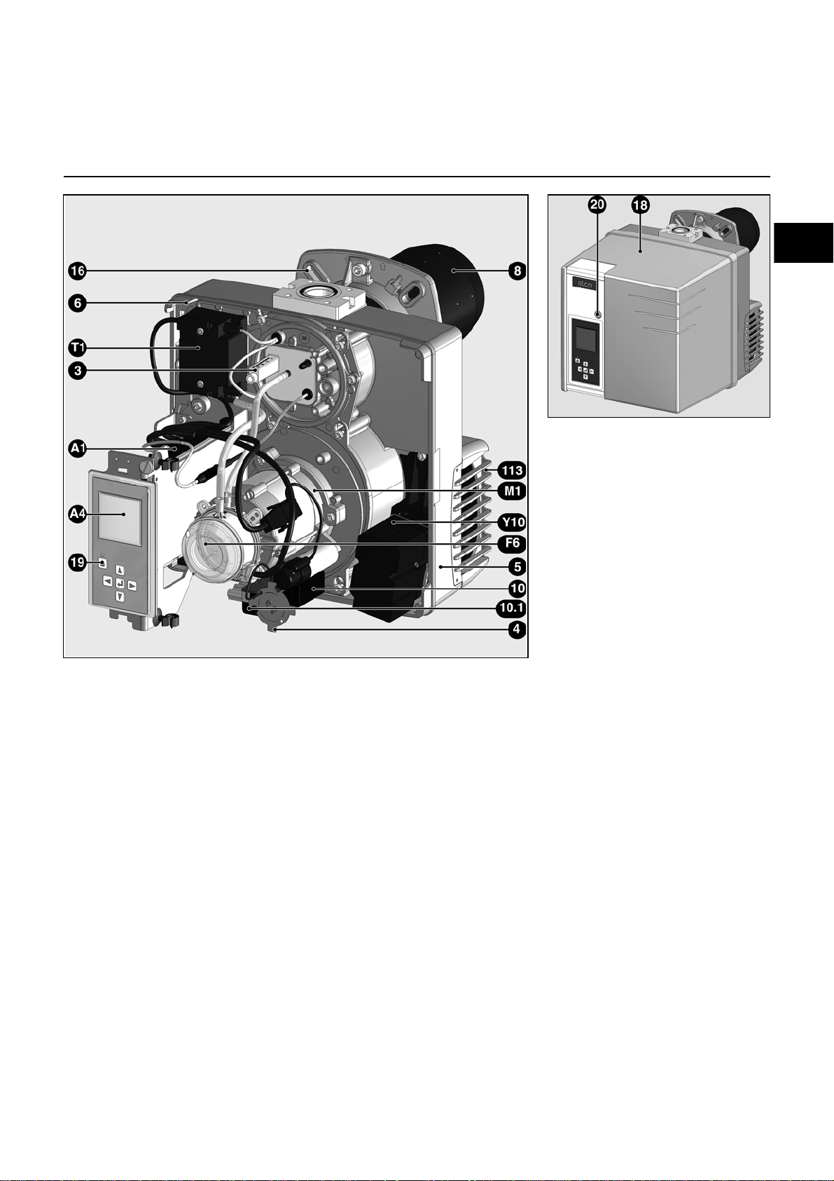
Burner description
A1 Control and safety unit
A4 Display
F6 Air pressure switch
M1 Blower motor
T1 Igniter
Y10 Air flap servomotor
3 Adjusting knob for dimension Y
4 Propane diffuser
5 Housing
6 Plate hanging device
(Maintenance)
8 Burner tube
10 7-pin connector
10.1 4 pin connector
16 Gas connecting flange
18 Cover
19 Release knob
20 Hood securing screw
113 Air intake box
09/2014 - Art. Nr. 4200 1038 2700A 3
Page 4
Operation
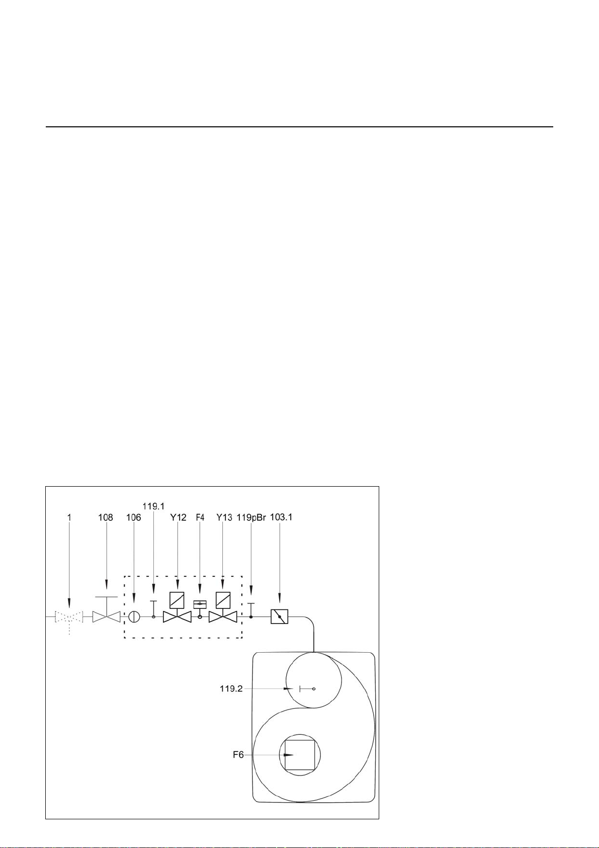
Compact train
Operation
Safety function
Description of functions
When first powering up, after a power
cut or a lockout, after the gas supply has
been cut or after a shutdown for 24
hours, a gas valve sealing test is
performed before the burner is started,
with the fan motor in operation. A preventilation time of 24 seconds begins
after the sealing test.
During the pre-ventilation time
- the air pressure is monitored
- a check is made for the presence of
any abnormal flame signals.
At the end of the pre-ventilation time
- the ignition is switched on
- the main and safety solenoid valves
are opened
- burner start-up
Monitoring
The flame is monitored by an ionisation
probe. The probe is fitted with insulation
to the gas head and is routed through
the turbulator into the flame zone. The
probe must not have any electrical
contact with earthed parts. The burner
switches to malfunction if a short circuit
occurs between the probe and the
burner earth. During burner operation,
an ionised zone is produced in the gas
flame through which a rectified current
flows from the probe to the burner tip.
The ionisation current must be at least
8 µA.
Safety functions
- If no flame is produced when the
burner is started (gas release), the
burner is switched off at the end of the
safety time which lasts no more than
3 seconds and the gas valve closes.
- If the flame is lost during operation,
the gas supply is cut within a second.
A new start-up sequence is activated.
If the burner starts, the operating cycle
starts running. Otherwise a lockout
occurs.
- If there is an air failure during preventilation or operation, a lockout
occurs.
- If there is a gas failure, the burner
either stops or will not start. As soon
as sufficient gas pressure is available
again, the burner restarts.
During the regulator shutdown
- The control thermostat interrupts the
heating request
- The gas valves close
- The flame goes out
- The blower motor stops
- The burner is ready for operation
F4 Gas pressure switch
F6 Air pressure switch
Y12 Safety solenoid valve
Y13 Main solenoid valve
1 Thermal safety valve (to be
installed by the fitter)
103.1 Gas throttle
106 Screen
108 Gas cut-out valve (to be
installed by the fitter)
119pBr Gas pressure measuring point
at the valve outlet
119.1 Gas pressure measuring point
upstream of the valves
119.2 Air pressure measuring point
CH note
In accordance with SSIGE instructions,
it is compulsory to install a gas safety
valve (mark 1) in the pipe.
DE Note
In compliance with the reference layout
applicable to boiler rooms, sites with gas
furnaces must be fitted with a thermal
gas shut-off valve (1).
09/2014 - Art. Nr. 4200 1038 2700A4
Page 5
Operation
en
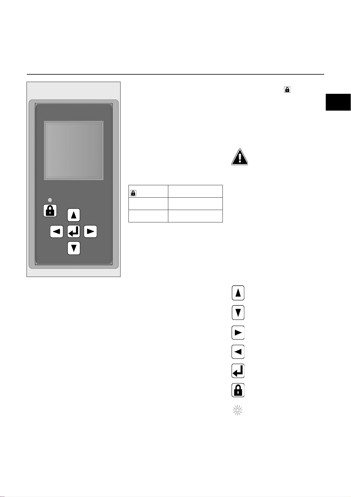
Control and safety unit BT 3xx
The control and safety unit BT 3xx
controls and monitors the forced draught
gas burner. The microprocessorcontrolled program sequence ensures
the maximum consistency of the cycle
times involved, regardless of
fluctuations in the mains voltage or
ambient temperature. The control and
safety unit is designed to detect power
failures. Depending on the parameter
assignment, the unit either switches to
malfunction mode or goes into the
standby position if the power supply falls
below the mains voltage. In the standby
position, there is an automatic restart as
soon as the set threshold value is
exceeded by 105%.
Pressing button
for ...
... 1 second ... the control and safety
... 2 seconds ... the control and safety
… causes ….
unit to unlock.
unit to lock
Manual locking and unlocking
Using the reset button , the control
and safety unit can be locked manually
(interlocked) or unlocked, provided the
unit is connected to the mains power
supply. This function must not be
confused with automatic locking and
fault acknowledgement in case of an
error.
Before installing or removing the unit or
any operation in the connection area,
switch off the supply to the device, check
for the absence of voltage and prevent
any reactivation. Otherwise there is risk
of electric shock. The control and safety
unit must not be
opened or repaired.
- Moves the cursor upwards
- Moves the cursor downwards
- Increases the marked value
- Moves the cursor to the right
- Reduces the marked value
- Moves the cursor to the left
Modifies/confirms the value shown
- Unlocks the control and safety unit
Red LED (flashes if a fault is
present)
09/2014 - Art. Nr. 4200 1038 2700A 5
Page 6

Operation
Air pressure
switch
Ignition
device
Terminal
Connector
Remote
unlocking
Solenoid valves
(1+2)
Heating
request
Min. gas
pressure
switch
Burner
safety
circuit
Boiler
safety
circuit
Solenoid
valve 3
Flame check
Fault
display
Burner motor
Terminal
L1 power supply
Grounding of
the burner
UV detector
additional
Ionisation
Flame
monitor
Connector
1 1 2 3 1 2 3 1 2 3 1 2 3 1 2 3 1 2 1 2 3 4
1 2 3
1 2 3
1 2 3
Pin
Pin
1 2 3 1 2 3
1 2 3
1 2 3 1 2 3 1 2
1 2
Terminal allocation chart
Pin Terminal Description Connector Pin Terminal Description Connector
1 1 Phase gas solenoid valve 1
2 2 Earth 1 30 Neutral conductor of the fuel-oil
3 3 Neutral conductor 2 31 Earth
1 4 Phase gas solenoid valve 2 3 32 Phase
2 5 Neutral conductor 1 33 Neutral conductor
3 6 Earth 2 34 Earth
1 7 Phase fuel valve 3 (optional)
2 8 Earth 1 36 Neutral conductor
3 9 Neutral conductor 2 37 Earth
1 10 Phase ignition transformer
2 11 Earth 1 39 Neutral conductor
3 12 Neutral conductor 2 40 Earth
1 13 Phase gas pressure switch min.
2 14 Earth 1 42 Neutral conductor
3 15 Phase 2 43 Earth
1 16 Phase burner safety circuit
2 17 Earth 1 45 UV flame monitor (-)
3 18 Phase 2 46 UV flame monitor (+)
1 19 Phase boiler safety circuit
2 20 Phase 2 48 Phase
1 21 Phase air pressure switch
2 22 Phase 4 50 Flame monitor (-)
1 23 Load (-)
2 24 Load (+)
3 25 Phase
1 26 Malfunction reset
2 27 Burner ON
3 28 Phase
X01
+
X02
X03
X04
X05
X06
X07
X08
X09
X10
1 29 Grounding of the burner
pump
3 35 Phase burner motor
3 38 Alarm output
3 41 L1 power supply
3 44 L1 power supply output
1 47 Ionisation probe
3 49 Flame monitor (+)
X26
X25
X24
X23
X22
X21
X20
09/2014 - Art. Nr. 4200 1038 2700A6
Page 7

Operation
Terminal
Display
PC interface
Gas
servomotor
Air
servomotor*
Fuel oil
servomotor*
1 2 3 4 5 6 1 2 3 4 5 6 1 2 3 4 5 6 1 2 3 4 5 6 1 2 3 4 5 6
Pin
Connector
en
Terminal allocation chart
Pin Terminal Description Connector
11
22
33
44
55
66
17
28
39
410
511
612
113
214
315
416
517
618
119
220
321
422
523
624
125
226
327
428
529
630
Display
PC interface
Servomotor gas
Servomotor air*
Servomotor fuel oil*
X30
X31
X32
X33
X34
* Terminal allocation depends on the design of the burner
09/2014 - Art. Nr. 4200 1038 2700A 7
Page 8

Operation
Boiler safety circuit
Gas safety circuit
Burner on
Minimum gas pressure swi t ch
Air pressure switch
Flame signal
Air flap
Gas flap
Transformer
Gas valve 1
Gas valve 2
Air motor
Fault
Control and safety unit BT 3xx gas operation
Legend to the sequence diagram
t1 Awaiting boiler safety circuit
Air pressure switch min. request
t2 Time for pressure build-up in the gas control line (only
when sealing test mode is activated, program sequence
for density test can vary, see sequence diagram for
density test)
t3 Servomotor running time
t4 Closing of gas flap
t5 Ventilation time
t6 Transformer activation time
Sealing test sequence diagram - no gas pressure at start of sealing test. Sealing test sequence diagram - gas pressure present at start of sealing
Legend to the sequence diagrams
t1 Ventilation time, always 2 seconds
t2 Delay time, always 2 seconds
t3 Sealing test time, configurable
t4 Filling time, configurable
The diagrams on this page have been taken from the operating instructions of the BurnerTronic BT300 BT320 BT340 from Lamtec.
Print no. DLT1200-11-aDE-002 Copyright© 2011 LAMTEC
t9 Safety time
t10 Operating phase
t11 Regulation
t12 Time for pressure release in the gas control line
t13 Postventilation time
t14 Servomotors under base load
t15 Post combustion time
t16 Flame extinction test
t17 Sealing test gas valve 2
test.
09/2014 - Art. Nr. 4200 1038 2700A8
Page 9
Operation
en
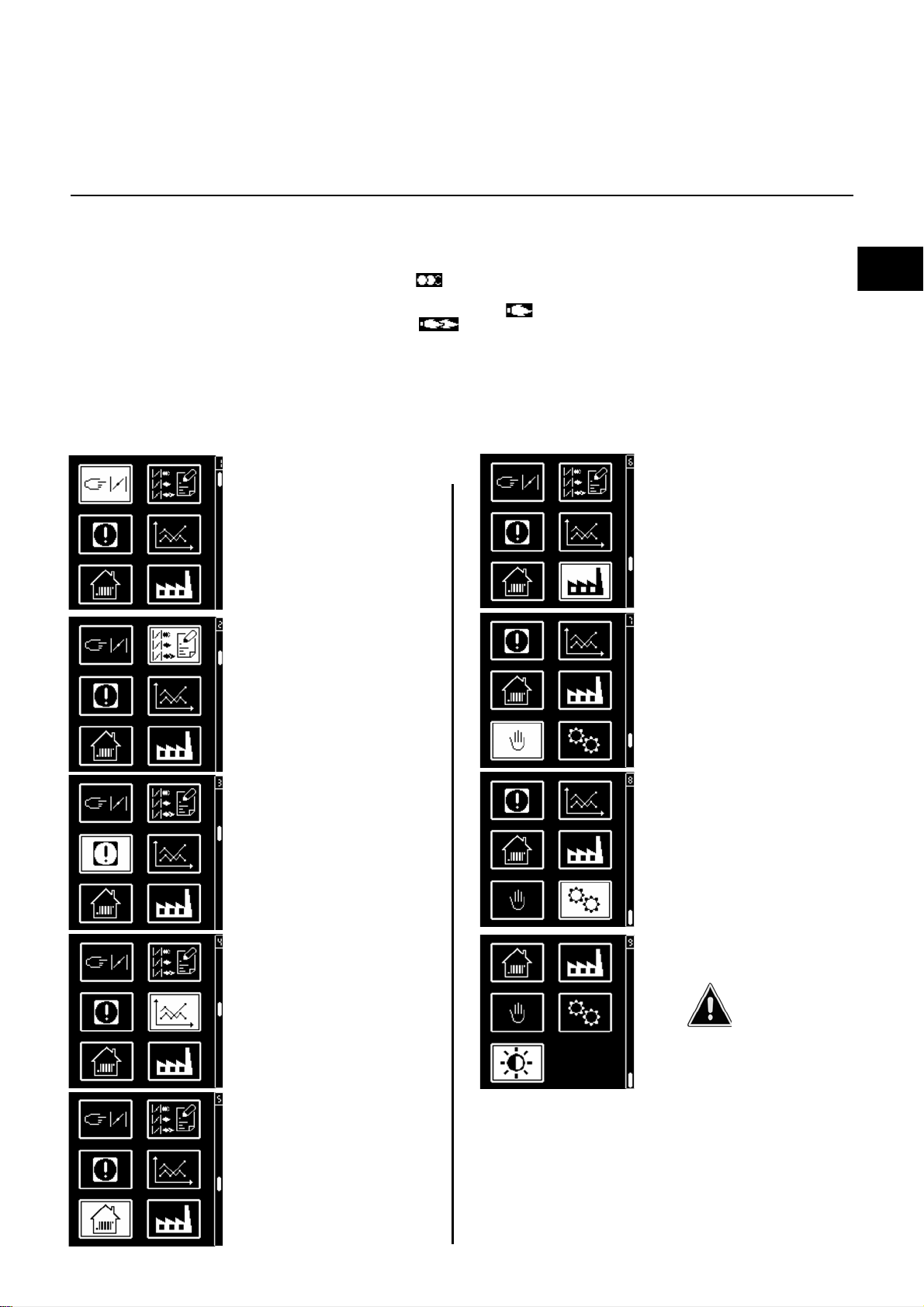
BT 3xx menu overview
In addition to the function of control and
safety unit, the control and safety unit BT
3xx also modulates the burner output by
controlling the air flap, gas flap, fuel oil
quantity regulation and frequency
converter (optional) in one electronic
circuit.
The electronic circuit controls the
opening of the gas flap and fuel oil flow
regulation proportional to the air flap
along a curve based on 10 setting points
During start up, the setting points are
defined based on the measurement
values of the combustion gas analysis.
This guarantees optimal combustion
• Menu 1: Setting the
• Menu 2: Display of the
over the burner's entire output
modulation range.
A separate burner ignition load can be
defined with the "Ignition position"
setting point .
The limit values of the control range are
defined by the min. output " " and
max. output " " setting points. In
addition, other optional functions, such
as sealing tests, reventilation or waiting
times can be activated.
The combustion control unit is operated
via a display and operating unit. The
parameters for the control and safety
unit are set using the display and 5 keys.
servomotors
setting points of the
servomotors in the
display unit
Operating values are shown in real time
on the display.
Pressing the keys gives access to 9
menus:
• Menu 6: Setting/
modification of
configurations for
industrial applications
• Menu 7: Manual mode
• Menu 3: Displaying
faults
• Menu 4: Statistical data
• Menu 5: Setting/
modification of
standard configurations
• Menu 8: Setting mode
- Menu 8 currently not
available
• Menu 9: Setting the
brightness and contrast of
the display
In these menus, it is
possible to adjust the
standard configurations of
the control unit. These are
pre-set in the factory.
The nearest customer
service department must be
contacted before any onsite modifications are made.
09/2014 - Art. Nr. 4200 1038 2700A 9
Page 10
Operation
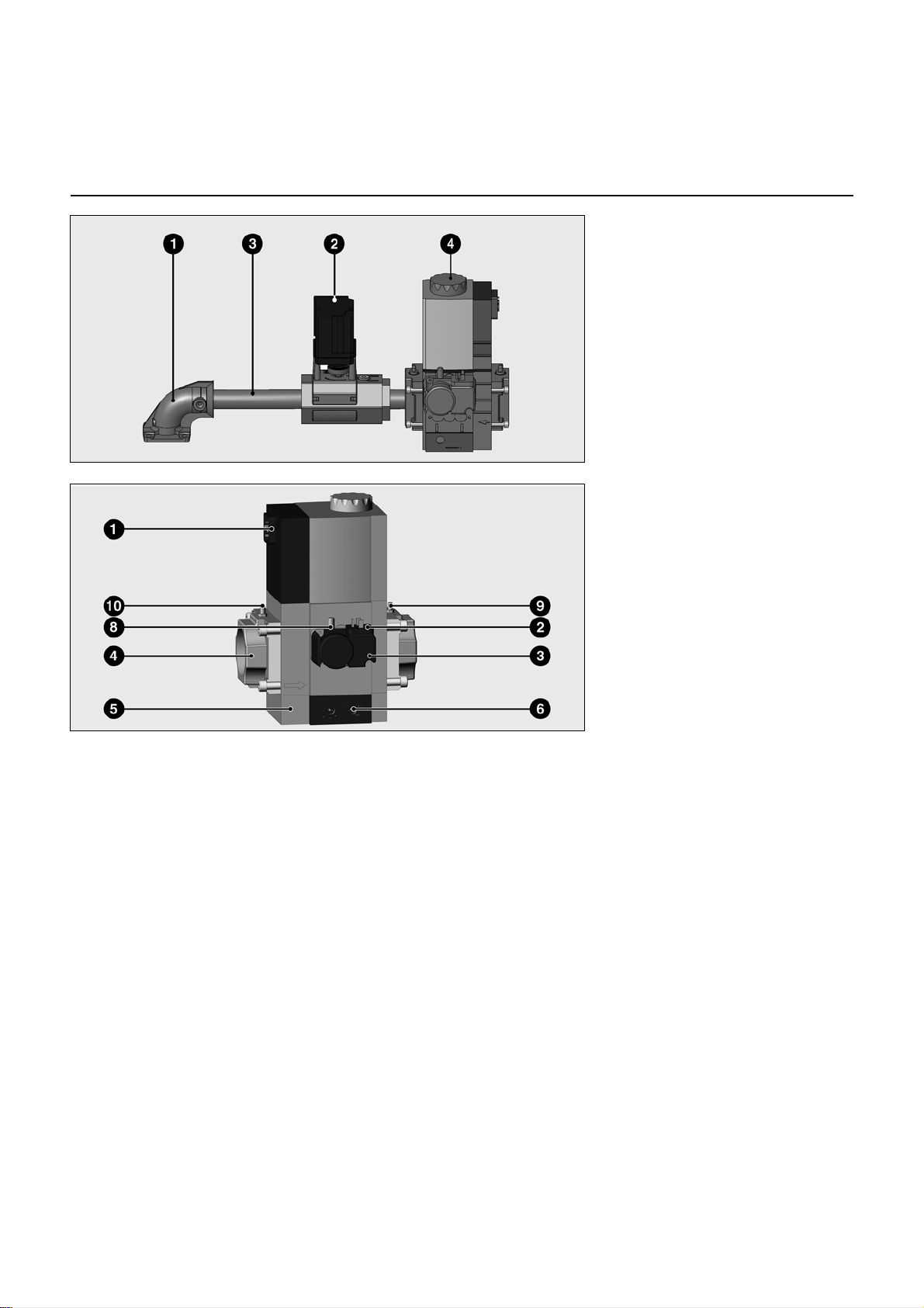
MBC-SE gas train
The gas train consists of:
- a gas connection flange 1 with O-ring
- a gas throttle 2, controlled by a
servomotor
- a gas connection pipe 3
- an MBC-SE gas valve train with gas
filter 4 (mini filter)
MBC SE gas valve
1 Electrical connection of solenoid
valves (DIN 43650)
2 Electrical connection of gas
pressure switch (DIN 43650)
3 Gas pressure switch
4 Gas inlet flange
5 Mini filter (under cover)
6 Gas pressure adjustment
screw pBr
8 Gas pressure measurement
tap G1/8 (inter-valve pressure)
9 Gas pressure measurement
tap G1/8 (outlet pressure pBr)
10 Gas pressure measurement
tap G1/8 (inlet pressure)
Installation position:
vertical with the coils facing upwards.
Where the lines are vertical, the coils
must be horizontal.
Description, technical data
The MBC-SE gas compact valve train is
a compact unit with 2 Class A solenoid
valves, a Class A servo pressure
regulator, a mini filter and a pressure
switch.
- Pressure switch GW A5: adjustment
range 5.....50 mbar
- Solenoid valve V1/V2 (fast-opening/
fast-closing)
- Adjustable servo pressure regulator
- Max. operating pressure 500 mbar
- Inlet pressure range
15-500 mbar
- Voltage/frequency:
230 V/50-60 Hz
Pressure regulator setting
The outlet pressure is set using
adjustment screw 6.
09/2014 - Art. Nr. 4200 1038 2700A10
Page 11

Installation
en
Burner installation
Burner installation
Burner flange 3 is equipped with
elongated slots and can be used with a
hole Ø of 150 - 184 mm. These
dimensions comply with EN 226.
The insertion depth of the combustion
components can be adjusted to the
geometry of the combustion chamber by
sliding pipe bracket 2 on the burner's
flame tube. The installed depth remains
the same during fitting and removal.
The burner is secured to the connecting
flange, and therefore to the boiler, via
pipe bracket 2. This completely seals off
the combustion chamber.
Burner tube installation depth and
brickwork surround
Unless otherwise specified by the boiler
manufacturer, heat generators without a
cooled front wall require brickwork or
insulation 5 as shown in the illustration
opposite. The brickwork must not
protrude beyond the leading edge of the
flame tube, and should have a maximum
conical angle of 60°. Space 6 must be
filled with an elastic, non-flammable
insulation material.
Installation:
• Secure connecting flange 3 to the
boiler using screws 4
• Fit pipe bracket 2 to the burner pipe
and secure using screw 1. Tighten
screw 1 to a maximum torque of 6 Nm.
• Turn the burner slightly, guide it into
the flange and secure using screw 5.
Removal:
• Loosen screw 5
• Turn the burner out of the bayonet
socket and pull it out of the flange.
For assembly in the position with
the volute facing upwards, unclip
the display from its support, turn it
over 180° and refit it.
Exhaust gas evacuation system
To avoid unpleasant noise emissions,
right-angled connectors should not be
used on the flue gas side of the boiler.
On boilers with reverse firing, the
minimum flame tube insertion depth A
should be observed as per the boiler
manufacturer's instructions.
Inspection glass cooling
The burner body can be equipped with
an R1/8" connection to support a line for
cooling the boiler's inspection glass.
• To do this, drill through cast iron
projection 6 and cut a 1/8" thread.
• Use accessories article no. 12 056
459 for the threaded union and
connection hose.
09/2014 - Art. Nr. 4200 1038 2700A 11
Page 12

Installation
Gas train
Gas train installation
• Check the correct position of the O-
ring J1 in the connecting flange.
• Secure the gas train on the burner so
that the gas train coils are in the upper
vertical position.
• Pay attention to the direction of
circulation.
• Route the connection cables C for the
gas train through cable gland and
connect it to the gas train.
On VG2.160/210 M/TC burners,
insert the diaphragm 2 delivered
with the gas train mounting parts
into the flange of the burner body.
09/2014 - Art. Nr. 4200 1038 2700A12
Page 13

Installation
VG2.120
VG 2.120
VG2.160/210
VG2.120
VG2.160/210
en
Checking the combustion components
Checking the combustion
components
• Remove the three screws W from the
cover.
• Remove the cover.
• Loosen lock nut E on the gas pipe
bracket
• Loosen the retaining bolt.
• Remove combustion components.
Setting to propane gas operation
VG2.120 burner
• Remove the shutter 3 and the
turbulator 4.
• Fit the adaptor 5 (supplied with the
housing).
• Fit the turbulator 4 without
shutter 3.
Setting to propane gas operation
VG2.160/210 burner
• Remove the shutter 3 and the
turbulator 4.
• Fit the adaptor 5 (supplied with the
housing).
• Fit the turbulator 4 and the shutter 3.
the
Checking the combustion
components
• Check the setting of the ionisation
probe and the ignition electrode in
accordance with the illustrations.
09/2014 - Art. Nr. 4200 1038 2700A 13
Page 14

Installation
Electrical connection
Checks before commissioning
Ionisation current measurement
General regulations applying to the
gas connection
• The gas train must only be connected
to the gas mains by a recognised
specialist.
• The cross-section of the gas line
should be of a size designed to
guarantee that the gas flow pressure
does not drop below the specified
level.
• A manual shut-off valve (not supplied)
must be fitted upstream of the gas
train.
• In Germany, a thermally triggered
shut-off valve (to be installed by the
customer side) must be fitted as
specified by the draft combustion
ordinance.
It is the responsibility of the fitter or his
representative to obtain approval for the
system at the same time as the burner is
commissioned. Only the fitter or his
representative can guarantee that the
system meets applicable standards and
regulations. The fitter should be in
possession of the corresponding official
permit, and should carry out the
corresponding sealing tests and purge
the system of air.
Electrical installation and connection
work must only be carried out by a
suitably qualified electrician. All
applicable regulations and directives
must be observed.
N.B. The applicable guidelines
and directives must be
observed, as well as the
electrical circuit diagram
supplied with the burner.
Electrical connection
• Check to ensure that the power supply
is as specified (230V, 50 Hz single
phase with neutral and earth).
Boiler fuse: 6.3A
Electrical connection
It must be possible to disconnect
the burner from the mains using an
omnipolar shutdown device
complying with the standards in
force. A device to protect against
short circuits must also be fitted
upstream of the burner's electrical
power supply.The burner and heat
generator (boiler) are connected by
a 7-pin connector 1 and a 4-pin
connector 2 (not supplied). The
diameter of the cables connected
to these connectors must be
between 8.3 and 11 mm.
Connecting the gas train
Connect the gas train to the plugs on the
burner (black to black, grey to grey).
Checks before commissioning
The following must be checked before
initial commissioning:
• That the burner is assembled in
accordance with the instructions given
here.
• That the burner is pre-set in
accordance with the values in the
adjustment table.
• Setting the combustion components.
• The heat generator must be ready for
operation, and the operating
regulations for the heat generator
must be observed.
• All electrical connections must be
correct.
• The heat generator and heating
system must be filled with water and
the circulating pumps must be in
operation.
• The temperature regulator, pressure
regulator, low water detectors and any
other safety or limiting devices that
might be fitted must be connected and
operational.
• The exhaust gas duct must be
unobstructed and the secondary air
system, if available, must be
operational.
• An adequate supply of fresh air must
be guaranteed.
Ionisation current measurement
To measure the ionisation current,
disconnect connector B10 and connect
a multimeter with a measuring range of
0-100 µA.
nd
The 2
at least 7 µA. It is also possible to read
the ionisation current on the display.
stage ionisation current must be
• The heating request must be
available.
• Sufficient gas pressure must be
available.
• The fuel supply lines must be
assembled correctly, checked for
leaks and bled.
• A standard-compliant measuring point
must be available, the exhaust gas
duct up to the measuring point must
be free of leaks to prevent anomalies
in the measurement results.
09/2014 - Art. Nr. 4200 1038 2700A14
Page 15

Commissioning
P3(°) P6 (°) P3(°) P6 (°)
40 80 10 0,8 0 0 10 20 30 5 5 10 20 28 13,0
50 100 20 0,9 10 10 20 30 45 15 15 25 38 55 10,0
60 120 30 1,3 15 15 30 40 80 15 15 30 35 65 14,0
40 80 10 0,8 0 0 10 20 30 5 5 10 20 28 17,5
50 100 20 0,9 10 10 20 30 45 15 15 25 38 55 15,0
60 120 30 1,3 15 15 30 40 80 15 15 30 35 65 18,0
40 80 10 0,8 0 0 10 20 30 5 5 10 20 28 7,5
50 100 20 0,9 10 10 20 30 45 15 15 25 38 55 7,5
60 120 30 1,3 15 15 30 40 80 15 15 30 35 65 8,0
40 130 10 1,4 0 0 20 40 60 12 12 26 43 57 10, 0
50 150 15 1,5 5 5 30 55 75 15 15 35 48 70 10, 0
60 160 25 1,7 13 13 30 60 90 17 17 30 44 55 13,0
40 130 10 1,4 0 0 20 40 60 12 12 26 43 57 12, 5
50 150 15 1,5 5 5 30 55 75 15 15 35 48 70 13, 0
60 160 25 1,7 13 13 30 60 90 17 17 30 44 55 16,0
40 130 10 1,4 0 0 20 40 60 3 3 20 36 50 6,5
50 150 15 1,5 5 5 30 55 75 5 5 27 40 65 7,5
60 160 25 1,7 13 13 30 60 90 12 12 25 36 65 8,0
45 140 10 1,4 0 0 20 40 60 13 13 26 50 65 10, 0
50 150 20 1,5 6 6 25 45 65 14 14 32 48 65 10, 0
60 185 35 1,7 10 10 35 65 90 15 15 35 45 75 13,0
45 140 10 1,4 0 0 20 40 60 13 13 26 50 65 12, 5
50 150 20 1,5 6 6 25 45 65 14 14 32 48 65 13, 0
60 185 35 1,7 10 10 35 65 90 15 15 35 45 75 16,5
45 140 10 1,4 0 0 20 40 60 5 5 20 40 65 0,6
50 150 20 1,5 6 6 25 45 65 8 8 27 40 60 0,6
60 185 35 1,7 10 10 35 65 90 10 10 30 42 75 8,0
Burner
Partload
Dimension
Y mm
gas
Bur ner output
kW
Ga s throttle positi on
Pressure
regulator
PBr
setting
mbar
Full
load
Ignition
load
(°)
Partload
P0 (°)
Full
load
P9 (°)
Ignition
load
(°)
Partload
P0 (°)
Full
load
P9 (°)
Furnace
press ure
mbar
Air flap position
VG2.210
M/TC
G20
G25
G31
VG2.120
M/TC
G20
G25
G31
VG2.160
M/TC
G20
G25
G31
en
Adjustment data
Type of
Only for the VG2.210 burner:
• When operating at low gas pressure, it
is necessary to remove the diaphragm
4 from the gas inlet.
The adjustment values above are guide values and facilitate commissioning. The factory settings are in bold set against a grey
background. The final settings are essential in ensuring that the burner functions as well as possible.
Setting the gas pressure switch
• Remove the transparent cover.
• Provisionally set to 15 mbar.
Setting the air pressure switch
• Remove the transparent cover.
• Provisionally set to 1 mbar.
09/2014 - Art. Nr. 4200 1038 2700A 15
Page 16

Commissioning
Air regulation
MBC-SE gas train setting
Pressure regulator setting
Air regulation
Combustion air is regulated at two
points:
• on the pressure side, using the gap
between the turbulator and the burner
tube.
• on the vacuum side, by the air flap
driven by servomotor Y10.
The regulation of air in the burner head
affects not only the air flow but also the
mixing zone and the air pressure in the
burner tube. Turning screw A
- to the right for more air
- to the left for less air
• Adjust dimension Y in accordance
with the settings table.
Air regulation by air flap
Air is regulated on the vacuum side by
an air flap. This is driven by servomotor
Y10.
MBC-SE gas train setting
Pressure regulator setting
The gas pressure regulator is set at 10
mbar in the factory. Check the gas
pressure after the first time the burner is
started (measuring point at gas train
outlet flange) and if necessary, correct
gas pressure pBr via adjustment screw
S in accordance with the table on page
15. After start up, no further changes
should be made.
09/2014 - Art. Nr. 4200 1038 2700A16
Page 17

Commissioning
en
Confirmation of "Manual Handshake" data
The following sequence for confirming or cancelling the data entry is the same for a number of different changes to the
parameters. For this reason, this sequence is not illustrated in detail for each of the parameter settings outlined below. The
parameter modifications which require a "Manual Handshake" are highlighted on the following pages.
These parameter modifications are assigned the following reference:
Manual Handshake
You are now asked to confirm the modifications that have been made.
Accept or cancel the entry
The "Manual Handshake" is explained below using menu 5 as an example.
The following parameters have been modified in the example:
- Density test activated after burner cycle
- Post-ventilation time activated (5 seconds)
The following screen appears once the parameter has been set and the data entry confirmed.
You are asked to confirm the data within 7 seconds. In this case: "Density test after burner cycle
activated".
A counter displaying the remaining time appears in the bottom right-hand corner of the screen.
Only confirm the displayed settings if they correspond with your specifications. The
entry can be accepted if both values are identical. The entry can be cancelled if there
is a deviation in values.
To confirm and save the parameter modification, select symbol and confirm with key .
To cancel the modifications, select symbol and confirm with key . Alternatively, you can
wait until the time has expired.
No modifications are made.
Note:
You will return to the previous menu if the procedure is cancelled. The previous unmodified
settings are displayed.
If you accept these values, a second screen appears.
In this case: "Post-ventilation time activated, duration 5 seconds".
Once again, the data must be confirmed within 7 seconds.
Only confirm the displayed settings if they correspond with your specifications. The
entry can be accepted if both values are identical. The entry can be cancelled if there
is a deviation in values.
Confirm the data or stop the procedure as described above.
If all values of the "Manual Handshake" have been confirmed, the data is saved in the
BurnerTronic. The modifications have been made and the procedure is completed. You return
to the starting screen.
Note:
If several parameters of a menu have been changed simultaneously (as in the example), the
individual modifications must be confirmed separately.
09/2014 - Art. Nr. 4200 1038 2700A 17
Page 18

Commissioning
Menu 1: setting the servomotors
Pre-setting without flame
Setting is carried out in 2 phases:
- Pre-setting without flame
- Setting the flame, to fine tune the
settings based on the combustion
results
Important
At this point, no setting position for the
servomotors has been defined,
therefore the burner cannot be started
under these conditions.
When the burner is switched on, the
control and safety unit displays the
screen below.
Access codes must be entered for the individual menus at various points in these instructions. Menu areas
protected by access codes are solely reserved for authorised, qualified and trained personnel.
The following menu description explains the menu for gas operation (figures), but is also valid for fuel oil operation.
Any deviations are noted where relevant.
• For the next step, press
key .
The control and safety unit
then opens the settings mode.
The screen displays the
factory pre-settings for the
different positions of the fuel
and air flap (here: for an
electronically modulated gas
burner)
The menu displays all the
The overview of the menus is
displayed, and the air and gas
flap position settings menu is
settings data using three
consecutive screens (air and
gas flap positions), i.e. for:
selected.
- Ignition position: (when
• Open the settings menu by
pressing the key.
the menu is opened, the
cursor is positioned here)
- Output points P0 to P9
The access code must be
entered at this point
(Access code 1)
• Increase or decrease the
value in increments by
repeatedly pressing
or .
• When the first figure has
been set, move the cursor to
the right by pressing .
• Repeat the operation until
you reach the last figure.
• Confirm the access code by
pressing key .
Special feature for
operation with
the frequency converter:
The fan motor is activated when menu
1 is accessed. Activation must be
confirmed, the screen is displayed as
shown on the left (Manual Handshake).
Continuous ventilation is activated for
the pre-set time period in menu 1. This
is necessary to obtain a feedback value
for the frequency converter channel.
This setting is deactivated again at the
end of menu 1.
09/2014 - Art. Nr. 4200 1038 2700A18
Modifying a value for the servomotor position:
- To modify the value of a position, move the cursor to the
corresponding location with the key.
- Select the value to be modified using the key, the
selected value will flash.
- Increase or decrease the value (in increments of 0.1°) by
repeatedly pressing or . For large modifications, press
and hold the or key, the value will scroll quickly up or
down.
- Confirm the new value using the key. The value stops
flashing.
Page 19

Commissioning
en
Menu 1: setting the servomotors
Pre-setting without flame
End of settings menu without flame
When all the positions of the servomotors have been determined according to the required
settings, it is possible to move on to the next set-up stage, setting with flame.
To do this, place the cursor in the lower part of the screen on the symbol and confirm by
pressing the key.
Only for operation with the frequency regulator:
Manual Handshake
Accept or cancel the entry.
Note: continuous ventilation is deactivated when this menu is exited.
If you want to exit the menu without saving the pre-settings, position the cursor on the symbol
and confirm with the key.
A processing screen now appears for a short time. The "Setting with flame" comes after this
(see page 20).
You are now asked to confirm the modifications that have been made.
It is also possible to delete all the settings at this point. To do this, position the cursor on the
symbol and confirm with the key.
The screen opposite appears.
At this point, it is possible to:
- delete the values; to do so, move the cursor to the symbol and confirm with the key. A
processing screen appears for a short time
- Exit the screen without modification using the symbol.
The previous menu is displayed.
General advice before starting the burner
Function check
All safety equipment must be checked to
Risk of deflagration
Continue to monitor the CO, CO2 and O2
and soot content of the exhaust gases
during setting. Improve combustion
values in the event of CO emissions and
soot formation. The CO content should
be <10 ppm. The soot content should
be <1.
ensure that it is fully functional as part of
initial commissioning and also after
servicing or if the system has been out of
operation for any significant period of
time.
The check must be carried out following
the guidelines in the section entitled
Checking the safety equipment.
09/2014 - Art. Nr. 4200 1038 2700A 19
Page 20

Commissioning
Menu 1: setting the servomotors
Setting with flame
- If the boiler heating
request is not present, the
burner remains on standby.
In this case, it is still possible
to return to the previous
setting menu "Pre-setting
without flame". To do so,
confirm with the key.
- As soon as there is a
boiler heating request
(contacts X10-2 and X10-3
closed), the burner starts.
The air flap is opened to move
to the pre-ventilation position.
Air pressure switch test
The air flap switches to the
ignition/pre-ignition position.
The fuel valve opens.
Awaiting flame signal
If no flame is detected at the
end of the safety time, the
control and safety unit
switches to malfunction mode.
Gas valve sealing test*
(the remaining time is
displayed in the menu in the
bottom right-hand corner)
Pre-ventilation
* only for burners with integrated sealing test and only
for gas operation
Flame detected
Flame stabilisation
The control and safety unit
awaits regulation
authorisation.
09/2014 - Art. Nr. 4200 1038 2700A20
Page 21

Commissioning
en
Menu 1: setting the servomotors
Setting with flame
Setting the ignition position
If a flame has been detected, the control and safety unit sets the burner to the ignition position as
soon as it receives the regulation authorisation.
- Set the fuel controller position and the air flap position according to the desired output level.
While doing so, constantly check the combustion values (CO, CO2 O2, soot, NOx). If required,
adapt the gas and fuel oil pressures at the valve and fuel-oil pump.
- Modify the position of the servomotors in the ignition position (lines with symbol). Proceed
as described on page 18, in the paragraph "Modifying the value of a servomotor position
setting".
- Warning: when modifying the value, the servomotor will move in real time. As a consequence,
the combustion values must be constantly checked.
The burner remains in ignition load.
Setting points P0-P9.
• Check the gas and fuel oil pressure. In the event of subsequent modifications, all setting values
must be corrected. For this reason, fine setting of the burner from point P9 must be carried out,
if necessary. At each setting point, check the combustion values and if necessary, change the
fuel controller position or the air flap position. To do so:
• Select air or fuel with or .
• Activate via (the cursor flashes).
• Change the value via or .
• Confirm with .
The next setting point is accessed using the key.
Note:
The values for each setting point are not saved until the next setting point is accessed. Each point
must be defined. It is not possible to skip individual points, as opposed to when setting without
flame. Only when all points (P0...P9) have been defined can the limit values for minimum and
maximum be set.
Further procedure:
• Enter the setting values in the log.
• Initiate all setting points individually
• Check the burner output at the maximum setting and raise or lower the fuel and air values if
necessary.
• Once all setting points P0 to P9 have been optimised, confirm them by navigating to the next
screen. To do so, press the key at point 9.
Note: The next screen can only be activated once all points (P0...P9) have been defined
• The burner moves to the lower operating point, symbol .
• Check the exhaust gas temperature, emissions and output at low load, if required, adapt the
burner output by correcting .
- To change:
• Activate with (the cursor flashes).
• Change the value via or
• Confirm with
Continue with the key
The burner moves to the upper operating point, symbol .
• Check the exhaust gas temperature, emissions and output at low load, if required, adapt the
burner output by correcting .
- To change:
• Activate with (the cursor flashes).
• Change the value via or
• Confirm with
•
Continue with the key
The setting procedure is completed at this point, the burner switches to operating mode.
The burner switches to the lower operating point and waits for a heating request. The burner
operates within the preset output range ( - ) according to the settings of the control
thermostat.
09/2014 - Art. Nr. 4200 1038 2700A 21
Page 22

Commissioning
Menu 1: setting the servomotors
Setting with flame
It is only possible to adjust (limit) the low load and high load if, for each higher power point, all of
the channels also have setpoint values which are always higher. If this is not the case, the screen
opposite is displayed.
As it is not possible to limit the power range configured, the minimum and maximum operating
points (P0....P9) are automatically defined as the limit.
Example: 1
When the working field is set to always increase, it is possible to adjust the low load and high load.
Example: 2
When the working field is set to not always increase, it is not possible to adjust the low load and
high load.
The highlighted values in the box do not constantly increase.
Take care with dual fuel burners. The limits for low load and high load apply to both gas and fuel
oil operation. It is not possible to define the different limits for fuel oil and gas. If, for example, the
values are modified during gas mode, these values are also modified automatically for fuel oil
mode.
If values have already been defined, the values for the limits of low and high loads previously
specified for the other fuel are displayed in the menu point (left image).
If the values are modified, they must be confirmed for both fuels.
09/2014 - Art. Nr. 4200 1038 2700A22
Page 23

Commissioning
en
Menu 1: setting the servomotors
Setting with flame
Operating mode
Closing the "Setting with flame" menu
The burner setting is now complete. It is still possible, however, to correct the individual values.
To do this, position the cursor on the value to be modified, using the or key.
At any time, the following options can always be used to close the "Setting with flame" menu:
- Restart the burner setting procedure, passing through the presetting phase (without entering a
password). To do this, position the cursor on the symbol and confirm with the key. All
the setting values already saved remain available. This is especially essential for testing a new
ignition position.
- Save the specified values and end the setting procedure. To do this, position the cursor on the
symbol and confirm with the key. Confirm and close the selected settings with symbol .
Manual Handshake
You are now asked to confirm the modifications that have been made.
Accept or cancel the entry
- The burner is now ready to operate and can be immediately controlled by the boiler regulation.
- Exit the settings menu without reaching the end of the setting procedure. To do this, position
the cursor on the symbol and confirm with the key. All the servomotor positions saved
up to this point are recovered by calling up the settings menu again.
Operating mode - Display of the operating status, the flame signal and the operating time
Once setting of the burner has been completed, it switches to operating mode.
The current operation of the burner (operation at min. output, medium output or max. output) is
indicated by the cursor.
When ionisation is employed for flame monitoring (gas operation only), the strength of the signal
is shown at the bottom of the display. The possible display range is between 0 μA and 30 μA. A
good quality signal is one that is above < 9 μA in all load points.
If ionisation is not employed for flame monitoring, either 0% or 100% is displayed.
0% - there is no flame signal
100% - there is a flame signal
If O2/CO regulation is employed, the current O2 value can be read in the bottom right-hand
corner of the display.
09/2014 - Art. Nr. 4200 1038 2700A 23
Page 24

Commissioning
Setting the gas pressure switch
Setting the air pressure switch
Setting the gas pressure switch
• To set the switch-off pressure: remove
the gas pressure switch cover.
• Install a gas pressure pBr measuring
instrument.
• Start the burner. Switching to
maximum power.
• Reduce the pressure upstream of the
gas train by gradually closing the
manual valve, until
- the gas pressure pBr upstream of
the gas train drops
- the stability of the flame is reduced
- the CO level increases
- or the flame signal deteriorates
considerably
Setting the air pressure switch
• Install a pressure measuring device.
To do this, install a T union in the air
tube.
• Set the burner to its maximum
operating power.
• Set the switch-off point to
approximately 15% below the switchoff pressure read.
• Turn the dial clockwise until the gas
pressure switch shuts down the
burner.
• Continue turning the dial clockwise to
set the gas pressure switch to 10%
above the shutdown value determined
above.
Checking the switch-off pressure
• Open the manual shut-off valve
• Start the burner
• Close the manual shut-off valve
The gas failure procedure should start
without the control unit locking.
09/2014 - Art. Nr. 4200 1038 2700A24
Page 25

Commissioning
en
Displaying the setting data from the manual control display
Displaying the setting data from the manual control display
Once the burner setting procedure has been successfully
completed, the servomotor positions for all the operating states are
fixed in the control and safety unit. A backup copy of the values is
saved in the display.
To do this, press the key, the screen opposite is displayed.
Using the key select the menu "Displaying the setting data"
and confirm with the key.
The screen opposite appears. All setting data is displayed in three
consecutive screens. Scroll through by selecting symbols or
and confirming with the key.
The top right-hand corner of the display shows the fuel to which the
current values apply. To switch between the fuel oil and gas
parameters, you must navigate to the corresponding symbol and
confirm with .
Exit the menu using the symbol.
Note: setting points are automatically stored at the end of the
Caution: the values shown in this menu correspond with the values that were last successfully set with the current
manual control display using menu 1 (menu 1 must have been completed in its entirety). However, these values
do not have to correspond with the values saved in the BT300. Any modifications to curve parameters which were
carried out after the last start-up or burner setting with the manual control unit using PC software, are not taken into
consideration. If the values in the menu deviate from the ones in the BT300, the values can be synchronised with
a restart (using the manual control unit - menu 1).
setting procedure for servomotors (menu 1).
The setting procedure (menu 1) must be entirely
completed in order to save the data. Only once the
burner has switched to regulation for the first time are
the setting values in the display saved.
09/2014 - Art. Nr. 4200 1038 2700A 25
Page 26

Maintenance
Maintenance
Burner and boiler servicing must only be
carried out by a professionally qualified
heating engineer. The system operator is
advised to take out a maintenance
contract to guarantee regular servicing.
Depending on the type of installation,
shorter maintenance intervals may be
necessary.
• Switch off the power supply before all
maintenance and cleaning work.
• Use original spare parts.
Work recommended as part of annual
burner maintenance:
- Burner test run, input measurement in
the boiler room
- Clean the combustion components
and replace defective parts if
necessary
- Clean the fan wheel and the fan
- Clean the gas filter; replace it if
necessary
- Visual inspection of burner electrics,
repair if necessary
- Check burner start characteristics
- Sealing test
- Burner safety devices function check
(air pressure/gas pressure switches)
Cleaning the fan wheel
• Remove the plate and attach it in the
service position (see illustration).
• Remove and clean the fan wheel and
replace it if necessary. Refit in the
reverse order.
- Flame monitor and automatic
combustion control unit function check
- Commissioning the burner
- Check the gas flow
- Correct the adjustment values if
necessary
- Draw up a measurement report
General checks
- Emergency stop button function check
- Visual inspection of gas lines in the
boiler room
Checking the combustion
components
• Remove the burner hood.
• Disconnect the ignition cable on the
transformer side.
• Remove the three screws W from the
cover.
• Remove the cover.
• Loosen lock nut E on the gas pipe
bracket
• Loosen the retaining bolt.
• Remove the combustion components.
• Check the condition of the baffle plate.
• Check the position of the ignition
electrode and the ionisation probe.
• When refitting, make sure that the
cable is routed correctly and that Oring J2 is correctly seated.
• Check it is airtight.
Fitting the fan wheel
When changing the motor or the fan
wheel, refer to the positioning diagram
opposite. The internal flange A of the fan
wheel must be aligned with the plate B.
Insert a straight edge between the
blades of the fan wheel and bring A and
B to the same height. Tighten the conepoint screw on the fan wheel.
09/2014 - Art. Nr. 4200 1038 2700A26
Page 27

Maintenance
en
Maintenance
Replacing the flame tube
It is necessary to remove the burner for
this work.
• Loosen the clamping screw on the
connecting flange.
• Turn the burner out of the bayonet
socket, lift it slightly and pull it out of
the connecting flange.
• Place the burner on the floor.
• Undo the 4 screws S.
• Pull the flame tube out towards the
front.
• Fit and secure the flame tube.
The flame tube may be hot
Filter replacement
• The filter element of the multiblock
must be checked at least once a year
and replaced if clogged.
• Loosen the screws of the filter cap on
the multiblock.
• Remove the filter element and clean
its housing.
• Do not use any pressurised cleaning
products.
• Replace the filter element with a new
element.
• Screw the cover back into place.
• Reopen the manual shut-off valve.
• Check it is airtight.
• Check the combustion values.
Cleaning the cover
• Do not use abrasive products or
products containing chlorine.
• Clean the cover with water and a
suitable cleaning product.
• Refit the cover.
Important
Combustion values must be checked
under normal operating conditions
(boiler room door closed, hood fitted,
etc.) after any work is carried out
inside the unit. Record the results in
the relevant documents.
Checking the flue gas temperature
• Check the flue gas temperature at
regular intervals.
• Clean the boiler if the flue gas
temperature is more than 30 °C above
the value measured at the time of
commissioning.
• Use a flue gas temperature gauge to
make the check easier.
Cleaning the air box
• Remove fastening screws V from the
air box.
• Remove the air box, clean it and refit it
in reverse order.
• Check that the air flap and the
servomotor are correctly positioned.
09/2014 - Art. Nr. 4200 1038 2700A 27
Page 28

Servicing
Menu 3: Fault memory
Entering a telephone number for the maintenance company and the
maintenance contract number
Menu - Fault memory
To access the fault memory menu, press any key when the burner is ready for operation or in operation, or
when it is in malfunction mode. It is not possible to access the fault memory menu during the start-up phase.
The general menu screen will appear. Using the , , , or keys, place the cursor on the fault
memory menu symbol, and confirm using the key.
The details of the last fault to appear are indicated by the flashing symbol. This includes the fault code, flame
intensity, air and fuel controller position and burner operating time up to the lockout point.
Using the and keys, it is possible to call up the details of the last 5 faults to have appeared (the fault
number is displayed in the upper left corner of the display). After the details of the last 5 faults, the telephone
number of the after-sales department as well as the maintenance contract number (no values are entered in
the factory) and the menu point "Delete fault memory" are shown.
• Exit the menu using the key.
Entering a telephone number for the maintenance company and the maintenance contract
number
When the corresponding symbol appears on the display:
• Press the key, the first digit starts to flash.
• Using the or keys, change the figure to the value required (underscore = empty field).
• Using the key, move on to the next figure.
• When the number is complete, save using the key.
• The last menu point of menu 3 makes it possible to delete the fault memory (see explanation on the
next page).
Fault diagnosis help symbols
Note: The fault displays described below only show fault diagrams for gas operation (images); however, they
are also valid for fuel oil operation. Any deviations are noted where relevant. The symbol shown in the top
right-hand corner of the display indicates the fuel for which the fault has occurred.
Symbol Cause Symbol Cause Symbol Cause
The control and
safety unit has been
manually locked
Air pressure switch
malfunction at burner
startup
(air pressure switch
activated)
- Combustion air still
present
- Pressure switch
defective (contacts are
welded)
- Pressure switch
incorrectly set
Air pressure switch
malfunction at burner
startup (air pressure
switch not switching)
- No combustion air
- Pressure switch
defective
- Pressure switch
incorrectly set
Stray light
Flame extinguishing
during operation
Internal fault with the
air servomotor
Internal fault with
fuel servomotor
Gas pressure switch
malfunction
- No gas pressure
- Pressure switch
defective
- Pressure switch
incorrectly set
Safety valve fault (gas
operation only)
- Leak in safety gas valve
- Main gas valve not
opening (defective)
- Pressure switch
defective (contacts are
welded)
No defined curve
Fault in boiler safety
circuit during
operation
Fault in burner
safety circuit during
operation
No flame at end of
safety time
Main gas valve fault (gas
operation only)
- Leak in main gas valve
- Safety valve not opening
(defective)
- Insufficient gas pressure
- MIN pressure switch
defective
- MIN pressure switch
incorrectly set
Unknown fault
For details, see the
fault code list
09/2014 - Art. Nr. 4200 1038 2700A28
Page 29

Servicing
en
Menu 3: Fault memory
Entering a telephone number for the maintenance company and the
maintenance contract number
Continued: Fault diagnosis help signals:
Symbol Cause Symbol Cause Symbol Cause
Power supply fault
- min. supply
voltage not reached
Boiler safety circuit
fault when starting
burner
The following message appears in the display for the last menu point:
Using , navigate to and confirm with the key to delete the fault memory.
Burner safety circuit
fault when starting
burner
Fuel oil pressure switch
malfunction
- No fuel oil pressure
- Pressure switch
defective
- Pressure switch
incorrectly set
- Pump defective
- Fault in fuel oil supply
Air pressure switch
malfunction during
burner operation
(decreased air
pressure switch signal)
- No combustion air
(fan has failed)
- Pressure switch
defective
- Pressure switch
incorrectly set
You are now asked to confirm that you want to delete the fault memory.
Navigate to and confirm with the key to delete.
Navigate to and confirm with the key to quit and exit the menu.
09/2014 - Art. Nr. 4200 1038 2700A 29
Page 30

Servicing
Menu 4: Operating statistics
Operating statistics menu
To access the operating statistics menu, press any key when the burner is ready for operation or
in operation, or when it is in malfunction mode. It is not possible to access the operating statistics
menu during the start-up phase.
The general menu screen will appear. Using the , , , or keys, place the cursor on the
operating statistics menu symbol, and confirm using the key.
The operating statistics menu comprises 3 screens. You can navigate between the different
screens using the and keys.
- Flame detection time for last burner start-up
- Average flame detection time for the last 5 burner start-ups
- Total number of burner start-ups
- Number of burner start-ups, gas operation
- Number of burner start-ups, fuel oil operation (if available)
- Total operating time since the last counter reset
- Total number of operating hours in gas operation since the last counter reset
- Total number of operating hours in fuel oil operation since the last counter reset
09/2014 - Art. Nr. 4200 1038 2700A30
Page 31

Servicing
en
Setting the brightness and contrast of the display
This menu offers access to the display contrast and brightness settings.
To access the menu, press any key when the burner is ready for operation or in operation, or
when it is in malfunction mode.
• The general menu screen will appear. Position the cursor on the symbol for setting the display
and confirm with the key.
• Modify the settings using the and keys for the contrast (in increments of 2), or the
and keys for the brightness (in increments of 10).
• Position the cursor on the symbol and confirm the setting with the key.
• All modifications entered are discarded using the symbol. The burner returns to the previous
operating mode.
09/2014 - Art. Nr. 4200 1038 2700A 31
Page 32

www.elco.net
Made in EU.
Non contractual document.
09/2014 - Art. Nr. 4200 1038 2700A32
 Loading...