

Page 1
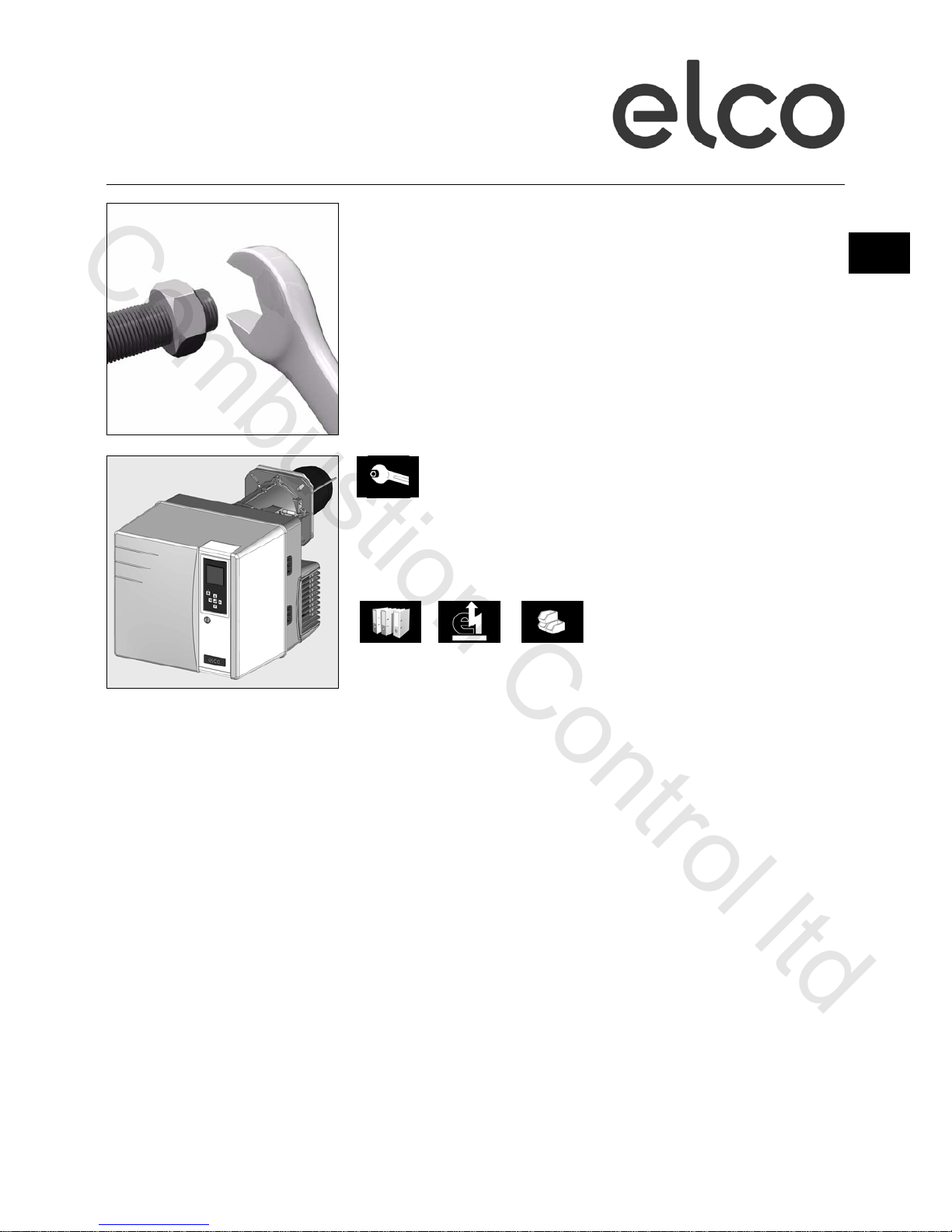
02/2011 - Art. Nr. 4200 1027 9501B
VG3.290 D
VG3.360 D
Operating instructions
For specialist installation engineers
Gas burners ........................................... 2-28
en
de, fr..................................... 4200 1021 2101
it, nl ...................................... 4200 1021 2201
............................................. 4200 1021 2002
Combustion Control ltd
Page 2
02/2011 - Art. Nr. 4200 1027 9501B2
Overview
Contents
We accept no responsibility for damage
arising from:
- inappropriate use.
- incorrect installation and/or repair on the
part of the buyer or any third party,
including the fitting of non-original parts.
Final delivery and instructions for use
The firing system fitter must supply the
operator of the system with operating and
maintenance instructions on or before final
delivery. These instructions should be
displayed in a prominent location at the
point of installation of the heat generator,
They should include the address and
telephone number of the nearest customer
service centre.
Notes for the operator
The system should be inspected by a
specialist at least once a year. Depending
on the type of installation, shorter
maintenance intervals may be necessary!
It is advisable to take out a maintenance
contract to guarantee regular servicing.
Overview Contents.................................................................... 2
Important information ................................................ 2
Burner description ..................................................... 3
Operation Operation, safety operation ....................................... 4
Automatic combustion control unit ......................... 5-7
Terminal allocation chart, connection socket.........8-9
MB-ZRDLE gas train............................................... 10
Assembly Burner assembly, gas train assembly ............... 11-12
Checking the combustion components................... 12
Electrical/gas connection ........................................ 13
Testing before start up ............................................ 13
Commissioning Adjustment data ..................................................... 14
Air regulation........................................................... 15
Setting the MB-ZRDLE gas train............................. 16
Pre-adjustment without flame ...........................17-18
Setting the flame ................................................ 19-21
Saving the adjustment values in the display ..........22
Servicing Maintenance ..................................................... 23-24
Troubleshooting ................................................. 25-26
Fault diagnosis menu,
Operating statistics menu .................................. 27-28
Declaration of conformity
for gas burners
We, certified company No. AQF030,
F-74106 ANNEMASSE Cedex,
declare under our sole responsibility
that the products
VG3.290 D
VG3.360 D
conform to the following standards
EN 50165
EN 55014
EN 60335-1
EN 60335-2-102
EN 60555-2
EN 60555-3
EN 676
Belgian royal decree dated 08/01/2004
These products bear the CE mark in
accordance with the stipulations of the
following directives
2006/ 42/EC Machinery directive
2004/108/EC EMC directive
2006/ 95/EC Low voltage directive
92/ 42/EEC EEC Working
efficiency directive
Annemasse, 6th October 2009
M. SPONZA
Important information
VG3.290 D and VG3.360 D burners are
designed for the low-pollutant combustion
of natural gas and propane gas. The
design and function of the burners meet
standard EN 676. They are suitable for use
with all heat generators complying with
standard EN 303 or for use by hot air
generators complying with standard DIN
4794 or DIN 30697 within their respective
performance range. Any other type of
application requires the approval of ELCO.
Installation, commissioning and
maintenance must only be carried out by
authorised specialists and all applicable
directives and regulations must be
complied with.
Burner description
VG3.290 D and VG3.360 D burners are
two-stage fully automatic monoblock
devices. The special design of the
combustion head enables combustion with
low levels of nitrogen oxide and increased
output. Class 3 type-approval in
accordance with EN676 certifies that the
lowest emission values have been
achieved and means that the national
environmental regulations have been met
AT: KFA 1995, FAV 1997
CH: LRV 2005
DE: 1.BImSChV
Emissions values may differ, depending on
combustion chamber dimensions,
combustion chamber load and the firing
system (three-pass boilers, boilers with
reverse firing). For specifying warranty
values, the conditions for the measuring
equipment, tolerances and humidity must
be observed.
Packaging
The burner is supplied packaged in three
boxes on a pallet:
- Burner housing with operating
instructions, circuit diagram and spare
parts list.
- Burner head with flange seal and
securing screws.
- Compact gas train with integrated filter
The following standards should be
observed in order to ensure safe,
environmentally sound and energyefficient operation:
EN 226
Connection of fuel oil and forced-draught
gas burners to a heat generator
EN 60335-1, -2-102
Specification for safety of household and
similar electrical appliances, particular
requirements for gas burning appliances
Gas lines
When installing the gas lines and trains,
the general directives and guidelines, as
well as the following national regulations,
must be observed:
CH: - G1 instruction text from SSIGE
- EKAS form no. 1942,
liquefied gas directive, part 2
- Cantonal authority guidelines (e.g.
directives for the pilot valve)
DE: - DVGW-TVR/TRGI
Installation location
The burner must not be used in rooms with
aggressive vapours (e.g. hair spray,
tetrachloroethylene, carbon tetrachloride),
high levels of dust or high air humidity (e.g.
laundry rooms).
If no connection to an air exhaust system is
provided for the air supply, there must be a
supply air inlet measuring:
DE: up to 50 kW: 150 cm
2
per additional kW: : + 2.0 cm
2
CH: QF [kW] x 6= ...cm2; but at least
150 cm2.
Variations may arise as a result of local
regulations.
Combustion Control ltd
Page 3
02/2011 - Art. Nr. 4200 1027 9501B 3
Overview
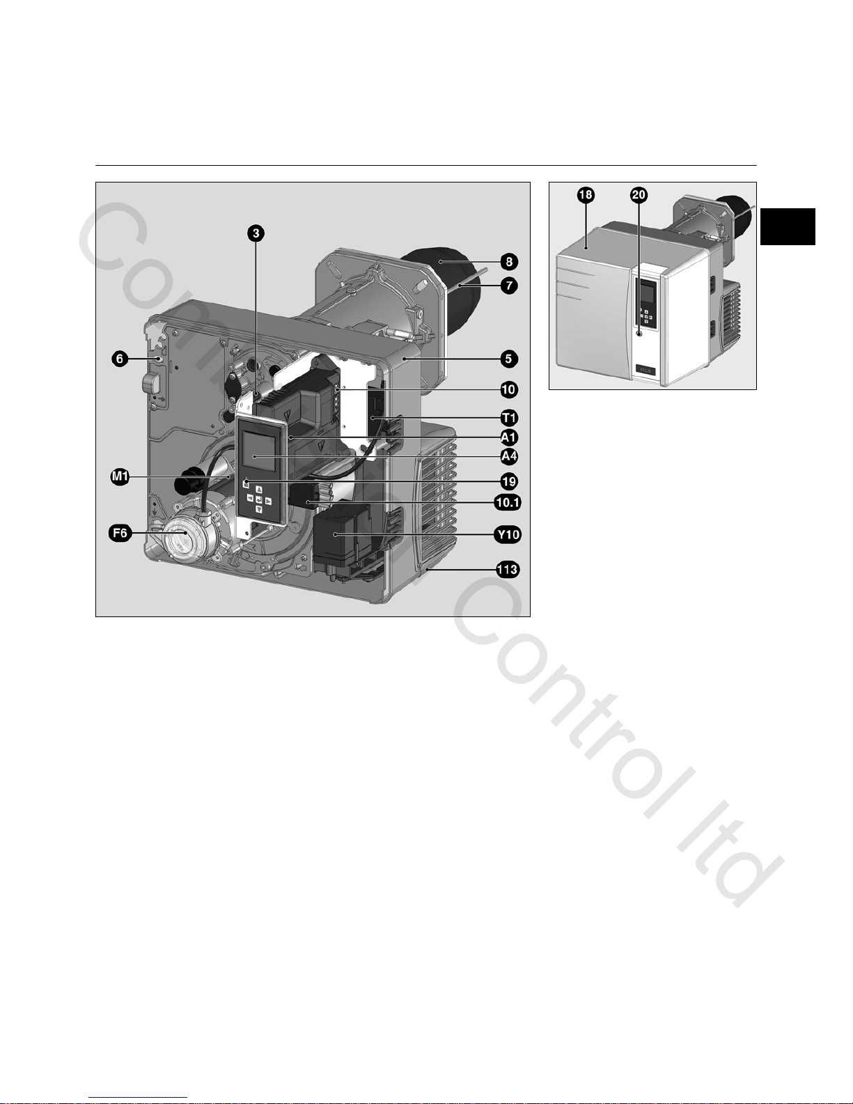
Burner description
A1 Control and safety unit
A4 Display
F6 Air pressure switch
M1 Blower motor
T1 Igniter
Y10 Air flap servomotor
3 Adjusting screw for dimension Y
5 Housing
6 Plate hanging device
(Maintenance)
7 Combustion chamber pressure
take-off pipe
8 Burner tube
10 7-pin connector
10.1 4-pin connector
18 Cover
19 Release knob
20 Hood securing screw
113 Air intake box
en
Combustion Control ltd
Page 4
02/2011 - Art. Nr. 4200 1027 9501B4
Operation
Safety function
Description of the function
A pre-ventilation time of 24 seconds
begins when first powering up, after a
power cut or a lockout, after the gas
supply has been cut or after a shutdown
for 24 hours.
During the pre-ventilation time
- the air pressure is monitored
- the combustion chamber is monitored
to detect any flame signals.
At the end of the pre-ventilation time
- the ignition is switched on
- the main and safety solenoid valves
are opened.
- burner start-up
Monitoring
The flame is monitored by an ionisation
probe. The probe is fitted with insulation
to the gas head and is routed through
the turbulator into the flame zone. The
probe must not have any electrical
contact with earthed parts. The burner
switches to malfunction if a short circuit
occurs between the probe and the
burner earth. During burner operation,
an ionised zone is produced in the gas
flame through which a rectified current
flows from the probe to the burner tip.
The 2
nd
stage ionisation current must be
at least 7 µA.
Safety functions
- If no flame is produced when the
burner is started (gas release), the
burner is switched off at the end of the
safety time which lasts no more than
3 seconds and the gas valve closes.
- If the flame is lost during operation, the
gas supply is cut within a second. A
new start-up sequence is activated. If
the burner starts, the operating cycle
starts running. Otherwise a lockout
occurs.
- If there is an air failure during preventilation or operation, a lockout
occurs.
- If there is a gas failure, the burner
either stops or will not start. As soon
as the gas pressure recovers a
sufficient value, burner starts again.
During the regulator shutdown
- The control thermostat interrupts the
heat request.
- The gas valves close
- The flame goes out
- The burner is ready for operation
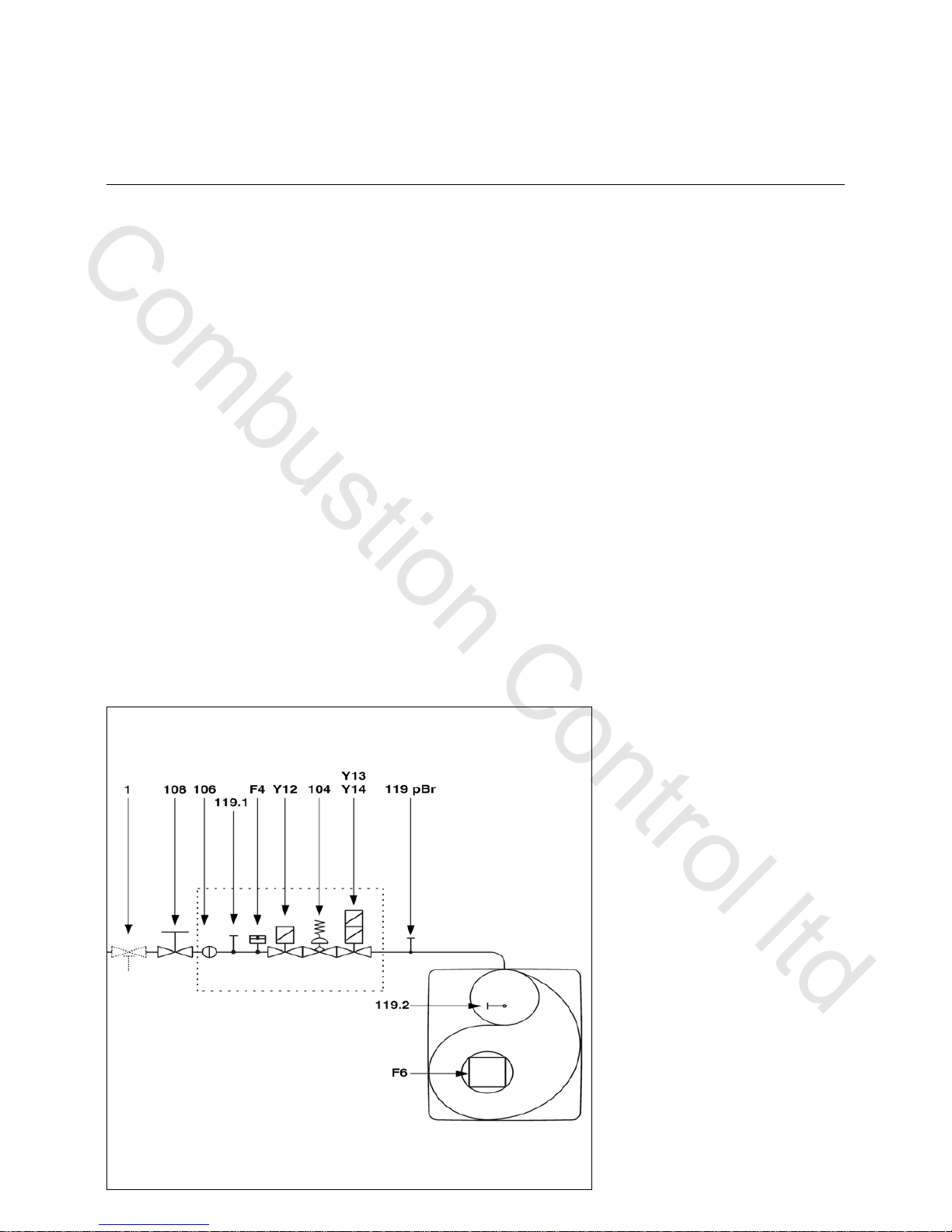
Compact train
CH note
In accordance with SSIGE instructions,
it is compulsory to install a gas safety
valve (mark 1) in the pipe
DE Note
In compliance with the reference layout
applicable to boiler rooms, sites with gas
furnaces must be fitted with a thermal
gas shut-off valve (mark 1).
F4 Gas pressure switch
F6 Air pressure switch
Y12 Safety solenoid valve
Y13 Solenoid valve, 1st stage
Y14 Solenoid valve, 2nd stage
1 Thermal shut-off valve (to be
installed by the installer)
104 Gas pressure regulator
106 Screen
108 Gas cut-out valve (to be installed
by the installer)
119pBrGas pressure measuring point at
the valve outlet
119.1Gas pressure measuring point
upstream of the valves
119.2Air pressure measuring point
Combustion Control ltd
Page 5
02/2011 - Art. Nr. 4200 1027 9501B 5
Operation
TCG 2xx control unit
The TCG 2xx control and safety unit
controls and monitors the forced draught
burner. The microprocessor-controlled
program sequence ensures maximum
stability of time periods, regardless of
fluctuations in the power supply voltage
or the ambient temperature. The
automatic combustion control unit is
designed to cope with brownouts.
Whenever the supply voltage drops
below its rated minimum level (< 185V),
the control unit shuts down - even in the
absence of a malfunction signal. The
control unit switches itself back on again
once the voltage has returned to normal
levels (> 195V).
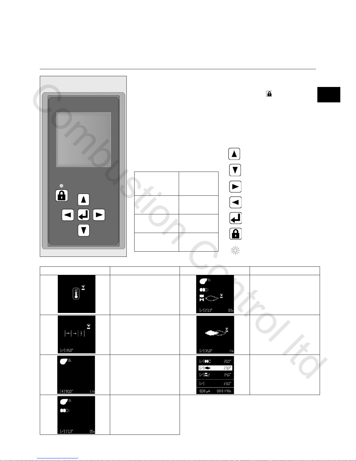
Pressing the
unlocking button on
the unit for
… causes …
... 1 second ... the control unit to
unlock.
... 2 seconds ... the control unit to
lock.
... 9 seconds ... the statistics to
be deleted
Moves the cursor upwards.
Moves the cursor downwards.
Increases the marked value.
Reduces the marked value.
Modifies/Confirms the value
shown.
Unlocks the control unit.
Red LED (flashes if a fault is
present).
Locking and unlocking
The control unit can be locked (switched
to malfunction mode) by pressing the
unlocking button and unlocked (fault
deleted), provided the unit is connected
to the mains power supply.
Always switch off the power
supply before installing or
removing the control unit. Do not
attempt to open or carry out
repairs on the control unit.
Screen Description Screen Description
Awaiting the heat request from
the boiler
Opening the gas valve and
safety time
Air flap is forced open for pre-
ventilation.
Flame is present, awaiting
authorisation of regulation
Pre-ventilation
Burner in operation. The lower
cell shows the strength of the
signal and the operating time of
the burner.
Closing the air flap to the ignition
position, pre-ignition
en
Combustion Control ltd
Page 6
02/2011 - Art. Nr. 4200 1027 9501B6
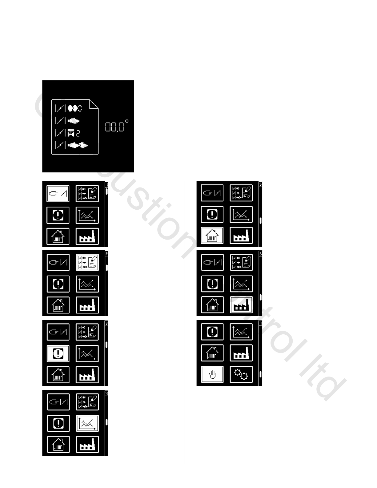
Operation
TCG 2xx control unit
• menu for setting the
servomotor,
• menu for storing the
servomotor setpoints in
the display
• menu for consulting
faults
• menu for statistical data
In parallel with its control and safety
functions, the TCH2xx control unit
allows the following to be set:
(see illustration)
- the position of the air flap during
ignition
- the position of the air flap during the
1st stage
- the opening position of the stage 2
valve (for switching from 1st to 2nd
stage)
- the position of the air flap during the
2nd stage
- the closing position of the stage 2 air
flap (for switching from 2nd to 1st
stage).
The parameters for the control unit are
set using the display and 5 keys.
Operating values are shown in real time
on the display.
Pressing the keys gives access to 7
menus:
(The menu on the bottom right is not
activated in VG3.290 D and VG3.360 D
burners)
• menu for setting/
adjusting the standard
configurations.
• menu for setting
industrial applications
• menu for manual control
In these menus, it is
possible to adjust the
control unit's standard
configurations. These are
pre-set in the factory. No
modifications may be
carried out on-site without
prior consultation with
ELCO. The access code
and the setting setpoints
for this menu are available
on request.
Combustion Control ltd
Page 7
02/2011 - Art. Nr. 4200 1027 9501B 7
Operation
TCG 2xx control unit
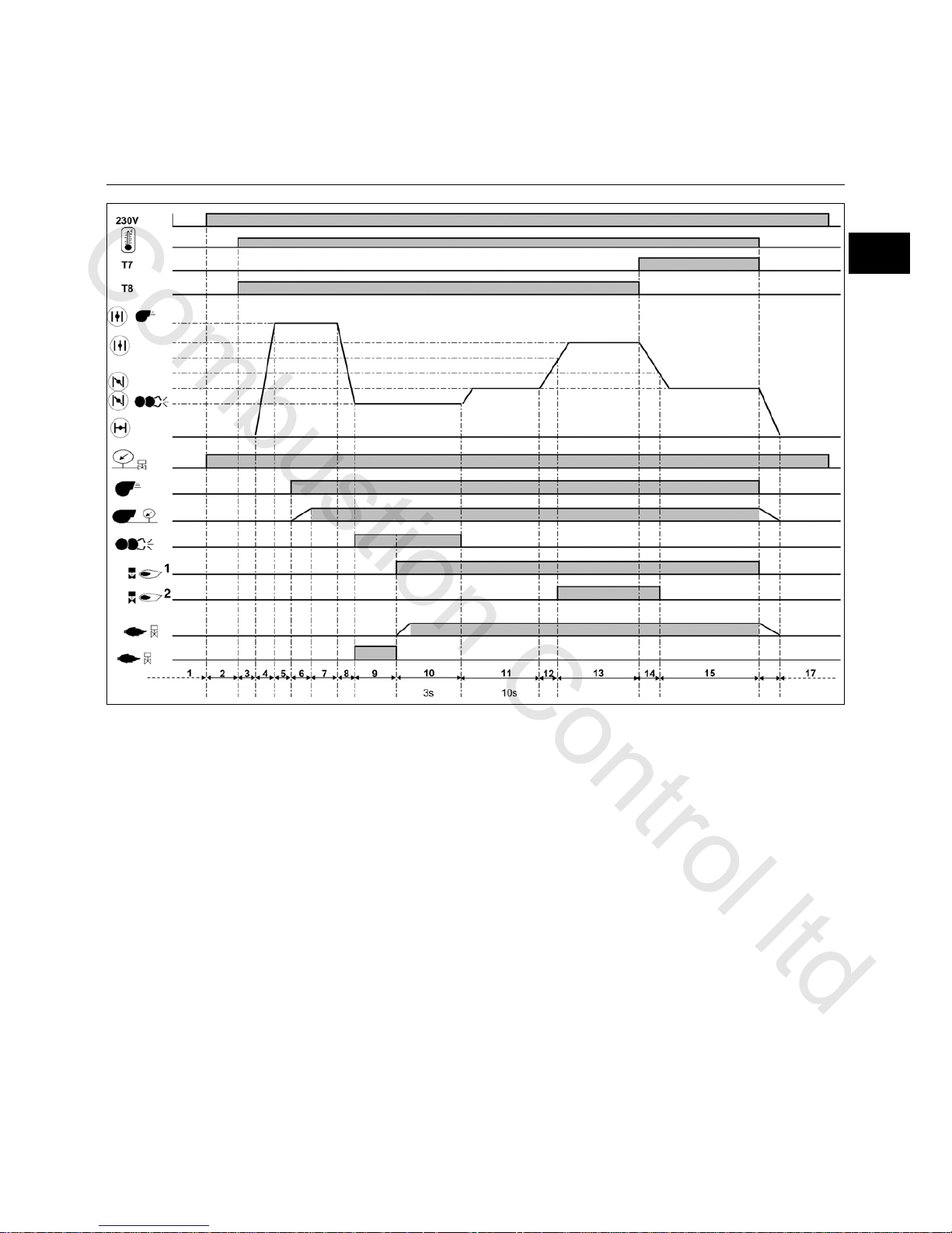
Operating cycle phases:
1: No voltage
2: Powering up, no heat request
3: Checking the air flap is closed
4: Opening an air flap, arrival in pre-
ventilation position
5: Checking the rest status of the air
pressure switch
6: Pre-ventilation: energizing of the
motor, checking the air pressure
7: End of pre-ventilation
8: Air flap closes to the ignition position
9: Switching on the igniter, unauthorised
flame monitoring
10:Starting the burner: Opening of the
solenoid valve, flame formation,
safety time: max. 3 s.
11:Awaiting regulator release
12:Opening the air flap, until the opening
position of the 2
nd
stage valve is
reached
13:Operation in 2
nd
stage
14:Closing the air flap, until the 2
nd
stage valve reaches the closed
position
15:Operation in 1
st
stage
16:Regulator shutdown, closure of the
air flap to 0°
17:Awaiting a new heating request
en
Combustion Control ltd
Page 8
02/2011 - Art. Nr. 4200 1027 9501B8
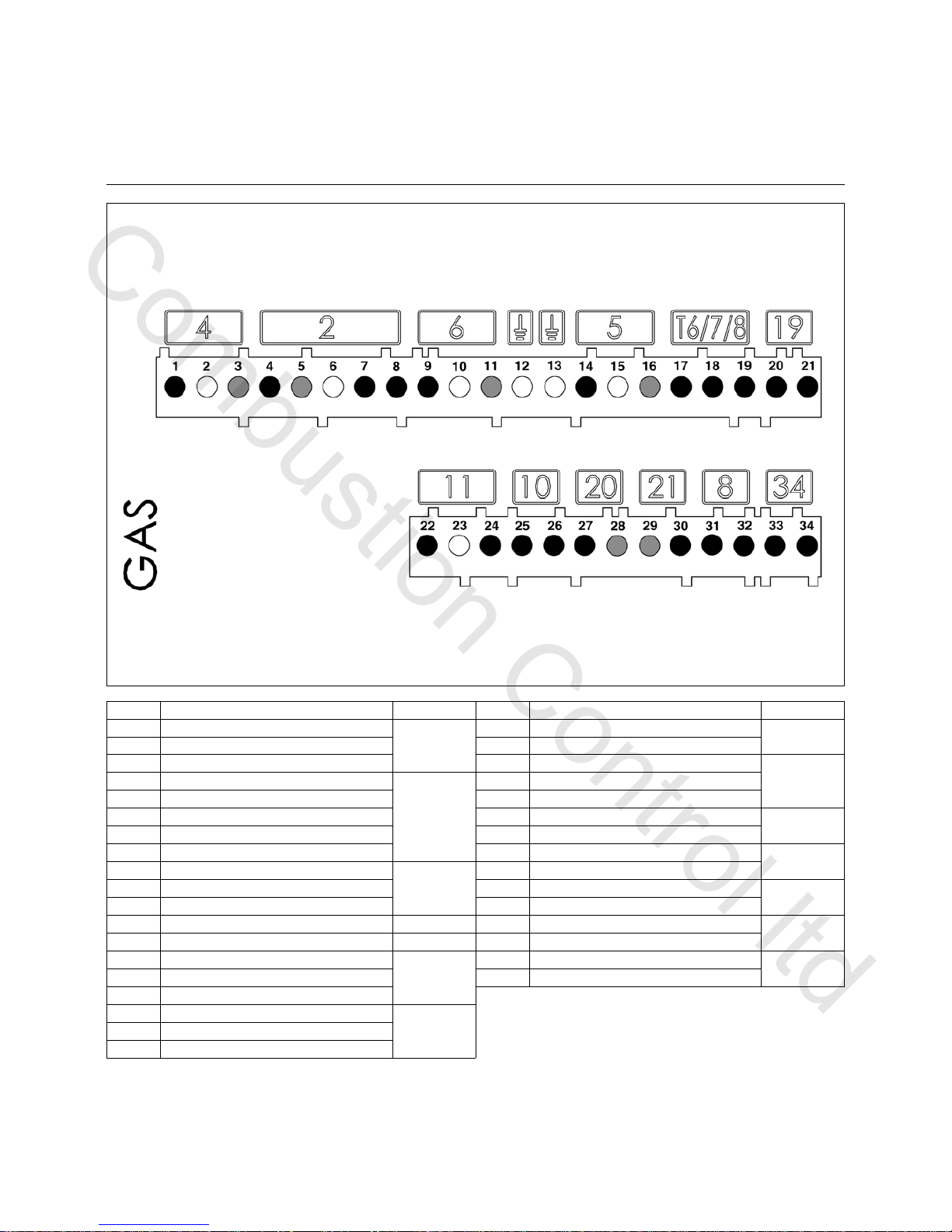
Earth
Flame check
Fault
display
Air
pressure
switch
Igniter
Burner motor
Connector
Terminal
Terminal
Connector
Remote
unlocking
L1 power
supply
Solenoid valve
2nd stage
thermostat
Heating
request
Earth
Gas
pressure
switch
Operation
Terminal allocation chart
230 Volt connection
Terminal Description Connector Terminal Description Connector
1 Burner motor phase
4
20 1st stage thermostat live (T1)
19
2 Earth 21 Heating request signal (option T2)
3 Neutral 22 Flame monitoring signal
11
41st stage solenoid valve live
2
23 Earth
5 Neutral 24 Live
6 Earth 25 Air pressure switch signal
10
7 Live 26 Live
82
nd
stage solenoid valve live 27 Live
20
9 Live L1
6
28 Remote unlocking signal
10 Earth 29 Neutral
21
11 Neutral 30 Signal fault live
12 Earth 31 Live
8
13 Earth 32 Live
14 Igniter live
5
33 Not used
34
15 Earth 34 Not used
16 Neutral
17 Live for the 2
nd
stage thermostat
T6/7/8
18 Signal T7
19 Signal T8
Combustion Control ltd
Page 9
02/2011 - Art. Nr. 4200 1027 9501B 9
Display-PC interface
Air servomotor
Connector
Terminal
Terminal
Connector
Terminal Description Connector Terminal Description Connector
1 not used
30
18 not used
14
2 not used 19 not used
3 not used 20 not used
4 not used
27
28
29
21 not used
5 not used 22 not used
6 not used 23 not used
7 not used 24 not used
33
8 not used 25 not used
9 not used 26 not used
32
10
Display or PC interface
16
/
17
27 not used
11 28
Air servomotor
15
12 29
13 30
14 31
15 32
16 33
17
Operation
Terminal allocation chart
Low voltage connections
en
Combustion Control ltd
Page 10
02/2011 - Art. Nr. 4200 1027 9501B10
Setting the hydraulic brake
Setting the 2nd stage
Setting the 1st stage
Gas pressure
switch
Solenoid valve
coil
Filter ca p
Connecting
flange
Adjusting screw of
the gas pressure
regulator
pBr (4 - 20 mbar)
Locking
screw
Sealed
screw
Operation
MB-ZRDLE gas train
MBZRDLE... B01S.. (dual-stage)
Compact unit consisting of:
filter, adjustable pressure switch, nonadjustable rapid opening and closing
safety valve, adjustable pressure
regulator, main valve (first and second
stage) with adjustable throughput and
hydraulic brake, plus rapid closing.
Default setting:
- Flow rate 1
st
stage and 2nd stage, set
to maximum.
- Ignition flow rate and pressure
regulator set to minimum.
Technical data
Input pressure 360 mbar max.
Ambient temperature -15 to +70 C°
Voltage 230 V/ 50 Hz
Absorbed output 60 VA
Protection level IP 54
Gas connection 3/4" Rp or 1" 1/4 Rp
Assembly position:
- Vertical with coil facing upwards
- Horizontal with coil hidden
Pressure regulator setting
The adjusting screw has a path of 60
turns for adjusting the output pressure.
Three turns clockwise or anticlockwise
increases or reduces pressure by
1 mbar respectively.
At commissioning:
• Turn the screw at least 10 turns
clockwise (+)
• Then fine tune the adjustment (more or
less pressure)
• Checking the gas pressure on the
pressure tap 119pBr.
Setting the ignition throughput
• Unscrew plastic cap B.
• Turn it over and use it as a tool for
turning the adjusting screw (three
turns to adjust from minimum to
maximum throughput)
• Reduce the ignition throughput by
turning the screw clockwise, reduce it
by turning it anti-clockwise.
Adjusting the nominal flow rate
• Unscrew the locking screw (the sealed
screw must not, however, be
unscrewed)
Setting the gas throughput for
the 2
nd
stage
• Reduce nominal gas throughput by
turning adjusting knob C, anticlockwise (located on the upper
section of the solenoid coil). Turning
clockwise increases throughput.
Setting the gas throughput for
the 1
st
stage
By hand (not tool).
• Reduce gas throughput by turning ring
D clockwise (located on the lower
section of the solenoid coil). Turn anticlockwise to increase gas throughput.
Combustion Control ltd
Page 11

02/2011 - Art. Nr. 4200 1027 9501B 11
Assembly
Burner assembly
Ø a Ø b c d
155-190 175-220 M10 45°
Preparing the boiler front
• Prepare the burner mounting plate/
boiler door in accordance with the
diagram.
• Establish the internal diameter a of
155-190 mm.
• To mount the burner head bracket, drill
four M10 holes (drill diameter 175 to
220 mm) as shown in the diagram
opposite.
Burner head assembly
• Screw the bolts into the burner fixing
plate/boiler door and position the
insulation material. For a drill hole of
< 220 mm, elongated slots should be
cut to the required dimensions.
• Remove the combustion components
from the head
• Attach the burner head with 4 nuts (ref.
4). At this point, check that the gas
connection flange is correctly
positioned (on the left or right).
Burner tube installation depth and
brickwork surround
Unless otherwise specified by the boiler
manufacturer, heat generators without a
cooled front wall require brickwork or
insulation 5 as shown in the illustration
opposite. The brickwork must not
protrude beyond the leading edge of the
flame tube, and should have a maximum
conical angle of 60°. Space 6 must be
filled with an elastic, non-flammable
insulation material.
Exhaust gas evacuation system
To avoid unpleasant noise emissions,
right-angled connectors should not be
used on the flue gas side of the boiler.
Fitting the burner body
• Remove the cover (2 screws W).
• Unscrew the two screws on the burner
body completely.
• Bring the burner body into contact after
having swivelled it at least 15° to the
left.
• Engage the two screws Z on the body
into the two lugs provided.
• Tighten the 2 screws.
For assembly in the position with
the volute facing upwards, unclip
the display, turn it over 180°, and
refit it.
On boilers with reverse firing, minimum
flame tube insertion depth A should be
observed as per the boiler
manufacturer's instructions.
en
Combustion Control ltd
Page 12

02/2011 - Art. Nr. 4200 1027 9501B12
Assembly
Gas manifold
Check/adjust the burner head
Checking the burner head
• Check the adjustment settings of the
ionisation probe and of the ignition
electrode as per the diagrams.
Setting to propane gas operation
• Remove the shutter 3 and the
turbulator 4.
• Fit the spacer 5 (supplied with the
burner body).
• Fit the turbulator 4 and the shutter 3.
Gas train assembly
• Check the correct position of the O-
ring B in the gas connecting flange C.
• Secure the gas train on the burner
head so that the gas train coils are in
the upper vertical position.
• Pay attention to the direction of
circulation.
• Connect the power cable to the gas
train.
Check the radial position of the flame
tube
After untightening the three mounting
screws S, it is possible to change the
position of the flame tube using the lever
H. Nitrogen oxide emissions may be
affected by the radial position of the
flame tube.
• Set first on scale value : 1.
Fitting the combustion components
• Check that the O-Ring J1 is in the
correct position in the gas elbow.
• Insert the combustion components
into the head, tighten the mounting
screw X using an Allen key, then
tighten the lock nut using an openended spanner.
• Thread the ionisation cable IK and the
ignition cables ZK into the grommets
R and S.
• Remove the cover.
Combustion Control ltd
Page 13

02/2011 - Art. Nr. 4200 1027 9501B 13
Assembly
Gas connection
Electrical connection
Checks before commissioning
Checks before commissioning
The following must be checked before
initial commissioning:
• That the burner is assembled in
accordance with the instructions given
here.
• That the burner is pre-set in
accordance with the values in the
adjustment table.
• Setting the combustion components.
• The heat generator must be ready for
operation, and the operating
regulations for the heat generator
must be observed.
• All electrical connections must be
correct.
• The heat generator and heating
system must be filled with water and
the circulating pumps must be in
operation.
• The temperature regulator, pressure
regulator, low water detectors and any
other safety or limiting devices that
might be fitted must be connected and
operational.
• The exhaust gas duct must be
unobstructed and the secondary air
system, if available, must be
operational.
• An adequate supply of fresh air must
be guaranteed.
• The heat request must be available.
• Sufficient gas pressure must be
available.
• The fuel supply lines must be
assembled correctly, checked for
leaks and bled.
• A standard-compliant measuring point
must be available, the exhaust gas
duct up to the measuring point must
be free of leaks to prevent anomalies
in the measurement results.
General regulations applying to the
gas connection
• The gas train must only be connected
to the gas mains by a recognised
specialist.
• The cross-section of the gas line
should be of a size designed to
guarantee that the gas flow pressure
does not drop below the specified
level.
• A manual shut-off valve (not supplied)
must be fitted upstream of the gas
train.
• In Germany, a thermally triggered
shut-off valve (to be installed by the
customer side) must be fitted as
specified by the draft combustion
ordinance.
It is the responsibility of the fitter or his
representative to obtain approval for the
system at the same time as the burner is
commissioned. Only the fitter or his
representative can guarantee that the
system meets applicable standards and
regulations. The fitter should be in
possession of the corresponding official
permit, and should carry out the
corresponding sealing tests and purge
the system of air.
Electrical installation and connection
work must only be carried out by a
suitably qualified electrician. All
applicable regulations and directives
must be observed.
The applicable guidelines and
directives must be observed,
as well as the electrical circuit
diagram supplied with the
burner!
Electrical connection
• Check to ensure that the power supply
is as specified (230V, 50 Hz single
phase with neutral and earth)
Boiler fuse: 10 A
Electrical connection
It must be possible to disconnect the
burner from the mains using an
omnipolar shutdown device complying
with the standards in force. The burner
and heat generator (boiler) are
connected by a 7-pin connector 1 and a
4-pin connector 2 (not supplied). The
diameter of the cables connected to
these connectors must be between 8.3
and 11 mm.
Connecting the gas train
Connect the gas train to the plugs on the
burner (black to black, grey to grey).
Ionisation current measurement
To measure the ionisation current,
disconnect connector B10 and connect
a multimeter with a measuring range of
0-100 µA.
The 2
nd
stage ionisation current must be
at least 7 µA. It is also possible to read
the ionisation current on the display.
en
Combustion Control ltd
Page 14

02/2011 - Art. Nr. 4200 1027 9501B14
Commissioning
Adjustment data
Setting the gas pressure switch
• Remove the transparent cover.
• Provisionally set to 15mbar.
Setting the air pressure switch
• Remove the transparent cover.
• Provisionally set to 1 mbar.
MB- ...420
1
st
stage 2nd stage
Ignit .
1st stage 2nd stage
G25 G 20 G25 G20 G25 G31
95 190 40 2
55 29
15 - 1,3 / 5,3 1,6 / 6,3 2 / 6,3 2,3 / 7,7 1,3 / 4,8
140 220 40 2,5 15 15 38 20 - 2,8 / 7 3,3 / 8, 1 4,7 / 8 4, 8 / 10 2,7 / 6,3
190 250 40 2,7
28 28 50
35 - 4,7 / 8,5 6 / 9,8 6,2 / 9 8,3 / 12,3 4,6 / 7,5
125 230 40 2,5 8 8 33 15 2,2 / 7,7 2,5 / 7 2,8 / 8, 3 3 / 8,3 3,8 / 10,5 2,3 / 6,2
180 270 40 3 22 22 48 30 4,4 / 10,7 4 / 9,6 5 / 11,3 5,5 / 11,7 7,1 / 14,7 3,7 / 8,5
240 310 40 3,3 38 38 75 45 8,1 / 13 7,3 / 11, 4 8,7 / 13,5 9,8 / 14,4 12,4 / 18 7,1 / 10,5
VG3.290 D
VG3.360 D
2
d
stage
valve
open ing MB-...4 12 M B-...40 7
Burner power
Dimensi on
Y
(mm )
Furnace
press ure
pF
(mb ar)
Gas val ve setti ng
G as head pres sure pB r (mbar)
1. stage / 2. s tag e
A ir flap s etting
The adjustment values above are guide
values and facilitate commissioning.
The factory settings are in bold set
against a grey background The final
settings are essential in ensuring that
the burner functions as well as possible
Combustion Control ltd
Page 15

02/2011 - Art. Nr. 4200 1027 9501B 15
Commissioning
Air regulation
Air regulation
Combustion air is regulated at two
points:
• on the pressure side, using the gap
between the baffle plate and the
burner tube.
• on the vacuum side, by the air flap
driven by servomotor Y10.
The regulation of air in the burner head
affects not only the air flow but also the
mixing zone and the air pressure in the
burner tube. Turning screw A
- right: more air
- left: less air
• Adjust dimension Y in accordance with
the settings table.
Air regulation by air flap
Air is regulated on the vacuum side by
an air flap. This is driven by servomotor
Y10.
en
Combustion Control ltd
Page 16

02/2011 - Art. Nr. 4200 1027 9501B16
Commissioning
Setting the MB-ZRDLE gas train
General adjustment procedure
The 2
nd
stage can only be adjusted via
the pressure regulator Set the 2
nd
stage
valve (button C) to fully open.
The incremental advance setting on
ignition and on switching stages is
performed using button B.
The 1
st
stage setting is performed using
ring D.
Adjusting the regulator:
The pressure in the regulator is
measured at pBr.
The set pressure supplies the required
flow rate.
Incremental advance setting on
ignition
This hydraulic function affects the gas
valve opening characteristics during
ignition and when switching stages.
• Unscrew plastic cap B.
• Turn it around and use it as a key.
• Turn in the direction of:
arrow to -: the incremental advance
increases
arrow to +: the incremental advance
decreases
Setting the 2
nd
stage using the
adjusting knob C.
This operation is only required when the
burner power is too high with a pressure
of 5 mbar between the valves, or when
the burner is tending to pulse.
Proceed as follows:
• Unscrew the locking screw without
touching the painted screw on the
other side. The cap C is turned 4.5
times.
• Rotate clockwise arrow to -: the flow
is reduced, and vice-versa.
The pressure may need to be corrected.
Adjusting the flow of the 1
st
stage
By hand (not tool).
• Reduce gas throughput by turning ring
D clockwise (located on the lower
section of the solenoid coil). Turn anticlockwise to increase gas throughput.
(there is a difference of 3 whole turns
between the minimum and the
maximum).
Note
Adjusting the gas throughput for the 2
nd
stage may also alter the throughput for
the 1st stage. If this is the case, the 1
st
stage must be readjusted.
• Afterwards, retighten the locking
screw.
Adjusting screw of the
gas pressure
regulator
Locking screw
Sealed screw
Combustion Control ltd
Page 17

02/2011 - Art. Nr. 4200 1027 9501B 17
• For the next step, press any
button.
The overall view of the menus
is displayed, and the air flap
positions settings menu is
selected.
• Open the settings menu by
pressing the button .
You must now enter the
access code (see the label on
the back of the display)
• Increase or decrease the
value in increments by
repeatedly pressing or
.
• When the first figure has
been set, move the cursor to
the right by pressing .
• Repeat the operation until
you reach the last figure.
• Confirm the access code by
pressing
Commissioning
Pre-setting without flame
Setting is carried out in 2 phases:
- pre-adjustment without flame
- setting the flame, to fine tune the
settings based on the combustion
results
When the burner is switched on, the
control unit displays the screen below.
Important
At this point, no setting position for the
servomotor has been defined, therefore
the burner cannot be started under
these conditions.
Modifying a settings value for the servomotor position:
- To modify the value of a position, move the cursor to the
corresponding location with the button or .
- Select the value to be modified using the button , the
selected value will flash.
- Increase or decrease the value in increments of 0.1° by
repeatedly pressing or . For large modifications, press
and hold the button or , the value will scroll quickly up
or down.
- Confirm the new value using the button . The value stops
flashing.
N.B.:
It is possible to set different positions within a large range of
values. However, for safety reasons, the control unit enforces
a minimum interval of 2° between the different positions
(except between the ignition position and the 1
st
stage).
The control unit then opens
the settings mode. The screen
displays the factory presettings for the different
positions of the air flap (here
for example: for a VG3.290 D).
The following positions for the
air flap are presented:
- ignition position (when the
menu is opened, the curser
goes to this position)
- position of the air flap during
the 1
st
stage
- position of the air flap when
the 2
nd
stage fuel oil valve is
opened
- position of the air flap during
the 2
nd
stage
en
Combustion Control ltd
Page 18

02/2011 - Art. Nr. 4200 1027 9501B18
Commissioning
Pre-setting without flame
General advice before starting the burner
End of settings menu without flame
When all the positions of the servomotor have been determined according to the required
settings, it is then possible to move on to the next section for commissioning - "Setting the flame".
To do this, place the cursor in the lower part of the screen on the symbol and confirm by
pressing the button .
If it is necessary to quit the menu without saving the pre-settings, position the cursor on the
symbol and confirm with the button .
Optimising combustion values
Optimum combustion values can be
achieved by adjusting the position of the
baffle plate (dimension Y) if necessary.
Doing this can have an effect on starting
characteristics, pulsation and
combustion values. Any reduction in
dimension Y increases the CO
2
value.
However, starting characteristics
become harsher.
Compensate for the change in airflow if
necessary by adjusting the air flap
position.
Precautions: To avoid condensation,
observe the minimum required flue
gas temperature specified by the
boiler manufacturer and comply with
the requirements for flue gas ducts.
Risk of deflagration
Continuously check CO, CO
2
and soot emissions when
adjusting. Optimise
combustion values if CO is
present. The CO level must
not exceed 50 ppm.
Function check
Flame monitoring must be checked for
safety as part of initial commissioning
and also after servicing or if the system
has been out of operation for any
significant period of time.
- Starting attempt with gas valve closed:
once the safety time has elapsed, the
control and safety unit should indicate
a lack of gas or switch to malfunction
mode.
- Starting with the air pressure switch
closed:
after an 8-second test period, the
burner switches to malfunction mode.
- Starting attempt with air pressure
switch open:
after a 60-second waiting period, the
control and safety unit locks.
- Starting attempt with brief opening of
the air pressure switch during preventilation:
the control and safety unit restarts the
pre-ventilation programme (air
pressure detected again within 60
seconds) ; otherwise a lockout occurs.
Combustion Control ltd
Page 19

02/2011 - Art. Nr. 4200 1027 9501B 19
Commissioning
Setting the flame
- If the boiler heating
request is not present,
the boiler remains on
standby.
In this case, it is still possible
to return to the previous
setting menu "Pre-setting
without flame". To do this,
position the cursor on the
symbol and confirm with
the button .
- If a boiler heating
request is present (T1T2 contact closed), the
burner starts.
The air flap is opened to
move to the pre-ventilation
position.
Air pressure switch test
Pre-ventilation
The air flap switches to the
ignition/pre-ignition position.
The fuel valve opens.
Awaiting flame signal
If no flame is detected at
the end of the safety time,
the control unit switches to
malfunction mode.
Flame detected
Flame stabilisation
The control unit awaits the
regulation authorisation.
en
Combustion Control ltd
Page 20

02/2011 - Art. Nr. 4200 1027 9501B20
Commissioning
Setting the flame
Setting the 1st stage
If the flame has been detected, the control unit sets the burner to the 1st stage as soon as it
receives the regulation authorisation.
- Adjust the gas pressure for the 1
st
stage depending on the required output, using the regulator
on the gas valve. Monitor the combustion values continuously as you do so (CO, CO
2
, soot
test). If necessary, adjust the dimension Y and/or adapt the airflow.
- To do this, modify the position of the servomotor in 1
st
stage. Proceed as described on page
17, in the paragraph "Modifying the value of a servomotor position setting"
- Precautions: when modifying the setting value, the servomotor will move in real time. As a
consequence, the combustion values must be constantly checked.
Specific function: ignition checking
If the ignition position has been modified, it is possible to carry out a new burner start-up to check
the new ignition position, without having to quit the settings menu.
To do this, after modifying the ignition position, position the cursor on the symbol , and initiate
the new start-up using the button .
Setting the opening position of the 2
nd
stage gas valve
After the 1
st
stage is set, it is possible to set the opening value for the 2nd stage gas valve.
Proceed as described in the paragraph "Modifying the value of a servomotor position
setting"
- Precautions: in this case the servomotor does not move immediately, but first remains in the 1
st
stage position (the actual position of the servomotor is always displayed in the lower part of the
display). The 2
nd
stage valve also remains closed.
Setting the 2
nd
stage
To set the position of the air flap in the 2
nd
stage, position the cursor on the corresponding line on
the display using the button .
- To make the burner actually switch to the 2
nd
stage, press the button again. The servomotor
will then move the air flap to the set position. At the same time, the 2
nd
stage gas valve will open,
as soon as the opening position set for the servomotor is passed.
- Adjust the gas pressure for the 2
nd
stage depending on the required output, using the regulator
on the gas valve. Monitor the combustion values continuously as you do so (CO, CO
2
, soot
test). If necessary, adjust the dimension Y and/or adapt the airflow. To do this, modify the
position of the servomotor in the 2
nd
stage. Proceed as described on page 17, in the paragraph
"Modifying the value of a servomotor position setting"
- Precautions: when modifying the setting value, the servomotor will move in real time. As a
consequence, the combustion values must be constantly checked.
Specific function: position the opening and closing of the 2
nd
stage gas valve differently
The control unit has the possibility of setting the opening of the 2
nd
stage valve, when the 1st stage
changes to the 2
nd
stage, at a different position to that for closing when the 2nd stage drops to the
1
st
stage.
- To do this, position the cursor on the symbol and confirm with the button . The selected
symbol will change like this one .
- Using the button , position the cursor on the setting value of the 2
nd
stage gas valve. It is
possible to adjust to different values resp. during 1
st
stage operation the opening position, and
during 2
nd
stage operation the closing position.
Combustion Control ltd
Page 21

02/2011 - Art. Nr. 4200 1027 9501B 21
Closing the "Setting the flame" menu
The burner setting is now complete. If necessary, it is possible to again correct each of the
settings values. To do this, position the cursor on the value to be modified, using the button
or .
Otherwise, at all times, the following possible ways of closing the "Setting the flame" menu are
available:
- Either restart the burner setting procedure, passing through the presetting phase (without
entering a password). To do this, position the cursor on the symbol and confirm with the
button . All the settings values already saved therefore remain available. This is essential for
testing a new ignition position.
- Saving the fixed values and ending the setting procedure. To do this, position the cursor on the
symbol and confirm with the button . The burner is then ready to operate and can now
be controlled by the boiler regulation.
- Quitting the settings menu without reaching the end of the setting procedure. To do this, position
the cursor on the symbol and confirm with the button . All the servomotor positions saved
up to this point are recovered by calling up the settings menu again.
Commissioning
Setting the flame
Operating mode
Operating mode - Display of the operating status, the flame signal and the operating time
After setting of the burner has been completed, it switches to operating mode.
The current operation of the burner (Operation in 1
st
or 2nd stage) is indicated by the cursor.
The lower cell shows the intensity of the signal. The display range is from 0 µA to 7 µA. For the
2
nd
stage, a good quality signal is one above 7µA.
The following limit values are valid:
• When checking an unwanted flame: the signal must be < 0.7µA
• During the safety time: the signal must be > 1.0µA
• During operation: the signal must be > 8µA
The cell at the bottom right displays the current operating time of the burner.
en
Combustion Control ltd
Page 22

02/2011 - Art. Nr. 4200 1027 9501B22
Saving the adjustment values in the display
If the burner setting procedure has been successfully completed,
the servomotor positions for all the operating states will be fixed in
the control unit. It is possible to store a backup copy of the values
in the display.
To do this, press the button , the screen opposite is displayed.
Using the button select the menu "Save adjustment values"
and confirm with the button .
The screen opposite appears. Place the cursor on the symbol ,
press the button to begin loading the adjustment values from
the control unit to the display.
A this point, it is possible to:
- store the values in the display; to do this place the cursor on the
symbol and confirm with button .
- quit the menu without storing the data, with the symbol .
Commissioning
Setting the gas pressure switch
Setting the air pressure switch
Saving the adjustment values in the display
Setting the gas pressure switch
• To set the switch-off pressure: remove
the cover from the gas pressure
switch.
• Install a gas pressure pBr measuring
instrument.
• Start the burner. Switch to 2
nd
stage.
• Reduce the pressure upstream of the
gas train by gradually closing the
manual valve, until
- the gas pressure pBr downstream of
the train drops
- the flame becomes less stable
- the CO level increases
- or the flame signal deteriorates
considerably
• Turn the dial clockwise until the gas
pressure switch shuts down the
burner.
• Continue turning the dial clockwise to
set the gas pressure switch to 10%
above the shutdown value determined
above.
Checking the switch-off pressure
• Open the manual shut-off valve
• Start the burner
• Close the manual shut-off valve
The gas failure procedure should start
without the control unit locking.
Setting the air pressure switch
• Install a pressure measuring device.
To do this, install a T union in the air
tube.
• Start the burner running in the 1
st
stage.
• Set the switch-off point to
approximately 15% below the switchoff pressure read.
Combustion Control ltd
Page 23

02/2011 - Art. Nr. 4200 1027 9501B 23
Servicing
Maintenance
Burner and boiler servicing must only be
carried out by a professionally qualified
heating engineer. The system operator is
advised to take out a maintenance
contract to guarantee regular servicing.
Depending on the type of installation,
shorter maintenance intervals may be
necessary.
• Switch off the power supply before all
maintenance and cleaning work.
• Use original spare parts.
Work recommended as part of annual
burner maintenance:
- Burner test run, input measurement in
the boiler room
- Clean the combustion components
and replace defective parts if
necessary
- Clean the fan wheel and the blower
- Clean the gas filter; replace it if
necessary
- Visual inspection of the burner's
electrical components; eliminate
malfunctions if necessary
- Check burner start characteristics
- Leakage test
- Burner safety devices function check
(air pressure/gas pressure switches)
- Flame monitor and automatic
combustion control unit function check
- Commissioning the burner
- Check the gas flow
- Correct the adjustment values if
necessary
- Draw up a measurement report
General checks
- Emergency stop button function check
- Visual inspection of gas lines in the
boiler room
Checking the combustion
components
• Remove the burner hood.
• Disconnect the ignition cables H on the
igniter side.
• Remove the two screws W from the
cover.
• Remove the combustion components.
• Check the ignition electrodes and the
ignition cables; replace if necessary.
• Clean the baffle plate.
• Check adjustments and settings
during assembly.
Removing the plate
• To do this, unscrew but do not remove
the 2 screws
X
securing the motor plate.
• Turn the plate (bayonet system),
carefully remove it and hang it in the
maintenance position (see
illustration).
• Clean the housing, fan wheel and
recirculation unit, and check that they
are not damaged.
• If necessary to clean it, remove the air
recycler; to do so, remove the screw Z
then unclip it.
• Clean the turbine and check it is not
damaged.
Fitting the fan wheel
When changing the motor or the fan
wheel, refer to the positioning diagram
opposite. The internal flange A of the fan
wheel must be aligned with plate B.
Insert a ruler between the vanes of the
fan wheel and bring A and B to the same
height. Tighten the cone-point screw on
the fan wheel.
en
Combustion Control ltd
Page 24

02/2011 - Art. Nr. 4200 1027 9501B24
Servicing
Maintenance
Replacing the flame tube
For this operation, it is necessary to
either open the furnace gate or remove
the burner.
- Variant 1 - Access via the furnace gate
• Remove the burner head
• Loosen the 3 securing screws S on the
flame tube support by 1 to 2 turns.
(Allen 3).
• Open the combustion chamber door.
• Take out the flame tube, check it,
clean it and, if it is deformed, replace
it.
• Proceed in the reverse order for
refitting.
• Fill in the space between the furnace
gate and the burner tube with fireresistant material.
• Close the furnace gate.
- Variant 2 - Removing the burner
• Remove the burner head.
• Loosen the electrical connections.
• Loosen the burner housing (2 M8
screws) and remove. Do not damage
electrical cables.
• Unscrew the burner head and then
proceed as under variant 1.
• Proceed in the reverse order for
refitting.
The flame tube may be hot
Filter replacement
• The filter element of the multiblock
must be checked at least once a year
and replaced if clogged.
• Loosen the screws of the filter cap on
the multiblock.
• Remove the filter element and clean its
housing.
• Do not use any pressurised cleaning
products.
• Replace the filter element with a new
element.
• Screw the cover back into place.
• Reopen the manual shut-off valve.
• Check it is airtight.
• Check the combustion values.
Cleaning the air box
First check that the air flap is in the
closed position (0°), before
removing it (2 screws V).
• Unscrew the three securing screws T
in the base of the housing by a few
turns.
• Shift the air intake box 113 to the right
to release the screws (bayonet).
• Remove the air intake box, clean it and
refit it in reverse order.
• Check that the air flap and the
servomotor are correctly positioned.
Cleaning the cover
• Do not use abrasive products or
products containing chlorine.
• Clean the cover with water and a
suitable cleaning product.
• Refit the cover.
Precautions
After any operation: check the
combustion performance under real
operating conditions (doors shut,
cover fitted etc.). Record the results
in the relevant documents.
Checking the flue gas temperature
• Check the flue gas temperature at
regular intervals.
• Clean the boiler if the flue gas
temperature is more than 30 °C above
the value measured at the time of
commissioning.
• Use a flue gas temperature gauge to
make the check easier.
Combustion Control ltd
Page 25

02/2011 - Art. Nr. 4200 1027 9501B 25
Servicing
Troubleshooting
Symbol Observation Cause Corrective action
Burner does not start after
thermostatic closure.
No malfunction indicated on the
control and safety unit.
Drop in supply voltage or power
failure.
Control unit malfunction.
Check the cause of the drop in
voltage or the power failure.
Replace the control unit.
No heat requested. Thermostats defective or
incorrectly adjusted
Adjust the thermostats, replace if
necessary.
The burner starts briefly when
switched on, then switches off and
the red indicator light comes on.
The control unit has intentionally
been manually locked.
Unlock the unit.
Burner does not start. Air pressure switch: not in rest
position.
Incorrect adjustment
Contact welded
Readjust the pressure switch.
Check the wiring.
Replace the pressure switch.
Burner does not start.
Gas pressure normal
Insufficient gas pressure.
Gas pressure switch wrongly set or
defective
Check the gas lines.
Clean the filter.
Check the gas pressure switch or
replace the compact gas unit.
Malfunction diagnosis and repair
In the event of a malfunction, first check
that the prerequisites for correct
operation are fulfilled:
1. Is there any current?
2. Is there gas pressure?
3. Is the gas shut-off valve open?
4. Are all control and safety devices,
such as the boiler thermostat, low
water detector, limit switches, etc.
correctly set?
If the fault is still present, check that
each of the burner components is
operating.
Important safety components must not
be repaired; these components must be
replaced by parts with the same part
number.
Only use original spare parts.
Switch off the power supply
before carrying out
maintenance or cleaning.
After any work on the system:
• Under normal operating conditions
(doors closed, cover fitted, etc.),
check combustion and check the
individual lines for leaks.
• Record the results in the relevant
documents.
en
Combustion Control ltd
Page 26

02/2011 - Art. Nr. 4200 1027 9501B26
Symbol Observation Cause Corrective action
Burner blower starts up.
Burner does not start.
Air pressure switch: Contact does
not close.
Readjust the pressure switch.
Check the wiring.
Replace the pressure switch.
Burner blower starts up.
Burner does not start.
Flaring during pre-ventilation or
pre-ignition.
Check the valve. Check flame
monitoring.
The burner starts, the ignition
switches on, then failure
No flame at the end of the safety
time.
Gas throughput set incorrectly.
Malfunction in flame monitoring
system
Incorrect polarisation (live/neutral
position) of the power supply on
the 7P connector/socket
No ignition sparks.
Electrode(s) short-circuited.
Ignition cable(s) damaged or
defective.
Igniter defective.
Control and safety unit
Solenoid valves do not open.
Valves jamming.
Adjust the gas flow stage Check
the condition and position of the
ionisation probe in relation to earth.
Check the condition and
connections of the ionisation circuit
(cables and measurement bridge).
Check that the polarisation of the
7P connector is correct.
Adjust, clean or replace the
electrodes.
Connect or replace the cable(s).
Replace the igniter.
Replace the control unit.
Check the cabling between the
control unit and external
components.
Replace the compact gas unit.
Replace the valves.
The burner switches off during
operation.
Air pressure switch: contact opens
during start-up or during operation.
Flame failure during operation.
Adjust or replace the pressure
switch.
Check the ionisation probe circuit
Check or replace the control and
safety unit.
Servomotor fault Clogging of the air flap
Locking of the air flap
Internal fault with the servomotor
Replace the servomotor
Servicing
Troubleshooting
Combustion Control ltd
Page 27

02/2011 - Art. Nr. 4200 1027 9501B 27
Servicing
Fault diagnosis menu
Operating statistics menu
Fault diagnosis menu
To access the fault diagnosis menu, press any button when the burner is ready to operate, when
the burner is in operation, or when it is in malfunction mode. It is not possible to access the fault
diagnosis menu during the start-up phase.
The general menu screen will appear. Using the buttons , , , or , place the cursor on
the fault diagnosis menu symbol, and confirm using the button .
The details of the last fault to appear are indicated by the flashing symbol. The flame intensity,
network voltage, air flap position, number of burner start-ups as well as the operating time of the
burner at the time it switched to malfunction mode are displayed underneath.
Using the buttons and , it is possible to call up the details of the last 5 faults to have
appeared (the fault number is displayed in the upper left corner of the display). After the details
of the last 5 faults, the telephone number of the after-sales department as well as the
maintenance contract number are shown (no values are entered in the factory).
• Quit the menu using the button
Entering a telephone number for the maintenance company and the maintenance contract
number
When the corresponding symbol appears on the display:
• Keep the button held down until the first figure starts to flash (a short press will exit the
menu).
• Using the buttons or , change the figure to the value required (underscore = empty field)
• Using the button , move on to the next figure.
• When the number is complete, save using the button .
Operating statistics menu
To access the operating statistics menu, press any button, when the burner is ready to operate,
when the burner is in operation, or when it is in malfunction mode. It is impossible to access the
operating statistics diagnosis menu during the start-up phase.
The general menu screen will appear. Using the buttons , , , or , place the cursor on
the operating statistics menu symbol, and confirm using the button .
The operating statistics menu comprises 7 screens. Navigation between the different screens is
done using the buttons and .
- Flame detection time for last start-up
- Average flame detection time for the latest 5 start-ups
- Total number of burner start-ups
- Total number of faults
- Total number of operating hours
- Total number of operating hours in 2
nd
stage
en
Combustion Control ltd
Page 28

02/2011 - Art. Nr. 4200 1027 9501B28
- Total number of burner start-ups since the last meter reset
- Total number of faults since the last meter reset
- Total operating time since the last meter reset
- Total operating time in 2
nd
stage since the last meter reset
Servicing
Operating statistics menu
- Number of "unwanted flame" faults
- Number of "No flame after safety time" faults
- Number of "Flame loss during operation" faults
- Number of "Air pressure switch stuck" faults
- Number of "Air pressure switch does not close during operation" faults
- Number of "Air pressure switch switching over" faults
- Number of "servomotor" faults
• Quit the menu using the button .
Combustion Control ltd
Page 29

02/2011 - Art. Nr. 4200 1027 9501B 29
Combustion Control ltd
Page 30

02/2011 - Art. Nr. 4200 1027 9501B30
Combustion Control ltd
Page 31

02/2011 - Art. Nr. 4200 1027 9501B 31
Combustion Control ltd
Page 32

02/2011 - Art. Nr. 4200 1027 9501B32
Fabriqué en EU. Made in EU.
Document non contractuel. Non contractual document.
www.elco.net
Hotline
ELCO Austria GmbH
Aredst r.16-18
2544 Leobersdorf
0810-400010
ELCO Belgium nv/sa
Z.1 Researchpark 60
1731 Zellik
02-4631902
ELCOTHERM AG
Sarganserstrasse 100
7324 Vilters
0848 808 808
ELCO GmbH
Dreieichstr.10
64546 Mörfelden-Walldorf
0180-3526180
ELCO Italia S.p.A.
Via Roma 64
31023 Resana (TV)
800-087887
ELCO Burners B.V.
Amsterdamsestraatweg 27
1411 AW Naarden
035-6957350
OOO «Ariston Thermo RUS LLC»
Bolshaya Novodmitrovskaya
St.bld.14/1 office 626
127015 Moscow -Russia
+7 495 783 0440
Combustion Control ltd
 Loading...