

Page 1
VG 2.210 V
en
Operating instructions
For specialist installation engineers
Gas burners ........................................... 2-31
de, fr..................................... 4200 1053 2700
it, nl ...................................... 4200 1053 2800
............................................. 4200 1053 2600
09/2013 - Art. Nr. 4200 1053 2900A
Page 2

Overview
Contents
Overview Contents .........................................................................2
Important information .....................................................2
Burner description ..........................................................3
Operation Description of the function, safety functions...................4
Control and safety unit ............................................... 5-7
Terminal allocation chart, connection socket ............. 8-9
MB-VEF gas train .........................................................10
Assembly Burner assembly ..........................................................11
Gas train, pressure take-off pipes ................................12
Checking the mixing unit ..............................................13
Electrical connection, testing before commissioning....... 14
Ionisation current measurement...................................14
Commissioning Adjustment data ........................................................... 15
Air regulation, gas valve adjustment ............................16
Pre-adjustment without flame, general advice
before starting the burner ....................................... 17-18
Setting the flame .................................................... 19-21
Air regulation .......................................................... 22-23
Setting the gas pressure switch, the air pressure switch....... 24
Saving the adjustment values in the display ...............25
Servicing Maintenance .......................................................... 25-26
Troubleshooting...................................................... 27-28
Maintenance / Troubleshooting of the
frequency converter......................................................29
Fault diagnosis menu,
Operating statistics menu ....................................... 30-31
Important information
VG 2.210 V burners are designed for the
low-pollutant combustion of natural gas
and propane gas. The design and
function of the burners meet standard
EN 676. They are suitable for use with
all heat generators complying with
standard EN 303 or for use by hot air
generators complying with standard DIN
4794 or DIN 30697 within their
respective performance range. Any
other type of application requires the
approval of ELCO.
Installation, start-up and maintenance
must only be carried out by authorised
specialists and all applicable guidelines
and regulations must be complied with.
Burner description
VG 2.210 V burners are two-stage fully
automatic monoblock devices. The
special design of the combustion head
enables combustion with low levels of
nitrogen oxide and increased output.
Class 3 type-approval in accordance
with EN676 certifies that the lowest
emission values have been achieved
and means that the national
environmental regulations have been
met
AT: KFA 1995, FAV 1997
CH: LRV 2005
DE: 1.BImSChV
Emissions values may differ, depending
on combustion chamber dimensions,
combustion chamber load and the firing
system (three-pass boilers, boilers with
reverse firing). For specifying warranty
values, the conditions for the measuring
equipment, tolerances and humidity
must be observed.
Packaging
The burner packaging also contains:
1 Gas connection flange
1 Compact gas train with gas filter
1 Burner flange
with insulation
Page
1 Bag containing mounting parts
1 Bag containing Technical
Documentation
The following standards should be
observed in order to ensure safe,
environmentally sound and energyefficient operation:
EN 226
Connection of fuel oil and forceddraught gas burners to a heat generator
EN 60335-1, -2-102
Specification for safety of household
and similar electrical appliances,
particular requirements for gas burning
appliances
Gas lines
When installing the gas lines and trains,
the general directives and guidelines, as
well as the following national
regulations, must be observed:
CH: - G1 instruction text from SSIGE
- EKAS form no. 1942,
liquefied gas directive, part 2
- Cantonal authority guidelines
(e.g. directives for the pilot valve)
DE: - DVGW-TVR/TRGI
Installation location
The burner must not be used in rooms
with aggressive vapours (e.g. hair spray,
tetrachloroethylene, carbon
tetrachloride), high levels of dust or high
air humidity (e.g. laundry rooms).
If no connection to an air exhaust
system is provided for the air supply,
there must be a supply air inlet
measuring:
DE: up to 50 kW: 150 cm
per additional kW: : + 2.0 cm
2
2
CH: QF [kW] x 6= ...cm2; but at least
200 cm2.
Variations may arise as a result of local
regulations.
09/2013 - Art. Nr. 4200 1053 2900A2
We accept no responsibility for
damage arising from:
- inappropriate use.
- incorrect installation and/or repair on
the part of the buyer or any third party,
including the fitting of non-original
parts.
Final delivery and instructions for
use
The firing system fitter must supply the
operator of the system with operating
and maintenance instructions on or
before final delivery. These instructions
should be displayed in a prominent
location at the point of installation of the
heat generator, They should include the
address and telephone number of the
nearest customer service centre.
Notes for the operator
The system should be inspected by a
specialist at least once a year.
Depending on the type of installation,
shorter maintenance intervals may be
necessary! It is advisable to take out a
maintenance contract to guarantee
regular servicing.
Page 3
Overview
en
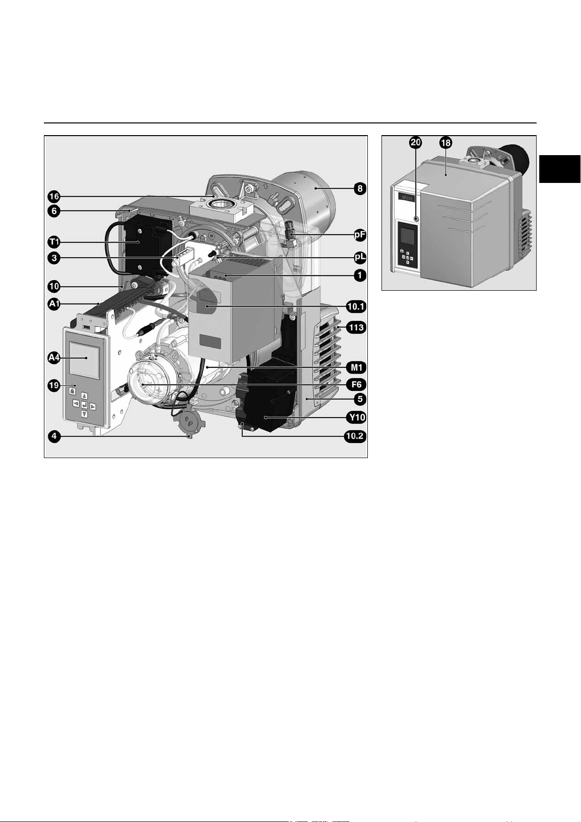
Burner description
A1 Control and safety unit
A4 Display
F6 Air pressure switch
M1 Blower motor
T1 Igniter
Y10 Air flap servomotor
1 Frequency converter for speed
control
3 Adjusting screw for dimension Y
4 Sealing washer for Liquefied
Petroleum Gas
5 Housing
6 Plate hanging device
(Maintenance)
8 Burner tube
10 7-pin connector
10.1 4-pin connector
10.2 3-pin connector (auxiliary motor
supply relay)
16 Gas train connecting flange
18 Cover
19 Release knob
20 Hood securing screw
113 Air intake box
pF Measuring nipple for furnace
pressure
pL Measuring nipple for air
pressure
09/2013 - Art. Nr. 4200 1053 2900A 3
Page 4
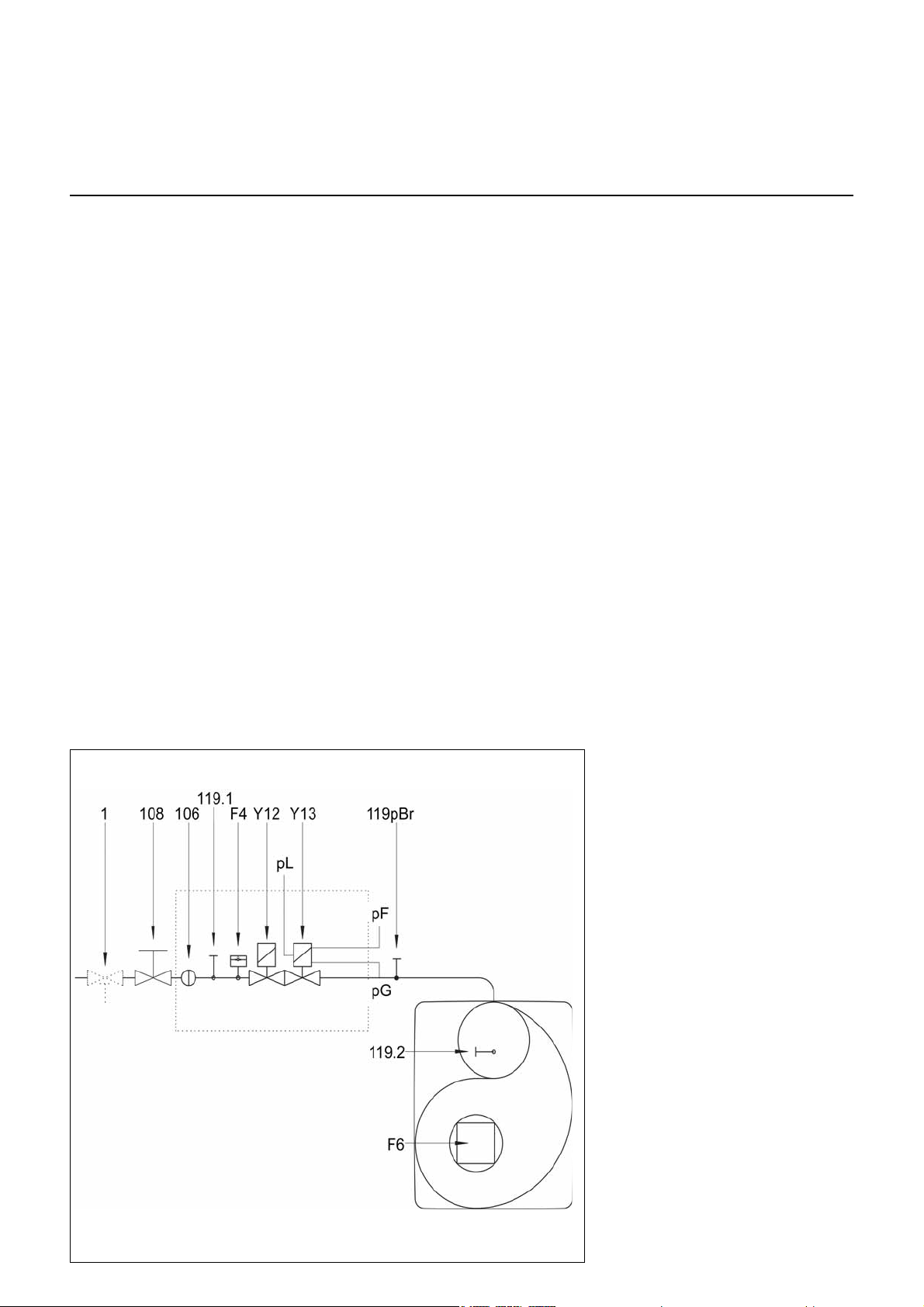
Compact train
Operation
Description of the function
Safety functions
Description of the function
A pre-ventilation time of 24 seconds
begins when first powering up, after a
power cut or a lockout, after the gas
supply has been cut or after a shutdown
for 24 hours.
During the pre-ventilation time
- the air pressure is monitored
- a check is made for the presence of
any abnormal flame signals.
At the end of the pre-ventilation time
- the ignition is switched on
- the main and safety solenoid valves
are opened.
- burner start-up
Monitoring
The flame is monitored by an ionisation
probe. The probe is fitted with insulation
to the gas head and is routed through
the turbulator into the flame zone. The
probe must not have any electrical
contact with earthed parts. The burner
switches to malfunction if a short circuit
occurs between the probe and the
burner earth. During burner operation,
an ionised zone is produced in the gas
flame through which a rectified current
flows from the probe to the burner tip.
The ionisation current must be at least
8µA.
Safety functions
- If no flame is produced when the
burner is started (gas release), the
burner is switched off at the end of the
safety time which lasts no more than
3 seconds and the gas valve closes.
- If the flame is lost during operation, the
gas supply is cut within a second. A
new start-up sequence is activated. If
the burner starts, the operating cycle
starts running. Otherwise a lockout
occurs.
- If there is an air failure during preventilation or operation, a lockout
occurs.
- If there is a gas failure, the burner
either stops or will not start. As soon
as sufficient gas pressure is available
again, the burner restarts.
During the regulator shutdown
- The control thermostat interrupts the
heat request.
- The gas valves close
- The flame goes out
- The blower motor stops
- The burner is ready for operation
F4 Gas pressure switch
F6 Air pressure switch
Y12 Safety solenoid valve
Y13 Main solenoid valve
1 Thermal shut-off valve (to be
installed by the installer)
104 Gas pressure regulator
106 Screen
108 Gas cut-out valve (to be installed
by the installer)
119pBrGas pressure measuring point at
the valve outlet
119.1Gas pressure measuring point
upstream of the valves
119.2Air pressure measuring point
pF Furnace pressure
pG Gas pressure at the head
pL Air pressure
CH note
In accordance with SSIGE instructions,
it is compulsory to install a gas safety
valve (mark 1) in the pipe
DE Note
In compliance with the reference layout
applicable to boiler rooms, sites with gas
furnaces must be fitted with a thermal
gas shut-off valve (1).
09/2013 - Art. Nr. 4200 1053 2900A4
Page 5
en
Operation
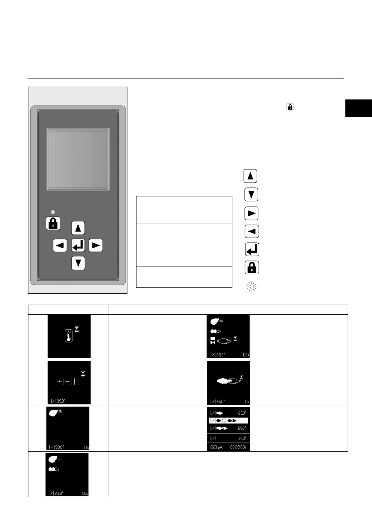
TCG 8xx control unit
The TCG 8xx control and safety unit
controls and monitors the forced draught
burner. The microprocessor-controlled
program sequence ensures maximum
stability of time periods, regardless of
fluctuations in the power supply voltage
or the ambient temperature. The
automatic combustion control unit is
designed to cope with brownouts.
Whenever the supply voltage drops
below its rated minimum level (< 185V),
the control unit shuts down - even in the
absence of a malfunction signal. The
control unit switches itself back on again
once the voltage has returned to normal
levels (> 195V).
Pressing the
unlocking button on
the unit for
... 1 second ... the control unit to
... 2 seconds ... the control unit to
... 9 seconds ... the statistics to
… causes …
unlock.
lock.
be deleted
Locking and unlocking
The control unit can be locked (switched
to malfunction mode) by pressing the
unlocking button and unlocked (fault
deleted), provided the unit is connected
to the mains power supply.
Always switch off the power
supply before installing or
removing the control unit. Do not
attempt to open or carry out
repairs on the control unit.
Moves the cursor upwards.
Moves the cursor downwards.
Increases the marked value.
Reduces the marked value.
Modifies/Confirms the value
shown.
Unlocks the control unit.
Red LED (flashes if a fault is
present).
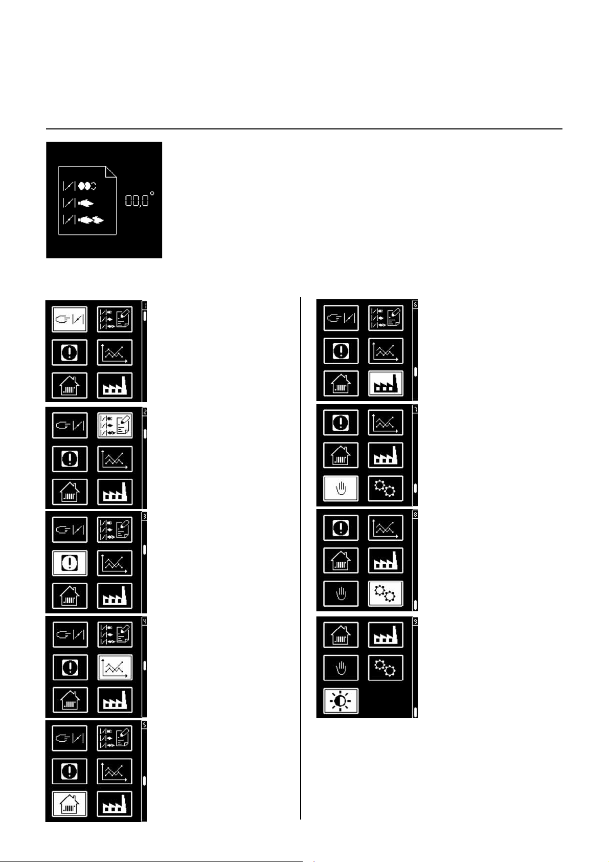
Screen Description Screen Description
Awaiting the heat request from
the boiler
Air flap is forced open for pre-
ventilation.
Pre-ventilation
Closing the air flap to the ignition
position, pre-ignition
Opening the gas valve and
safety time
Flame is present, awaiting
authorisation of regulation
Burner in operation. The lower
cell shows the strength of the
signal and the operating time of
the burner.
09/2013 - Art. Nr. 4200 1053 2900A 5
Page 6
Operation
TCG 8xx control unit
In parallel with its control and safety
functions, the TCG8xx control unit
allows the following to be set:
(see illustration)
- the position of the air flap during
ignition
- the position of the air flap at minimum
pressure
- the position of the air flap at maximum
pressure
• menu for setting the
servomotor
• menu for storing the
servomotor setting
points in the display
The parameters for the control unit are
set using the display and 5 keys.
Operating values are shown in real time
on the display.
Pressing the keys gives access to 9
menus:
• menu for setting
industrial applications*
• menu for manual control*
• fault diagnosis menu
• operating statistics
menu
• menu for setting/
adjusting the standard
configurations*
• Parameter mode menu*
• Menu for adjusting
screen contrast and
brightness settings
* In these menus, it is
possible to adjust the
control unit's standard
configurations. These
are pre-set in the
factory. No
modifications may be
carried out on-site
without prior
consultation with ELCO.
The access code and
the setting setpoints for
these menus are
available on request.
09/2013 - Art. Nr. 4200 1053 2900A6
Page 7
en
Operation
TCG 8xx control unit
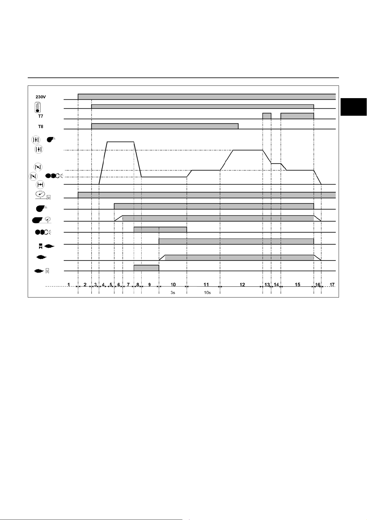
Operating cycle phases:
1: No voltage
2: Powering up, no heat request
3: Heating request
4: Opening an air flap, arrival in pre-
ventilation position
5: Checking the rest status of the air
pressure switch
6: Pre-ventilation: energizing of the
motor, checking the air pressure
7: Pre-ventilation
8: Air flap closes to the ignition position
9: Switching on the igniter, unauthorised
flame monitoring
10:Opening of the solenoid valve, flame
formation, safety time: max. 3 s.
11:Awaiting regulator release
12:Opening the air flap, until the
maximum output is reached
13:Closing of the air flap until the
minimum regulation position is
reached
14:Operation at intermediate regulation
power
15:Operation at minimum regulation
power
16:Regulator shutdown, closure of the
air flap
17:Awaiting a new heating request
09/2013 - Art. Nr. 4200 1053 2900A 7
Page 8
Operation
Earth
Flame check
Fault
display
Air pressure
switch
Igniter
Burner motor
Connector
Terminal
Terminal
Connector
Remote
unlocking
L1 power
supply
Solenoid valve
Control
thermostat
Heating
request
Earth
Gas pressure
switch
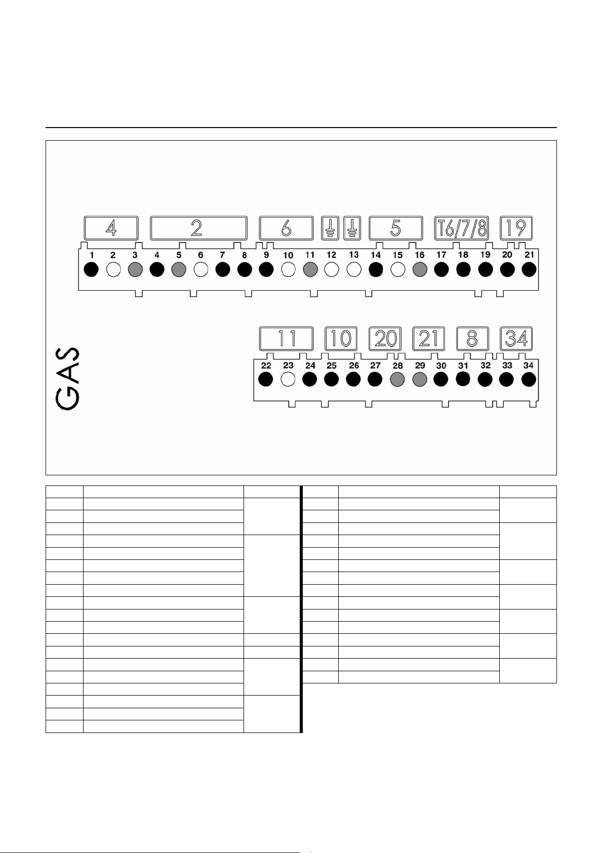
Terminal allocation chart
230 Volt connection
Terminal Description Connector Terminal Description Connector
1 Burner motor live
2 Earth 21 Heating request signal (option T2)
3 Neutral 22 Flame monitoring signal
5 Neutral 24 Live
6 Earth 25 Air pressure switch signal
7 Solenoid valve live 26 Live
8 Live 27 Live
9 Live L1
10 Earth 29 Neutral
11 Neutral 30 Signal fault live
12 Earth 31 Live
13 Earth 32 Live
14 Igniter live
15 Earth 34 Not used
16 Neutral
17 Control thermostat live
18 Signal T7
19 Signal T8
4
2
6
5
T6/7/8
20 Minimum output thermostat live (T1)
23 Earth
28 Remote unlocking signal
33 Not used
34
19
114 Solenoid valve live
10
20
21
8
09/2013 - Art. Nr. 4200 1053 2900A8
Page 9

en
Operation
Display-PC interface
Air servomotor
Connector
Terminal
Terminal
Connector
Speed converter
Terminal allocation chart
Low voltage connections
Terminal Description Connector Terminal Description Connector
1 not used
2 not used 19 not used
3 not used 20 not used
4 not used
5 not used 22 not used
6 not used 23 not used
7 not used 24 not used
8 not used 25 not used
9 not used 26
10
11 28
12 29
13 30
Display or PC interface
14 31
15 32
16 33
17
30
27
28
29
16
17
/
18 not used
21 not used
27
Speed converter
Air servomotor
14
33
32
15
09/2013 - Art. Nr. 4200 1053 2900A 9
Page 10
Operation
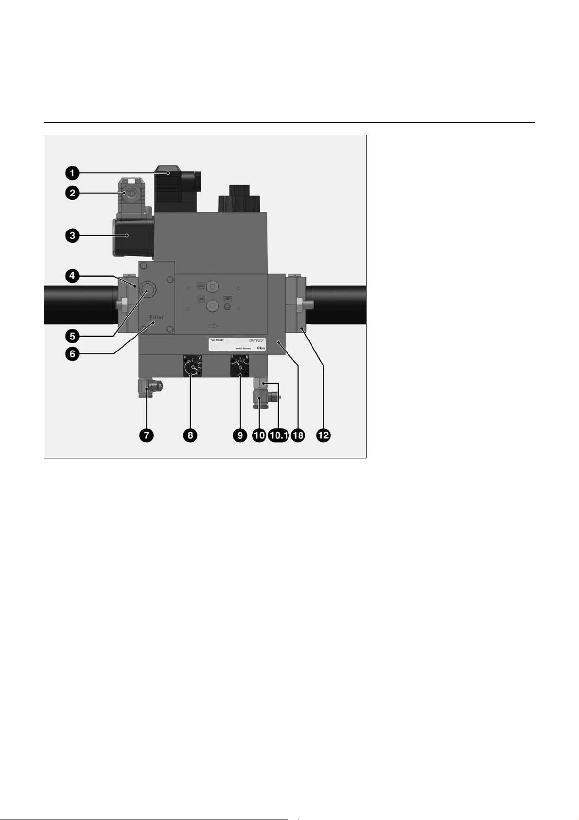
MB-VEF gas train
1 Electrical connection of solenoid
valves (DIN 43650)
2 Electrical connection of the
gas pressure switch (DIN 43650)
3 Gas pressure switch
4 Inlet flange
5 Pressure measuring nipple
R1/8, upstream of filter (option)
6 Filter (under the cover)
7 Connection for furnace pressure
release pipe pF, R1/8
8 Adjusting screw for V ratio
9 Adjusting screw for zero point
offset N
10 Connection for pressure pipe pL,
R1/8
10.1 Nozzle Ø0.4 mm to be fitted
according to applications between
pL and the valve
12 Outlet flange
18 Impulse flange
The MBVEF compact gas valve
assembly is a combination of filter, gas/
air ratio regulator, valves and a pressure
switch:
- Screen with 0.8mm mesh
- GWA5 pressure switch
- Servo-pressure control part with
adjustable ratio V, correction of the
zero point offset N and furnace
pressure connection.
- V1 and V2 fast-opening and closing
solenoid valves
Technical data
Input pressure 360 mbar max.
Ambient temperature -15 to +70°C
Voltage 230 V/ 50 Hz Max.
Absorbed output 50 VA
Protection rating IP 21
09/2013 - Art. Nr. 4200 1053 2900A10
Page 11

Assembly
en
Burner assembly
Burner assembly
Burner flange 3 is equipped with
elongated holes and can be used with a
hole circle diameter of 150 - 184mm.
These dimensions comply with EN 226.
Sliding pipe bracket 2 on the burner pipe
makes it possible to adjust the installed
depth of the mixing unit to the geometry
of the combustion chamber concerned.
The installed depth remains the same
during fitting and removal.
Pipe bracket 2 secures the burner to the
connecting flange and therefore to the
boiler. This completely seals off the
combustion chamber.
Caution : do not block the burner
pressure the pF.
Installation:
• Secure connecting flange 3 to the
boiler using screws 4
• Fit pipe bracket 2 to the burner pipe
and secure using screw 1. Tighten
screw 1 to a maximum torque of 6 Nm.
• Turn the burner slightly, guide it into
the flange and secure using screw 5.
Removal:
• Loosen screw 5
• Turn the burner out of the bayonet
socket and pull it out of the flange.
Burner tube installation depth and
brickwork surround
Unless otherwise specified by the boiler
manufacturer, heat generators without a
cooled front wall require brickwork or
insulation 5 as shown in the illustration
opposite. The brickwork must not
protrude beyond the leading edge of the
flame tube, and should have a maximum
conical angle of 60°. Space 6 must be
filled with an elastic, non-flammable
insulation material.
DOn boilers with reverse firing, minimum
flame tube insertion depth A should be
observed as per the boiler
manufacturer's instructions.
Inspection glass cooling
The burner housing can be equipped
with an R1/8" connection to support a
line for cooling the inspection glass of
the boiler.
• To do this, drill through boss 6 and cut
an 1/8" thread.
• Use accessories article No.
12 056 459 for the connecting nipple
and connection hose.
For assembly in the position with
the volute facing upwards, unclip
the display, turn it over 180°, and
refit it.
Exhaust gas evacuation system
To avoid unpleasant noise emissions,
right-angled connectors should not be
used on the flue gas side of the boiler.
09/2013 - Art. Nr. 4200 1053 2900A 11
Page 12

Assembly
Gas train
Pressure take-off pipes
Gas train assembly
• Check the correct position of the
O-ring J1 in the gas connecting
flange.
• Secure the gas train on the burner
head so that the gas train coils are in
the upper vertical position.
• Pay attention to the direction of
circulation.
• Route the connection cable for the gas
train through clamp 7 and connect it to
the gas train.
On burners VG 2.210 V, fit the
restricting piece 2 (comes with gas
train fittings bag, with the burner
flange.
Connecting pressure take-off pipes
pF and pL
• Release cable clamp 9.
• Insert the two C cables and the PL
pressure release cable into the cable
camp.
• Connect the furnace pressure take-off
pL on the mixing unit cover and the
union pL on the gas train using the
flexible tube pL (blue), shorten the
tube depending on the assembly
scenario.
• Connect the furnace pressure take-off
pF on the burner blast tube and the
union pF on the gas train using the
flexible tube pF (grey), shorten the
tube depending on the assembly
scenario.
• Manually screw in the unions (max.
5 Nm) and check tightness.
If pulsations are observed when
the burner is operating, fit the
nozzle Ø 0.4 (comes with the
burner) between connection pL
and the valve.
09/2013 - Art. Nr. 4200 1053 2900A12
Page 13

Assembly
en
VG 2.120
Checking the mixing unit
Checking the mixing unit
• Loosen the three cover screws W.
• Remove the cover.
• Loosen lock nut E on the gas pipe
bracket
• Loosen the retaining bolt.
• Remove the mixing unit.
Setting to liquid gas operation
• Remove stabilising stop 3 and baffle
plate 4.
• Fit adaptor 5 (supplied with the
housing).
• Refit baffle plate 4 and stabilising stop
3.
Checking the mixing unit
• Check the adjustment of the ionisation
sensor and the ignition electrode in
accordance with the illustrations.
09/2013 - Art. Nr. 4200 1053 2900A 13
Page 14

Assembly
Electrical connection
Checks before commissioning
Ionisation current measurement
General regulations applying to the
gas connection
• The gas train must only be connected
to the gas mains by a recognised
specialist.
• The cross-section of the gas line
should be of a size designed to
guarantee that the gas flow pressure
does not drop below the specified
level.
• A manual shut-off valve (not supplied)
must be fitted upstream of the gas
train.
• In Germany, a thermally triggered
shut-off valve (to be installed by the
customer side) must be fitted as
All electrical installation and
connection work must only be carried
out by a suitably qualified electrician.
The applicable guidelines and
directives must be observed, as well
as the electrical circuit diagram
supplied with the burner!
Electrical connection
• Check to ensure that the power supply
is as specified (230V, 50 Hz single
phase with neutral and earth)
Boiler fuse: 6.3 A
specified by the draft combustion
ordinance.
It is the responsibility of the fitter or his
representative to obtain approval for the
system at the same time as the burner is
commissioned. Only the fitter or his
representative can guarantee that the
system meets applicable standards and
regulations. The fitter should be in
possession of the corresponding official
permit, and should carry out the
corresponding sealing tests and purge
the system of air.
The burner motor has its own
separate power supply (no. 3).
Fuse on the motor circuit: 6 A gM
Electrical connection
It must be possible to disconnect
the burner from the mains using an
omnipolar shutdown device
complying with the standards in
force. The burner and heat
generator (boiler) are connected
by a 7-pin connector 1 and a 4-pin
connector 2 (not supplied). The
diameter of the cables connected
to these connectors must be
between 8.3 and 11 mm.
Connecting the gas train
Connect the gas train to the plugs on the
burner (black to black, grey to grey).
Checks before commissioning
The following must be checked before
initial commissioning:
• That the burner is assembled in
accordance with the instructions given
here.
• That the burner is pre-set in
accordance with the values in the
adjustment table.
• Setting the combustion components.
• The heat generator must be ready for
operation, and the operating
regulations for the heat generator
must be observed.
• All electrical connections must be
correct.
• The heat generator and heating
system must be filled with water and
the circulating pumps must be in
operation.
• The temperature regulator, pressure
regulator, low water detectors and any
other safety or limiting devices that
might be fitted must be connected and
operational.
• The exhaust gas duct must be
unobstructed and the secondary air
system, if available, must be
operational.
• An adequate supply of fresh air must
be guaranteed.
• The heat request must be available.
• Sufficient gas pressure must be
available.
Ionisation current measurement
To measure the ionisation current,
disconnect connector B10 and connect
a multimeter with a measuring range of
0-100 µA.
The ionisation current must be at least
8 µA. It is also possible to read the
ionisation current on the display.
• The fuel supply lines must be
assembled correctly, checked for
leaks and bled.
• A standard-compliant measuring point
must be available, the exhaust gas
duct up to the measuring point must
be free of leaks to prevent anomalies
in the measurement results.
09/2013 - Art. Nr. 4200 1053 2900A14
Page 15

Commissioning
en
Mini. Maxi. Ignition Mini. Maxi. LL UL G20 G25 G20 G25
150 20 35 25 60 25
50 -
-2 / -1 -
170 25*/35** 30 25 90 25 50 2,5 / -1 2,5 / -1
2,5 / 0
2,5 / 0
210 35 40 30 90 25 50 2,5 / -2 - 2,25 / -0,5 -
* : p=300mbar; ** : p=20 mbar
VG 2.210V
Air flap setting
Parameter
Burner
power
Frequency converter
setting
Gas valve setting
Screw V / Screw N
MB-VEF407
80
Y
(mm) MB-VEF412
Adjustment data
Dimension
The adjustment values above are
guide values and facilitate
commissioning. The factory settings are
in bold set against a grey background
The final settings are essential in
ensuring that the burner functions as
well as possible
Setting the gas pressure switch
• Remove the transparent cover.
• Provisionally set to 15mbar.
Setting the air pressure switch
• Remove the transparent cover.
• Provisionally set to 1 mbar.
09/2013 - Art. Nr. 4200 1053 2900A 15
Page 16

Commissioning
Air regulation
Gas valve adjustment
The combustion air is regulated via
three parameters:
• On the pressure side by means of the
opening gap between the turbulator
and burner tube.
• On the suction side by means of the air
flap actuated by servomotor Y10.
• Air regulated by fan speed, setting via
frequency converter.
The regulation of air in the burner head
affects not only the air flow but also the
mixing zone and the air pressure in the
burner tube. Turning screw A
- right: more air
- left: less air
• Adjust dimension Y in accordance with
the settings table.
Air regulation by air flap
Air is regulated on the vacuum side by
an air flap. This is driven by servomotor
Y10.
Gas valve adjustment
V Setting the maximum power
N Setting the minimum power
- For more CO
scale.
- For less CO
scale.
turn upwards on the
2
turn downwards on the
2
09/2013 - Art. Nr. 4200 1053 2900A16
Page 17

en
Commissioning
Pre-setting without flame
Setting is carried out in 2 phases:
- pre-adjustment without flame
- setting the flame, to fine tune the
settings based on the combustion
results
When the burner is switched on, the
control unit displays the screen below.
• For the next step, press any
button.
Important
At this point, no setting position for the
servomotor has been defined, therefore
the burner cannot be started under
these conditions.
The control unit then opens
the settings mode. The screen
displays the factory presettings for the different
positions of the air flap (here
for example: for a VG 2.210
V).
The following positions for the
air flap are presented:
The overall view of the menus
is displayed, and the air flap
positions settings menu is
selected.
• Open the settings menu by
pressing the key.
You must now enter the
access code (see the label on
the back of the display)
• Increase or decrease the
value in increments by
repeatedly pressing or
.
• When the first figure has
been set, move the cursor to
the right by pressing .
• Repeat the operation until
you reach the last figure.
• Confirm the access code by
pressing
- ignition position (when the
menu is opened, the curser
goes to this position)
- the position of the air flap at
minimum pressure
- the position of the air flap at
maximum pressure
Modifying a settings value for the servomotor position:
- To modify the value of a position, move the cursor to the
corresponding location with the or key.
- Select the value to be modified using the key, the
selected value will flash.
- Increase or decrease the value in increments of 0.1° by
repeatedly pressing or . For large modifications, press
and hold the or key the value will scroll quickly up or
down.
- Confirm the new value using the key. The value stops
flashing.
09/2013 - Art. Nr. 4200 1053 2900A 17
Page 18

Commissioning
Pre-setting without flame
General advice before starting the burner
End of presetting menu without flame
When all the positions of the servomotor have been determined according to the required
settings, it is then possible to move on to the next section for commissioning - "Setting the flame".
To do this, place the cursor in the lower part of the screen on the symbol and confirm by
pressing the key.
If it is necessary to quit the menu without saving the pre-settings, position the cursor on the
symbol and confirm with the key.
Optimising combustion values
Optimum combustion values can be
achieved by adjusting the position of the
turbulator (dimension Y) if necessary.
Doing this can have an effect on starting
characteristics, pulsation and
combustion values. Any reduction in
dimension Y increases the CO
However, starting characteristics
become harsher.
Compensate for the change in airflow if
necessary by adjusting the air flap
position.
Precautions: To avoid condensation,
observe the minimum required flue
gas temperature specified by the
boiler manufacturer and comply with
the requirements for flue gas ducts.
Risk of deflagration
Continuously check CO, CO
and soot emissions when
adjusting. Optimise
combustion values if CO is
present. The CO level must
not exceed 50 ppm.
value.
2
2
Function check
Flame monitoring must be checked for
safety as part of initial commissioning
and also after servicing or if the system
has been out of operation for any
significant period of time.
- Starting attempt with gas valve closed:
once the safety time has elapsed, the
control and safety unit should indicate
a lack of gas or switch to malfunction
mode.
- Starting with the air pressure switch
closed:
after an 8-second test period, the
burner switches to malfunction mode.
- Starting attempt with air pressure
switch open:
after a 60-second waiting period, the
control and safety unit locks.
- Starting attempt with brief opening of
the air pressure switch during preventilation:
the control and safety unit restarts the
pre-ventilation programme (air
pressure detected again within
60 seconds) ; otherwise a lockout
occurs.
09/2013 - Art. Nr. 4200 1053 2900A18
Page 19

en
Commissioning
Setting the flame
- If the boiler heating request
is not present, the boiler
remains on standby.
In this case, it is still possible to
return to the previous setting
menu "Pre-setting without
flame". To do this, position the
cursor on the symbol and
confirm with the key.
- If a boiler heating request is
present (T1-T2 contact
closed), the burner starts.
The air flap is opened to move
to the pre-ventilation position.
Air pressure switch test
The air flap switches to the
ignition/pre-ignition position.
The fuel valve opens.
Awaiting flame signal
If no flame is detected at the
end of the safety time, the
control unit switches to
malfunction mode.
Pre-ventilation
If the flame is detected
Flame stabilisation
The control unit awaits the
regulation authorisation.
09/2013 - Art. Nr. 4200 1053 2900A 19
Page 20

Commissioning
Setting the flame
Setting the minimum pressure
If the flame has been detected and stabilised, the control unit sets the burner to minimum power
as soon as it receives the regulation authorisation.
- Check the combustion values (CO, CO
(see page16).
- Read the ionisation current value.
- Read the gas flow rate on the gas counter.
Modification of the air flow via the "manual output control"
The "manual output control" function allows the burner output to be modified.
To do this, position the cursor on the corresponding line on the display and confirm with the
key. It is then possible to adjust the burner output upwards or downwards using the , keys.
The servomotor reacts in real time. This is why the combustion values must be continuously
monitored.
Where required, correct the burner power through the fan speed (UL parameter) and/or by the
opening of the air flap.
Precautions: The fan speed must not go below 30 Hz at partial load (value read on the
display of the converter).
, soot test). If necessary, adjust screw N on the valve
2
Setting the maximum output
Slowly increase the burner to the maximum output using the "manual power control" function. At
this point, adjust the gas flow using the regulator V on the gas train.
The preset limit values for the minimum output and the maximum output cannot be exceeded. If
necessary, exit the "manual output control" function again using the key and modify the limit
value for the maximum or minimum output.
Where required, correct the burner power through the fan speed (LL parameter) and/or by the
opening of the air flap.
Precautions: The fan speed must not exceed 50 Hz at full load (value read on the display).
Definitive limitation of the maximum output position
Limit the maximum opening of the air flap according to the position determined for the maximum
output. In this example, the new position determined for the maximum output is below the value
set manually. Using the "manual output control" function, it is now possible to reduce the burner
output, but this cannot be set above the new maximum position, which here is 50°.
Definitive limitation of the minimum output position
Using the "manual output control" function, reduce the burner output to the minimum output. If
necessary, limit the minimum output position, in the same way as for the maximum output.
Specific function: ignition checking
If the ignition position has been modified, it is possible to carry out a new burner start-up to check
the new ignition position, without having to quit the settings menu.
To do this, after modifying the ignition position, position the cursor on the symbol, and initiate
the new start-up using the key.
09/2013 - Art. Nr. 4200 1053 2900A20
Page 21

en
Commissioning
Setting the flame
Operating mode
Closing the "Setting the flame" menu
The burner setting is now complete. If necessary, it is possible to again correct each of the
settings values. To do this, position the cursor on the value to be modified, using the or key.
Otherwise, at any point, there are 3 possible ways of closing the "Setting the flame" menu, as
follows:
- either restart the burner setting procedure, passing through the presetting phase (without
entering a password). To do this, position the cursor on the symbol and confirm with
the key. All the settings values already saved therefore remain available. This is essential
for testing a new ignition position.
- or: Save the fixed values and end the setting procedure. To do this, position the cursor on the
symbol and confirm with the key . The burner is then ready to operate and can now be
controlled by the boiler regulation.
- or: Quit the settings menu without reaching the end of the setting procedure. To do this, position
the cursor on the symbol and confirm with the key . All the servomotor positions saved
up to this point are recovered by calling up the settings menu again.
Pulsations optimisation
If some pulsations are observed , due to furnace or chimney configurations, it is possible to
change valve operation behaviour by fitting the nozzle D on the valve, between pL fitting and the
pressure take-off tube.
Operating mode - Display of the operating status, the flame signal and the operating time
After setting of the burner has been completed, it switches to operating mode.
The burner's instantaneous operating status (operation at minimum or maximum power) is shown
by the cursor.
The lower cell shows the intensity of the signal. The display range is from 0 µA to 7 µA. A good
quality signal is above 7 µA.
The following limit values are valid:
• When checking an unwanted flame: the signal must be < 0.7 µA
• During the safety time: the signal must be > 1.0 µA
• During operation: the signal must be > 0.9 µA
The cell at the bottom right displays the current operating time of the burner.
09/2013 - Art. Nr. 4200 1053 2900A 21
Page 22

Commissioning
Air regulation
Air regulated via frequency converter
The fan speed is controlled via the
frequency converter, depending on the
position of the air damper. The minimum
and maximum fan speed are set via the
LL and UL parameters as a frequency
(50 Hz ~ 2800 U/min). Depending on the
reduced position of the air damper, the
frequencies set within the LL and IL
parameters are not fully obtained during
operation. During operation, the actual
frequency is shown in the display of the
frequency converter.
Converter control panel
RUN button : starts running if the
function is configured
Door
Example:
The operating speed of the fan must
not exceed 50 Hz.
Four "7-segment"
displays
STOP button : stops the motor .
Allows to reset a fault.
MODE button
Switches between the different modes.
The MODE button is only accessible with
the door open.
Jog dial
- Acts as a potentiometer in local
mode.
- For navigation when turned
clockwise or counterclockwise
- and selection / validation when
pushed.
Action Display Description
0 Displays the operation frequency (operation stopped).
AUH Displays the first basic parameter [History (AUH)].
CMOd Turn the setting dial, and select "CMOd".
1 Press the center of the setting dial to read the parameter value.
0 Turn the setting dial to change the parameter value to 0 (terminal block).
0<->CMOd Press the center of the setting dial to save the changed parameter.
(Standard default: 1).
CMOd and the parameter set value are displayed alternately.
EASY button : switches to the easy
setting mode : the converter displays only
the most frequently used parameters.
09/2013 - Art. Nr. 4200 1053 2900A22
Page 23

Factory setting
Parameter Function
VG 2.210 V
Unit
CMO d C om m and m ode 0 -
FMO d Frequency setting m ode 0 -
ACC Acceleration 5 s
dEC Deceleration 5 s
FH Maxim un frequency 50 Hz
UL Upper lim it frequency 50 Hz
LL Lower limit frequency 25 Hz
Pt V/F control m ode 1 -
Sr1 Preset speed 1 25 Hz
…
Menu S ub-m enu Param eter Function Unit
F201 V/I input point 1 s etting 0 %
F202 V/I input point 1 frequency 30 Hz
F203 V/I input point 2 s etting 98 %
F204 V/I input point 2 frequency 50 Hz
…
Menu S ub-m enu Param eter Function Unit
F701 Current/Voltage unit 1 -
…
Menu S ub-m enu Param eter Function Unit
F405 Motor rated pow er 0,25 kW
F415 Motor rated current 1,20 A
F417 Motor rated speed 2900 rpm
…
Menu
Main
Main
F2--
Main
F4--
Main
F7--
en
Commissioning
Air regulation
Setting the LL and UL parameters
For the operation VG 2.210 V, all
parameters are pre set at the factory, so
that it’s only necessary, without
exception, to adjust the settings LL, UL
parameters.
Abstract of parameters list
Only are represented the parameters required for the operation of the burner, as well as those who differ from the pre factory
settings provided by the manufacturer.
09/2013 - Art. Nr. 4200 1053 2900A 23
Page 24

Commissioning
Setting the gas pressure switch
Setting the air pressure switch
Saving the adjustment values in the display
Setting the gas pressure switch
• To set the switch-off pressure: remove
the cover from the gas pressure
switch.
• Install a gas pressure pBr measuring
instrument.
• Start the burner. Switching to
maximum power.
• Reduce the pressure upstream of the
gas train by gradually closing the
manual valve, until
- the gas pressure pBr upstream of
the gas train drops
- the stability of the flame is reduced
- the CO level increases
- or the flame signal deteriorates
considerably
Réglage du manostat d’air
• Installer un appareil de mesure de
pression. Pour cela, installer un
raccord en T dans le tube d’air.
• Mettre le brûleur en fonctionnement à
la puissance minimale.
• Régler le point de coupure environ
15% en dessous de la pression de
coupure constatée.
• Turn the dial clockwise until the gas
pressure switch shuts down the
burner.
• Continue turning the dial clockwise to
set the gas pressure switch to 10%
above the shutdown value determined
above.
Checking the switch-off pressure
• Open the manual shut-off valve
• Start the burner
• Close the manual shut-off valve
The gas failure procedure should start
without the control unit locking.
Saving the adjustment values in the display
If the burner setting procedure has been successfully completed,
the servomotor positions for all the operating states will be fixed in
the control unit. It is possible to store a backup copy of the values
in the display.
To do this, press the key , the screen opposite is displayed.
Using the key select the menu "Save adjustment values" and
confirm with the key .
The screen opposite appears. Place the cursor on the symbol ,
press the key to begin loading the adjustment values from the
control unit to the display.
At this point, it is possible to:
- store the values in the display; to do this place the cursor on the
symbol and confirm with the key.
- quit the menu without storing the data, with the symbol.
09/2013 - Art. Nr. 4200 1053 2900A24
Page 25

en
Servicing
Maintenance
Burner and boiler servicing must only be
carried out by a professionally qualified
heating engineer. The system operator is
advised to take out a maintenance
contract to guarantee regular servicing.
Depending on the type of installation,
shorter maintenance intervals may be
necessary.
• Before all maintenance and cleaning
work, switch off all electrical power
supplies (7P socket + separate
motor power supply).
• Use original spare parts.
Work recommended as part of annual
burner maintenance:
- Burner test run, input measurement in
the boiler room
- Clean the combustion components
and replace defective parts if
necessary
- Clean the fan wheel and the blower
- Clean the gas filter; replace it if
necessary
- Visual inspection of the burner's
electrical components; eliminate
malfunctions if necessary
- Check burner start characteristics
- Leakage test
- Burner safety devices function check
(air pressure/gas pressure switches)
- Flame monitor and automatic
combustion control unit function check
- Commissioning the burner
- Check the gas flow
- Correct the adjustment values if
necessary
- Draw up a measurement report
General checks
- Emergency stop button function check
- Visual inspection of gas lines in the
boiler room
Checking the mixing unit
• Remove the burner hood.
• Disconnect the ignition cable on the
transformer side.
• Loosen the three cover screws W.
• Remove the cover.
• Loosen lock nut E on the gas pipe
bracket
• Loosen the retaining bolt.
• Remove the mixing unit.
• Check the condition of the baffle plate.
• Check the position of the ignition
electrode and the ionisation sensor.
• When refitting, make sure that the
cable is routed correctly and that
O-ring J2 is correctly seated.
• Check for leaks.
Cleaning the fan wheel
• Remove the equipment plate and
attach it in the service position (see
illustration).
• Remove and clean the fan wheel and
replace it if necessary. Reassemble in
the reverse order.
Fitting the fan wheel
When changing the motor or the fan
wheel, refer to the positioning diagram
opposite. The internal flange A of the fan
wheel must be aligned with plate B.
Insert a ruler between the vanes of the
fan wheel and bring A and B to the same
height. Tighten the cone-point screw on
the fan wheel.
Resetting the maintenance indicator
The maintenance symbol
appears on the control unit display after
30,000 start-ups. This is why it is
necessary to reset the maintenance
counter after each service. To do this,
press the control unit unlocking button
for at least 9 seconds.
09/2013 - Art. Nr. 4200 1053 2900A 25
Page 26

Servicing
Maintenance
Replacing the flame tube
It is necessary to remove the burner for
this work.
• Loosen the clamping screw on the
connecting flange.
• Turn the burner out of the bayonet
socket, lift it slightly and pull it out of
the connecting flange.
• Place the burner on the floor.
• Loosen the 4 screws S on flame tube.
• Pull the flame tube out towards you.
• Fit and secure the flame tube.
The flame tube may be very hot
Filter replacement
• The filter element of the multiblock
must be checked at least once a year
and replaced if clogged.
• Loosen the screws of the filter cap on
the multiblock.
• Remove the filter element and clean its
housing.
• Do not use any pressurised cleaning
products.
• Replace the filter element with a new
element.
• Screw the cover back into place.
• Reopen the manual shut-off valve.
• Check it is airtight.
• Check the combustion values.
Cleaning the air intake box
• Unscrew securing screws V on the air
intake box.
• Remove and clean the air intake box.
Reassemble in the reverse order.
• Note the correct position of the air flap
and the servomotor.
Cleaning the cover
• Do not use abrasive products or
products containing chlorine.
• Clean the cover with water and a
suitable cleaning product.
• Refit the cover.
Precautions
After any operation: check the
combustion performance under real
operating conditions (doors shut,
cover fitted etc.). Record the results
in the relevant documents.
Checking the flue gas temperature
• Check the flue gas temperature at
regular intervals.
• Clean the boiler if the flue gas
temperature is more than 30 °C above
the value measured at the time of
commissioning.
• Use a flue gas temperature gauge to
make the check easier.
09/2013 - Art. Nr. 4200 1053 2900A26
Page 27

en
Servicing
Troubleshooting
Malfunction diagnosis and repair
In the event of a malfunction, first check
that the prerequisites for correct
operation are fulfilled:
1. Is there any current?
2. Is there gas pressure?
3. Is the gas shut-off valve open?
4. Are all control and safety devices,
such as the boiler thermostat, low
water detector, limit switches, etc.
correctly set?
If the fault is still present, check that
each of the burner components is
operating.
Important safety components must not
be repaired; these components must be
replaced by parts with the same part
number.
Symbol Observation Cause Corrective action
Burner does not start after
thermostatic closure.
No malfunction indicated on the
control and safety unit.
No heat requested. Thermostats defective or
Only use original spare parts.
Switch off the power supply
before carrying out
maintenance or cleaning.
After any work on the system:
• Under normal operating conditions
(doors closed, cover fitted, etc.),
check combustion and check the
individual lines for leaks.
• Record the results in the relevant
documents.
Drop in supply voltage or power
failure.
Control unit malfunction.
incorrectly adjusted
Check the cause of the drop in
voltage or the power failure.
Replace the control unit.
Adjust the thermostats, replace if
necessary.
The burner starts briefly when
switched on, then switches off and
the red indicator light comes on.
Burner does not start. Air pressure switch: not in rest
Burner does not start.
Gas pressure normal
The control unit has intentionally
been manually locked.
position.
Incorrect adjustment
Contact welded
Insufficient gas pressure.
Gas pressure switch wrongly set or
defective
Unlock the unit.
Readjust the pressure switch.
Check the wiring.
Replace the pressure switch.
Check the gas lines.
Clean the filter.
Check the gas pressure switch or
replace the compact gas unit.
09/2013 - Art. Nr. 4200 1053 2900A 27
Page 28

Servicing
Troubleshooting
Symbol Observation Cause Corrective action
Burner blower starts up.
Burner does not start.
Burner blower starts up.
Burner does not start.
The burner starts, the ignition
switches on, then failure
Air pressure switch: Contact does
not close.
Flaring during pre-ventilation or
pre-ignition.
No flame at the end of the safety
time.
Gas throughput set incorrectly.
Malfunction in flame monitoring
system
Incorrect polarisation (live/neutral
position) of the power supply on
the 7P connector/socket
Readjust the pressure switch.
Check the wiring.
Replace the pressure switch.
Check the valve. Check flame
monitoring.
Adjust the gas flow stage Check
the condition and position of the
ionisation probe in relation to earth.
Check the condition and
connections of the ionisation circuit
(cables and measurement bridge).
Check that the polarisation of the
7P connector is correct.
No ignition sparks.
Electrode(s) short-circuited.
Ignition cable(s) damaged or
defective.
Igniter defective.
Control and safety unit
Solenoid valves do not open.
The burner switches off during
operation.
Servomotor fault Clogging of the air flap
Valves jamming.
Air pressure switch: contact opens
during start-up or during operation.
Flame failure during operation.
Locking of the air flap
Internal fault with the servomotor
Adjust, clean or replace the
electrodes.
Connect or replace the cable(s).
Replace the igniter.
Replace the control unit.
Check the cabling between the
control unit and external
components.
Replace the compact gas unit.
Replace the valves.
Adjust or replace the pressure
switch.
Check the ionisation probe circuit
Check or replace the control and
safety unit.
Replace the servomotor
09/2013 - Art. Nr. 4200 1053 2900A28
Page 29

en
Servicing
Maintenance
Troubleshooting of the frequency converter
Maintenance
The converter does not require any
preventive maintenance. However, the
following should be performed at regular
intervals:
- check the condition and tightness of
the connections,
- ensure that the temperature in
proximity to the device is acceptable,
and that there is adequate ventilation
(average service life of blowers: 3 to 5
years depending on the operating
conditions),
- remove dust from the drive if
necessary.
Failure Cause Corrective action
OC1
OC2
OC3
OCL
EPH1
OP1
OP2
OP3
OL1
OL2
OL3
OT
oh
e
Overcurrent during acceleration Ramp too short. Increase the acceleration time ACC.
Overcurrent during deceleration Ramp too short.Increase the deceleration time dEC.
Overcurrent during constant speed operation Reduce the load fluctuation.
Overcurrent (An overcurrent on the load side
at start-up)
A phase failure occured in the input line of the
main circuit or the capacitor in the main circuit
lacks capacitance
Overvoltage during acceleration System voltage too high. Check system voltage.
Overcurrent during deceleration Increase deceleration time.
Overcurrent during constant speed operation the load causes the motor to run at a frequency higher than the
Inverter overload Check motor load, converter ventilation and environment. Wait for the
Motor overload Check the setting of the motor thermal protection and the motor load.
Main module overload The carrier frequency is high and load current has increased at low
Over-torque trip Over-torque reaches to a detection level during operation. Enable
Overheat or failure of the overheat detector Check the overheat detector. Wait for the system to cool down so that
Emergency stop -
Mass inertia or load too high. Check matching between motor/
converter/load.
Mechanical blockage. Check the status of the mechanics.
Mechanical blockage. Check the status of the mechanics.
Check the load.
Check settings.
Check matching between motor/converter/load. Check the status of
the mechanics. Check the secondary wiring and insulation state.
Check the power connection and the fuses.
Check the main circuit input line.
Check/reactivate the capacitor.
Where required, fit a braking module and a brake resistor.
inverter output frequency.
Install an optional brake module.
system to cool down so that restart can be performed.
Wait for the system to cool down so that restart can be performed.
speeds (mainly at 15Hz or less). Raise the operation frequency.
Reduce the load.
Reduce the carrier frequency.
F615. Check system error.
restart can be performed.
09/2013 - Art. Nr. 4200 1053 2900A 29
Page 30

Servicing
Fault diagnosis menu
Operating statistics menu
Fault diagnosis menu
To access the fault diagnosis menu, press any key when the burner is ready to operate, when the
burner is in operation, or when it is in malfunction mode. It is not possible to access the fault
diagnosis menu during the start-up phase.
The general menu screen will appear. Using the , , , or key, place the cursor on the
fault diagnosis menu symbol, and confirm using the key.
The details of the last fault to appear are indicated by the flashing symbol. The flame intensity,
network voltage, air flap position, number of burner start-ups as well as the operating time of the
burner at the time it switched to malfunction mode are displayed underneath.
Using the keys and , it is possible to call up the details of the last 5 faults to have appeared
(the fault number is displayed in the upper left corner of the display). After the details of the last
5 faults, the telephone number of the after-sales department as well as the maintenance contract
number are shown (no values are entered in the factory).
• Quit the menu using the key.
Entering a telephone number for the maintenance company and the maintenance contract
number
When the corresponding symbol appears on the display:
• Keep the key held down until the first figure starts to flash (a short press will exit the menu).
• Using the or key, change the figure to the required value (underscore = empty field)
• Using the key, move on to the next figure.
• When the number is complete, save using the key.
Operating statistics menu
To access the operating statistics menu, press any key, when the burner is ready to operate,
when the burner is in operation, or when it is in malfunction mode. It is impossible to access the
operating statistics diagnosis menu during the start-up phase.
The general menu screen will appear. Using the , , , or key, place the cursor on the
operating statistics menu symbol, and confirm using the key.
The operating statistics menu comprises 7 screens. Navigation between the different screens is
done using the keys and .
- Flame detection time for last start-up
- Average flame detection time for the last 5 start-ups
- Total number of burner start-ups
- Total number of faults
- Total number of operating hours
- Total number of operating hours at rated output
09/2013 - Art. Nr. 4200 1053 2900A30
Page 31

Servicing
en
Operating statistics menu
- Total number of burner start-ups since the last meter reset
- Total number of faults since the last meter reset
- Total operating time since the last meter reset
- Total number of operating hours at rated output since the last meter reset
- Number of "unwanted flame" faults
- Number of "No flame after safety time" faults
- Number of "Flame loss during operation" faults
- Number of "Air pressure switch stuck" faults
- Number of "Air pressure switch does not close during operation" faults
- Number of "Air pressure switch switching over" faults
- Number of "servomotor" faults
• Quit the menu using the key .
09/2013 - Art. Nr. 4200 1053 2900A 31
Page 32

www.elco.net
Made in EU.
Non contractual document.
09/2013 - Art. Nr. 4200 1053 2900A32
 Loading...