

elco VG 1.40, VG 1.55, VG 1.85 VG 1.105, VG 1.40/TC, VG 1.55/TC Operating Instructions Manual
...Page 1
nl
en
......................................... 4200 1071 9203
VG1 /TC 4201 1000 4100
VG1 4201 1000 1601
Bedieningshandleiding
VG 1.40 (/TC)
VG 1.55 (/TC)
VG 1.85 (/TC)
VG 1.105 (/TC)
de, fr, it............................ 4200 1015 8201
nl, en................................ 4200 1016 3901
de, fr, it, nl, en................. 4200 1016 3801
Voor de gespecialiseerde vakman
Aangeblazen gasbrander
Operating instructions
For specialist installation engineers
Gas burners
10/2016 - Art. Nr. 4200 1016 3901A
Page 2

Overzicht
Inhoudsopgave
Overzicht Inhoudsopgave...........................................................2
Werking Gasblok VR4625 / MB-DLE407..................................4
Montage Brandermontage, Branderinbouwstand....................10
Inwerkingstelling Testen voor de inwerkingstelling ..............................12
Service Onderhoud ...............................................................17
Belangrijke aanwijzingen
De branders VG 1.40/55/85/105 zijn
erop berekend aardgas en propaan te
verbranden met geringe emissie van
schadelijke stoffen. In opbouw en functie
zijn de branders conform EN676. Ze zijn
geschikt voor uitrusting van iedere
volgens EN303 ontworpen
warmteproducerende uitrusting resp.
van heteluchttoestellen conform DIN
4794 of DIN 30697 binnen hun
vermogensbereik. Voor iedere andere
vorm van gebruik is de toestemming
vereist van ELCO. De montage, de
inwerkingstelling en het onderhoud
mogen alleen door erkende vaklui
worden uitgevoerd, waarbij de van
kracht zijnde richtlijnen en voorschriften
in acht moeten worden genomen.
Branderbeschrijving
De branders VG 1.40/55/85/105 zijn
enkeltraps, volautomatisch werkende
branders in monoblokuitvoering. De
speciale constructie van de branderkop
maakt een verbranding mogelijk met
hoog rendement en met geringe emissie
van schadelijke stoffen. Volgens de
testen van EN676 worden de waarden
van de strengste emissieklasse 3
gerespecteerd, alsook de vereisten van
de nationale milieuwetgeving:
AT: KFA 1995, FAV 1997
CH: LRV 2005
DE: 1.BImSChV
NL: EN676, Emissieklasse 3
Afhankelijk van de afmetingen en
belasting van de verbrandingsruimte en
van het verbrandingssysteem
(driekanaalsketel, ketel met omgekeerde
vlam) kunnen afwijkende
emissiewaarden worden bereikt. Voor de
opgave van garantiewaarden moeten de
voorwaarden voor het meettoestel,
toleranties en luchtvochtigheid in acht
worden genomen.
Leveromvang
In de verpakking van de brander
bevinden zich:
1 Gasaansluitflens
1 Compacte gasblok met gasfilter
Belangrijke aanwijzingen............................................2
Beschrijving van de brander.......................................3
Branderautomaat ................................................... 5-6
Aansluitschema, Aansluitsokkel .................................7
Werkings- en Veiligheidsfunctie ............................. 8-9
Gasaansluiting, Inbouwwijze ....................................10
Werking met propaan, Elektrische aansluiting .........11
Ionisatiestroommeting ..............................................12
Instelgegevens, Luchtregeling..................................13
Instelling van de compacte gaseenheid VR4625 .....14
Instelling van de compacte gaseenheid
MB-DLE407..............................................................15
Instelling van de luchtpressostaat ............................16
Instelling van de gaspressostaat,
Werkingscontrole......................................................16
Storingen verhelpen .................................................18
Aanduiding onderhoudsinterval ................................19
1 Branderflens met isolatiering
1 Zakje met bevestigingsonderdelen
1Etui met Technische Documentatie
Voor een veilige, milieuvriendelijke en
energiebesparende werking moeten de
volgende normen in acht worden
genomen:
EN 676
Aangeblazen gasbranders
EN 226
Aansluiting van branders met
olieverstuiving en aangeblazen
gasbranders aan warmteproducerende
uitrusting.
EN 60335-2
Veiligheid van elektrische apparaten
voor huishoudelijk gebruik
Gasleidingen
Voor het leggen van de gasleidingen en
armaturen moeten de algemene
installatievoorschriften en -richtlijnen in
acht worden genomen, alsook de
nationale regelgeving:
CH: - SVGW-gasrichtlijn G1
- EKAS Form.1942 propaangas richtlijn, Deel 2
- Voorschriften van de kantonnale
instanties (z.B brandweer voorschriften)
DE: - DVGW-TVR/TRGI
Plaats van opstelling
De brander mag niet worden opgesteld
in ruimten met agressieve dampen
(bijvoorbeeld haarspray,
perchloorethyleen, tetrachloorkoolstof),
sterke stofbelasting of hoge
vochtigheidsgraad (washok
bijvoorbeeld). Er moet een opening voor
luchttoevoer aanwezig zijn, met:
DE: tot 50 kW: 150 cm
voor elke volgende kW: + 2,0 cm
CH: QF [kW] x 6= ...cm2; min. echter
Plaatselijke voorschriften kunnen leiden
tot afwijkingen.
200cm
2
.
10/2016 - Art. Nr. 4200 1016 3901A2
Pagina
Voor schade, om de volgende
redenen ontstaan, sluiten wij garantie
uit:
- ongepast gebruik
- foutieve montage of reparatie door
kopers of derden, inclusief gebruik van
onderdelen van andere constructeurs.
Overdracht en gebruiksaanwijzing
De installateur van de branderinstallatie
dient de gebruiker van de installatie,
uiterlijk bij de oplevering, een
bedienings- en onderhoudshandleiding
te geven. Deze dient in de
plaatsingsruimte van de verwarmer
duidelijk zichtbaar te worden
opgehangen. Het adres en
telefoonnummer van de dichtstbijzijnde
klantenservice moet daarop worden
ingevuld.
Aanwijzing voor de exploitant
De installatie moet jaarlijks ten minste
een keer worden geïnspecteerd door
een vakman. Om ervoor te zorgen dat
zulks niet wordt vergeten, verdient het
aanbeveling een onderhoudscontract te
sluiten.
2
2
Page 3
nl
Overzicht
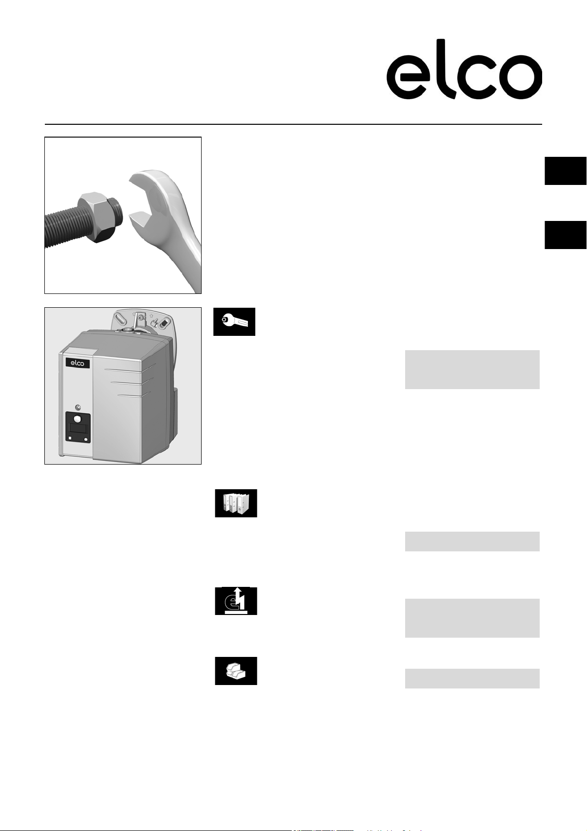
Branderbeschrijving
A1 Branderautomaat
A4 Display
B10 Ionisatiebrug
F6 Luchtpressostaat
GP Sluiterschijf voor propaangas
M1 Elektromotor
pL Luchtdruknippel
T1 Ontstekingstransformator
3 Gasblokaansluitflens
5 Bevestigingsschroeven voor
basisplaat
7 Inhangvoorziening (Service)
8 Behuizing
9 Elektrische aansluiting (bedekt)
14 Ontgrendelingsknop
15 Gaskopinstelschroef
16 Afdekkap
17 Branderaansluitflens
18 Branderbuis
103B Luchtregeling
113 Luchtkast
10/2016 - Art. Nr. 4200 1016 3901A 3
Page 4
Werking
VR4625
MB-DLE 407
met TC
MB-DLE 407
zonder TC
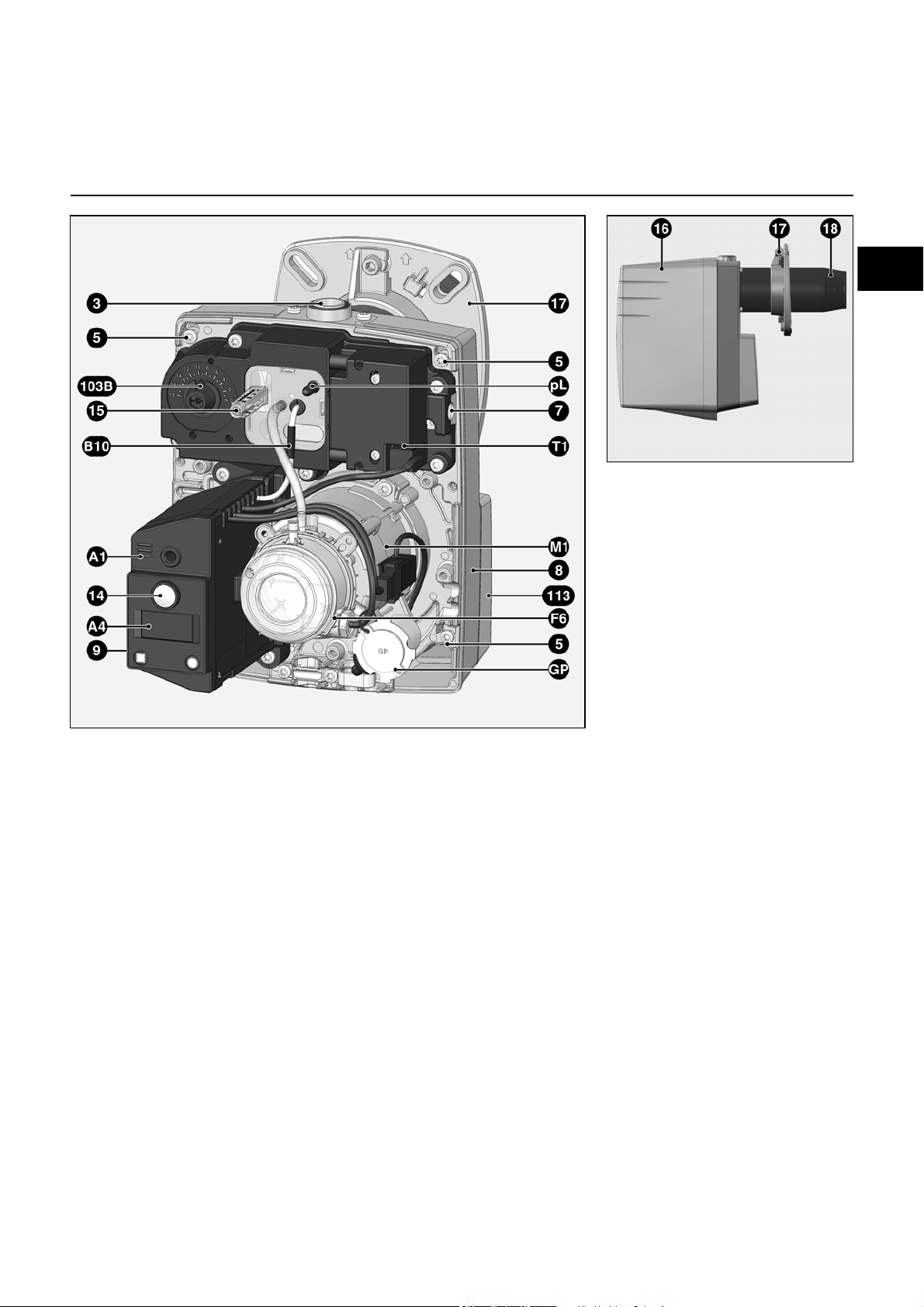
Gasblok VR4625 / MB-DLE 407
De compacte eenheid met geïntegreerde gasdrukregeling VR 4625 is
geschikt voor de werking van enkeltraps
aangeblazen gasbranders.
Het compacte gasblok is geregistreerd
onder nummer: CE-0063AP3090
Technische gegevens
Ingangsdruk 15-60mbar
Omgevingstemperatuur 0 tot +60° C
Spanning 230 V/50 Hz
Opgenomen vermogen 19W
Beschermingsgraad IP40
Gasaansluiting Rp 1/2"
Werkingsprincipe
Bij het aanleggen van de spanning aan
de magneetspoel opent ventiel Y12 en
ventiel Y13. De ventielzittingen worden
door een fijn zeef aan de inlaat
beschermd tegen vervuiling. De
ingebouwde drukregelaar regelt de
gewenste uitgangsdruk.
De vereiste instelwaarden voor:
- Gaspressostaat
- Gasdrukregelaar
- Startgasdruk (MB-DLE407)
kunnen via de bijstelschroeven worden
ingesteld. Ingangs- en uitgangsdruk
kunnen aan de meetnippels worden
gemeten.
F4 Pressostaat (instelschroef
onder de kap)
Y12 Veiligheidsventiel
Y13 Hoofdventiel
2 Elektrische aansluiting
ventielen
8 Inlaatflens
9 Elektrische aansluiting
pressostaat
104/C Instelschroef drukregelaar
106 Gaszeef
119 Meetnippel gasingang
119.1 Meetnippel gasdruk in de
tussenruimte van de ventielen
119pBr Meetnippel gasuitgang
10/2016 - Art. Nr. 4200 1016 3901A4
De compacte eenheid met geïntegreerde gasdrukregeling MB-DLE 407 is
geschikt voor de werking van enkeltraps
aangeblazen gasbranders.
Het compacte gasblok is geregistreerd
onder nummer: CE-0085AP3156
Technische Gegevens
Ingangsdruk 13-360mbar
Omgevingstemperatuur -15 tot +60° C
Spanning 230 V/50 Hz
Opgenomen vermogen 46W
Beschermingsgraad IP54
Gasaansluiting Rp 3/4"
Page 5
nl
Werking
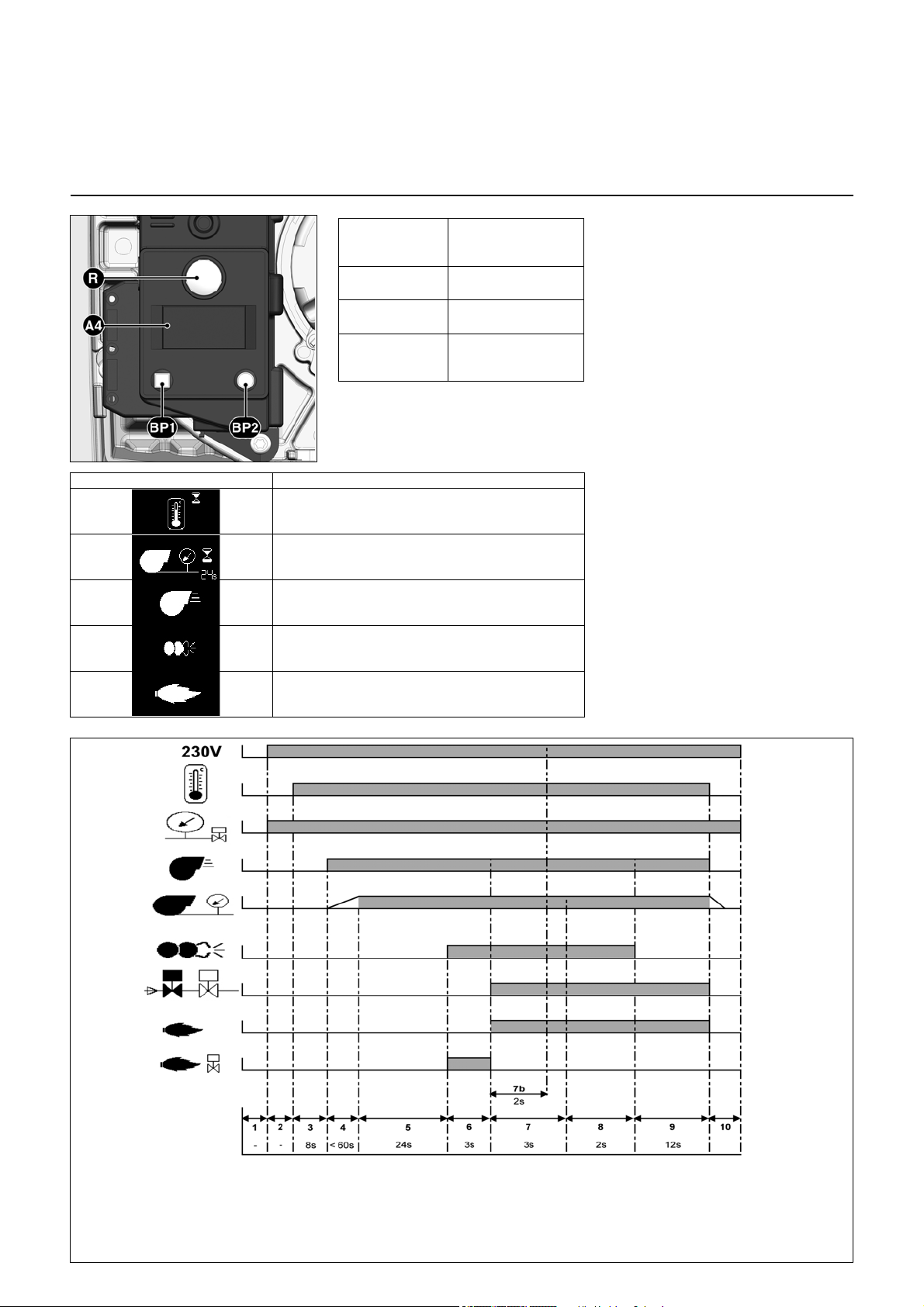
Fasen werkingsverloop:
1: Geen spanning
2: spanningsvoeding aanwezig, geen
warmteverzoek
3: Warmteverzoek, controle luchtpres-
sostaat ruststand
4: Motor ingeschakeld, controle luchtdruk
5: Eerste fase dichtheidstest
6: Testtijd 1 (tussenruimte ventielen
drukloos)
7: Tweede fase ventieltest
8: Testtijd 2 (tussenruimte ventielen gevuld)
9: Voorventilatie
9': Voorontsteking, activering parasietlicht-
bewaking
10: Vlamvorming, veiligheidstijd
11: Naontstekingstijd
12: Werking
13: Branderstilstand
15: Werkingsgereedheid
VG1/TC
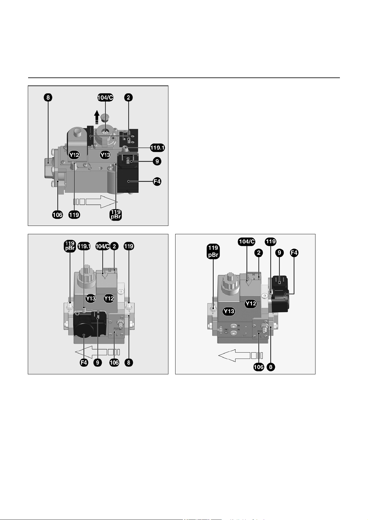
Branderautomaat TCG 1xx
met functie TC
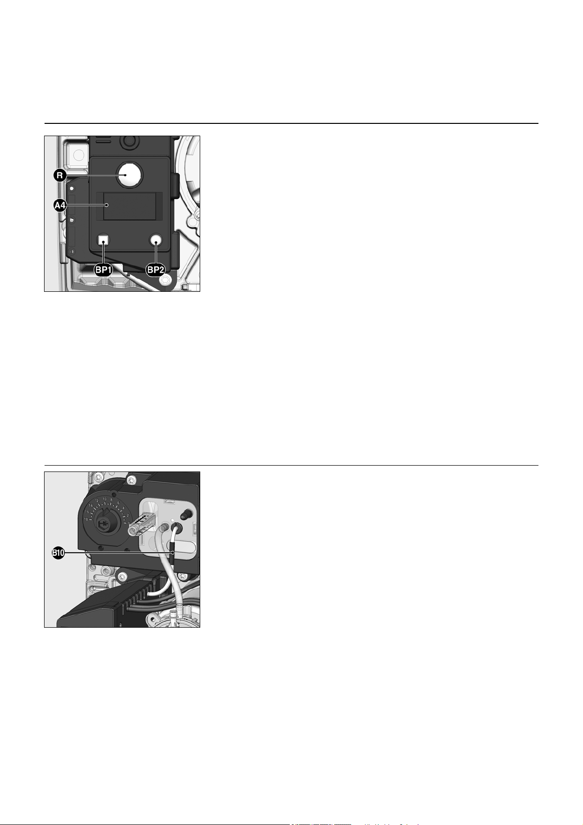
De knop R
indrukken tijdens
...
… 1 seconde ... Ontgrendelen van de
… 2 seconden... Vergrendelen van de
… 9 seconden... Wissen van de statis-
A4 Scherm
BP1 Drukknop 1
Opvraging: Storingscode
BP2 Drukknop 2
Opvraging: Waarden
Symbool Naam
Wacht op warmteverzoek
Ventieldichtheitstest
(door gasdrukmeting in de tussenruimte van de
ventielen)
Wacht op luchtpressostaat bij branderstart
Brandermotor ingeschakeld
… veroorzaakt ...
automaat
automaat
tieken van de
automaat
De gasbranderautomaat TCG 1xx stuurt
en bewaakt de aangeblazen brander.
Door het microprocessorgestuurde
programmaverloop worden uiterst
stabiele tijden bereikt, die onafhankelijk
zijn van schommelingen in netspanning
en omgevingstemperatuur. De
branderautomaat is berekend op
onderspanning, daardoor komt de
werking van de installatie ook bij hevige
spanningsdalingen niet in gevaar. Als de
netspanning onder de vereiste
minimumwaarde ligt, schakelt de
automaat uit zonder storingssignaal.
Nadat weer een normale spanning is
bereikt, start de automaat weer
automatisch.
Vergrendeling en ontgrendeling
De automaat kan via de ontstoringsknop
R worden vergrendeld (in
storingstoestand gebracht) en worden
ontgrendeld (uit storingstoestand
gehaald), op voorwaarde dat
netspanning voorhanden is aan de
automaat.
Voor het in- of uitbouwen van de
automaat moet het apparaat
spanningsvrij worden gemaakt. De
automaat mag niet geopend of
gerepareerd worden.
Ontstekingstranformator ingeschakeld
vlam aanwezig
10/2016 - Art. Nr. 4200 1016 3901A 5
Page 6
Werking
1: Geen spanning
2: Elektrische voeding aanwezig,
geen verzoek om verwarming
3: Verzoek om verwarming, controle
van de ruststand van de luchtdrukbewaker
4: Motor gevoed, controle van de
luchtdruk
5: Voorventilatie
5': Voorontsteking, activering van de
vreemd lichtbewaking
6: Vlamvorming, veiligheidstijd
7: Tijd van de naontsteking
8: Werking
9: Stoppen van de brander
10: Stoppen van de regeling
VG1
Branderautomaat TCG 1xx
zonder functie TC
De knop R
indrukken tijdens
...
… 1 seconde ... Ontgrendelen van de
… 2 seconden... Vergrendelen van de
… 9 seconden... Wissen van de statis-
A4 Scherm
BP1 Drukknop 1
Opvraging: Storingscode
BP2 Drukknop 2
Opvraging: Waarden
Symbool Naam
Wacht op warmteverzoek
Wacht op luchtpressostaat bij branderstart
Brandermotor ingeschakeld
Ontstekingstranformator ingeschakeld
… veroorzaakt ...
automaat
automaat
tieken van de
automaat
De gasbranderautomaat TCG 1xx stuurt
en bewaakt de aangeblazen brander.
Door het microprocessorgestuurde
programmaverloop worden uiterst
stabiele tijden bereikt, die onafhankelijk
zijn van schommelingen in netspanning
en omgevingstemperatuur. De
branderautomaat is berekend op
onderspanning, daardoor komt de
werking van de installatie ook bij hevige
spanningsdalingen niet in gevaar. Als de
netspanning onder de vereiste
minimumwaarde ligt, schakelt de
automaat uit zonder storingssignaal.
Nadat weer een normale spanning is
bereikt, start de automaat weer
automatisch.
Vergrendeling en ontgrendeling
De automaat kan via de ontstoringsknop
R worden vergrendeld (in
storingstoestand gebracht) en worden
ontgrendeld (uit storingstoestand
gehaald), op voorwaarde dat
netspanning voorhanden is aan de
automaat.
Voor het in- of uitbouwen van de
automaat moet het apparaat
spanningsvrij worden gemaakt. De
automaat mag niet geopend of
gerepareerd worden.
vlam aanwezig
10/2016 - Art. Nr. 4200 1016 3901A6
Page 7
nl
Werking
Stekker
nr.
Klem
Klem
Stekker
nr.
Vlamcontrole
Afstandsontgren
deling
Ontste-
Brandermotor
LuchtpressostaatGaspressostaat Stroomvoeding L1
Display Storing
Magneetventiel
Aarde
Aarde
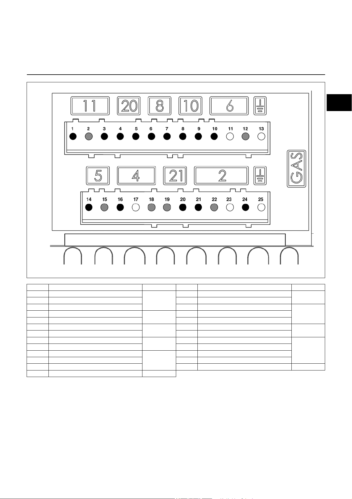
Aansluitschema
Aansluitsokkel
Klem Benaming Stekker nr. Klem Benaming Stekker nr.
1 Signaal vlamdoofveiligheid
2 Neutraal 15 Neutraal
3 Fase 16 Fase brandermotor
4 Signaal afstandsontgrendeling
5 Fase 18 Neutraal
6Fase
7 Signaal gaspressostaat 20 Fase display storing
8 Signaal luchtpressostaat
9 Fase 22 Neutraal
10 Fase
11 Aarde 24 Fase hoofdgasventiel
12 Neutraal 25 Aarde
13 Aarde
11
20
8
10
6
14 Fase onstekingstransformator
17 Aarde
19 Neutraal
21 Fase veiligheidsventiel
23 Aarde
5
4
21
1
10/2016 - Art. Nr. 4200 1016 3901A 7
Page 8
Werking
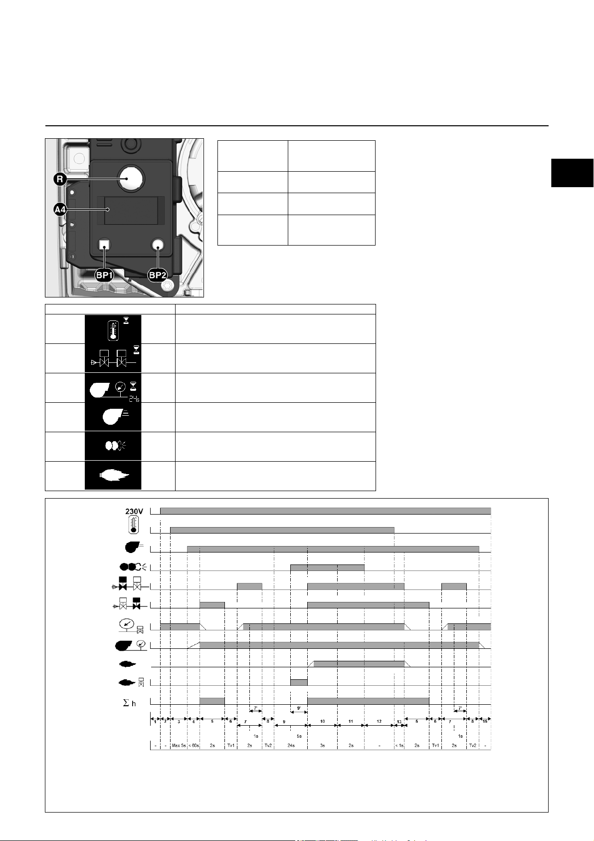
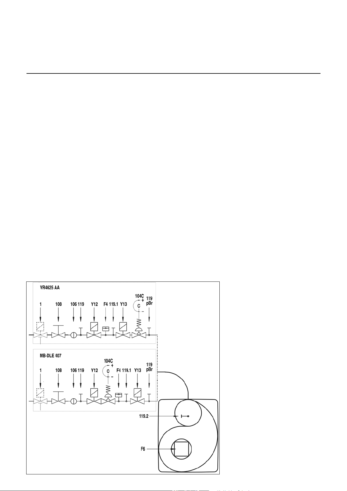
Compacte blok
Werkingsfunctie
Veiligheidsfunctie
Werkingsfunctie
(Branders met functie TC)
Bij het voor de eerste maal inschakelen,
na een stroomonderbreking of een
uitschakelen in storingstoestand, na
gasgebrek of na 24 uur stilstand wordt
vóór de start van de brander een lektest
van de gasventielen doorgevoerd terwijl
de ventilatormotor draait. Na de
afdichtingscontrole begint de
voorventilatietijd van 24 sec.
Werkingsfunctie
(Branders zonder functie TC)
Bij de eerste in bedrijfstelling, na
stroomuitval of het in werking komen
van de beveiliging, na een onderbreking
van de gastoevoer of na stilstand van 24
uur begint een voorventilatietijd van
24 sec.
Tijdens het voorspoelen wordt
- de ventilatordruk bewaakt
- de verbrandingskamer bewaakt op
vlamsignalen.
Na afloop van de voorspoeltijd
- wordt de ontsteking aangekoppeld
- wordt het hoofd- en
veiligheidsmagneetventiel geopend.
- Brander start
Bewaking
De vlam wordt bewaakt door een
ionisatiesonde. De sonde is geïsoleerd
op de gaskop gemonteerd en voert door
de stuwschijf naar de vlamzone. De
sensor mag niet in elektrisch contact
komen met geaarde onderdelen. Als er
tussen sonde en brandermassa
kortsluiting optreedt, schakelt de
brander op storing.
Bij branderwerking ontstaat in de
gasvlam een geïoniseerde zone,
waardoor een gelijkgerichte stroom van
de sonde naar de brandermond stroomt.
De ionisatiestroom moet ten minste 8 µA
bedragen.
Veiligheidsfuncties
- Als zich bij de start van de brander
(toelating gastoevoer) geen vlam
vormt, dan wordt na afloop van de
veiligheidstijd van max. 3 seconden
de brander uitgeschakeld en het
gasventiel wordt gesloten.
- Bij een verdwijning van de vlam
gedurende de werking wordt de
gastoevoer binnen een seconde
onderbroken. Er wordt dan een
nieuwe start uitgevoerd. Als de
brander start, wordt de werking
voortgezet. In tegengesteld geval
volgt een uitschakelen in
storingstoestand.
- Bij gebrek aan lucht gedurende de
voorventilatie of de werking volgt
uitschakelen in storingstoestand.
- Bij gasgebrek gaat de brander niet in
werking of wordt uitgeschakeld. Er
volgt een wachttijd van 2 minuten.
Daarna wordt nog een startpoging
uitgevoerd. Als daarna geen gasdruk
voorhanden is, volgt nog een wachttijd
van 2 minuten. De wachttijd kan alleen
door een spanningsonderbreking van
de brander worden gereset.
Wachttijden: 3 x 2 min, daarna 1 uur
Bij uitschakelen van de regeling
- De regelthermostaat onderbreekt het
warmteverzoek
- De gasmagneetventielen gaan dicht
- De vlam dooft
- Ventilatormotor blijft in werking
gedurende beperkte tijd (14 sec)
- De lekkagetest van de ventielen wordt
uitgevoerd
- De brandermotor wordt uitgeschakeld
- De brander is klaar voor werking
(Branders met functie TC)
F4 Gasgebrekbeveiliging
F6 Luchtgebrekbeveiliging
Y13 Hoofdmagneetventiel
Y12 Veiligheidsmagneetventiel
1 Thermisch gestuurde
veiligheidsafsluiter
(ter plekke aan te brengen)
104 Gasdrukregelaar
106 Zeef
108 Gaskogelkraan (ter plekke aan
te brengen)
119pBr Meetpunt gasuitlaatdruk
119.1 Meetpunt gasdruk in
tussenruimte ventielen
119.2 Meetpunt luchtdruk
Aanwijzing CH
In de gastoevoerleiding moet volgens de
SVGW-gasrichtlijnen een
veiligheidshoofdgasventiel worden
geplaatst (nummer 1).
Aanwijzing DE
Gasverbrandingsruimten moeten
volgens monsterverbrandingsverordening met een
thermisch gestuurd afsluitventiel
(nummer 1) uitgerust zijn.
10/2016 - Art. Nr. 4200 1016 3901A8
Page 9
nl
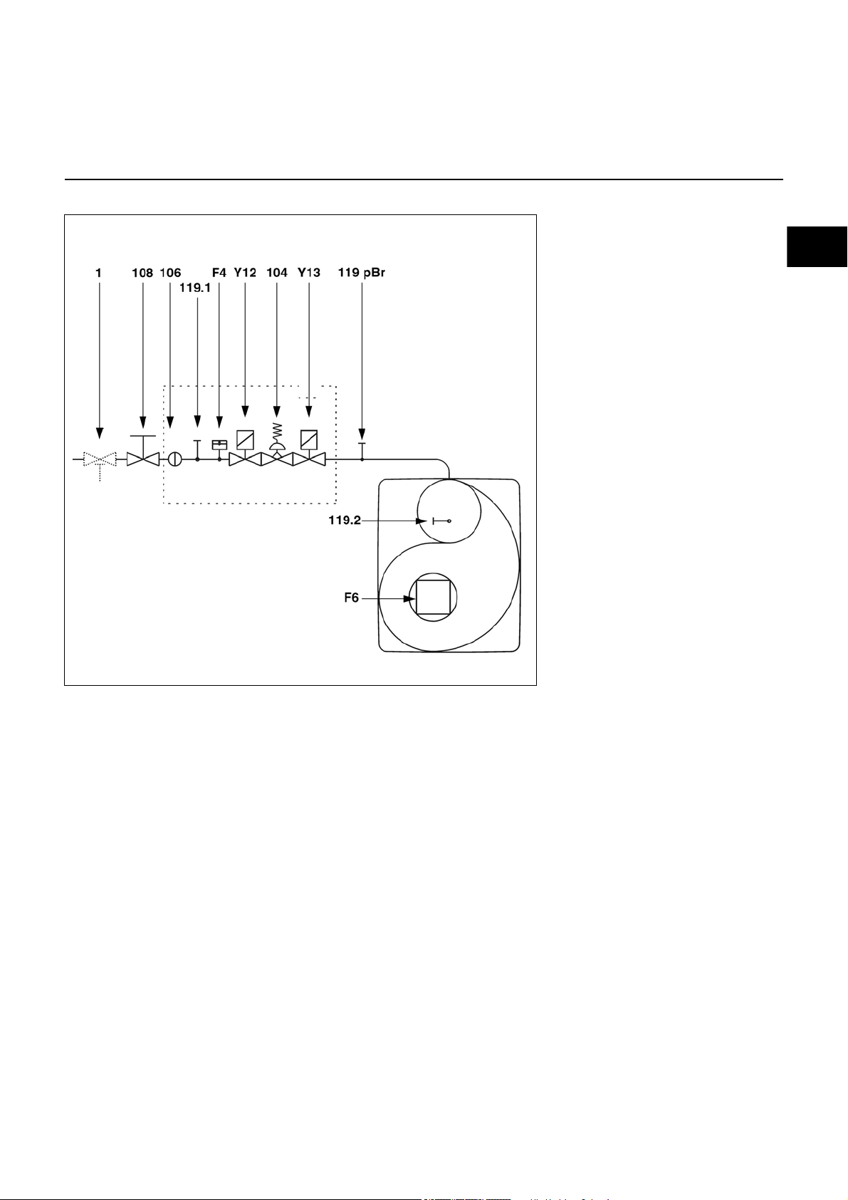
Compact gasblok
Werking
Werkingsfunctie
Veiligheidsfunctie
(Branders zonder functie TC)
F4 Gasgebrekbeveiliging
F6 Luchtgebrekbeveiliging
Y13 Hoofdmagneetventiel
Y12 Veiligheidsmagneetventiel
1 Thermisch gestuurde
veiligheidsafsluiter
(ter plekke aan te brengen)
104 Gasdrukregelaar
106 Zeef
108 Gaskogelkraan (ter plekke aan
te brengen)
119pBr Meetpunt gasuitlaatdruk
119.1 Meetpunt gasdruk in
tussenruimte ventielen
119.2 Meetpunt luchtdruk
10/2016 - Art. Nr. 4200 1016 3901A 9
Page 10
Montage
Brandermontage
Branderinbouwstand
Gasaansluiting, Inbouwwijze
Montage van de brander
De branderflens 3 is voorzien van
langwerpige gaten en kan worden
gebruikt voor een diameter van de
gatencirkel gaande van 150 tot 170 mm.
De afmetingen voldoen aan EN 226. De
flensdichting voor de brander en de
bevestigingsschroeven worden samen
met de brander geleverd.
Door verschuiven van buizensteun 2 op
de branderbuis kan de insteekdiepte van
de menginrichting worden aangepast
aan de afmetingen van de
verbrandingsruimte. De insteekdiepte
blijft ongewijzigd bij het in- en uitbouwen.
Via de buishouder 2 wordt de brander
aan de aansluitflens en dus aan de ketel
Gasverzorging
De diameter van de gasleidingen moet
dusdanig worden gekozen, dat de
drukverliezen niet meer dan 5% van de
netdruk bedragen.
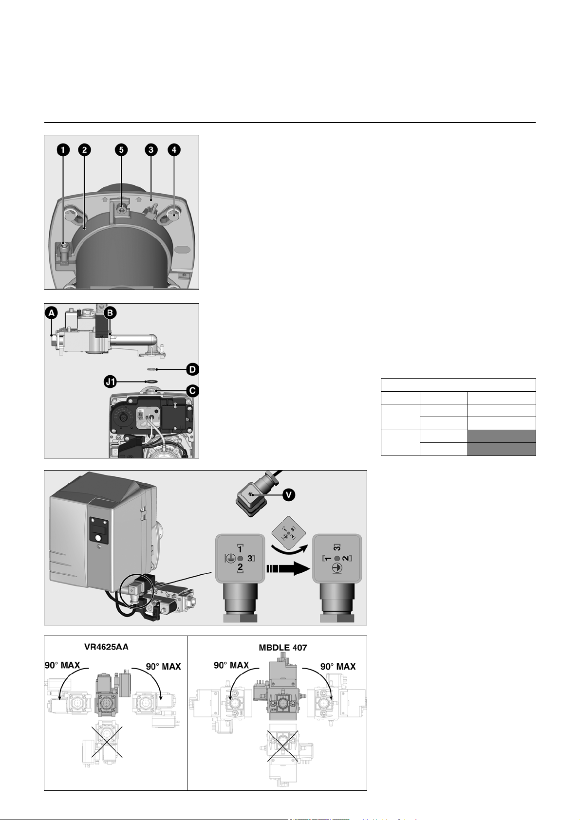
Montage van het gasblok
• De doppen op A, B en C verwijderen.
• Controleren of ringafdichting J1
aanwezig is en correct op de flens C
ligt.
• Gasblok rechts of links bevestigen (zie
hieronder voor andere
inbouwstanden).
Montage gasdiafragma D (VG1.40)
(zie tabel aan de rechterkant)
• Gaskogelkraan voor het gasblok
installeren.
bevestigd. De verbrandingsruimte wordt
hierdoor dicht afgesloten.
Inbouwen:
• Aansluitflens 3 met schroeven 4 aan
de ketel bevestigen.
• Buizensteun 2 op branderbuis
monteren en met schroef 1
bevestigen. Schroef 1 met een
aanspanmoment van max. 6 Nm
vastdraaien.
• Brander enigszins draaien, in de flens
invoeren en met schroef 5 bevestigen.
Uitbouwen:
• Schroef 5 losdraaien.
• Brander uitdraaien en uit de flens
trekken.
Aanwijzing
Er moet voldoende plaats worden
voorzien om bij de verschillende
instelpunten te kunnen komen. De
gasverzorgingsleiding moet grondig
worden ontlucht. Alle verbindingen
moeten worden gecontroleerd op
dichtheid.
Gebruik diafragma D
Brander Gassoort Diafragma
VG 1.40 Aardgas zilver Ø 6,7 mm
Propaangas zwart Ø 4,5 mm
VG 1.55/
85/105
Aardgas
Propaangas
Voor een montage in omgekeerde
positie moet de connector van de gasdrukregelaar anders gemonteerd zijn.
Verwijder daartoe de V-schroef, haal
het binnengedeelte van de connector
gedeeltelijk uit, laat het een kwartslag
tegen de klok in draaien en monteer
alles terug.
Voor een montage in omgekeerde
positie moet de weergave omgekeerd
worden. Ga daartoe als volgt te werk
terwijl de brander in bedrijf is:
De knoppen BP1 en BP2 tegelijkertijd
ingedrukt houden tot u de verandering
opmerkt.
Toegestane inbouwstanden van de
gasventielen
10/2016 - Art. Nr. 4200 1016 3901A10
Page 11
nl
Montage
VR4625
MB-DLE 407
Werking met propaan
Elektrische aansluiting
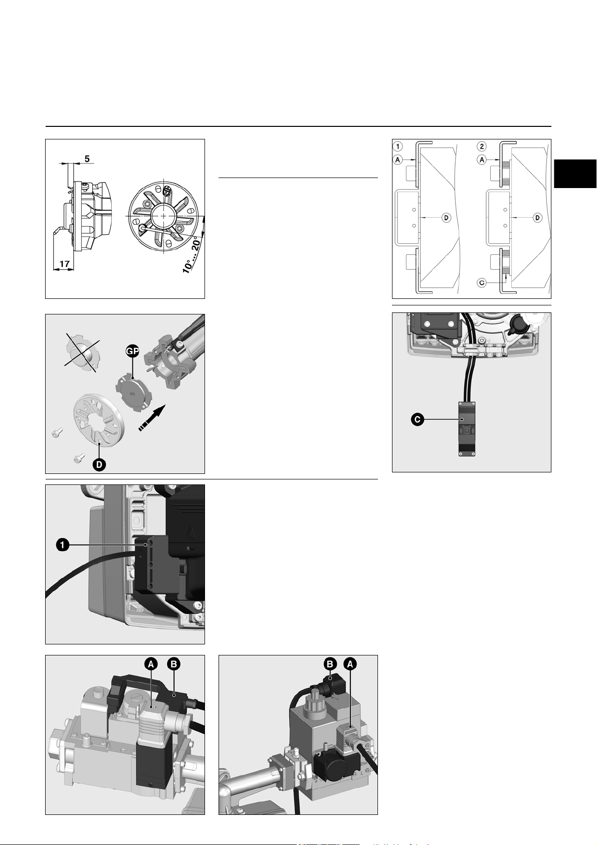
Instelling van de ionisatiesonde en de
onstekingselektrode
Zie afbeelding
Tekening 1 :
Standaardinstelling
Tekening 2 :
Instelling van de branderkop voor
oudere
verwarmingsketels met tendens tot
CO-uitstoot
• De twee schijven C tussen de stuw-
schijf A en het aardgasdiafragma D
monteren.
Werking met propaan
Voor werking met propaan moet het
aardgasdiafragma worden vervangen
door het propaandiafragma dat op de
basisplaat is bevestigd.
Hiervoor:
• Gaskop demonteren (zie onderhoud).
• Stuwschijf D losdraaien en het
aardgasdiafragma verwijderen.
• Propaangasdiafragma GP met
gravering naar boven installeren en
de stuwschijf vastschroeven.
• Gaskop weer monteren.
Elektrische aansluiting tussen brander
en ketel
De elektrische installatie en de werkzaamheden voor de aansluiting mogen alleen
door een erkend gespecialiseerd elektrotechnicus worden uitgevoerd. Daarbij
dienen de geldende voorschriften en bepalingen in acht te worden genomen.
Deze brander omvat elektronische componenten; we raden aan vóór de installatie
een automatische differentieelschakelaar
van het type A te voorzien om zwerfstromen met een gelijkstroomcomponent op te
sporen.
• Controleren of de netspanning met de
opgegeven bedrijfsspanning van 230 V 50 Hz overeenstemt.
• Veiligheidszekering van de brander:
10 A.
10/2016 - Art. Nr. 4200 1016 3901A 11
De elektrische potentiaal van de nulleiding moet identiek zijn aan die van de
aardleiding. Als dat niet zo is, moet de
elektrische voeding van de brander gerealiseerd worden met een scheidingstransformator gevolgd door de aangewezen
beveiligingen (zekering en differentieelschakelaar 30 mA).
Brander en generator (ketel) worden met
elkaar verbonden via een 7-polige stekkerverbinding 1.
Voor een correcte werking van de
brander dient u de polariteit van de
geleiders bij de aansluiting van de
7P-stekker te respecteren.
De brander moet van het net gescheiden
kunnen worden met behulp van een meerpolige scheidingsinrichting die conform de
geldende normen is.
Elektrische aansluiting
veiligheidsgasventiel (CH)
•
Het veiligheidshoofdgasventiel (ter
plekke aan te brengen) wordt op de
stekker
Elektrische aansluiting compacte
brandereenheid
• De verbinding met de compacte
gaseenheid wordt gerealiseerd via
twee stekkers die aan de klemmenrij
van de brander voorbekabeld zijn.
• Stekker
overeenkomstige apparaatstekkers
van de compacte gaseenheid
aansluiten en met de schroeven
borgen.
Stekker
Stekker
C
aangesloten.
A
en B aan de
A
: Gaspressostaat
B
: Gasventiel
Page 12
Inwerkingstelling
Testen voor de inwerkingstelling
Ionisatiestroommeting
Testen voor de inwerkingstelling
Voor de inwerkingstelling van de
brander moeten volgende testen en
controles worden uitgevoerd.
- Werkingsvoorschriften van de
fabrikant van de warmteproducerende
uitrusting
- Instelling van
- Temperatuurregelaar
- Drukregelaar
- Begrenzer
- Veiligheidsschakelaar
- Gasaansluitingsdruk min. 20mbar
stroomdruk.
- Dichtheid van de
gasleidingselementen
- Ontluchting van brandstofleidingen
- Open rookgasleidingen, voldoende
toevoer van verse lucht.
Controle programmaverloop van de
brander zonder vlamvorming
De branderautomaat activeert bij het
eerste inschakelen de
dichtheidscontrole. Daartoe moet
gasdruk voorhanden zijn. Om eerst het
volledige programmaverloop zonder
vlamvorming te controleren, na
voltooiing van de dichtheidscontrole het
manuele gasventiel weer sluiten.
Als volgt te werk gaan:
• Manuele afsluiter openen
• De brander starten door de
warmteproducerende uitrusting te
starten
• De uitvoering van de
dichtheidscontrole vervolgens via de
display voortzetten
• Na het openen van het tweede ventiel,
de manuele afsluiter weer sluiten.
• Het programma doorloopt het
uitschakelen in storingstoestand (de
storingslamp brandt) na het einde van
de veiligheidstijd of gasgebrek treedt
op
• Brander spanningsloos schakelen
• De manuele afsluiter weer openen, de
brander weer met spanning voeden,
eventueel ontgrendelen en opnieuw
starten.
Ionisatiestroommeting
De ionisatiestroom kan op de hiertoe
voorziene meetpunten worden
gemeten. Hiertoe de meetbrug B10
verwijderen en een multimeter met een
meetbereik van 0-100µA aansluiten.
De bewakingsstroom moet ten minste
8 µA bedragen.
10/2016 - Art. Nr. 4200 1016 3901A12
Page 13

nl
Inwerkingstelling
Gasty p e
Gasdruk
in de k o p
119 pBr
(daPa)
Luchtdoseer-
trom m el
103 B
0 tot 18
Luchtdruk
in de k o p
pL
(daPa)
Maat
Y
(mm)
Inste llin g
Gaspresso-
staat
(daPa)
ge le id in g
Positie
15 22 4 13 10 1
25 36 7 14 20 1
35 69 10 19 25 1
40 36 11 26 25 1
50 44 15 27 30 1
62 76 10 46 25 -
76 104 12 45 30 -
86 126 18 55 35 45 52 3 65 10 -
75 110 12 70 23 -
100 165 18 75 35 -
15 34 3 5 22 1
25 84 7 12 25 1
35 156 11 20 30 1
40 50 12 28 25 1
50 63 18 29 30 1
59 76 10 45 25 70 93 13 45 30 85 123 18 56 35 45 55 2 57 14 75 110 12 65 25 -
100 150 18 75 35 -
(1): F ab rie ksinste llin g
G20
G25
100 (1)
G31
VG1.40
100
VG1.55
VG1.85
V
Brander-
verm ogen
(kW )
V
VG1.40
VG1.55
VG1.85
Instelgegevens
Luchtregeling
G1.105
Aanzuiglucht-
G1.105
Bovenstaande instelgegevens zijn basisinstellingen. De fabrieksinstelgegevens zijn vet omrand. Met deze instellingen kan
normaal gesproken de brander in bedrijf worden genomen. In ieder geval de instelwaarden zorgvuldig controleren. Correcties
vanwege de installatie kunnen noodzakelijk zijn.
De luchtregeling wordt gerealiseerd op
twee plekken:
- Aan de drukzijde van de ventilator
door middel van een
luchtdoseertrommel
- In de branderkop door middel van de
stuwschijf en het mondstuk van de
branderbuis.
De luchtdoseertrommel heeft een
lineaire regelkarakteristiek en wordt
bediend door verdraaien van de
regelknop 103B. De ingestelde waarde
kan via de instelschaal worden
gecontroleerd.
De luchtregeling in de branderkop
beïnvloedt behalve de luchthoeveelheid
ook de mengzone en de luchtdruk in de
branderbuis. Verdraaien van schroef 15
- naar rechts = minder lucht
- naar links = meer lucht
Op de schaalverdeling Y kan de stand
van de stuwschijf worden gecontroleerd.
De aanzuigluchtgeleiding 6 wordt in de
fabriek op 1 ingesteld.
Stand 1 = max. ventilatordruk
Stand 5 = min. ventilatordruk
In gevallen waar een hoge ventilatordruk
een nadeel is, bijvoorbeeld bij sterke
onderdruk in de haard, kan de druk
worden verminderd door de geleiding
van aanzuiglucht te veranderen:
• De bevestigingsschroef 7 losdraaien
• De geleiding van aanzuiglucht op een
nieuwe waarde instellen
• Schroef weer aanspannen.
10/2016 - Art. Nr. 4200 1016 3901A 13
Page 14

Inwerkingstelling
1
2
Instelling
Compacte gaseenheid VR4625
Instelling compacte gaseenheid
Op de meetpunten 119 en 119pBr
De sluiterschroeven losdraaien en
drukmeetapparaten aansluiten.
Instelling drukregelaar
De drukregelaar (schroef C) is in de
fabriek ingesteld en verzegeld.
Als de gasdruk ontregeld of te laag is,
als volgt te werk gaan om het gewenste
vermogen te bereiken:
Aan de brander:
• De branderkop en de luchtklep
volgens de tabel instellen.
Aan het ventiel:
• De beschermkap aan de drukregelaar
demonteren (104/C).
• Schroef C verdraaien:
- rechtsom: hoger vermogen
- linksom: minder vermogen
(Opgelet! Geen aanslag! Het volledige
instelbereik omhelst 10 slagen. Een
slag = 60 daPa).
• Druk pBr via schroef C instellen.
• Gasdruk op het punt 119 en 119pBr
meten.
Voorbeeld:
Voor een vermogen van 25kW met een
G1.40 zijn volgende instellingen van
kracht:
- Instelling branderkop: 20mm
- Luchtklepstand: 7
- Instelling van de gasdruk op
pBr= 42 daPa met schroef C.
Controle van de regelbaarheid
• De brander op de nominale belasting
laten werken.
• Gasdruk op punt 119 en punt 119pBr
meten.
• De kogelkraan voor de compacte
eenheid langzaam sluiten, tot de
ingangsdruk van het gas bij 119 met
20daPa daalt.
De gasuitgangsdruk bij 119pBr mag
daarbij ten hoogste over 10% dalen.
Anders moet de instelling worden
gecontroleerd en gecorrigeerd.
De installatie mag niet in bedrijf
worden genomen als de
regelbaarheid onvoldoende is.
• Kogelkraan weer openen.
• De beschermkap op de drukregelaar
monteren.
Elektrische aansluiting
Opgelet, als de grijze stekker op de
gaspressostaat niet correct
gemonteerd is (zie afbeelding 2), dan
gaat de brander over naar de
veiligheidsmodus en de foutmelding
„Wachten op gasdruk“ verschijnt.
10/2016 - Art. Nr. 4200 1016 3901A14
Page 15

nl
Inwerkingstelling
Borg-schroef Verzegelde
schroef
Instelling
Compacte gaseenheid MB-DLE407
Instelling drukregelaar
Voor het instellen van de uitgangsdruk
zijn 60 slagen van de instelschroef
mogelijk. Drie slagen rechtsom
verhogen de druk met 1 mbar, drie
slagen linksom verlagen de druk met
dezelfde waarde.
Bij de inwerkingstelling:
• Ten minste 20 slagen rechtsom (+)
• Gasdruk na de regelaar pBr moet zijn:
12-15 mbar (kan aan de meetnippel
van de gasdrukschakelaar worden
gemeten) 119.1).
Instelling nominale belasting
• De borgschroef losmaken tot de
draaiknop 6 kan worden versteld. De
verzegelde bout aan de
tegenoverliggende zijde niet losdraaien.
• De hoofddoorstroomhoeveelheid door
draaien aan knop 6 naar rechts
verminderen resp. door draaien naar
links verhogen. Het totale traject voor
verandering van minimaal tot maximaal
debiet is ongeveer 4,5 slagen.
• Wanneer de instelling met succes
voltooid is, de borgschroef weer
vastschroeven.
• Gasdruk op het meetpunt
(fabrieksinstelling op pagina 13).
119pBr
meten
Instelling startlasthoeveelheid snelslaginstelling
• Beschermkap 5 eraf draaien en over
180° gedraaid als regelgereedschap
gebruiken.
• Instelstift tot aan de aanslag naar min.stand draaien, dan in plus-stand tot
aan de middelste stand (ca. 3 halve
slagen) terugdraaien. De
startgashoeveelheid is nu ongeveer
half open.
• Om zacht opstartgedrag te bereiken
moet het gasdebiet bij het starten
worden aangepast aan de
drukverhoudingen van de
warmteproducerende uitrusting.
Verbrandingswaarden optimaliseren
Zo nodig verbrandingswaarden via
instelling van de stuwschijfstand (maat Y)
optimaliseren. Hierdoor kan het
startgedrag, de pulsatie en de
verbrandingswarmte worden beïnvloed. Bij
reductie van de schaalwaarde Y stijgt de
CO2-waarde, het startgedrag wordt echter
harder. Indien nodig
luchthoeveelheidwijziging door aanpassing
van luchtklepstand compenseren.
Let op: Minimaal noodzakelijke
rookgastemperatuur in acht nemen
volgens opgave van de ketelfabrikant
en overeenkomstig eisen
rookgaswegen ter voorkoming van
condensatie.
Controle van de regelbaarheid
• De brander op de nominale belasting
laten werken.
• Gasdruk op punt 119 en punt 119pBr
meten.
• De kogelkraan voor de compacte
eenheid langzaam sluiten, tot de
ingangsdruk van het gas bij 119 met
20daPa vermindert.
De gasuitgangsdruk bij 119pBr mag
daarbij ten hoogste met 10% dalen.
Overigens moet de instelling worden
gecontroleerd en gecorrigeerd.
De installatie mag niet in bedrijf
worden genomen als de
regelbaarheid onvoldoende is.
• Kogelkraan weer openen.
10/2016 - Art. Nr. 4200 1016 3901A 15
Page 16

Inwerkingstelling
Instelling luchtpressostaat
Instelling gaspressostaat
Werkingscontrole
Instelling gaspressostaat
• Voor instelling van de uitschakeldruk:
Het deksel van de gaspressostaat
verwijderen.
• Meetinrichting voor gasdruk pBr
aansluiten.
• Brander starten.
• Gasdruk voor blok verminderen door
het vernauwen van de kogelkraan, tot
ofwel:
- gasdruk pBr na het blok vermindert
tot 70%
- de stabiliteit van de vlam zichtbaar
afneemt
- de CO-waarde stijgt
- of het vlamsignaal verslechtert
merkbaar
Instelling luchtpressostaat
Voorinstelling van de fabriek: 1,0mbar
Het schakelpunt moet bij het inregelen
worden getest en bijgeregeld.
• Het drukmeetapparaat installeren,
daartoe T-stuk in de drukleiding
bouwen.
• Brander in werking stellen.
• Schakelpunt ongeveer 15% onder de
nu aanwezige uitschakeldruk
instellen.
• De instelschijf rechtsom draaien, tot de
gaspressostaat de brander
uitschakelt.
• Door verder rechtsom draaien de
gaspressostaat 10% hoger dan de
gemeten uitschakelwaarde instellen.
De instelwaarde van de
gasdrukschakelaar moet hoger liggen
dan de ventilatordruk, maar lager dan de
gasdruk na het gasventiel.
Controle van het uitschakelpunt:
• Manuele afsluiter openen
• Brander starten
• Manuele afsluiter sluiten
Het gasgebrekprogramma moet starten,
zonder dat de branderautomaat een
uitschakelen in storingstoestand
veroorzaakt.
Werkingscontrole
Een controle van de vlambewaking moet
zowel bij het eerste gebruik als ook na
een revisie of een lange stilstand van de
installatie worden uitgevoerd.
- Opstarttest met gesloten gasventiel:
Op het einde van de veiligheidstijd
moet de branderautomaat overgaan
op gasgebrek of storing.
- Opstarten met gesloten
luchtpressostaat:
De brander gaat na een controletijd
van 8 sec. over op storing.
- Opstartpoging met geopende
luchtpressostaat:
Na een wachttijd van 60 sec. gaat de
branderautomaat over op storing.
- Opstartpoging met korte, geopende
luchtpressostaaat gedurende de
voorventilatie:
De branderautomaat start het
voorventilatieprogramma opnieuw,
wanneer de luchtdruk binnen 60 sec.
opnieuw voorhanden is, anders volgt
een uitschakelen in storingstoestand.
10/2016 - Art. Nr. 4200 1016 3901A16
Page 17

nl
Service
Onderhoud
Servicewerkzaamheden aan de ketel
en brander mogen alleen door
geschoolde verwarmingsvakmensen
worden uitgevoerd. Om een
regelmatige uitvoering van het
onderhoud te waarborgen, moet aan
de gebruiker van de installatie het
afsluiten van een
onderhoudscontract worden
aanbevolen.
Opgelet
• Voor onderhouds- en
reinigingswerkzaamheden, de stroom
uitschakelen en de gasafsluiter
sluiten.
Controle van de rookgastemperatuur
• regelmatig de rookgastemperatuur
controleren.
• Ketel reinigen, als de
rookgastemperatuur de waarde van
de inbedrijfstelling met meer dan 30°C
overschrijdt.
• om de controle te vereenvoudigen een
rookgasthermometer aanbrengen.
Onderhoudspunten brander
Na het losdraaien van schroeven 5 kan
de basisplaat in de onderhoudsposities
worden gehangen.
Demontage gaskop
• Contramoer C van de gasbuishouder
losdraaien, dopmoer E inschroeven
• Gasbuis naar rechts onderaan
uittrekken
• Ontstekings- en ionisatiekabels
losmaken.
• Bij het opnieuw monteren, letten op de
correcte plaats van de kabels en de
goede zitting van de O-ringen J1 en
J2.
Onderhoudswerkzaamheden op de
brander
• De gasleidingscomponenten (slangen,
leidingen) alsook hun verbindingen
controleren op lekkages en tekenen
van slijtage. Eventueel vervangen.
• De elektrische aansluitingen en
verbindingskabels controleren op
beschadigingen. Eventueel
vervangen.
• Gasfilter controleren, eventueel
reinigen of vervangen.
• Turbine en behuizing reinigen en
controleren op beschadigingen.
• Menginrichting controleren en
reinigen.
• Ontstekingselektrodenblok
controleren, eventueel bijstellen of
vervangen.
• Brander starten, rookgasgegevens
Montage van de turbine
Bij vervanging van de motor en de
turbine, het volgende
positioneringsschema in acht nemen.
De binnenste flens A van de turbine
moet ter hoogte van de basisplaat B
worden aangebracht. Een lineaal tussen
de schoepen van de turbine voeren en A
en B op dezelfde hoogte brengen,
tapeind aan de turbine aantrekken
(onderhoudspositie 2).
10/2016 - Art. Nr. 4200 1016 3901A 17
controleren, eventueel
branderinstellingen corrigeren.
• Instelling van lucht- en gaspressostaat
controleren.
• Regelbaarheid van het gasblok
controleren.
• Werkingscontrole uitvoeren.
Resetten van de onderhoudsindicator
Het onderhoudssymbool verschijnt op
het display van de automaat na 30 000
keer starten. Daarom is het noodzakelijk
om na elk onderhoud de onderhoudsteller te resetten. Druk hiertoe langer dan 9
seconden op de ontgrendelingsknop
van de automaat.
Page 18

Service
Storingen verhelpen
Oorzaken en verhelpen van
storingen
Als de storing blijft bestaan, de volgende
tabel gebruiken.
Gebruik alleen originele
onderdelen van de fabrikant.
Bij storingen moeten de principiële
voorwaarden voor een goede werking
worden gecontroleerd:
1. Is er stroom aanwezig?
2. Is er gasdruk aanwezig?
3. Is de gasafsluiter geopend?
4. Is alle regel- en
veiligheidsapparatuur, zoals
ketelthermostaat, beveiliging
watertekort, eindschakelaars enz.
De componenten die met veiligheid
verband houden, mogen niet worden
gerepareerd, en moeten door onderdelen
met hetzelfde bestelnummer worden
vervangen.
Aanwijzing:
Na iedere ingreep:
• Onder de werkelijke
werkingsvoorwaarden (deuren
gesloten, kap gemonteerd enz.) de
verbranding controleren en alle
leidingen op dichtheid controleren.
• De resultaten in de betreffende
documenten noteren.
correct ingesteld?
Symbool Storing Oorzaak Verhelpen
geen aanvraag naar warmte Thermostaat defect of ontregeld. Thermostaten instellen of vervangen.
Brander start niet na
thermostaatuitschakeling.
Er is geen storingsmelding op de
branderautomaat.
De brander start bij het
inschakelen heel kort, schakelt uit
en de rode lichtdiode gaat
branden.
De brander start niet. Luchtpressostaat: niet in rusttoestand
De brander start niet.
Gasdruk normaal
De branderventilator start. De
brander start niet.
Geen of te lage netspanning.
Storing van de automaat
De automaat werd opzettelijk uitgeschakeld. Automaat ontgrendelen.
Foutieve instelling
Contact gelast
onvoldoende gasdruk
Gaspressostaat ontregeld of defect
Luchtpressostaat: het contact sluit niet. Druksensor controleren (vreemde
Oorzaak van te lage spanning of van
stroomonderbreking opsporen.
De automaat vervangen.
Pressostaat opnieuw instellen.
Pressostaat vervangen.
Gasleidingen controleren.
Filter reinigen.
Gaspressostaat controleren of
compacte gaseenheid vervangen.
voorwerpen) en bekabeling controleren.
De branderventilator start. De
brander start niet.
Brander start, ontsteking schakelt
in, dan afbreking
De brander stopt terwijl hij werkt. Luchtpressostaat: Contact opent bij de start of
Strooilicht bij de voorventilatie of
voorontsteking.
Geen vlam na afloop van de beveiligingstijd.
Het gasdebiet is foutief ingesteld.
Storing in het vlambewakingscircuit
Geen ontstekingsboog.
Elektrode(n) kortgesloten.
Ontstekingskabel beschadigd of defect.
Ontstekingstransformator defect.
Branderautomaat.
De magneetventielen openen niet.
Klemmen van de ventielen.
tijdens werking.
De vlam verdwijnt gedurende de werking.
Ventiel controleren. Vlambewaking
controleren.
Gasdebiet regelen.
Toestand en stand van de
ionisatiesonde t.o.v. de massa
controleren.
Toestand en aansluitingen van het
ionisatiecircuit controleren (kabel en
meetbrug).
Elektrode(n) instellen, reinigen of
vervangen.
De kabel(s) aansluiten of vervangen.
Trafo vervangen.
De automaat vervangen.
Kabels tussen automaat en externe
componenten controleren.
Compacte gaseenheid vervangen.
Ventielen vervangen.
Pressostaat instellen of vervangen.
Circuit van de ionisatiesonde
controleren.
Branderautomaat controleren of
vervangen.
10/2016 - Art. Nr. 4200 1016 3901A18
Page 19

nl
Service
Aanduiding onderhoudsinterval
Gedurende de werking kunnen na enige
tijd de volgende inlichtingen verschijnen:
A4 Scherm
BP1 Drukknop 1
Opvraging: Storingscode
BP2 Drukknop 2
Opvraging: Waarden
Om het telefoonnummer te wijzigen:
• Door indrukken van BP1 het
storingsmenu oproepen en de uitlezing
door verder bedienen van BP1 laten
doorlopen tot het gewenste pictogram
verschijnt.
• Op BP2 drukken om de wijziging in te
geven: het eerste cijfer knippert.
• De waarde (van 0 tot 9) door herhaald
drukken van BP1 kiezen.
• Op BP2 drukken om te bevestigen.
• De procedure herhalen tot het laatste
cijfer.
Dat betekent dat het
tijd is voor
door een vakman.
Als de installateur zijn
telefoonnummer
heeft opgetekend, dan
verschijnt dat,
alsook het
nummer van het
afgesloten
onderhoudscontract
(toegankelijk via het
storingsmenu)
onderhoud
Na het bevestigen van het laatste cijfer,
wordt het volledige pictogram gedurende
5 sec. weergegeven. Daarna verschijnt
opnieuw de werkingsuitlezing.
Om het contractnummer te wijzigen:
• Door indrukken van BP1 het
storingsmenu oproepen en de uitlezing
door verder bedienen van BP1 laten
doorlopen tot het gewenste pictogram
"Contractnummer" verschijnt.
• Op BP2 drukken om de wijziging in te
geven: het eerste cijfer knippert.
• De waarde (van 0 tot 9) kiezen door
herhaald drukken van BP1.
• Op BP2 drukken om te bevestigen.
• De procedure herhalen tot het laatste
cijfer.
Na het bevestigen van het laatste cijfer,
wordt het volledige pictogram gedurende
5 sec. weergegeven. Daarna verschijnt
opnieuw de werkingsuitlezing.
10/2016 - Art. Nr. 4200 1016 3901A 19
Page 20

Overview
Contents
Overview Contents.................................................................. 20
Important notes....................................................... 20
Burner description................................................... 21
Operation Gas train VR4625 / MB-DLE407............................. 22
Automatic combustion control unit.....................23-24
Allocation chart, connection socket......................... 25
Operation, safety functions ................................26-27
Assembly Burner assembly, burner installation position ......... 28
Gas connection, installation location....................... 28
Liquefied Petroleum Gas, electrical connection ..... 29
Commissioning Checks before commissioning ................................ 30
Ionisation current measurement ............................. 30
Adjustment data, air regulation ...............................31
Setting the VR4625 compact gas unit.....................32
Setting the MB-DLE407 compact gas unit .............. 33
Setting the air pressure switch................................34
Setting the gas pressostat, operating check........... 34
Service Maintenance ........................................................... 35
Troubleshooting ...................................................... 36
Maintenance frequency indicator ............................ 37
Important notes
VG 1.40/55/85/105 burners are
designed for the low-pollutant
combustion of natural gas and Liquefied
Petroleum Gas. The design and function
of the burners comply with standard
EN676. They are suitable for use with all
heat generators complying with EN 303
or for use with hot air generators
complying with DIN 4794, and DIN
30697 within their respective
performance range. Use for any other
application requires the approval of
ELCO. Assembly and commissioning
must be carried out only by authorised
specialists and all applicable guidelines
and directives must be observed.
Burner description
The VG 1.40/55/85/105 are singlestage, fully automatic, monoblock type
burners. The special design of the
burner head provides low-polluting
combustion with high efficiency. In line
with testing as defined by EN676, the
values comply with emissions class 3 the most stringent standard - and also
fulfils the requirements of national
environmental legislation:
AT: KFA 1995, FAV 1997
CH: LRV 2005
DE: 1.BImSChV
NL: EN676, emission class 3
Emissions values may differ, depending
on combustion chamber dimensions,
combustion chamber load and the firing
system (three-pass boilers, U-fired
boilers). For specifying warranty values,
the conditions for the measuring
equipment, tolerances and humidity
must be observed.
Scope of delivery
The burner packaging also contains:
1 gas connection flange
1 compact gas train with gas filter
1 Burner flange with insulation
1 bag containing installation fittings
Page
1 bag containing Technical
Documentation
The following standards should be
observed in order to ensure safe,
environmentally sound and energyefficient operation:
EN 676
Forced-draught gas burners
EN 226
Connection of vaporising oil and forceddraught gas burners to the heat
generator
EN 60335-2
Safety of electrical equipment for
domestic use
Gas lines
When routing gas lines and trains,
observe the general installation
regulations and directives as well as
national guidelines:
CH: - SVGW gas directives G1
- EKAS Form.1942 Liquefied
Petroleum Gas- directive, part 2
- Regulations on cantonal
instances (e.g. fire department
regulations)
DE: - DVGW-TVR/TRGI
Place of installation
The burner must not be used in rooms
exposed to aggressive vapours (e.g.
hairspray, tetrachloroethylene or carbon
tetrachloride), large amounts of dust, or
high levels of air humidity (e.g. in laundry
rooms). An air inlet must be present
with:
DE: up to 50 kW: 150 cm
per additional kW: + 2.0 cm
CH: QF [kW] x 6= ...cm2; but at least
200 cm
Variations may arise as a result of local
regulations.
10/2016 - Art. Nr. 4200 1016 3901A20
2
.
2
2
We can accept no warranty liability
whatsoever for loss, damage or injury
caused by any of the following:
- Inappropriate use.
- Incorrect assembly or repair by the
customer or any third party, including
the fitting of non-original parts.
Provision of the system and the
operating instructions
The firing system manufacturer must
supply the operator of the system with
operating and maintenance instructions
on or before final delivery. These
instructions should be displayed in a
prominent location at the point of
installation of the heat generator, and
should include the address and
telephone number of the nearest
customer service centre.
Notes for the operator
The system should be inspected by a
specialist at least once a year. It is
strongly recommended to take out a
service contract to guarantee regular
servicing.
Page 21

en
Overview
Burner description
A1 Control and safety unit
A4 Display
B10 Ionisation bridge
F6 Air pressure switch
GP Sealing washer for Liquefied
Petroleum Gas
M1 Electric motor
pL Air pressure nipple
T1 Ignition transformer
3 Gas train connecting flange
5 Fastening screws for equipment plate
7 Securing device (service)
8 Housing
9 Electrical connection (covered)
14 Release knob
15 Gas head adjusting screw
16 Cover
17 Burner connecting flange
18 Burner tube
103B Air regulation
113 Air intake box
10/2016 - Art. Nr. 4200 1016 3901A 21
Page 22

Function
VR4625
MB-DLE 407
with TC
MB-DLE 407
without TC
Gas train VR4625 / MB-DLE 407
The compact unit VR4625 with
integrated gas pressure regulation is
suitable for the operation of single-stage
forced-draught gas burners.
The compact gas train is registered
under the no.: CE-0063AP3090
Technical specifications
Inlet pressure 15-60 mbar
Ambient temperature 0 to +60 °C
Voltage 230 V / 50 Hz
Power consumption 19 W
Protection level IP40
Gas connection Rp 1/2"
Operation
When voltage is applied to the magnet
coils, valve Y12 and valve Y13 open.
The valve seating is protected against
contamination by an upstream fine
screen. The installed pressure regulator
controls the desired outlet pressure.
The required adjustment values for:
- Gas pressostat
- Gas pressure regulator
- Initial gas pressure (MB-DLE407)
can be set using the adjusting screw.
Inlet and outlet pressure can be
measured at the measuring nipples.
F4 Pressure switch (adjusting
screw under the cover)
Y12 Safety valve
Y13 Main valve
2 Valve electrical connection
8 Inlet flange
9 Pressure switch electrical
connection
104/C Setting screw for pressure
regulator
106 Gas screen
119 Measuring nipple for gas inlet
119.1 Measuring nipple for gas
pressure in valve space
119pBr Measuring nipple for gas outlet
10/2016 - Art. Nr. 4200 1016 3901A22
The compact unit with integrated MBDLE 407 gas pressure regulation is
suitable for the operation of single-stage
forced-draught gas burners.
The compact gas train is registered
under the no.: CE-0085AP3156
Technical specifications
Inlet pressure 13-360 mbar
Ambient temperature -15 to +60 °C
Voltage 230 V / 50 Hz
Power consumption 46 W
Protection level IP54
Gas connection Rp 3/4"
Page 23

en
Function
Functional sequence phases:
1: No voltage
2: Power supply on, no heat request
3: Heat request, check air pressure switch
idle position
4: Motor on, check air pressure
5: First phase: sealing test
6: Test time 1 (valve space depressurised)
7: Second phase - valve check
8: Test time 2 (valve space filled)
9: Preventilation
9: Pre-ignition, activation of unauthorised
flame monitoring
10: Flame formation, safety period
11: Post-ignition time
12: Operation
13: Burner stop
15: Standby
VG1/TC
Automatic control unit TCG 1xx
with TC function
Pressing and
holding the R
button for ...
… 1 second... Unlocking of the
... 2 seconds.... Locking of the
... 9 seconds.... Clearance of control
A4 display
BP1 push-button 1
Request: fault code
BP2 push-button 2
Request: values
Symbol Designation
Waiting for heat request
Valve leak check
(by gas pressure measurement in valve space)
Waiting for air pressure switch during burner start
Burner motor on
... leads to ...
control unit
control unit
unit statistics
The TCG 1xx automatic gas combustion
control unit controls and monitors the forceddraught burner. The microprocessorcontrolled programme sequence ensures
maximum stability of time periods, regardless
of fluctuations in the power supply or ambient
temperature. The automatic combustion
control unit is designed to cope with
brownouts, guaranteeing system operation
even in the event of extreme power failures.
Whenever the supply voltage drops below its
rated minimum level, the control unit shuts
down - even in the absence of a malfunction
signal. The control unit switches itself back on
again once the voltage has returned to
normal levels.
Locking and unlocking the system
The control unit can be locked (switched to
malfunction) and unlocked (malfunction
cleared) by pressing the R reset button,
provided the system is connected to the
mains power supply.
Always disconnect the power supply
before installing or removing the
control unit. Do not attempt to open or
carry out repairs on the control unit.
Ignition transformer on
Flame present
10/2016 - Art. Nr. 4200 1016 3901A 23
Page 24

Function
1: No voltage
2: No heat request when the power is
on
3: Heat request, checking rest status
of the air pressure switch
4: Motor powered, air pressure check
5: Pre-ventilation
5': Pre-ignition, activation of unau-
thorised flame monitoring
6: Flame formation, safety time
7: Post-ignition time
8: Operation
9: Burner shutdown
10: Regulator shutdown
VG1
Automatic combustion control unit TCG 1xx
without TC function
Pressing and
holding the R
button for ...
… 1 second... Unlocking of the
... 2 seconds.... Locking of the
... 9 seconds.... Clearance of control
A4 display
BP1 push-button 1
Request: fault code
BP2 push-button 2
Request: values
Symbol Designation
Waiting for heat request
Waiting for air pressure switch during burner start
Burner motor on
Ignition transformer on
... leads to ...
control unit
control unit
unit statistics
The TCG 1xx automatic gas combustion
control unit controls and monitors the forceddraught burner. The microprocessorcontrolled programme sequence ensures
maximum stability of time periods, regardless
of fluctuations in the power supply or ambient
temperature. The automatic combustion
control unit is designed to cope with
brownouts, guaranteeing system operation
even in the event of extreme power failures.
Whenever the supply voltage drops below its
rated minimum level, the control unit shuts
down - even in the absence of a malfunction
signal. The control unit switches itself back on
again once the voltage has returned to
normal levels.
Locking and unlocking the system
The control unit can be locked (switched to
malfunction) and unlocked (malfunction
cleared) by pressing the R reset button,
provided the system is connected to the
mains power supply.
Always disconnect the power supply
before installing or removing the
control unit. Do not attempt to open or
carry out repairs on the control unit.
Flame present
10/2016 - Art. Nr. 4200 1016 3901A24
Page 25

en
Function
Connector
no.
Terminal
Terminal
Connecto
r no.
Flame monitor
Remote
unlocking
Firing
Burner motor
Air pressure
switch
Gas pressostat L1 power supply
Malfunction light
Solenoid valve
Earth
Earth
Allocation chart
Connection socket
Terminal Designation Connector no. Terminal Designation Connector no.
1 Flame monitor signal
2 Neutral 15 Neutral
3 Live 16 Burner motor phase
4 Remote release signal
5 Live 18 Neutral
6Live
7 Gas pressostat signal 20 Fault display phase
8 Air pressure switch signal
9 Live 22 Neutral
10 Live
11 Earth 24 Main gas valve phase
12 Neutral 25 Earth
13 Earth
11
20
8
10
6
14 Ignition transformer phase
17 Earth
19 Neutral
21 Safety valve phase
23 Earth
5
4
21
1
10/2016 - Art. Nr. 4200 1016 3901A 25
Page 26

Function
Operating function
Safety function
Operation function
(Burners with TC function)
When the system is switched on for the
first time, after a power failure or safety
shutdown, after a lack of gas or after the
system has been out of operation for 24
hours, a sealing test is performed on the
gas valves with the blower motor
running before the burner is started.
After the leak check, the pre-ventilation
period of 24 seconds begins.
Operating function
(Burners without TC function)
A pre-ventilation time of 24 seconds
begins when first powering up, after a
power cut or a lockout, after the gas
supply has been cut or after a shutdown
for 24 hours.
During pre-purge period
- Blower pressure is monitored.
- The combustion chamber is monitored
for flame signals.
At the end of the pre-purge period
- Ignition is switched on
- main and safety valve are opened
- burner starts
Monitoring
The flame is monitored by an ionisation
sensor. The sensor is insulated and
fitted to the gas head and is routed
through the baffle plate into the flame
zone. The sensor must not have any
electrical contact with earthed parts. The
burner switches to malfunction if a short
circuit occurs between the sensor and
the burner earth.
During burner operation, an ionised
zone is produced in the gas flame
through which a rectified current flows
from the sensor to the burner tip. The
ionisation current must be at least 8 µA.
Safety functions
- If no flame is produced when the
burner is started (gas release), the
burner will be switched off at the end
of the safety period, lasting no more
than 3 seconds, and the gas valve will
close.
- If the flame goes out during operation,
the gas supply is interrupted within
one second. A restart takes place.
Once the burner starts, operation is
continued. Otherwise, a safety
shutdown is triggered.
- If there is a lack of air during preventilation or operation, a safety
shutdown is triggered.
- If there is a lack of gas, the burner
does not begin operation or switches
off. A waiting time of 2 minutes
follows. This is followed by a further
start attempt. If there is still no gas
pressure, a further waiting time of 2
minutes follows. The waiting time can
only be reset by interrupting the power
supply to the burner.
Waiting times: 3 x 2 min, then 1 hour
In the event of controller shutdown
- Controller thermostat interrupts heat
request
- Gas solenoid valves close
- Flame goes out
- Blower motor runs on (14 sec)
- Valve leak check performed
- Burner motor switches off
- Burner is ready for operation
(Burners with TC function)
F4 Gas failure detection
F6 Air failure detection
Y13 Main solenoid valve
Y12 Safety solenoid valve
1 Thermally-triggered safety
shut-off valve (installation-
resident)
104 Gas pressure regulator
106 Screen
108 Gas ball valve (installation-
resident)
119pBr Measuring point for gas outlet
pressure
119.1 Measuring point for gas
pressure in valve space
119.2 Air pressure measuring point
Note for Switzerland
A gas safety valve (item1) is to be
installed in the main gas inlet pipe in
accordance with SVGW gas guidelines.
Note for Germany
The draft combustion ordinance
requires that gas-fired installations be
equipped with a thermally triggered
shut-off valve (item1).
10/2016 - Art. Nr. 4200 1016 3901A26
Page 27

en
Function
Compact train
Operating function
Safety function
(Burners without TC function)
F4 Gas failure detection
F6 Air failure detection
Y13 Main solenoid valve
Y12 Safety solenoid valve
1 Thermally-triggered safety
shut-off valve (installation-
resident)
104 Gas pressure regulator
106 Screen
108 Gas ball valve (installation-
resident)
119pBr Measuring point for gas outlet
pressure
119.1 Measuring point for gas
pressure in valve space
119.2 Air pressure measuring point
10/2016 - Art. Nr. 4200 1016 3901A 27
Page 28

Assembly
Burner assembly
Burner installation position
Gas connection, installation location
Burner assembly
The burner flange 3 is equipped with
elongated holes and can be used with a
hole circle diameter of 150 - 170 mm.
These dimensions comply with EN 226.
The burner flange gasket and the
fastening screws are included with the
burner.
Sliding the pipe bracket 2 on the burner
pipe makes it possible to adjust the
installed depth of the combustion head to
the geometry of the combustion chamber
concerned. The installed depth remains
the same during fitting and removal.
Pipe bracket 2 secures the burner to the
connecting flange and therefore to the
boiler. This completely seals off the
Gas connection
The gas line diameter should be chosen
in such a way that the pressure losses
do not exceed 5 % of the distribution
pressure.
Gas train assembly
• Remove plugs on A, B and C.
• Check that ring seal J1 is present and
correctly fitted to flange C.
• Secure gas train on the right and left
(see below for other installation
locations).
(VG1.40) D shutter assembly
(see table on the right)
• Install the gas ball valve upstream of
the gas train.
combustion chamber.
Installation:
• Secure connecting flange 3 to the
boiler using screws 4
• Fit pipe bracket 2 to the burner pipe
and secure using screw 1. Tighten
screw 1 to a maximum torque of 6 Nm.
• Turn the burner slightly, guide it into
the flange and secure using screw 5.
Removal:
• Loosen screw 5.
• Turn the burner out and pull it out of
the flange.
Note
Allow sufficient space for access to the
different adjusting points. Bleed the gas
supply line thoroughly. Check all
connections for leaks.
Use shutter D
Burner Gas type Shutter
VG
1.40
VG
1.55/
85/105
Natural gas silver Ø 6,7 mm
Liquefied
Petroleum Gas
Natural gas
Liquefied
Petroleum Gas
black Ø 4,5 mm
When installing in the reverse
position, the gas pressure switch
connector must be fitted differently. To
do this, remove screw V, partially take
out the internal part of the connector,
pivot it a quarter turn anticlockwise
and refit the assembly.
When installing in the reverse
position, reverse the display. To do
this while the burner is operating:
Hold buttons BP1 and BP2 down at
the same time, until you notice a
change.
Permissible installation locations for
gas valves
10/2016 - Art. Nr. 4200 1016 3901A28
Page 29

en
Assembly
VR4625
MB-DLE 407
Liquefied Petroleum Gas operation
Electrical connection
Setting the ionisation probe and
ignition electrode
See diagram
Diagram 1:
Standard setting
Diagram 2:
Burner head setting for older heating
boilers with tendency toward CO
emissions
• Fit the two plates C between baffle
plate A and natural gas shutter D.
Liquefied Petroleum Gas operation
For operation with Liquefied Petroleum
Gas, it is necessary to replace the
natural gas shutter with a Liquefied
Petroleum Gas shutter secured to the
equipment plate.
To do so:
• Remove gas head (see Maintenance).
• Loosen baffle plate D and remove
natural gas shutter.
• Install Liquefied Petroleum Gas
shutter GP with stamp facing upwards
and screw on baffle plate tightly.
• Refit the gas head.
Electrical connection
The electrical installation and
connection work must only be carried
out by an authorised electrical specialist.
All applicable rules and regulations must
be observed.
This burner contains electronic
components; it is advisable to connect a
type A FI multipole switch upstream of
the system to detect error currents with
a direct current component.
• Check to ensure that the power supply
voltage is as specified (230 V, 50 Hz)
• Burner fuse: 10 A
The neutral conductor must have the
same electrical potential as the earth
conductor. Otherwise, power supply to
the burner must include an isolating
transformer and appropriate protection
(30 mA circuit breaker and fuse).
The burner and heat generator (boiler)
are connected by a 7-pin Wieland
connector 1.
To ensure that the burner operates
correctly, please respect the
polarity of the conductors when
connecting the 7P connector.
It must be possible to isolate the burner
from the network by means of an all pole
switch, complying with the standards in
force.
Main gas safety valve (Switzerland)
electrical connection
• The gas safety valve (installation site)
is located on connector C.
Compact burner unit electrical
connection
• The compact gas unit is connected via
two connectors prewired to the burner
terminal block.
• Connect connectors A and B to the
corresponding equipment connectors
on the compact gas unit and secure
using the screws.
Connector A: Gas pressostat
Connector B: gas valve
10/2016 - Art. Nr. 4200 1016 3901A 29
Page 30

Start up
Checks before start-up
Ionisation current measurement
Checks before start-up
Before commissioning the burner, the
following checks and inspections are to
be carried out
- Operating instructions of the heat
generator manufacturer
- Setting of
- temperature regulator
- pressure regulator
- limiter
- safety guard
- Gas connection pressure min. 20 mbar
flow pressure.
- Leaks in the gas supply elements
- venting of the fuel supply pipes.
- Open flue gas ducts, an adequate
supply of fresh air.
Burner program sequence test
without flame formation
The burner control unit activates the first
time the sealing test is activated. Gas
pressure is required for this. In order to
check the entire sequence test initially
without flame formation, close the gas
manual shut-off valve again once the
sealing test is complete.
Proceed as follows:
• Open the manual shut-off valve
• Activate the boiler controller to start
the heat generator
• Follow the sealing test as performed
on the display
• Once the second valve is open, close
the manual shut-off valve again.
• The program sequence test runs until
a safety shutdown is triggered
(malfunction lamp lights up) once the
safety period has elapsed or a
shortage of gas occurs
• Disconnect the power supply to the
burner
• Open the manual shut-off valve again,
supply the burner with voltage again, if
necessary unlock and restart.
Ionisation current measurement
The ionisation current can be measured
at the measuring point intended for this
purpose. To do this, remove measuring
bridge B10 and connect a multimeter
with a measuring range of 0-100 µA.
The monitoring current must be at least
8 µA.
10/2016 - Art. Nr. 4200 1016 3901A30
Page 31

en
Start up
Type
of
gas
Burner
head gas
pressure
119 pBr
(daPa)
Air flap
position
103 B
0 to 18
Burner
head
air
pressure
pL
(daPa)
Dim ension
Y
(m m )
Gas
pressostat
setting
(daPa)
Air intake
adjuster
se ttin g
15 22 4 13 10 1
25 36 7 14 20 1
35 69 10 19 25 1
40 36 11 26 25 1
50 44 15 27 30 1
62 76 10 46 25 -
76 104 12 45 30 -
86 126 18 55 35 45 52 3 65 10 -
75 110 12 70 23 -
100 165 18 75 35 -
15 34 3 5 22 1
25 84 7 12 25 1
35 156 11 20 30 1
40 50 12 28 25 1
50 63 18 29 30 1
59 76 10 45 25 70 93 13 45 30 85 123 18 56 35 45 55 2 57 14 75 110 12 65 25 -
100 150 18 75 35 -
G20
G25
100 (1)
G31
V G1.40
100
V G1.55
V G1.85
V G 1.105
(1): D e fau lt se ttin g
Burner
pow e r
(kW )
V G 1.105
V G1.40
V G1.55
V G1.85
Adjustment data
Air regulation
The adjustment data listed above are the default settings. The factory-set adjustment values are outlined in bold. These adjustment values are normally suitable for commissioning the burner. Always check the adjustment values on a case by case basis.
System-specific corrections may be necessary.
Air is regulated at two points:
- On the pressure side of the ventilator
via an air metering drum
- In the burner head via the baffle plate
and burner pipe nozzle.
The air metering drum has a linear
regulating characteristic and is operated
by turning regulating knob 103B. The
value set can be checked on the control
dial.
The regulation of air in the burner head
influences not only the airflow but also
the mixing zone and the air pressure in
the burner pipe. Turn screw 15
- clockwise = less air
- anti-clockwise = more air
The position of the baffle plate can be
controlled on dial Y.
10/2016 - Art. Nr. 4200 1016 3901A 31
The air intake adjuster 6 is set at the
factory to 1.
Position 1 = max. blower pressure
Position 5 = min. blower pressure
In cases where a higher blower pressure
proves a disadvantage, e.g. large
negative pressure in the combustion
chamber, the pressure can be reduced
by adjusting the air intake adjuster:
• Loosen adjustment screw 7
• Set air intake adjuster to the new value
• Tighten the screw again.
Page 32

Start up
1
2
Setting the VR4625 compact gas unit
Setting the compact gas unit
Loosen screw plugs at measuring points
119 and 119 pBr and connect
measuring devices.
Pressure controller setting
The pressure regulator (screw C) is set
at the factory and sealed.
If the gas pressure has been wrongly set
or is too low, in order to get the desired
power, proceed as follows:
On the burner:
• Set the burner head and air flap
according to the table.
On the valve:
• Remove the protective cap on the
pressure regulator (104/C).
• Turn screw C:
- clockwise: more power
- anti-clockwise: less power
(Caution! No stop! The full adjustment
range is 10 turns. One turn =
60 daPa).
• Set pressure pBr via screw C.
• Measure gas pressure at point 119
and 119 pBr .
Example:
To set a power of 25 kW with a G1.40,
apply the following settings:
- Setting for burner head: 20 mm
- Air flap setting: 7
- Set the gas pressure to
pBr= 42 daPa with screw C.
Checking the controllability
• Run burner at rated load.
• Measure gas pressure at point 119
and 119 pBr.
• Close the ball valve upstream of the
compact unit slowly until the gas input
pressure at 119 falls to 20 daPa.
The gas outlet pressure at 119pBr
must not fall by more than 10 %.
Otherwise the setting is to be checked
and corrected.
The system must not be operated
when the controllability is insufficient.
• Open the 90° manual shut-off valve.
• Fit the protective cap on the pressure
regulator.
Electrical connection
Warning: if the grey connector on the
gas pressostat is not fitted correctly
(image 2), the burner will go into
malfunction mode and the fault
"Awaiting gas pressure" will be
displayed.
10/2016 - Art. Nr. 4200 1016 3901A32
Page 33

en
Start up
Locking
screw
Sealed
screw
Setting the MB-DLE407 compact gas unit
Pressure controller setting
The adjusting screw has a path of 60
turns for adjusting the output pressure.
Three turns clockwise or anti-clockwise
increases or reduces pressure by 1
mbar respectively.
At commissioning:
• Turn the screw at least 20 turns
clockwise (+)
• The gas pressure downstream of the
regulator pBr should be:
12-15 mbar (can be measured at the
gas pressostat measuring nipple)
119.1).
Setting the rated load
• Loosen the locking screw until the
rotary knob 6 becomes adjustable. Do
not loosen the sealed screw on the
opposite side.
• Reduce the main flow by turning knob
6 clockwise or increase it by turning it
anti-clockwise. The total path to adjust
from minimum to maximum flow is
approximately 4.5 turns.
• Retighten the locking screw following
the adjustment.
• Measure the gas pressure at
measuring point 119pBr (for factory
setting, see page 31).
Initial load flow adjustment - rapid
stroke adjustment
• Twist off protective cap 5 and turn it
through 180° to use it as an
adjustment tool.
• Turn the adjustment spindle towards
the minus symbol, then turn it back
towards the plus symbol to the middle
position (approximately 3 half turns).
The initial gas flow is now set to
around half open.
• To achieve smooth start-up
characteristics, the initial gas flow
should be adapted to the pressure
characteristics of the heat generator.
Optimising combustion values
Optimum combustion values can be
achieved by adjusting the position of the
baffle plate (dimension Y) if necessary.
Doing this can have an effect on starting
characteristics, pulsation and
combustion values. Any reduction in
scale value Y increases the CO
However, starting characteristics
become harsher. Compensate for the
change in airflow if necessary by
adjusting the air flap position.
N.B.: Observe the minimum required
flue gas temperature specified by the
boiler manufacturer and the
requirements demanded of flue gas
ducts for avoiding condensation.
value.
2
Checking the controllability
• Operate burner at rated load.
• Measure gas pressure at point 119
and 119pBr.
• Close the ball valve upstream of the
compact unit slowly until the gas input
pressure at 119 falls to 20 daPa.
The gas outlet pressure at 119pBr
must not fall by more than 10 %.
Otherwise the setting is to be checked
and corrected.
The system must not be operated
when the controllability is
insufficient.
• Open the 90° manual shut-off valve.
10/2016 - Art. Nr. 4200 1016 3901A 33
Page 34

Start up
Air pressure switch adjustment
Setting the gas pressostat
Operating check
Setting the gas pressostat
• To set the shut-off pressure: Remove
the cover of the gas pressostat.
• Connect a device for measuring gas
pressure pBr.
• Start the burner.
• Reduce the gas pressure upstream of
the train by closing the manual shutoff valve until either:
- Gas pressure pBr downstream of
the train reduces to 70 %
- Flame stability noticeably
decreases
- The CO value increases
- The flame signal worsens
considerably
Air pressure switch adjustment
Factory setting: 1.0 mbar
The switching point must be tested and
reset during adjustment.
• Install the pressure measuring device,
for t hi s in sta ll a T -pi ece in t he pre ssu re
tube.
• Switch on the burner.
• Adjust the switching point
approximately 15 % below the
triggering pressure that is now set.
• Turn the dial clockwise until the gas
pressostat shuts down the burner.
• Turn it clockwise again to set the gas
pressostat 10 % above the
predetermined shutdown value.
The gas pressostat adjustment value
must be higher than the blower pressure
but lower than the gas pressure
downstream of the gas valve.
Check the switch-off point:
• Open the manual shut-off valve
• Burner start
• Close the manual shut-off valve
The gas shortage program should start
without the burner control unit triggering
a safety shutdown.
Operating check
Flame monitoring must be checked for
safety as part of initial commissioning
and also after servicing or if the system
has been out of operation for any
significant period of time.
- Start attempt with closed gas valve:
The automatic combustion control unit
must switch to gas shortage or
malfunction after the end of the safety
period.
- Start-up with air pressure switch
closed:
Burner switches to malfunction after a
test time of 8 sec.
- Start-up attempt with air pressure
switch open:
Automatic firing device switches to
malfunction after a wait time of 60 sec.
- Start-up attempt with briefly-open air
pressure switch during preventilation:
Automatic firing device starts the
preventilation program again if air
pressure builds up again within 60
seconds, otherwise a safety shutdown
is triggered.
10/2016 - Art. Nr. 4200 1016 3901A34
Page 35

en
Service
Maintenance
Burner and boiler servicing must only
be carried out by a trained heating
specialist. The system operator is
advised to take out a service contract
to guarantee regular servicing.
Please observe the following points:
• Disconnect the electrical supply and
close the gas shut-off valve before
carrying out any maintenance or
cleaning work.
Checking the exhaust gas
temperature
• Check the flue gas temperature at
regular intervals.
• Clean the boiler if the flue gas
temperature is more than 30°C above
the value measured at the time of
commissioning.
• To simplify the check, use a flue gas
temperature indicator.
Blower wheel assembly
Observe the positioning diagram below
when replacing the motor and blower
wheel. The inside flange A of the blower
wheel must be fitted at the same level as
the equipment plate B. Insert a straight
edge between the wing of the blower
wheel and set A and B to the same
height, tighten the set screw on the
blower wheel (maintenance position 2).
Burner maintenance positions
After removing the screws 5, the
equipment plate can be hung in the
maintenance positions.
Gas head disassembly
• Remove lock nut C of the pipe bracket,
screw in dome nut E
• Pull out gas pipe to the right and
downwards
• Undo ignition and ionisation cables.
• When refitting, make sure that the
cable is routed correctly and that
O-rings J1 and J2 are correctly
seated.
Maintenance work on the burner
• Check gas supply components (tubes,
lines) and their connections for leaks
or signs of wear, replace if necessary.
• Check electrical connections and
connection cables for damage,
replace if necessary.
• Check gas filter, clean or replace as
necessary.
• Clean blower wheel and housing and
check for damage.
• Check and clean the mixing unit.
• Check ignition electrodes block,
readjust or replace as necessary.
• Start burner, check flue gas data,
correct burner settings if necessary.
• Check the setting for air pressure
switch and gas pressostat.
• Check the gas train controllability.
• Carry out an operating check.
Resetting the maintenance indicator
The maintenance symbol appears on
the control unit display after 30,000
start-ups. This is why it is necessary to
reset the maintenance counter after
each service. To do this, press the
control unit unlocking button for at least
9 seconds.
10/2016 - Art. Nr. 4200 1016 3901A 35
Page 36

Maintenance
Troubleshooting
Fault diagnosis and repair
Faults
In the event of a malfunction, first check
that the prerequisites for correct
operation are fulfilled:
1. Is the system connected to the
power supply?
2. Is there any gas pressure?
3. Is the gas shut-off valve open?
4. Are all control and safety devices,
If the malfunction persists, use the
following table.
It is not permitted to repair any
components relevant to safety. These
components must be replaced by parts
with the same order number.
Only use original spare parts.
NB:
After each operation:
• Under normal operating conditions
(doors closed, hood fitted, etc.), check
combustion and check the individual
lines for leaks.
• Record the results in the relevant
documents.
such as the boiler thermostat, low
water level detector, limit switch,
etc. adjusted correctly?
Symbol Symbol Fault Cause Remedy
No heat request Thermostats defective or incorrectly adjusted Adjust the thermostats, replace if
Burner does not start after
thermostat shutdown.
No malfunction indicated on the
automatic combustion control unit.
Burner starts briefly when switched
on, switches off and the red LED
lights up.
Burner does not start. Air pressure switch: not in rest position
Burner does not start.
Normal gas pressure
Burner blower starts up. Burner
does not start.
Drop in supply voltage or power failure.
Control unit malfunction.
Control unit was deliberately shut down. Unlock the unit.
Incorrect adjustment
contact is welded
Insufficient gas pressure
Gas pressostat wrongly set or defective
Air pressure switch: the contact does not close Check the pressure transmitter (foreign
necessary.
Check the cause of the fall in voltage or
the power failure.
Replace the control unit.
Readjust the pressure switch.
Replace the pressure switch.
Check gas lines.
Clean the filter.
Check the gas pressostat or replace the
compact gas unit.
bodies) and wiring.
Burner blower starts up. Burner
does not start.
The burner starts, the ignition
switches on, then failure
The burner switches off during
operation.
Flaring during pre-ventilation or pre-ignition. Check the valve. Check flame
No flame at the end of the safety period.
Gas throughput set incorrectly.
Faulty flame monitoring circuit
No ignition arc.
Electrode(s) short-circuited.
Ignition cable damaged or defective.
Ignition transformer defective
Automatic combustion control unit.
Solenoid valves do not open.
Valves jamming.
Air pressure switch: contact opens during startup or during operation.
Flame failure during operation.
monitoring.
Adjust the gas throughput.
Check the condition and position of the
ionisation sensor in relation to earth.
Check the condition and connections of
the ionisation circuit (cable(s) and
measurement bridges).
Adjust, clean or replace electrode(s).
Connect or replace the cable(s).
Replace the transformer.
Replace the control unit.
Check the cabling between the control
unit and external components.
Replace the compact gas unit.
Replace the valves.
Adjust or replace the pressure switch.
Check the ionisation sensor circuit.
Check or replace the automatic
combustion control unit.
10/2016 - Art. Nr. 4200 1016 3901A36
Page 37

en
Servicing
Maintenance frequency indicator
After a certain period of operation, the
following information may be displayed:
A4 Display
BP1 push-button 1
Request: fault code
BP2 push-button 2
Request: values
To change the telephone number
• Call up the fault menu by pressing BP1,
then keep pressing the button to scroll
through BP1 until the desired pictogram
is displayed.
• Press BP2 to enter a change in the
pictogram: the first figure flashes.
• Select the value (from 0 to 9) by
repeatedly pressing BP1.
• Confirm by pressing BP2.
• Repeat the operation until you reach the
last figure.
This means that
maintenance must
be carried out by a
specialist.
If the fitter has
registered his
telephone number,
then this appears,
as well as the
number of the
completed service
contract (accessible
via the fault menu)
After confirming the last figure, the
complete pictogram is displayed for 5
seconds, then the control unit returns to
the operating screen.
To change the contract number
• Call up the fault menu by pressing BP1,
then keep pressing the button to scroll
through until the desired pictogram
«contract number» is displayed.
• Press BP2 to enter a change in the
pictogram: the first figure flashes.
• Select the value (from 0 to 9) by
repeatedly pressing BP1.
• Confirm by pressing BP2.
• Repeat the operation until you reach the
last figure.
After confirming the last figure, the
complete pictogram is displayed for 5
seconds, then the control unit returns to
the operating screen.
10/2016 - Art. Nr. 4200 1016 3901A 37
Page 38

10/2016 - Art. Nr. 4200 1016 3901A38
Page 39

en
10/2016 - Art. Nr. 4200 1016 3901A 39
Page 40

www.elco.net
Gefabriceerd in de EU. Made in EU.
Niet-contractueel document. Non contractual document.
10/2016 - Art. Nr. 4200 1016 3901A40
 Loading...