

elco VECTRON G 06.1200 DUO PLUS, VECTRON G 06.1600 DUO PLUS, VECTRON G 06.2100 DUO PLUS Operating Instructions Manual
Page 1
07/2006 - Art. Nr. 13 018 114C
VECTRON G 06.1200 DUO PLUS
VECTRON G 06.1600 DUO PLUS
VECTRON G 06.2100 DUO PLUS
Betriebsanleitung
Für die autorisierte Fachkraft
Gasgebläsebrenner.............................2-21
Operating instructions
For the authorized specialist
Gas burners.......................................22-41
DE
EN
Ersatzteilliste
Spare parts list
Pièces de rechange
Wisselstukkenlijst .............................43-54
Elektro- und Hydraulikschema
Electric and hydraulic diagrams
Schémas électr. et hydraulique
Elektr. en hydraulische schema
Art. Nr.
13 018 315
}
Page 2

07/2006 - Art. Nr. 13 018 114C
2
Übersicht
Inhaltsverzeichnis
Seite
Übersicht Inhaltsverzeichnis. . . . . . . . . . . . . . . . . . 2
Wichtige Hinweise . . . . . . . . . . . . . . . . . 2
Technische Daten, Arbeitsfelder . . . . . . . . . . 3
Gasarmaturenauswahl . . . . . . . . . . . . . . . 4
Brennerbeschreibung. . . . . . . . . . . . . . . . 5
Abmessungen . . . . . . . . . . . . . . . . . . 6-7
Funktion Kompaktarmatur . . . . . . . . . . . . . . . . . 8-9
Schaltfeld TC . . . . . . . . . . . . . . . . . . . 10
Feuerungsautomat . . . . . . . . . . . . . . . . 11
Montage Brennermontage . . . . . . . . . . . . . . . . . 12
Gasarmaturmontage, Dichtheitskontrollgerät . . . 13
Prüfung / Einstellung . . . . . . . . . . . . . . . 14
Mischeinrichtung für Erdgas / Flüssiggas . . . . . 14
Gasversorgung, elektrische Versorgung . . . . . 15
Prüfung vor Inbetriebnahme. . . . . . . . . . . . 15
Inbetriebnahme Brennereinstelldaten . . . . . . . . . . . . . . . 16
Luftregulierung. . . . . . . . . . . . . . . . . 16-17
Einregulierung des Brenners . . . . . . . . . . . 18
Einstellung Gasdruckwächter / Luftdruckwächter . 18
Funktionskontrolle. . . . . . . . . . . . . . . . . 18
Service Wartung . . . . . . . . . . . . . . . . . . . . 19-20
Störungsbeseitigung . . . . . . . . . . . . . . . 21
Konformitätserklärung
für Gasgebläsebrenner
Wir, mit Nr. AQF030 geprüftes Werk
18, rue des Bûchillons Ville-la-Grand
F-74106 ANNEMASSE Cedex
erklären in alleiniger Verantwortung,
daß die Produkte
VECTRON G 06.1200 DUO PLUS
VECTRON G 06.1600 DUO PLUS
VECTRON G 06.2100 DUO PLUS
mit folgenden Normen übereinstimmen
EN 60335
EN 50081
EN 50082
EN 676
Gemäß den Bestimmungen der
Richtlinien
90 / 396 / EWG Gasgeräterichtlinie
89 / 336 / EWG EMV-Richtlinie
73 / 23 / EWG Niederspannungs-
richtlinie
92 / 42 / EWG Wirkungsgrad-
richtlinie
97 / 23 /EWG Druckgeräterichtlinie
werden diese Produkte CE-gekenn-
zeichnet
Annemasse, den 1. Januar 2004
J. HAEP
Brennerbeschreibung
Die Brenner VECTRON
G 06.1200/1600/2100 DUO PLUS sind
modulierend arbeitende Gasbrenner in
Monoblockausführung. Sie sind zur
Ausrüstung aller der DIN 4702 / EN303
entsprechenden Wärmeerzeuger
innerhalb ihres Leistungsbereiches
geeignet. Jede andere Verwendungsart
erfordert die Genehmigung von ELCO.
Wichtige Hinweise
Der Brenner entspricht in Aufbau und
Funktion der EN676.
Montage, Inbetriebnahme und Wartung
dürfen ausschließlich von autorisierten
Fachkräften ausgeführt werden, wobei
die geltenden Richtlinien und Vorschriften
zu beachten sind.
Bei der Montage der Gasleitungen und
Armaturen sind ebenfalls die geltenden
Richtlinien und Vorschriften zu beachten
(z.B. DVGW-TRGI 1986/96 ; TRF 1988 ;
DIN 4756).
Es dürfen nur Dichtungsmaterialien
verwendet werden, die DVGW
(ARGB-KVGB für Belgien) geprüft und
zugelassen sind. Dichtheit der
Verbindungsstellen mit schaumbildenden
Mitteln oder ähnlichen, die keine
Korrosion verursachen, prüfen.
Vor Inbetriebnahme ist die Gasleitung zu
entlüften. Die Entlüftung darf auf keinen
Fall über den Feuerraum erfolgen.
Instandsetzungsarbeiten an Wächtern,
Begrenzern und Feuerungsautomaten
sowie an anderen
Sicherheitseinrichtungen, dürfen nur von
den jeweiligen Herstellern oder dessen
Beauftragten an den Einzeleinrichtungen
durchgeführt werden. Der Austausch von
Originalteilen ist nur durch die Fachkraft
zulässig.
Für einen sicheren, umweltgerechten
und energiesparenden Betrieb sind
folgende Normen zu berücksichtigen:
EN 676
Gasbrenner mit Gebläse
EN 60335-2
Sicherheit elektrischer Geräte für den
Hausgebrauch
Die Gasleitungen und Armaturen
müssen nach DVGW-TVR/TRGI-Gas
verlegt werden.
Aufstellungsort
Der Brenner darf nicht in Räumen mit
aggressiven Dämpfen (z.B. Haarspray,
Perchloräthylen, Tetrachlorkohlenstoff),
starkem Staubanfall oder hoher
Luftfeuchtigkeit (z.B. Waschküchen) in
Betrieb genommen werden. Eine
Zuluftöffnung muß vorhanden sein :
DE : bis 50kW: 150cm
2
für jedes weitere kW: + 2,0cm
2
CH : bis 33kW : 200 cm²
für jedes weitere kW: + 6,0cm
2
.
Aus kommunalen Vorschriften können
sich Abweichungen ergeben.
Lieferumfang
Der Brenner wird auf einer Palette
verpackt in drei Kartons geliefert :
–
Brennergehäuse mit
Betriebsanleitung, Stromlaufplan,
Ersatzteilliste, Heizraumtafel,
transparenten Abdeckstopfen
–
Brennkopf mit Flanschdichtung und
Befestigungsschrauben
–
Gasarmaturengruppe
Zubehör auf Wunsch :
–
Dichtheitskontrollgerät VPS 504 größer
1200kW vorgeschrieben nach EN676
–
Manometer
–
Kompensator
–
Prüfbrenner
–
separater Luftansaugkasten
–
Betriebsstundenzähler
–
Universalregler RWF 40
–
Potentiometer auf Stellmotor
–
Luftdruckwächter mit Prüftasten
–
Anzeigeeinheit
–
Fernentriegelung
Für Schäden, die sich aus
folgenden Gründen ergeben,
schließen wir die Gewährleistung
aus:
–
unsachgemäße Verwendung
–
fehlerhafte Montage bzw.
Instandsetzung durch Käufer oder
Dritte, einschließlich Einbringen von
Teilen fremder Herkunft.
–
Betreiben der Anlage mit
überhöhtem Druck.
Übergabe und
Bedienungsanweisung
Der Ersteller der Feuerungsanlage hat
dem Betreiber der Anlage, spätestens
bei der Übergabe, eine Bedienungsund Wartungsanweisung zu übergeben.
Diese ist im Aufstellungsraum des
Wärmeerzeugers gut sichtbar
auszuhängen. Die Anschrift und
Rufnummer der nächsten
Kundendienststelle ist einzutragen.
Hinweis für den Betreiber
Die Anlage sollte jährlich mindestens
einmal von einer Fachkraft überprüft
werden. Um eine regelmäßige
Durchführung zu gewährleisten,
empfiehlt sich der Abschluß eines
Wartungsvertrages.
Page 3
3
07/2006 - Art. Nr. 13 018 114C
DE
Arbeitsfelder
Bei der Brennerauswahl ist der
Kesselwirkungsgrad zu
berücksichtigen.
Das Arbeitsfeld zeigt die
Brennerleistung in Abhängigkeit vom
Feuerraumdruck. Es entspricht den
Maximalwerten nach EN 676,
gemessen am Prüfflammenrohr.
Berechnung der Brennerleistung:
Q
F
= Brennerleistung (kW)
Q
N
= Kesselnennleistung (kW)
h K = Kesselwirkungsgrad (%)
Q
N
QF=
h K
Übersicht
Technische Daten
Arbeitsfelder
daPa mbar
kW
1600230
0
20
40
60
80
100
120
200 500 800 1100 1400 1700
0
2
4
6
8
10
12
G 06.1600 DUO PLUS
daPa mbar
kW
2100260
0
20
40
60
80
100
120
200 800 1400 2000
0
2
4
6
8
10
12
G 06.2100 DUO PLUS
G 06.1200 DUO PLUS G 06.1600 DUO PLUS G 06.2100 DUO PLUS
Brennerleistung min.-max. kW 230 - 1200 230 - 1600 260 - 2100
Regelbereich 1 : 3 *
Gasfließdruck mbar 20 - 50- 100
Gasarmaturengruppe MBVEF 412 / MBVEF 420 / VGD20 Rp2 / VGD40 DN65
Brennstoff Erdgas (LL, E) Hi= 8,83 - 10,35 kWh/m3oder Flüssiggas (F) Hi= 25,89 kWh/m
3
Feuerungsautomat / Flammenwächter SG513 / Ionisation
Brennermotor 2800 min-1, 230 / 400 V, 50 Hz, 2,2 kW 2800 min-1, 230 / 400 V, 50 Hz, 2,7 kW
Elektrische Leistungsaufnahme
Betrieb
2500 W 3100W
Schutzart IP54
Zündtransformator EBI-M ; 2 x 7,5kV
Luftklappenstellantrieb SQN 31.481 / 30 s
Luftdruckwächter LGW 10 A 2
Flammrohr Ø x Eintauchtiefe mm 227 x 270 (KN) / 370 (KM) / 470 (KL)
Gewicht kg insgesamt 120 kg
CE Zeichen 1312 BM 3426 1312 BM 3427 1312 BM 3428
Prüfung Nach EN 676 ; Emissionsklasse 3
(bei Erdgas : NOx < 80mg/kWh, bei Flüssiggas : NOx< 140mg/kWh unter Prüfbedingungen)
Schalldruckpegel nach VDI2715 dB(A) 78 79 81
Max. Umbgebungstemperatur 60°C
* Das Regelverhältnis ist ein mittlerer Wert und kann je nach Anlagenauslegung variieren.
Erläuterung zur Typenbezeichnung: G = Erdgas / Flüssiggas
06 = Baugröße
1200 = Leistungskennziffer
DUO PLUS= modulierender Betrieb
KN = Kopflänge normal
KM = Kopflänge medium
KL = Kopflänge lang
daPa mbar
kW
1200230
0
20
40
60
80
100
120
200 500 800 1100 1400 1700
0
2
4
6
8
10
12
G 06.1200 DUO PLUS
Page 4
07/2006 - Art. Nr. 13 018 114C
24
Overview
Selection of gas valve assembly
Selection of gas-valve assembly
·
The gas-pressure loss indicated in
the table is to be added to the
furnace pressure reading (in mbar).
·
The gas-flow pressure determined is
to be maintained at the inlet of the
gas-valve assembly. When
determining the gas-flow pressure
required at the transfer point,
remember to take into account the
resistance of the burner feed-conduit
and its fittings (ball valve, TAS,
additional filter or meter).
·
The operating point of the
installation must be inside the typical
authorized graph for the burner.
Example G 06.2100 DUO PLUS:
·
Specifications:
–
Type of gas supply: Natural gas E
–
Required burner power: 1600 kW
–
Furnace pressure at rated boiler load: 3 mbar
–
Gas flow pressure at supply station at rated boiler load : 30 mbar
–
Pressure loss in gas pipe at rated boiler load : 1 mbar
·
Selected gas valve assembly: VGD40
·
Testing of selection:
–
Gas pressure loss (from table): 25 mbar
–
Furnace pressure: 3 mbar
–
Pressure loss in gas pipe : 1 mbar
–
Total 29 mbar
–
Given: Gas flow pressure at supply station 30 mbar > 29 mbar ð Selection VGD40 correct.
G 06.2100
DUO-PLUS
Burner
power
(kW)
MBVEF
420
VGD20
Rp2
VGD40
DN65
MBVEF
420
VGD20
Rp2
VGD40
DN65
MBVEF
420
Natural gas E Hi = 10,365 kWh/m
3
Natural gas LL Hi = 8,83 kWh/m
3
Propane gas
Hi=25,89kWh/m³
Gas pressure loss (from entry of gas valve assembly)
1100 23 17 15 33 25 15 15
1150 25 18 15 36 27 15 15
1200 27 20 15 40 29 17 15
1250 30 22 15 43 32 18 15
1300 32 23 17 47 34 20 15
1400 37 27 19 54 40 23 15
1500 43 31 22 62 46 26 15
1600 49 35 25 71 52 30 17
1700 55 40 28 80 59 33 20
1800 62 45 32 89 66 37 22
1900 69 50 35 100 74 42 25
2000 76 55 39 - 82 46 27
2100 84 61 43 - 90 51 30
G 06.1600
DUO-PLUS
Burner
power
(kW)
MBVEF
412
MBVEF
420
VGD20
Rp2
VGD40
DN65
MBVEF
420
VGD20
Rp2
VGD40
DN65
MBVEF
412
MBVEF
420
Natural gas E Hi = 10,365 kWh/m
3
Natural gas LL Hi = 8,83 kWh/m
3
Propane gas
Hi=25,89kWh/m³
Gas pressure loss (from entry of gas valve assembly)
800 18 15 15 15 21 15 15 15 15
900 23 18 15 15 27 19 15 17 15
950 26 20 15 15 30 21 16 19 15
1000 29 22 16 15 33 23 17 21 15
1100 35 27 19 15 40 28 21 25 15
1200 41 32 23 17 48 33 25 30 15
1300 - 37 26 20 56 39 29 - 17
1400 - 43 31 23 65 45 34 - 20
1500 - 50 35 26 74 52 39 - 23
1600 - 57 40 30 85 59 44 - 26
MBVEF
412
MBVEF
420
MBVEF
425
VGD20
Rp2
VGD40
DN65
MBVEF
412
MBVEF
420
MBVEF
425
VGD20
Rp2
VGD40
DN65
MBVEF
412
MBVEF
420
800 18 15 15 15 15 41 21 15 15 15 15 15
900 23 18 15 15 15 52 27 16 19 15 17 15
950 26 20 17 15 15 58 30 17 21 16 19 15
1000 29 22 19 16 15 64 33 19 23 17 21 15
1100 35 27 23 19 15 78 40 23 28 21 25 15
1200 41 32 27 23 17 93 48 28 33 25 30 15
Propane gas Hi=25.89kWh/m³
Burner power
(kW)
G06.1200
DUO P LUS
Natural gas LL Hi = 8.83 kWh/m
3
Natural gas E Hi = 10.365 kWh/m
3
Gas press ure los s (from entry of gas val ve assem bly)
Page 5
5
07/2006 - Art. Nr. 13 018 114C
Übersicht
Brennerbeschreibung
A1 Feuerungsautomat
B10 Ionisationsbrücke
F6 Luftdruckwächter
F12 Motorschutzrelais
K1 Motorschutz
K4 Relais
M1 Brennermotor
T1 Zündtransformator (verdeckt)
TC Schaltfeld
Y10 Stellantrieb Luftklappe
8 Flammrohr
15 Brennerhaube
113 Luftkasten
DE
Page 6

07/2006 - Art. Nr. 13 018 114C
6
E
E
H
D
F
H
D
F
KL
KM
KN
KL
KM
KN
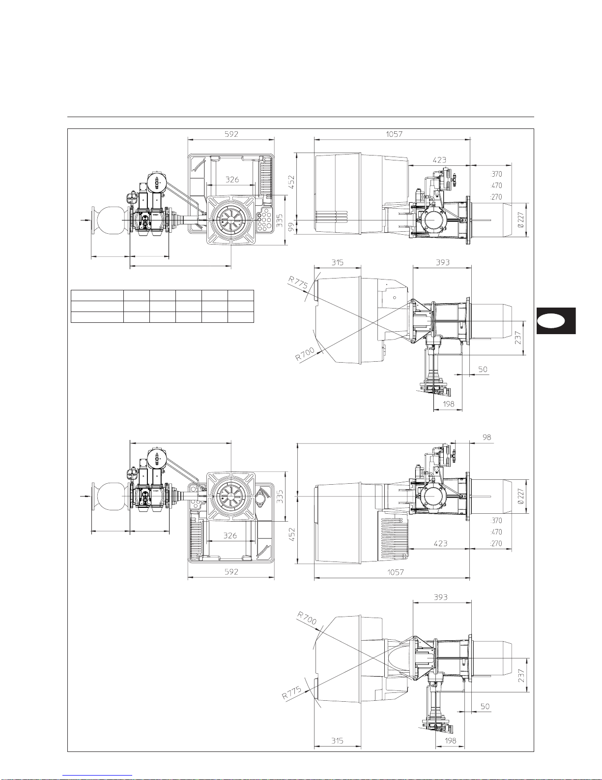
Abstände
Für Servicearbeiten ist ein freier
Abstand von min. 0,6m auf jeder Seite
des Brenners sicherzustellen.
Gasarmaturgruppe
Montage sowohl links als auch rechts
möglich.
Übersicht
Maßbild und Abmessungen
G 06.1200/1600/2100 DUO PLUS
mit Gasarmatur MBVEF 412 und MBVEF 420
DEFH
MBVEF 412 186 590 107 Rp2
MBVEF 420 — 690 — —
Page 7
7
07/2006 - Art. Nr. 13 018 114C
DE
F
F
D
E
G
H
H
KL
KM
KN
KL
KM
KN
Übersicht
Maßbild und Abmessungen
G 06.1200/1600/2100 DUO PLUS
mit Gasarmatur VGD20 - Rp2 und VGD40 - DN65
DE
Abstände
Für Servicearbeiten ist ein freier
Abstand von min. 0,6m auf jeder Seite
des Brenners sicherzustellen.
Gasarmaturgruppe
Montage sowohl links als auch rechts
möglich.
DEFGH
VGD20 Rp2 186 292 734 344 Rp2
VGD40 DN65 290 292 740 365 DN65
Page 8
07/2006 - Art. Nr. 13 018 114C
8
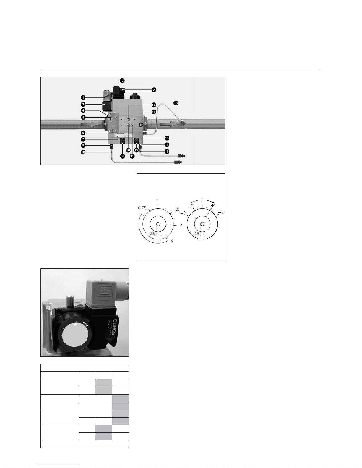
Funktion
Kompaktarmatur MBVEF
1 Elektroanschluß des
Gasdruckwächters (DIN 43650)
2 Elektroanschluß der Magnetventile
(DIN 43650)
3 Gasdruckwächter
4 Eingangsflansch
5 Druckmeßnippel R1/8,
vor Filter (beidseitig)
6 Filter (unter Deckel)
7 Typenschild
8 Anschluß Luftdruckleitung pL,
R 1/8
9 Einstellschraube für Verhältnis V
10 Druckmeßnippel pe, vor Ventil 1,
beidseitig
11 Gasdruckmeßnippel M4 nach
Ventil 2
12 Einstellschraube Nullstellung N
13 Anschluß
Feuerraumdruckleitung
pF, R1/8
14 Anschluß Gasdruckleitung pG,
R1/8
15 Ausgangsflansch
16 Druckmeßnippel pa nach
Ventil1,
beidseitig
17 Betriebsanzeige Ventile V1, V2
18 Impulsleitungen
Die Gaskompaktarmatur MBVEF ist die
Integration von Filter, Gas /
Luftverbundregler, Ventilen und
Druckwächter.
–
Feinfilter mit 0,8mm Maschenweite
–
Druckwächter GWA5
–
Servo-Druckregelteil mit
einstellbarem Verhältnis V, Korrektur
des Nullpunktes N und
Feuerraumdruckanschluß.
– Magnetventile V1, V2
schnellschließend, schnellöffnend
Eingangsdruck pe : 20-100mbar
Spannung, Frequenz : 230V, 50-60Hz.
NV
Gasdruckwächtereinstellung
·
Durchsichtigen Deckel ablegen. Die
Einstellung erfolgt über eine
Verstellscheibe mit Kreisskala und
Index x.
·
Provisorisch auf den minimalen
Skalenwert einstellen.
Brenner G 06.1600/2100 DUO PLUS
Gas: Druck ("-e)
VEF
412 420
E-Gas: 20, 25
LL-Gas: 20, 25
V
1,25
N
0
E-Gas : 100
LL-Gas: 100
V
1,25
N
0
F-Gas : 37
V
1,25
N
0
F-Gas : 50
V
1,25
N
0
Fettgedruckt : Werkslieferung
Page 9

9
07/2006 - Art. Nr. 13 018 114C
1 Elektroanschluß des
Gasdruckwächters (DIN 43650)
2 Elektroanschluß der Magnetventile
(DIN 43650)
3 Gasdruckwächter
4 Eingangsflansch
5 Druckmeßnippel R1/8, vor Filter
6 Filter (unter Deckel)
7 Typenschild
8 Anschluß Luftdruckleitung pL,
R 1/8
9 Einstellschraube für Verhältnis V
12 Einstellschraube Nullstellung N
13 Anschluß
Feuerraumdruckleitung pF, R1/8
14 Anschluß Gasdruckleitung pG,
R1/8
15 Ausgangsflansch
16 Impulsleitungen PBr, pL, pF
pBr (pG)=Impulsleitung Gas
pF = Impulsleitung Feuerraum
pL = Impulsleitung Luft
Der SKP-Regler kombiniert mit einem
VGD Ventil sichert ein konstantes
Verhältnis zwischen Gas- und
Luftdurchsatz mit einstellbarem
Verhältnis
D = Einstellschraube (Luftüberschuß)
R = Einstellschraube (Verhältnis
Gas/Luft)
Funktion
Gasarmatur VGD mit SKP 75 Regler
Gasdruckwächtereinstellung
·
Durchsichtigen Deckel ablegen. Die
Einstellung erfolgt über eine
Verstellscheibe mit Kreisskala und
Index.
·
Provisorisch auf den minimalen
Skalenwert einstellen.
Brenner G 06.1200 DUO-PLUS
Gas:Druck ("-e)
VGD
Rp2
VGD
DN65
E-Gas: 20, 25
LL-Gas: 20, 25
(Schr. R) 1,4 1,3
(Schr. D) 22
Brenner G 06.1600/2100 DUO-PLUS
Gas:Druck ("-e)
VGD
Rp2
VGD
DN65
E-Gas: 20, 25
LL-Gas: 20, 25
(Schr. R) 1,3
(Schr. D) 2
Fettgedruckt : Werkslieferung
DE
Einstell-Index
des
Verhältnisses“
R ”
Einstell-Index
des D-Wertes
Anzeige der
Gasventilöffnung
Page 10
07/2006 - Art. Nr. 13 018 114C
10
Funktion
Schaltfeld TC
Schaltfeld
Alle Steuerorgane sind von außen
sichtbar. Ein ablegbarer, durchsichtiger
Deckel, auf die Haube geklipst,
ermöglicht den Zugang zu den Steuerund Kontrollorganen für Einstellung und
Betrieb des Brenners.
Das Schaltfeld beinhaltet auch eine
Brücke zur Messung des
Flammensignals sowie die Sicherung
des Schaltkreises.
Um den Deckel abzulegen, ein- oder
beidseitig leicht eindrücken und
gleichzeitig herausziehen.
Um den Deckel wieder aufzusetzen,
beide Klipse vor die entsprechenden
Öffnungen stellen und eindrücken.
Option :
–
Betriebsstundenzähler
(Anschlußkabel bereits verdrahtet)
–
Dreipunktschrittregler RWF 40 in
genormter Einbaustelle.
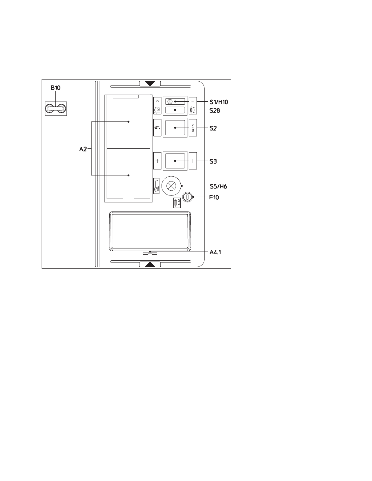
Funktion
A2 Genormte Einbaustellen 48x48
oder 48x96 mm für den Einbau
eines Leistungsreglers (Option)
A4.1 Einbaustelle mit Klips für
Anzeigeeinheit
B10 Messbrücke [µA DC] für
Zellenstrom, Anordnung neben
dem Motorschütz
F10 Sicherung
S1 Hauptschalter
0 Aus
1 Ein,
grüne Kontroll-Lampe H10
leuchtet
S2 Wahl der Leistungsregelung
K Handbetrieb
Auto Vorort-Automatikbetrieb
S3 Steht in Verbindung mit
S28J - S2K
+/- Leistungszunahme/-Abnahme
S5 Anzeige auf dem Bedienfeld :
- der Fehler (rote
Kontroll-Lampe H6 leuchtet)
- des Drucktasters zur Entriegelung
des Automaten
S28 Wahlschalter des Betriebsorts
J Vorortbetrieb
H Fernbetrieb (option)
m
Achtung :
Hauptschalter des Schaltfeldes schaltet
nur Steuerspannung. Vor Arbeiten im
Schaltteil des Brenners, diesen
komplett, incl. Drehstromanschluß
Brennermotor, vom Netz trennen.
Page 11
11
07/2006 - Art. Nr. 13 018 114C
DE
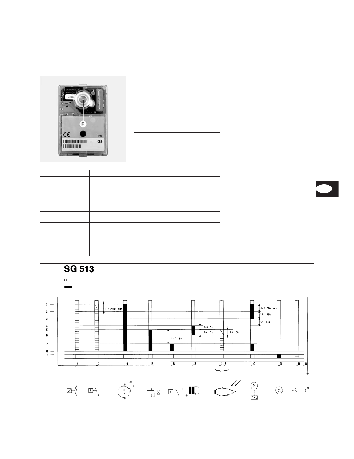
Funktion
Kenndaten des Feuerungsautomaten SG 513
Programmablauf des Feuerungsautomaten
Begrenzer Luftdruckwächter Brennermotor Gasventil Regelung Trafo Flammenwächter Stellmotor Störung Entriegelung
Erforderliche Eingangssignale
Ausgangssignale
1 Einschaltung Automat, Motor und SM
2 Prüfung auf Luftdruck
3 Ende der Vorbelüftung
4 Inbetriebsetzung Trafo und
Ende der Vorbelüftung
5 Einschaltung des Gasventils
6 Flammenüberprüfung
7 Einschaltung SM und Gasventil,
Betriebsbedingungen
0 Regelabschaltung
10 Störmodus
tlw Wartezeit Luftdruckwächter
tlk Öffnungszeit des Stellmotors und Abzug Vorbelüftung
tr Schließzeit des Servomotors
tvz Vorzündzeit
ts Sicherheitszeit
tv2 Mindestzeit zwischen Gasventil 1 und 2
Blink-Code Fehlerursache
x y y y y Kein Flammensignal nach Ablauf der Sicherheitszeit.
x x y y y Fremdlicht während Vorbelüftungs-/ Vorzündzeit
x x x y y
Luftdruckwächter: Kontakt schließt sich nicht in definierter
Zeitspanne
x x x x y
Luftdruckwächter: Kontakt öffnet sich beim Start oder im
laufenden Betrieb.
y y x x x
Luftdruckwächter nicht in Ruhestellung, z.B. weil Kontakt
verschweißt.
y y y y x Flammenausfall im laufendem Betrieb.
x x y y y — y y y y y Manuelle Störabschaltung (siehe auch Verriegelung).
Code
x
y
—
Erläuterung
Kurzes Lichtsignal
Langes Lichtsignal
Pause
Der Gasfeuerungsautomat SG 513 steuert und
überwacht den Gebläsebrenner. Durch den
mikroprozessor-gesteuerten Programmablauf
ergeben sich äußerst stabile Zeiten, unabhängig von
Schwankungen der Netzspannung oder der
Umgebungstemperatur. Der Feuerungsautomat ist
unterspannungssicher ausgelegt, dadurch wird der
Betrieb der Anlage auch bei extremen
Spannungsausfällen nicht gefährdet. Wenn die
Netzspannung unter dem geforderten Mindestwert
liegt, schaltet der Automat ohne ein Fehlersignal ab.
Nach Wiedererreichen einer normalen Spannung
läuft der Automat automatisch wieder an.
Informationssystem
Das eingebaute visuelle Informationssystem
informiert über die Ursachen einer
Störabschaltung. Die jeweils letzte
Fehlerursache wird im Gerät gespeichert und
läßt sich auch nach einem Spannungsausfall
beim Wiedereinschalten des Geräts
rekonstruieren. Im Fehlerfall leuchtet die
Leuchtdiode im Entstörknopf R permanent, bis
der Fehler quittiert, d.h. der Automat entstört
wird. Alle 10 Sekunden wird dieses Leuchten
unterbrochen und ein Blink-Code, der Auskunft
über die Störursache gibt, ausgestrahlt.
Über das als Zubehör erhältliche Auslesegerät
können dem Automaten weitere ausführliche
Informationen über Betriebs- und
Störvorgänge entnommen werden.
Verriegelung und Entriegelung
Der Automat kann über den Entstörknopf R
verriegelt (in Störung gebracht) und entriegelt
(entstört) werden, sofern am Automat
Netzspannung anliegt.
Wird der Knopf im Normalbetrieb oder Anlauf
gedrückt, so geht das Gerät in Störstellung.
Wird der Knopf im Störfall gedrückt, wird der
Automat entriegelt.
m
Vor Ein- oder Ausbau des Automaten
Gerät spannungslos machen. Das Automat
darf nicht geöffnet oder repariert werden.
Drücken Sie auf
den Knopf R
während ...
… führt zu …
… weniger als 9
Sekunden …
Entriegelung oder
Verriegelung des
Automaten.
… zwischen 9
und 13
Sekunden ...
Löschen der
Statistiken des
Automaten.
… mehr als 13
Sekunden ...
Keine Auswirkung
auf den Automat.
Page 12
07/2006 - Art. Nr. 13 018 114C
12
Montage
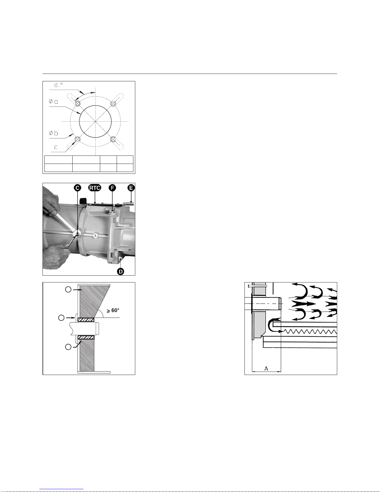
Brennermontage
Brennerrohr-Einbautiefe und
Ausmauerung
Bei Wärmeerzeugern ohne gekühlte
Vorderwand ist, sofern der
Kesselhersteller keine andere Angaben
macht, eine Ausmauerung 5 wie im
nebenstehenden Bild erforderlich. Die
Ausmauerung darf die
Flammrohrvorderkante nicht überragen
und mit maximal 60° konischzulaufen.
DerLuftspalt zwischen Ausmauerung
und Brennerrohr ist mit einem
elastischen, nicht brennbarem
Isolationsmaterial 6 auszufüllen. Bei
Kesseln mit Umkehrfeuerung ist die
minimale Eintauchtiefe A des
Brennerrohres gemäß Angaben des
Kesselherstellers zu beachten.
5
4
6
Ø a (mm) Ø b (mm) c d
250
300 bis 400
M12 45°
Montage Brennkopf
·
Brennerplatte/Kesseltüre gemäß
nebenstehender Zeichnung
vorbereiten.
·
Innendurchmesser a Ø 250 mm
festlegen.
·
Für die Brennkopfflanschbefestigung
sind 4 Bohrungen M12
(Lochkreisdurchmesser 300-400
mm) gemäß nebenstehender
Zeichnung erforderlich.
·
Stehbolzen M12 in die
Brennerplatte/Kesseltüre
einschrauben und die
Isolationsunterlage aufsetzen. Bei
Lochkreis <400 mm vorgestanzte
Langlöcher auf das erforderliche
Maß ausschneiden.
·
Brennkopf mit 4 Sechskantmuttern
M12 befestigen.
·
Der Raum zwischen Flammrohr und
Türisolierung ist mit feuerfestem
Material auszukleiden
Achtung:
die Feuerraumdruckabnahmeleitung
pF darf nicht verstopft werden.
Montage Brennergehäuse
Hängt das Brennergehäuse unter der
Brennkopfachse, ist wie folgt
vorzugehen.
·
Brennergehäuse auf Brennkopf
mittels fester (gegenüber dem
Gasanschluß) Achse F befestigen.
· Mischeinrichtung einbauen und mit
seitlicher Schraube C anziehen
(Kontermutter M10 und
Inbusschraube).
· Die zwei Zündabel und das
Ionisationskabel anschließen.
· Brenner mit Achse E schließen.
· Sicherungsschraube D anziehen.
Falls erforderlich kann das Gehäuse
über die Brennerkopfachse montiert
werden.
Andere Brennergehäusestellungen sind
nicht möglich.
Page 13
13
07/2006 - Art. Nr. 13 018 114C
Montage
Gasarmaturmontage
Dichtheitskontrollgerät VPS 504 S01
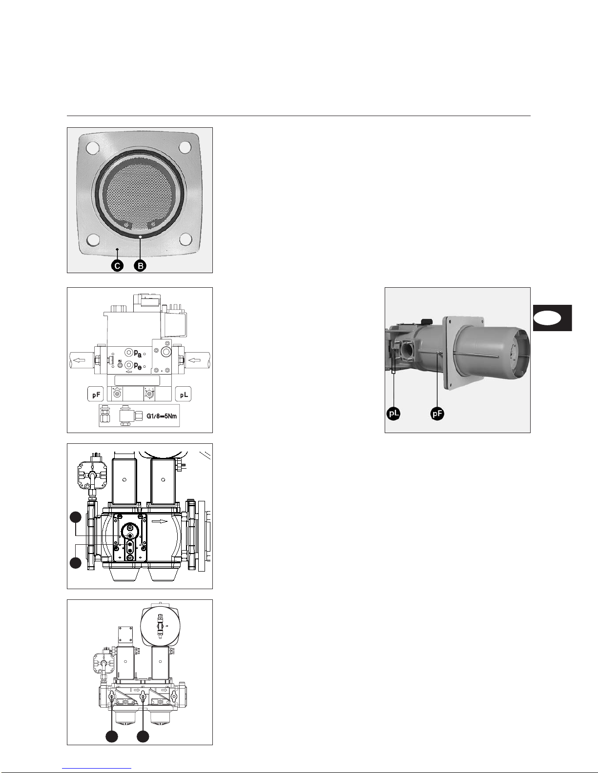
Montage Gasarmatur SKP75/MBVEF
·
Die richtige Einbaulage des
O-Ringes B im Gasanschlußflansch
C überprüfen.
·
Die Gasarmatur mit Muttern M10 so
befestigen, daß der SKP-Regler
oder die Magnetspulen der MBVEF
unbedingt senkrecht über der
Gasarmatur liegen.
·
Die mitgelieferten, gekennzeichneten
Impulsleitungen pF, pL und pG für
linken oder rechten Gasanschluß
montieren.
·
Bei SKP 75 das mitgelieferte
Sicherheitsmagnetventil (Bausatz)
mit Spule nach oben montieren, den
mitgelieferten Gasfilter (Bausatz)
waagerecht mit obenliegendem
Deckel (2 Messanschlüsse)
einbauen.
·
Fließrichtung beachten.
·
Ein thermisch auslösendes
Sicherheitsventil und einen
Gaskugelhahn (bauseits) vor der
Gasarmatur montieren.
Anschluß der Druckabnahmeleitungen
·
Die zwei Stopfen pF und PL auf
dem Zwischenrohr abnehmen.
·
Die zwei verbundenen
Rohrverbinder mit einem
zugelassenen Dichtungsmittel auf
den Gasdruckleitungen pF und pL
montieren.
· Die Verbindungen zwischen Ventil
und Zwischenrohr für eine rechts
liegende Gasarmatur mit den
Leitungen pF und pL, für eine links
eingebaute Gasarmatur mit den pF
und pL “links” bezeichneten
Leitungen herstellen.
· Später auf Dichtheit prüfen.
Einbau des Dichtheitskontrollgeräts
VPS 504 S01 auf MBVEF/VGD40
·
Die zwei Schrauben pa und pe auf
Ventil MBVEF, auf Ventil VGD40 die
Schraube 1 und 2.
·
Darauf achten, daß die zwei
O-Ringe auf dem
Dichtheitskontrollgerät vorhanden
sind.
·
Das Gerät VPS504 mit den vier
mitgelieferten selbstschneidenden
Schrauben befestigen.
·
Elektrische Verbindung mittels 7P
Stecker herstellen.
·
Auf Dichtheit prüfen.
Einbau des Dichtheitskontrollgeräts
VPS 504 S01 auf VGD20 :
·
Die zwei Schrauben 3 und 4
entfernen.
·
Doppelnippel einschrauben.
·
Verrohrungsset und
Anschlußadapter montieren.
·
VPS504 und Anschlußadapter mit
den vier mitgelieferten
selbstschneidenden Schrauben
befestigen.
·
Darauf achten, daß die zwei O-Ringe
auf dem Dichtheitskontrollgerät
vorhanden sind.
·
Elektrische Verbindung mittels 7P
Stecker herstellen.
·
Auf Dichtheit prüfen.
1
2
DE
3 4
Page 14
07/2006 - Art. Nr. 13 018 114C
14
4
Montage
Kontrolle Mischeinrichtung
Sekundärluft
Einstellung Mischeinrichtung für Erdgas / Flüssiggas
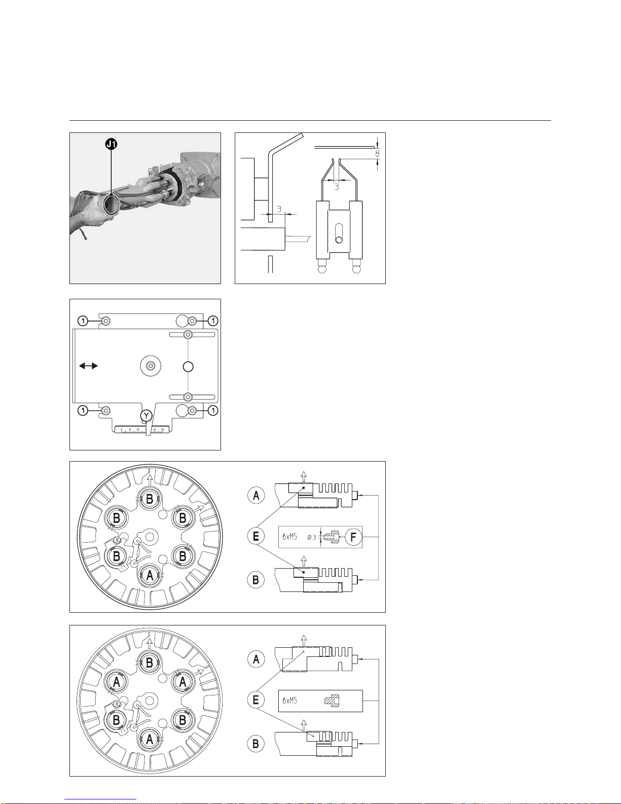
Kontrolle Mischeinrichtung
·
Sicherungsschraube D lösen (S.
Seite 12).
·
Mobile Achse E entfernen.
·
Brennergehäuse öffnen.
·
Zünd- und Ionisationskabel lösen.
·
Die vier Schrauben der Einstellplatte
(RTC) um 2 Umdrehungen lösen.
·
Andruckschraube C lösen.
·
Mischeinrichtung herausziehen.
·
Einstellungender Zündelektroden und
der Ionisationssonde / Stauscheibe
überprüfen und justieren.
·
In umgek. Reihenfolge wieder einbauen.
·
Zustand und Position der Ringdichtung
J1 bei der Montage prüfen.
·
Dichtheit kontrollieren.
Sekundärluft
Mit Sekundärluft wird der Luftdurchsatz
zwischen Flammrohr und Stauscheibe
bezeichnet.
Die Stellung der Stauscheibe (Maß Y)
kann an der Skala der Einstellplatte
RTC abgelesen werden. Die Pos. 50
entspricht der max.
Sekundärluftmenge und 0 der min.
Menge. Bei der Anlieferung des
Brenners ist das Maß Y auf 30mm bzw.
35mm eingestellt.
Abhängig von Brennerleistung und
Anlagenbedingungen kann zur
Optimierung der Zündqualität und der
Verbrennungswerte eine Nachstellung
erforderlich sein.
Einstellung
Die Einstellung kann während des
Brennerbetriebs erfolgen.
Grundeinstellwerte sind in Tabelle Seite
20 abhängig von der Brennerleistung
angegeben.
· Die zwei Schrauben 2 (Zeichnung)
lösen.
· Die Einheit in die gewünschte
Richtung bringen.
Empfohlene Einstellung für Erdgas
Auf der mit A bezeichnete Gasdüse
sind 5 nach außen und 1 nach innen
gerichteter Schlitz durch die
Schiebehülse E offen zu halten.
Befestigung der Stauscheibe durch 6
gebohrte M5x6 Schrauben F.
Auf den mit B bezeichneten Gasdüsen
sind 5 nach außen und 0 nach innen
gerichtete Schlitze durch die
Schiebehülsen E offen zu halten.
Empfohlene Einstellung für
Flüssiggas
Auf den mit A bezeichneten Gasdüsen
sind 3 nach außen und 1 nach innen
gerichteter Schlitz durch die
Schiebehülse E offen zu halten.
Befestigung der Stauscheibe durch 6
ungebohrte M5x6 Schrauben.
Auf den mit B bezeichneten Gasdüsen
sind 3 nach außen und 0 nach innen
gerichteter Schlitz durch die
Schiebehülsen E offen zu halten.
Ionisationssonde / Zündelektrode
Page 15
15
07/2006 - Art. Nr. 13 018 114C
Montage
Gasversorgung
Elektrische Versorgung
Prüfung vor Inbetriebnahme
Die Elektroinstallation und
Anschlussarbeiten werden
ausschließlich vom
Elektrofachmann ausgeführt. Die
VDE- und EVU-Vorschriften und
Bestimmungen sind dabei zu
beachten (RGIE-AREI für Belgien).
Elektrischer Anschluss
· Überprüfen, ob Netzspannung der
angegebenen Betriebsspannung von
230/400 V, 50 Hz Drehstrom mit
Nulleiter und Erdung entspricht
Brennerabsicherung: 10A
Elektrische Steckverbindung
Brenner und Wärmeerzeuger (Kessel)
werden über siebenpolige und
vierpolige Steckverbindungen
miteinander verbunden.
Anschluss der Gasarmatur mit den
sich am Brenner befindlichen Steckern
herstellen
Anschluß Brennermotor
Der Brenner wird für eine
Netzspannung von 400V-50Hz
Drehstrom mit Nulleiter und Erdung
geliefert.
Das Anschlußkabel für den
Brennermotor muß durch die
Kabelverschraubungen geführt und an
der Klemmleiste gemäß Elektroschema
verdrahtet werden. Drehrichtung
Gebläsemotor (siehe Pfeil am
Brennergehaüse) über Handbetätigung
des Brennerschützes prüfen.
Prüfung vor der Inbetriebnahme
Vor der Inbetriebnahme des Brenners
sind folgende Prüfungen bzw.
Kontrollen durchzuführen.
–
Betriebsvorschriften des
Wärmeerzeuger-Herstellers
–
Einstellung von
–
Temperaturregler
–
Druckregler
–
Begrenzer
–
Sicherheitswächter
–
Gasanschlußdruck min. 20mbar
Fließdruck
–
Dichtheit der gasführenden
Elemente
–
Entlüftung der brennstofführenden
Leitungen
–
Offene Abgaswege, ausreichende
Frischluftzufuhr.
–
Drehrichtung Gebläsemotor (siehe
Pfeil am Brennergehäuse).
Prüfung des Brenner Programmablaufes vor der ersten Gasfreigabe
·
Handabsperrventil vor der
Gas-Kompakteinheit schließen.
·
Steht kein ausreichender Gasdruck
vor der Gaskompaktarmatur an, ggf.
Gasdruckwächter brücken (Klemme
2 und 3), hierzu Brenner
spannungsfrei machen.
·
Brenner durch Einschalten des
Wärmeerzeugers starten und
Programmablauf prüfen.
·
Gebläse läuft an.
·
Vorbelüftungszeit (54s)
·
Vorzündzeit (3s)
·
Magnetventile öffnen
·
Sicherheitszeit (3s)
·
Störabschaltung nach Ablauf der
Sicherheitszeit mit Verriegelung des
Feuerungsautomaten (Störlampe
leuchtet)
·
Brenner durch Trennen des
Elektroanschlußes spannungsfrei
machen und ggf. Drahtbrücke
Gasdruckwächter entfernen.
·
Elektroanschluß wieder herstellen.
·
Feuerungsautomat durch Drücken
des Entriegelungsknopfes R entriegeln.
Allgemeine Vorschriften für die
Gasversorgung
·
Der Anschluss der Gasarmatur an
das Gasnetz darf nur von einer
anerkannten Fachkraft durchgeführt
werden.
·
Der Gasleitungsquerschnitt muss so
gestaltet werden, dass der
vorgeschriebene Gasfließdruck nicht
unterschritten wird.
Bei der Inbetriebnahme des Brenners
wird gleichzeitig die Anlage unter der
Verantwortung des Installateurs oder
seines Stellvertreters abgenommen. Er
allein kann gewährleisten, dass die
Anlage den geltenden Normen und
Vorschriften entspricht.
Der Installateur muss im Besitz einer
vom Gaswerk ausgestellten Zulassung
sein und die Anlage auf Dichtheit
geprüft und entlüftet haben.
DE
Page 16

07/2006 - Art. Nr. 13 018 114C
16
Inbetriebnahme
Brennereinstelldaten
Luftregulierung
Gasdruckwächter
·
Durchsichtigen Deckel ablegen.
·
Die Einstellung erfolgt über eine
drehbare Einstellskala und einen
Index x
·
Provisorisch auf den Minimalwert
der Skala einstellen.
Luftdruckwächter
·
Durchsichtigen Deckel ablegen.
·
Das Gerät beinhaltet eine mobile
Scheibe mit Skala und ein Index x.
·
Luftdruckwächter provisorisch auf
Minimalwert der Scheibe einstellen.
Typ
Brenner-
leistung
kW
Maß
Y
mm
Luftklappenstellung (°)
Zündlast
Nocke III
Vollast
Nocke I
G 06.1200 DUO PLUS
700 25 10 35
900 30 10 45
1100 35 10 50
1200 40 10 60
G 06.1600 DUO PLUS
1100 35 10 50
1300 45 10 80
1600 50 10 90
G 06.2100 DUO PLUS
1150 25 10 55
1400 30 10 65
1700 35 10 80
1900 50 10 85
2100 50 10 90
Obige Einstelldaten sind Grundeinstellungen. Die Werkseinstelldaten sind fett umrandet. Mir diesen Einstellungen kann im
Normalfall der Brenner in Betrieb genommen werden. Überprüfen Sie in jedem Fall sorgfältig die Einstellwerte. Es können
anlagenbedingte Korrekturen notwendig sein.
Die Luftregulierung im Brennkopf
beeinflusst neben der Luftmenge auch
die Mischzone und den Luftdruck im
Brennerrohr.
·
Maß Y entsprechend vorstehender
Einstelltabelle einstellen.
Dazu :
·
Schrauben 2 lösen.
·
RTC Platte schieben :
–
rückwärts = mehr Luft
–
vorwärts = weniger Luft
m
Schrauben 1 nicht berühren.
Die Regulierung der Verbrennungsluft
erfolgt durch zwei Parameter :
·
Luftregulierung im Brennkopf über
den Öffnungsspalt zwischen
Stauscheibe und Brennerrohr.
·
Luftregulierung über Luftklappe,
angetrieben durch Stellmotor Y10.
4
Page 17
17
07/2006 - Art. Nr. 13 018 114C
Inbetriebnahme
Luftregulierung
Luftregulierung über Luftklappe
Diese wird über den Stellmotor Y10
angetrieben.
Die Position der Luftklappe wird durch
Einstellung der Nocken I - IV festgelegt.
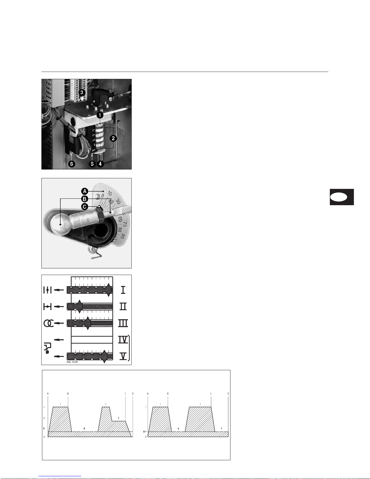
1 Stellindex der Nocken
2 Vier einstellbare Nocken
3 Schlüssel zur Nockeneinstellung
4 Scheibe mit Skala ;
gibt Stellung der Luftklappe an
5 Knopf zur Entkupplung der
Luftklappe von Stellantrieb
6 Anschlußleiste
A Skala (0° bis 90°) gibt Stellung
des Stellantriebs an
B Kupplung zwischen Luftklappe
und Stellantrieb
C Stellindex der Luftklappe
Kontrolle der Luftklappenstellung
Die Luftklappenstellung kann an der
Skala A des Luftklappenantriebes
abgelesen werden.
Bei Über-Kopf-Montage des Brenners
kann die Luftklappenstellung an der
Skalenscheibe 4 abgelesen werden.
Funktion der Nocken
Nocke Funktion
I Vollast
II Abschluß bei Stillstand
III Zündlast
IV Nicht einstellbar und abhängig
von Nocke V
V Min. Regulierungslast
Funktionsablauf
A-B Vorbelüftung
B-C Leistungsregulierung
C-D Regelabschaltung
Einstellung
Nocken von Hand oder mit
beiliegendem Schlüssel entsprechend
der gewünschten Brennerleistung und
den in der Einstelltabelle angegebenen
Werten voreinstellen.
·
Nocken von Hand oder mit
beiliegendem Schlüssel
entsprechend der gewünschten
Brennerleistung und den in der
Einstelltabelle angegebenen Werten
voreinstellen.
·
Wenn keine unterschiedliche
Einstellung zwischen Zündlast und
Kleinlast notwendig ist, Nocke V und
Nocke III auf gleichen Wert
einstellen (Bild rechts).Wird eine
Einstellung der Kleinlast oberhalb
der Zündlast benötigt, Nocke V
größer Nocke III einstellen. Nach
dem ersten Hochregeln des
Brenners übernimmt Nocke V die
Funktion der Kleinlastbegrenzung
(Bild links).
V > III V = III
DE
Page 18

07/2006 - Art. Nr. 13 018 114C
18
Einregulierung des Brenners
·
Gaskugelhahn öffnen.
·
Gas- und Luftdruckwächter auf
Minimalwerte einstellen.
·
Mikroamperemeter (0-500µA)
anstelle der Meßbrücke anschließen
(Polarität prüfen).
·
Die Kippschalter S1/H10.1 - S29JS2K drücken.
·
Kesselregelung einschalten.
·
Feuerungsautomat entriegeln.
·
Nach Flammenbildung die
Verbrennungswerte kontrollieren
(CO,CO
2
).
·
Ionisationsstrom ablesen
(Sollwertmin. 8µA).
·
Gasdurchsatz am Gaszähler
ablesen.
·
Leistung, durch Drücken auf + des
Impulschalters S3, auf Großlast
erhöhen.
·
Abgaswerte kontrollieren. Je nach
Meßwert das Gas/Luftverhältnis
nachjustieren :
– bei SKP auf Einstellschraube R
einwirken. Dazu obere
Abdeckhaube entfernen. Höheres
CO
2
in Richtung +. Niedrigeres
CO
2
in Richtung -.
(s. Symbole Oberseite SKP75
Seite 9)
–
bei MB VEF Ventil auf Schraube V
wirken. Höheres CO
2
in Richtung
grösserer Skalenwert. Niedrigeres
CO
2
in Richtung kleinerer
Skalenwert. (s. Seite 8)
·
Um den gewünschten Wirkungsgrad
zu erreichen, die vom
Kesselhersteller angegebenen
CO
2
-und Abgastemperaturwerte
einhalten.
·
Ionisationsstrom ablesen (Sollwert
min. 8µA ).
·
Gasdurchsatz am Gaszähler
ablesen.
·
Brenner auf Kleinlast bringen und
Verbrennungswerte kontrollieren. Je
nach Meßwert, beim SKP-Regler die
Schraube D, beim MB VEF Regler
die Schraube N justieren.
·
Die gewünschte Teillast mit der
Taste S3 festlegen. Dazu ist die
Nocke V am Luftklappenstellantrieb
je nach Bedarf nachzujustieren.
· Abgaswerte nochmals kontrollieren
und je nach Messwert das Gas/Luft
Verhältnis nachjustieren.
· Brenner wieder auf Großlast
bringen; die Verbrennungswerte
kontrollieren.
·
Haben sich die Meßwerte durch
Verstellen der Schraube D beim
SKP-Regler oder der Schraube N
beim MB VEF-Ventil geändert,
müssen beim SKP-Regler das
Verhältnis R, beim MB VEF-Ventil
das Verhältnis V im gewünschten
Sinne nachjustiert werden.
·
Muß die Brennkopfeinstellung (Maß
Y) geändert werden, so ist der
ganze Einstellvorgang nochmals
vorzunehmen.
Sind die Verbrennungswerte korrekt, ist
bei Kleinlast und Großlast wie folgt
vorzugehen:
·
Die Gasdurchsätze durch Verstellen
der Nocken V und I des Stellmotors
justieren.
·
Gasdurchsätze am Gaszähler
prüfen.
Einstellung Zündlast
Die Zündlast mit Nocke III so einstellen,
daß ein sicherer Start des Brenners
gewährleistet ist.
Zündlast muß so eingestellt werden,
daß keine Kondensation im Kessel
auftritt.
Inbetriebnahme
Einregulierung des Brenners
Einstellung Gasdruckwächter, Luftdruckwächter
Funktionskontrolle
Einstellung Gasdruckwächter
·
Zur Einstellung Abschaltdruckes : Deckel
des Gasdruckwächters abnehmen.
·
Brenner starten und Gasdruck vor
Armatur durch androsseln des
Kugelhahns auf gewünschten
Abschaltwert einstellen.
·
Einstellscheibe im Uhrzeigersinn drehen,
bis Gasdruckwächter Brenner abschaltet.
Einstellung Luftdruckwächter
·
Brenner auf Kleinlast einstellen.
·
Skalenwert solange erhöhen bis
Luftdruckwächter Brenner abschaltet.
·
Luftdruckwächter auf 70%des
Abschaltwertes einstellen.
Funktionskontrolle
Eine Sicherheitstechnische Überprüfung
der Flammenüberwachung muss sowohl
bei der erstmaligen Inbetriebnahme wie
auch nach Revisionen oder längerem
Stillstand der Anlage vorgenommen
werden.
–
Anlaufversuch mit geschlossenem
Gasventil : nach Ende der
Sicherheitszeit muss der
Feuerungsautomat auf Störung gehen !
–
Normaler Anlauf ; wenn Brenner in
Betrieb, Gasventil schließen : nach
Flammenausfall muss der
Feuerungsautomat auf Störung
gehen !
–
Normaler Anlauf ; während
Vorbelüftung oder Betrieb
Luftwächterkontakt unterbrechen :
Feuerungsautomat muss sofort auf
Störung gehen !
–
Vor Anlauf Luftdruckwächter
überbrücken : Brenner schaltet für
ca. 2-3 sec. ein, anschließend
erfolgt Störabschaltung. Nach 10
sec. wird diese Kurzstörung vom
Automaten selbsttätig zurückgesetzt
und ein zweiter Anlaufversuch
erfolgt (Motor schaltet für 2-3 sec.
ein). Ist der LW-Kontakt immer noch
geschlossen (z.B. verschweißt)
erfolgt eine echte Störabschaltung.
Hat der LW-Kontakt jedoch
innerhalb dieser 10 sec. geöffnet
(z.B. durch auslaufenden Motor),
erfolgt ein normaler Betriebsanlauf.
Page 19

19
07/2006 - Art. Nr. 13 018 114C
Service
Wartung
Servicearbeiten an Kessel und
Brenner führt ausschließlich die
geschulte Fachkraft durch. Um eine
turnusgemäße Durchführung der
Servicearbeiten zu gewährleisten
sollte dem Betreiber der Anlage der
Abschluß eines Wartungsvertrages
empfohlen werden.
m
·
Vor Wartungs- und
Reinigungsarbeiten, Strom
abschalten.
·
Handabsperrventil schließen
·
Originalersatzteile verwenden.
Kontrolle der Abgastemperatur
·
Abgastemperatur überprüfen.
·
Kessel reinigen, wenn die
Abgastemperatur den Wert der
Inbetriebnahme um mehr als 30K
überschreitet.
A1 Feuerungsautomat
B10 Ionisationsbrücke
F6 Luftdruckwächter
F12 Motorschutzrelais
K1 Motorschutz
K4 Relais
M1 Brennermotor
T1 Zündtransformator (verdeckt)
TC Schaltfeld
Y10 Stellantrieb Luftklappe
8 Flammrohr
113 Luftkasten
Kontrolle der Zündelektroden und
der Mischeinrichtung
·
Sicherungsschraube D lösen.
·
Mobile Achse E entfernen.
·
Brennergehäuse öffnen.
·
Zünd und Ionisationskabel lösen.
·
Die vier Schrauben der Einstellplatte
(RTC) um 2 Umdrehungen lösen.
·
Andruckschraube C lösen.
·
Mischeinrichtung herausziehen.
·
Einstellungen der Zündelektroden
und der Stauscheibe überprüfen und
justieren.
·
In umgekehrter Reihenfolge wieder
einbauen.
·
Zustand und Position der
Ringdichtung J1 bei der Montage
prüfen.
·
Dichtheit kontrollieren.
Reinigung des Lüfterrades
·
Motor durch Trennen des
Elektroanschlusses spannungsfrei
machen.
·
Die 7 Schrauben der Motorplatine
herausdrehen.
·
Platine mit Motor sorgfältig ablegen
ohne die Druckabnahmeleitung des
Luftdruckwächters zu beschädigen.
·
Die Luftdruck-Leitungen “trocken”
reinigen.
·
Kein Druckmedium verwenden.
·
Die 4 Befestigungsschrauben des
Luftleitschnabels entfernen.
·
Luftkanal und Lüfterrad gründlich
reinigen.
·
Wieder zusammenbauen.
DE
Page 20

07/2006 - Art. Nr. 13 018 114C
20
Service
Wartung
Flammrohr demontieren
Dieser Arbeitsvorgang macht entweder
das Öffnen der Feuerraumtür oder die
Demontage des Brenners erforderlich.
–
Variante 1 -Zugang über die
Feuerraumtüre
·
Andruckschraube C lösen.
·
Zünd/Mischeinrichtung demontieren
·
Die 3 Befestigungsschrauben an der
Flammenrohraufnahme von Innen
mit 1 bis 2 Umdrehungen lösen.
Achtung: Schrauben haben
Linksgewinde (Inbus 3).
·
Feuerraumtür öffnen.
·
Flammrohr herausziehen,
überprüfen, reinigen und ggfs. bei
Deformation austauschen.
·
In umgekehrter Reihenfolge wieder
einbauen.
·
Den Raum zwischen Flammrohr und
Türisolierung mit feuerfestem
Material auskleiden.
·
Feuerraumtür schließen.
–
Variante 2 - Demontage des
Brenners
· Andruckschraube C lösen.
· Zünd/Mischeinrichtung demontieren
· Elektroanschlüsse lösen.
· Gasarmaturgruppe demontieren.
· Gasanschluß abschrauben
(4 Muttern M8).
· Brennergehäuse demontieren und
ablegen; dazu Sicherungsschraube
D lösen, Achsen E und F entfernen.
Elektrische Kabel nicht beschädigen.
·
Brennkopf abschrauben und dann
wie unter Variante 1 vorgehen.
·
In umgekehrter Reihenfolge wieder
einbauen.
Ventile
Die Ventile erfordern keine besondere
Wartung.
Es ist keine Reparatur an einem Ventil
gestattet.
Defekte Ventile müssen durch eine
qualifizierte Fachkraft ersetzt werden,
die nachträglich eine Dichtheits-,
Funktions- und Verbrennungskontrolle
durchführen muß.
Filteraustausch Gas
Der Filtereinsatz muß einmal jährlich
kontrolliert und wenn verschmutzt
ausgetauscht werden.
·
Deckelbefestigungsschrauben am
Filter, Vorbaufilter oder am Multibloc
lösen.
·
Filtereinsatz herausziehen; kein
Schmutz im Filter stehen lassen.
·
Neuen Filtereinsatz einlegen.
·
Deckel mit Schrauben wieder fest
montieren.
·
Handabsperrhahn öffnen; Dichtheit
kontrollieren.
Haubenreinigung
·
Haube mit Wasser und Waschmittel
reinigen.
·
Chlorhaltige und abschleifende Mittel
sind zur Brennerhaubenreinigung zu
unterlassen.
Wichtig
· Nach jedem Eingriff sind die
Verbrennungswerte bei
Betriebsbedingungen zu
kontrollieren (geschlossene
Heizraumtür, montierte Haube,
usw.).
· Messwerte in die
Heizraumdokumente eintragen.
Page 21

21
07/2006 - Art. Nr. 13 018 114C
Service
Störungsbeseitigung
Ursachen und Beseitigung von
Störungen
Bei Störungen müssen die
grundsätzlichen Voraussetzungen zum
ordnungsgemäßen Betrieb kontrolliert
werden:
1. Ist Strom vorhanden ?
2. Ist Gasdruck vorhanden ?
3. Ist Gasabsperrhahn geöffnet ?
4. Sind alle Regel- und
Sicherheitsgeräte, wie
Kesselthermostat,
Wassermangelsicherung,
Endschalter usw. richtig
eingestellt ?
Wenn die Störung weiter besteht:
·
Die vom Feuerungsautomat
abgegebenen Blink-Codes beachten
und ihre Bedeutung aus
nachstehender Tabelle entnehmen.
Mit dem als Zubehör erhältlichen
Visualisierungsprogramm
MDE
®
-ELCOSCOPE können dem
Automaten weitere ausführliche
Informationen über Betriebs- und
Störvorgänge entnommen werden.
Alle sicherheitsrelevanten Komponenten
dürfen nicht repariert werden, sondern
müssen durch Teile mit derselben
Bestellnummer ersetzt werden.
m
Nur Originalersatzteile
verwenden.
Hinweis:
Nach jedem Eingriff:
·
Unter echten Betriebsbedingungen
(Türen geschlossen, Haube montiert
usw.) die Verbrennung kontrollieren
sowie die einzelnen Leitungen auf
Dichtheit prüfen.
·
Die Ergebnisse in den
entsprechenden Unterlagen
dokumentieren.
Störung Ursache Abhilfen
Brenner startet nach Thermostatanforderung
nicht.
Keine Störungsanzeige am Feuerungsautomat.
Ab- oder Ausfall der Versorgungsspannung.
Störung des Automaten.
Ursprung des Absinkens oder des Mangels
an Spannung überprüfen.
Automat austauschen.
Brenner läuft nicht an.
Gasdruck normal
Luftdruckwächter in Ordnung
keine Wärmeanforderung
ungenügender Gasdruck
Gasdruckwächter verstellt oder defekt
Luftdruckwächter nicht in Ruhestellung
Thermostate defekt oder verstellt
Gasleitungen prüfen.
Filter reinigen.
Gasdruckwächter überprüfen oder
Gaskompakteinheit austauschen.
Luftdruckwächter einstellen, austauschen.
Thermostate einstellen oder austauschen.
Brenner startet bei Einschaltung ganz kurz,
schaltet ab und gibt folgendes Signal:
x x y y y - y y y y y
Automat wurde absichtlich abgeschaltet. Automat entriegeln.
Brenner läuft nicht an.
y y x x x
Luftdruckwächter : nicht in Ruhestellung
Falsche Einstellung
Kontakt verschweißt
Druckwächter neu einstellen.
Druckwächter austauschen.
Brenner-Gebläse läuft an. Brenner startet nicht.
x x x y y
Luftdruckwächter: Kontakt schließt nicht. Druckwächter überprüfen undVerdrahtung
kontrollieren. Druckwächter neu einstellen.
Brenner stoppt aus laufendem Betrieb.
x x x x y
Luftdruckwächter: Kontakt öffnet sich beim
Start oder im laufenden Betrieb.
Druckwächter einstellen oder austauschen.
Brenner-Gebläse läuft an. Brenner startet nicht.
x x y y y
Streulicht bei der Vorbelüftung oder
Vorzündung.
Ventil austauschen.
Brenner läuft an, Zündung schaltet ein, dann
Abbruch
x y y y y
Keine Flamme nach Ablauf der Sicherheitszeit.
Gasdurchsatz falsch eingestellt.
Störung im Flammenüberwachungskreis
Kein Zündbogen.
Elektrode(n) kurzgeschlossen.
Zündkabel beschädigt oder defekt.
Zündtrafo defekt.
Feuerungsautomat.
Magnetventile öffnen sich nicht.
Gasdurchsatz regeln.
Zustand und Stellung der Ionisierungssonde
gegenüber der Masse überprüfen.
Zustand und Anschlüsse des
Ionisierungskreises überprüfen (Kabel und
Meßbrücke).
Zündelektrode(n) einstellen, reinigen, ggf.
ersetzen.
Zündkabel anschließen oder ersetzen.
Trafo ersetzen.
Automat austauschen.
Verkabelungen zwischen Automat und externen
Komponenten kontrollieren.
Spule überprüfen oder austauschen.
Ventil prüfen/ersetzen.
Brenner stoppt aus laufendem Betrieb.
y y y y x
Ausfall der Flamme im laufenden Betrieb. Kreis der Ionisierungssonde überprüfen.
Feuerungsautomat überprüfen oder
austauschen.
DE
Page 22

07/2006 - Art. Nr. 13 018 114C
22
Overview
Contents
Page
Overview Contents. . . . . . . . . . . . . . . . . . . . . . 22
Important notes . . . . . . . . . . . . . . . . . . 22
Technical data, power graphs . . . . . . . . . . 23
Selection of gas valve assembly . . . . . . . . . 24
Burner description. . . . . . . . . . . . . . . . . 25
Dimensions . . . . . . . . . . . . . . . . . . 26-27
Function Compact valve assembly . . . . . . . . . . . 28-29
TC control panel. . . . . . . . . . . . . . . . . . 30
Control unit . . . . . . . . . . . . . . . . . . . . 31
Installation Burner assembly . . . . . . . . . . . . . . . . . 32
Assembly of the gas valve assembly,
leak controller . . . . . . . . . . . . . . . . . . . 33
Checking / Setting . . . . . . . . . . . . . . . . 34
Burner head for natural gas / Propane gas . . . . 34
Gas supply, electrical supply . . . . . . . . . . . 35
Pre-startup check . . . . . . . . . . . . . . . . . 35
Startup Burner adjustment data . . . . . . . . . . . . . . 36
Airflow control . . . . . . . . . . . . . . . . . 36-37
Burner adjustment . . . . . . . . . . . . . . . . 38
Air pressure switch /Gas pressure switch setting . 38
Checking for correct functioning. . . . . . . . . . 38
Servicing Maintenance . . . . . . . . . . . . . . . . . 39-40
Troubleshooting . . . . . . . . . . . . . . . . . . 41
Declaration of conformity for
forced-draught gas burners
We, factory certified with Nr. AQF 030,
F-74106 ANNEMASSE Cedex
declare under our sole responsibility
that the products
VECTRON G 06.1200 DUO PLUS
VECTRON G 06.1600 DUO PLUS
VECTRON G 06.2100 DUO PLUS
conform to the following standards:
EN 60335
EN 50081
EN 50082
EN 676
In accordance with the stipulations of
directives
89 / 396/EEC gas devices
89 / 336/EEC EMC directive
73 / 23 /EEC low-voltage devices
directive
92 / 42 /EEC working efficiency
directive
97 / 23 /EEC pressure equipment
directive
These products bear the CE marking.
Annemasse, January 1st 2004
J.HAEP
Description of burner
The burners VECTRON
G 06.1200/1600/2100 DUO PLUS are
modulating burners in a monoblock
configuration. Within their
corresponding power range, they are
suitable for use with all heat generators
designed to conform to EN303.
For any other use, the agreement of
ELCO must be asked for.
Important notes
The design and function of this burner
both conform to EN 676 standards.
All installation, initial-startup and
maintenance work must be carried out
by authorised service engineers, who
should observe all relevant guidelines,
directives and specifications.
The installation of the gas conduits and
valve assemblies should likewise be
carried out in conformity with the
applicable directives and regulations
(e.g. DVGW-TRGI 1986/96 ; TRF 1988 ;
DIN 4756).
All seals and sealing material used
must be DVGW (ARGB-KVBG for
Belgium) tested and approved. Check
seals and connection points for
possible leaks with a suitable
non-corrosive foam product.
Bleed the gas conduit before using for
the first time. DO NOT bleed via the
furnace. Servicing work on switches,
limiting devices and control units along with other safety devices - MUST
be carried out by the supplier of each
individual item, or by its authorised
service engineers. Original parts may
only be replaced by an authorised
service engineer.
EN 676
Forced-draught gas burner
EN 60335-2
Safety of electrical devices designed for
domestic use
Gas conduits and valve assemblies
must be installed in accordance with
DVGW-TVR/TRGI (gas).
Place of installation
The burner must not be operated in the
presence of corrosive fumes (e.g.
hairspray, tetrachloroethylene or carbon
tetrachloride), large amounts of dust, or
high levels of air humidity (e.g. in
laundry rooms). Ensure that a
ventilation inlet of the following
characteristics is provided:
DE : up to 50kW: 150cm
2
for each additional kW: + 2,0cm
2
CH : up to 33kW : 200 cm²
for each additional kW: + 6,0cm
2
.
Rules may vary according to local
legislation.
Scope of delivery
The burner assembly is supplied in
three separate packages:
–
burner with operating instructions, flow
diagram, spare parts list, boiler-room
information sheet, burner head, flange
gasket and fixing screws,
–
combustion head with flanged joint
and fastening screw
–
gas-valve assembly.
Accessories available at request
–
leak controller VPS 504
–
manometer
–
compensator
–
test burner
–
air intake caisson
–
sound insulation caisson
–
hour meter
–
universal controller RWF 40
–
potentiometer on servomotor
–
testable pressure switch
–
display
–
remote reset
We can accept no warranty liability
whatsoever for loss, damage or
injury caused by any of the
following:
–
unauthorised use - Incorrect
installation and/or
–
initial startup on the part of the
buyer or any third party, including
the fitting of non-original parts.
–
startup of the installation with high
pressure
Handover and operating
instructions
The person engaged to install the firing
system must provide the user with
operation and maintenance instructions
no later than at the moment in which
the unit is handed over for use. These
instructions should be displayed in a
prominent location at the point of
installation of the heating unit, and
should include the address and
telephone number of the nearest
customer service centre.
Page 23

23
07/2006 - Art. Nr. 13 018 114C
Overview
Technical data
Power graphs
daPa mbar
kW
1600230
0
20
40
60
80
100
120
200 500 800 1100 1400 1700
0
2
4
6
8
10
12
G 06.1600 DUO PLUS
daPa mbar
kW
2100260
0
20
40
60
80
100
120
200 800 1400 2000
0
2
4
6
8
10
12
G 06.2100 DUO PLUS
G 06.1200 DUO PLUS G 06.1600 DUO PLUS G 06.2100 DUO PLUS
Burner power min.-max. kW 230 - 1200 230 - 1600 260 - 2100
Control ratio 1 : 3 *
Gas flow pressure mbar 20 - 50- 100
Gas valve assembly MBVEF 412 / MBVEF 420 / VGD20 Rp2 / VGD40 DN65
Fuel Natural gas (LL, E) Hi= 8,83 - 10,35 kWh/m3or propane gas (F) Hi= 25,89 kWh/m
3
Control unit / Flame monitor SG513 / Ionisation
Burner motor 2800 min-1, 230 / 400 V, 50 Hz, 2,2 kW 2800 min-1, 230 / 400 V, 50 Hz, 2,7 kW
Electrical power consumption
While operating
2500 W 3100W
Protection level IP54
Ignition transformer EBI-M ; 2 x 7,5kV
Servomotor of flap SQN 31.481 / 30 s
Pressure switch LGW 10 A 2
Blast tube Ø x
depth of penetration mm
227 x 270 (KN) / 370 (KM) / 470 (KL)
Weight kg 120 kg
CE Number 1312 BM 3426 1312 BM 3427 1312 BM 3428
Testing - Emission class As per EN 676 ; emission class 3
(natural gas : NOx < 80mg/kWh, in propane : NOx< 140mg/kWh under test conditions)
Sound level conforms to VDI2715 dB(A) 78 79 81
Maxi. ambient temperature 60°C
* The control ratio is a medium value and may change according to installation conditions.
Note on type designation:
G = natural gas / propane gas
06 = size
1200 = power rating
DUO PLUS= modulating
KN = normal head length
KM = medium head length
KL = long head length
daPa mbar
kW
1200230
0
20
40
60
80
100
120
200 500 800 1100 1400 1700
0
2
4
6
8
10
12
G 06.1200 DUO PLUS
EN
Calculating burner power:
Q
F
= Burner power (kW)
Q
N
= Boiler power rating (kW)
h K = Boiler efficiency rating (%)
Q
N
QF=
h K
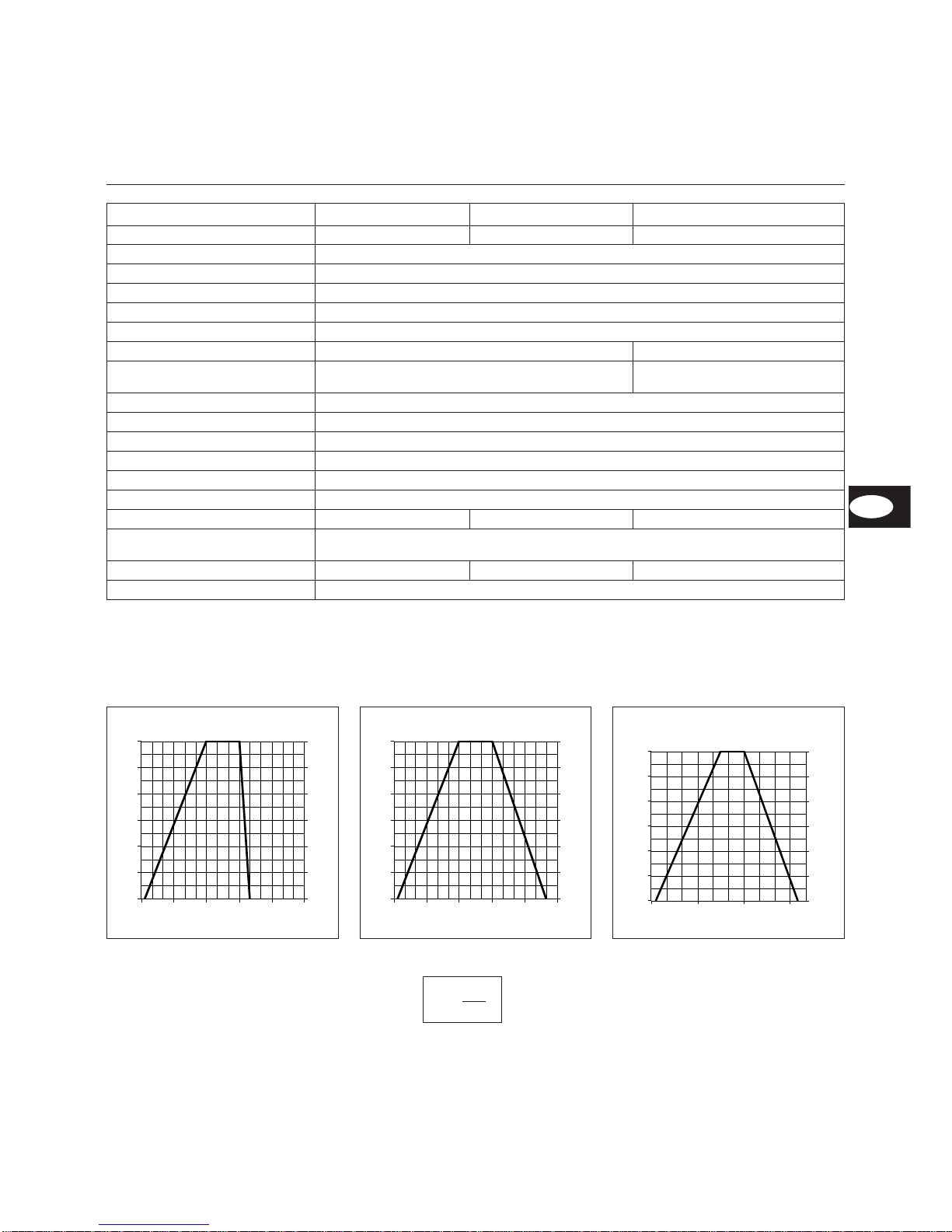
Power graphs
Power graphs are expressed as burner
power relative to furnace pressure.
They correspond to the maximum EN
676-compliant values, as measured at
the test combustion chamber.
The efficiency rating of the boiler
should be taken into account when
selecting a burner.
Page 24

07/2006 - Art. Nr. 13 018 114C
24
Overview
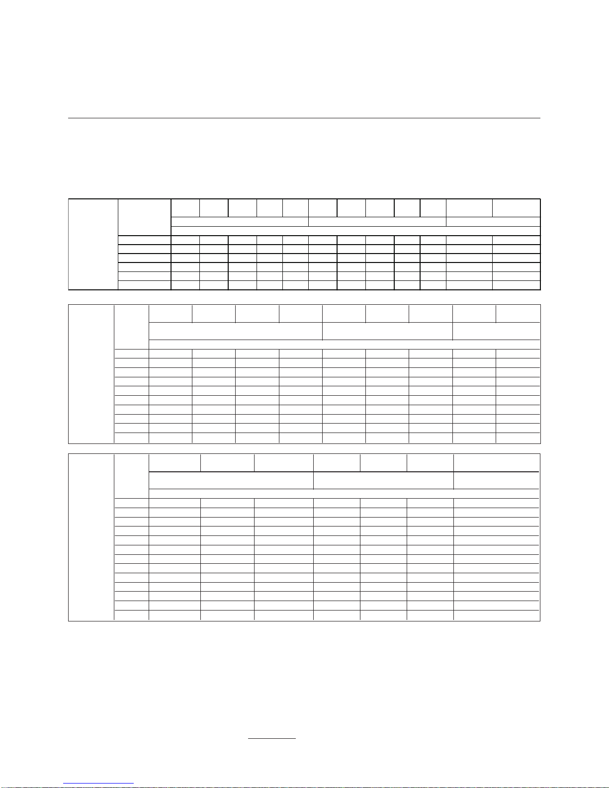
Selection of gas valve assembly
Selection of gas-valve assembly
·
The gas-pressure loss indicated in
the table is to be added to the
furnace pressure reading (in mbar).
·
The gas-flow pressure determined is
to be maintained at the inlet of the
gas-valve assembly. When
determining the gas-flow pressure
required at the transfer point,
remember to take into account the
resistance of the burner feed-conduit
and its fittings (ball valve, TAS,
additional filter or meter).
·
The operating point of the
installation must be inside the typical
authorized graph for the burner.
Example G 06.2100 DUO PLUS:
·
Specifications:
–
Type of gas supply: Natural gas E
–
Required burner power: 1600 kW
–
Furnace pressure at rated boiler load: 3 mbar
–
Gas flow pressure at supply station at rated boiler load : 30 mbar
–
Pressure loss in gas pipe at rated boiler load : 1 mbar
·
Selected gas valve assembly: VGD40
·
Testing of selection:
–
Gas pressure loss (from table): 25 mbar
–
Furnace pressure: 3 mbar
–
Pressure loss in gas pipe : 1 mbar
–
Total 29 mbar
–
Given: Gas flow pressure at supply station 30 mbar > 29 mbar ð Selection VGD40 correct.
G 06.2100
DUO-PLUS
Burner
power
(kW)
MBVEF
420
VGD20
Rp2
VGD40
DN65
MBVEF
420
VGD20
Rp2
VGD40
DN65
MBVEF
420
Natural gas E Hi = 10,365 kWh/m
3
Natural gas LL Hi = 8,83 kWh/m
3
Propane gas
Hi=25,89kWh/m³
Gas pressure loss (from entry of gas valve assembly)
1100 23 17 15 33 25 15 15
1150 25 18 15 36 27 15 15
1200 27 20 15 40 29 17 15
1250 30 22 15 43 32 18 15
1300 32 23 17 47 34 20 15
1400 37 27 19 54 40 23 15
1500 43 31 22 62 46 26 15
1600 49 35 25 71 52 30 17
1700 55 40 28 80 59 33 20
1800 62 45 32 89 66 37 22
1900 69 50 35 100 74 42 25
2000 76 55 39 - 82 46 27
2100 84 61 43 - 90 51 30
G 06.1600
DUO-PLUS
Burner
power
(kW)
MBVEF
412
MBVEF
420
VGD20
Rp2
VGD40
DN65
MBVEF
420
VGD20
Rp2
VGD40
DN65
MBVEF
412
MBVEF
420
Natural gas E Hi = 10,365 kWh/m
3
Natural gas LL Hi = 8,83 kWh/m
3
Propane gas
Hi=25,89kWh/m³
Gas pressure loss (from entry of gas valve assembly)
800 18 15 15 15 21 15 15 15 15
900 23 18 15 15 27 19 15 17 15
950 26 20 15 15 30 21 16 19 15
1000 29 22 16 15 33 23 17 21 15
1100 35 27 19 15 40 28 21 25 15
1200 41 32 23 17 48 33 25 30 15
1300 - 37 26 20 56 39 29 - 17
1400 - 43 31 23 65 45 34 - 20
1500 - 50 35 26 74 52 39 - 23
1600 - 57 40 30 85 59 44 - 26
MBVEF
412
MBVEF
420
MBVEF
425
VGD20
Rp2
VGD40
DN65
MBVEF
412
MBVEF
420
MBVEF
425
VGD20
Rp2
VGD40
DN65
MBVEF
412
MBVEF
420
800 18 15 15 15 15 41 21 15 15 15 15 15
900 23 18 15 15 15 52 27 16 19 15 17 15
950 26 20 17 15 15 58 30 17 21 16 19 15
1000 29 22 19 16 15 64 33 19 23 17 21 15
1100 35 27 23 19 15 78 40 23 28 21 25 15
1200 41 32 27 23 17 93 48 28 33 25 30 15
Propane gas Hi=25.89kWh/m³
Burner power
(kW)
G06.1200
DUO P LUS
Natural gas LL Hi = 8.83 kWh/m
3
Natural gas E Hi = 10.365 kWh/m
3
Gas press ure los s (from entry of gas val ve assem bly)
Page 25

25
07/2006 - Art. Nr. 13 018 114C
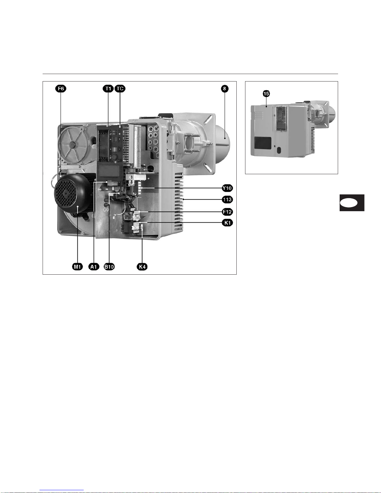
Overview
Burner description
A1 Control unit
B10 Ionisation bridge
F6 Air pressure switch
F12 Contactor thermal relay
K1 Ventilation motor contactor
K4 Relays
M1 Burner motor
T1 Ignition transformer (hidden)
TC Control panel
Y10 Servomotor of flap
8 Blast tube
15 Burner cover
113 Air box
EN
Page 26

07/2006 - Art. Nr. 13 018 114C
26
E
E
H
D
F
H
D
F
KL
KM
KN
KL
KM
KN
Distances
Maintain a clear distance of at least
0.6m to each side of the burner to allow
for maintenance operations.
Gas valve assembly
May be assembled from left or right.
Overview
Space requirements and dimensions
G 06.1200/1600/2100 DUO PLUS
with gas valve assembly MBVEF 412 and MBVEF 420
DEFH
MBVEF 412 186 590 107 Rp2
MBVEF 420 — 690 — —
Page 27

27
07/2006 - Art. Nr. 13 018 114C
DE
F
F
D
E
G
H
H
KL
KM
KN
KL
KM
KN
Overview
Space requirements and dimensions
G 06.1200/1600/2100 DUO PLUS
with gas valve assembly VGD20 - Rp2 and VGD40 - DN65
Distances
Maintain a clear distance of at least
0.6m to each side of the burner to allow
for maintenance operations.
Gas valve assembly
May be assembled from left or right.
DEFGH
VGD20 Rp2 186 292 734 344 Rp2
VGD40 DN65 290 292 740 365 DN65
EN
Page 28

07/2006 - Art. Nr. 13 018 114C
28
Function
Compact valve assembly MBVEF
1 Electrical connection for gas
pressure switch (DIN 43650)
2 Electrical connection for magnetic
valves (DIN 43650)
3 Gas pressure switch
4 Input flange
5 Pressure measuring nipple R1/8,
ahead of filter (both sides)
6 Filter (under cover)
7 Type plate
8 Connection for air pressure pipe
pL R1/8
9 Setting screw for V ratio
10 Pressure measuring nipple pe,
ahead of valve 1, both sides
11 Gas pressure measuring nipple
M4 after valve 2
12 Setting screw for zero value N
13 Connection for furnace pressure
take-off pipe pF,R1/8
14 Connection for gas pressure
take-off pipe pG,R1/8
15 Output flange
16 Pressure measuring nipple pa
after valve 1, both sides
17 V1 and V2 valve operation
indicator
18 Pressure release pipes
The MBVEF compact gas valve
assembly is a combination of filter,
gas / air controller, valves and pressure
switches:
–
fine 0.8mm mesh filter
–
GWA5 pressure switch
–
servo pressure controller unit with
adjustable V ratio, correction of zero
value N and furnace pressure
connection
– V1 and V2 fast-opening and closing
magnetic valves
Input pressure pe: 20-100 mbar
Voltage, frequency: 230V, 50-60Hz
NV
Gas-pressure switch adjustment
·
Remove transparent cover.
Adjustment is carried out by turning
the adjustment screw with circular
scale and index x.
·
Adjust provisionally to minimum
setting.
Burner G 06.1600/2100 DUO PLUS
Gas: pressure(s)
VEF
412 420
E-Gas: 20, 25
LL-Gas: 20, 25
V
1,25
N
0
E-Gas : 100
LL-Gas: 100
V
1,25
N
0
F-Gas : 37
V
1,25
N
0
F-Gas : 50
V
1,25
N
0
Bold print: factory supply
Page 29

29
07/2006 - Art. Nr. 13 018 114C
1 Electrical connection for gas
pressure switch (DIN 43650)
2 Electrical connection for magnetic
valves (DIN 43650)
3 Gas pressure switch
4 Input flange
5 Pressure measuring nipple R1/8,
ahead of filter (both sides)
6 Filter (under cover)
7 Type plate
8 Connection for air pressure pipe
pL R1/8
9 Setting screw for V ratio
12 Setting screw for zero value N
13 Connection for furnace pressure
take-off pipe pF,R1/8
14 Connection for gas pressure
take-off pipe pG,R1/8
15 Output flange
16 Pressure release pipes
pBr (pG)= Gas pressure release
pF = Furnacepressure release
pL = Airpressure release
SKP controller with VGD valve ensures
a constant ratio between gas flow and
air flow thanks to an adjustable ratio
D = pressure adjusting screw
(air excess)
R = pressure adjusting screw
(Gas/air ratio)
Function
VGD gas valve assembly with SKP controller
Gas-pressure switch adjustment
·
Remove transparent cover.
Adjustment is carried out by turning
the adjustment screw with circular
scale and index x.
·
Adjust provisionally to minimum
setting.
Burner G 06.1200 DUO PLUS
Gas:
pressure(s)
VGD
Rp2
VGD
DN65
E-Gas: 20, 25
LL-Gas: 20, 25
(Schr. R) 1,4 1,3
(Schr. D) 22
Burner G 06.1600/2100 DUO PLUS
Gas:
pressure(s)
VGD
Rp2
VGD
DN65
E-Gas: 20, 25
LL-Gas: 20, 25
(Schr. R) 1,3
(Schr. D) 2
Bold print: factory supply
Gas valve
opening display
EN
Adjustment level
of D
Adjustment
level of “R” ratio
Page 30

07/2006 - Art. Nr. 13 018 114C
30
Function
TC Control panel
TC Control panel
All control components are visible from
the outside. A transparent detachable
lid clipped on the cover provides access
to the different controls and control
components for settings and burner
operation.
The control panel also includes a
measuring bridge for the flame signal,
as well as a protective fuse.
To detach the lid, press slightly to one
side, or on both sides, and remove
simultaneously.
To replace the lid, place the 2 clips in
front of their corresponding orifices
and press.
Optional:
–
hour meter (connection cable
already in place)
–
RWF 40 three point stage controller
in the standard position.
Functions
A2 Standard 48x48 or 48x96 mm
positions for the installation of a
power controller (optional)
A4.1 Position with clips for the display
B10 Mesuring bridge [µA DC] for cell
current, placed next to the motor
contactor
F10 Fuse
S1 Main switch
0 OFF
1 ON, green light
H10 lit on the switch
S2 Selection of power regulation
K Manual mode
Auto Automatic local mode
S3 Operates in connection with
switches
S28J - S2K
+/- power increase/power
decrease
S5 Remote unit switch:
- fault display, red H6 light lit
- reset push-button
S28 Choice of control venue
J Local Mode
H Remote control mode
(optional)
m
Caution:
The main switch on the control panel
only sets off control voltage. Prior to all
action in the section of the burner
switch, turn the burner off, including the
triphase burner motor connection.
Page 31

31
07/2006 - Art. Nr. 13 018 114C
Function
Control unit SG 513
Operating diagram
Required Input signals
Output signals
EN
Press button
“R”
for ...
… leads to …
… less than 9
seconds...
Unblocking or
blocking of the
control unit
… between 9
and 13
seconds...
Delete the
statistics of the
control unit
… more than 13
seconds...
No effect
on control unit
The SG 513 gas control unit controls and monitors
the forced-draught burner. The microprocessorcontrolled program sequence ensures the
maximum consistency of the time periods involved,
regardless of fluctuations in the power-supply
voltage or ambient temperature. The design of the
automatic unit protects it from the effects of
brownouts. Whenever the supply voltage drops
below its rated minimum level, the control unitshuts
down - even if no malfunction signal hasbeen
emitted. The control unit switches itself back on
again once the voltage has returned to normal
levels.
Information system
The built-in visual information system keepsyou
up-to-date regarding the causes of any safety
shutdown. The most recent cause of a malfunction
is logged, and the information can be reconstructed
on startup of the system - even if there hasbeen a
power failure in the meantime. In the eventof a
malfunction occurring, the LED indicator in the
"Reset" button (R) lights up and stays permanently
lit until the fault has been acknowledged (i.e. until
the error has been cleared or the control unitfault
has been dealt with).
The light pauses every ten seconds to emit a
blink-code designed to indicate the cause of the
malfunction. It is possible, using the display
program (available as an accessory), to obtain
further in-depth information on the system's
operating and malfunction procedures.
Locking and unlocking the system
The automatic unit can be locked (corresponding to
a malfunction) and unlocked (cleared) by pressing
the "Reset" button (R), provided the system is
connected to the power supply. If the buttonis
pressed during normal or startup mode, the device
goes into malfunction mode. If the button ispressed
with the system in malfunction mode, the automatic
unit is unblocked.
m
Always disconnect the power supply before
installing or removing the automatic unit. DO
NOT attempt to open the automatic unit, as
there are no user-serviceable parts inside.
Blink-code Cause of malfunction
I IIII
No flame signal at end of safety time.
II III
Unauthorised flame detected during the pre-ventilation/pre-ignition
time.
III II
Pressure switch: Contact fails to close within defined time period.
IIII I
Pressure switch: Contact opens at startup or during operation.
II III
Pressure switch switch not in rest position, e.g. due to fused
contact.
IIII I
Flame goes out during operation.
II III — IIIII
Manual safety shutdown (refer also to locking procedure).
Code
I
I
—
Note
Short light signal
Long light signal
Pause
1 Activation of control unit, motor and SM
2 Testing of air pressure
3 End of pre-ventilation
4 Activation of transformer and end of
pre-ventilation phase
5 Activation of gas valve
6 Flame check
7 Activation of SM and gas valve, followed by burner
operation
0 Regulator shutdown - burner stopped
10 Malfunction mode
tlw Waiting period of pressure switch
tlk Opening time of servomotor and discharge of
pre-ventilation
tr Shutting time of servomotor
tvz Pre-ignition time
ts Safetyvalve
tv2 Minimum time between fuel valve 1 and 2
Temper.controller pressure switch Burner motor Gas valve Regulation Ignition transf. Flame monitor Servomotor (SM) fault Unblocking
Page 32

07/2006 - Art. Nr. 13 018 114C
32
Installation
Burner assembly
Burner installation depth and
brickwork
On heat generators without a cooled
front wall, unless the boiler
manufacturer indicates otherwise,
brickwork 5 as shown in the illustration
is required. The brickwork must not
protrude beyond the leading edge of
the flame tube, and should have a
minimum conical angle of 60°. The
space between the brickwork and
burner tube should be filled with an
elastic, non-flammable insulation
material 6. On boilers with reverse
firing, minimum insertion depth A of the
burner tube should be observed as per
the instructions of the boiler
manufacturer.
5
4
6
Ø a (mm) Ø b (mm) c d
250
300 to 400
M12 45°
Fitting the burner head
·
Prepare the burner fixing plate/boiler
door as per the drawing.
·
Establish the internal diameter a at
Ø 250 mm.
·
To secure the burner head flange, 4
M12 drillings (drilling diameter 300 400mm) are required as per the
drawing.
·
Screw the M12 stay bolts into the
burner fixing plate/boiler door and
apply the insulation material. With a
slot diameter < 270 mm, elongated
slots should be cut to the required
dimensions.
·
Secure the burner head using 4
M12 hexagon nuts.
·
Fill in the space between door
insulation and the burner blast tube
with fire-resistant material.
Caution:
the entry piping to the pF furnace
pressure must not be clogged.
Assembly of burner body
If the burner body is hung under burner
head axis, proceed as follows.
·
Attach burner body to the combustion
head (facing the gas connection)
using the fixed spindle F.
· Raise the combustion head and
tighten with the side screw C
(counter-nut M10 and Inbus screw).
· Connect the two ignition cables and
the ionisation cable.
· Close the burner with spindle E.
· Tighten the safety screw D.
· Where required, the housing can be
fitted over the burner head axis.
Other burner housing positions are not
possible.
Page 33

33
07/2006 - Art. Nr. 13 018 114C
Installation
Assembly of the gas valve assembly
Leak controller VPS 504 S01
Installation of valve assembly
SKP70/MBVEF
·
Check the correct position of the
O-ring B in the gas connecting
flange C.
·
Attach the gas valve assembly with
M10 nuts, to ensure that the SKP
controller or the magnetic coils from
MBVEF are imperatively placed
perpendicular to the gas valve
assembly.
·
Assembly the pressure pipes
supplied and marked pF, pL and pG
for gas connections to the left or
right.
·
For SKP75, assemble the back-up
solenoid valve provided (kit) with the
coil towards the top, the gas filter
(kit) horizontally, and with the lid up
(2 connectors).
·
Pay attention to the direction of flow.
·
Assemble a thermally-triggered valve
and a ball valve (installation side)
upstream from the gas valve
assembly.
Connection of pressure tubes
·
Remove the two pF and pL caps on
the intermediate tube.
·
Seal both connection tubes linked
with an appropriate product,
assemble the two tubes to the pF
and pL pressure tubes.
· Establish links between the valve
and the intermediate tube for a gas
valve assembly located to the right
with the pF and pL pipes, or, for a
gas valve assembly located to the
left, with the pF and pL pipes
marked “left”.
· Subsequently check tightness.
Assembly of the leak controller VPS
504 S01 on MBVEF/VGD40:
·
Remove the two pa and pe screws
on the MBVEF valve, screws 1 and
2 on the VGD4 0 valve.
·
Ensure the presence of two O’Ring
seals on the leak controller.
·
Attach the VPS504 with the four
self-tapping screws provided.
·
Establish the electrical connection
using the 7p plug.
·
Check tightness.
Assembly of the leak controller VPS
504 S01 on VGD20:
·
Remove screws 3 and 4.
·
Tighten the nipples.
·
Install the connection adapter and
the pipework.
·
Attach the VPS504 and the
connection adapter with the four
self-tapping screws provided.
·
Ensure the presence of two O’Ring
seals on the leak controller.
·
Establish the electrical connection
using the 7p plug.
·
Check tightness.
1
2
3 4
EN
Page 34

07/2006 - Art. Nr. 13 018 114C
34
4
Installation
Check combustion head
Secondary air
Combustion head setting for natural gas/propane
Check combustion head
·
Unscrew the safety screw D (see
page 32).
·
Remove the mobile spindle E.
·
Open the burner body.
·
Unplug the ignition cables and the
ionisation cable.
·
Unscrew the four screws in the
setting plate by 2 rotations.
·
Unscrew the fastening screw C.
·
Remove the combustion head.
·
Check the settings of the ignition
electrodes and of ionisation probe /
turbulator and re-adjust.
·
When re-assembling, proceed in
reverse order.
·
Check condition and position of the
J1 gasket.
·
Check tightness.
Secondary air
Secondary air is the air flow between
the blast tube and the turbulator.
The turbulator position (dimension Y)
may be read on the graduated scale on
the RTC setting plate. Position 50
corresponds to the maximum quantity
of secondary air and 0 to the minimum
quantity. Upon delivery of the burner,
dimension Y is set at 30mm or 35mm.
Depending on burner power and the
installation conditions, adjustment may
be necessary to optimize ignition quality
and combustion values.
Adjustment
Adjustment may occur during burner
operations. Basic setting values,
depending on burner capacity, are
indicated page 36.
· Remove the 2 screws 2 (diagram).
· Move the plate in the desired
direction.
· Rescrew the 2 screws 2.
For a change in dimension Y:
the level of CO
2
is either increased or
decreased.
Recommended settings for natural
gas
On the gas diffuser marked A, keep 5
slots open towards the exterior and 1
towards the interior by sliding the
shutter/diffuser E.
Attaching the turbulator using 6 M5X6
perforated screws F.
On the gas diffusers marked B, keep
5 slots open towards the exterior and
0 towards the interior by sliding the
shutters/diffusers E.
Recommended settings for propane
gas
On the gas diffusers marked A, keep 3
slots open towards the exterior and 1
towards the interior by sliding the
shutter/diffuser E.
Attaching the turbulator using 6 M5X6
non-perforated screws F.
On the gas diffusers marked B, keep
3 slots open towards the exterior and
0 towards the interior by sliding the
shutters/diffusers E.
Ionisation probe / Ignition electrode
Page 35

35
07/2006 - Art. Nr. 13 018 114C
Installation
Gas supply
Electrical supply
Pre-startup check
All electrical installation and
connection work MUST be carried
out by a suitably qualified service
engineer. VDE and EVU (RGIE-AREI
for Belgium) rules and regulations
must be observed when doing so.
Electrical connection
· Check to ensure that the power
supply is as specified (230 V, 50 Hz)
Burner fuse rating: 10A
Electrical plug connection
The electrical plug-and-socket
connection, burner and heat generator
(boiler) are linked via one 7P. and one
4P. plug-and-socket connection.
Connect gas train thanks to the
delivered connectors.
Burner motor connection
The burner is delivered for a power
supply of 400V - 50Hz of triphase
current with neutral and earth.
Pass the burner motor connection
cable in the flange, and connect to the
terminal.
Check the direction of rotation of the
ventilation motor (see arrow on burner
body) manually with the burner
contactor.
Pre-startup check
The following tests and checks must be
carried out before the burner is used for
the first time.
–
Operating specifications of the boiler
manufacturer
–
Adjustment of:
–
temperature controller
–
pressure controller
–
limiting device
–
safety switch
–
gas input pressure min. 20mbar flow
pressure
–
correct sealing of gas-bearing
elements
–
purging of fuel-bearing conduits
–
unobstructed exhaust conduits,
sufficient supply of fresh air
–
Direction of rotation of the ventilation
motor (see arrow on the body of the
burner).
Testing of burner program
sequence before releasing gas for
first time
·
Close ball valve upstream of gas
valve assembly.
·
If gas pressure upstream of valve
assembly is insufficient, bypass the
gas pressure switch (terminal 2 and
3) if necessary, shutting down the
power supply to the burner.
·
Activate the boiler to start up the
burner, and check the program
sequence.
·
The blower runs with a delay that
depends on the adjustment setting
of the control unit.
·
Pre-ventilation time (54s)
·
Pre-ignition time (3s)
·
Open solenoid valves
·
Safety period (3s)
·
Fault shutdown after expire of safety
period, with blocking of control unit
(fault indicator lamp lights up)
·
Shut off power to burner by
disconnecting electrical supply, and
remove any bypass connection fitted
to the gas pressure switch.
·
Reconnect electrical power supply.
·
Press button R to reset control unit.
General regulations applying to gas
supply
·
The gas-valve assembly MUST be
connected to the gas supply network
by an authorised service engineer.
·
The cross-section of the gas conduit
should be of a size designed to
guarantee that the gas flow pressure
does not drop below the specified
level.
The act of startup places the system
under the joint responsibility of the user
and the fitter engaged to carry out
installation, or the latter's
corresponding legal representative.
Only the authorised fitter can guarantee
that the system conforms to relevant
standards and regulations.
The fitter should be in possession of
the corresponding official permit, and
should carry out the corresponding leak
tests and purging of the system.
EN
Page 36

07/2006 - Art. Nr. 13 018 114C
36
Startup
Burner adjustment data
Airflow control
Adjusting the gas pressure switch
·
Remove transparent cover.
·
Settings require the use of an
adjustment disk with a graduated
circular dial and an index.
·
Provisionally adjust air-pressure
switch to minimum setting.
Adjusting the air-pressure switch
·
Remove transparent cover.
·
Settings require the use of an
adjustment disk with a graduated
circular dial and an index.
·
Provisionally adjust air-pressure
switch to minimum setting.
Type
Burner power
kW
Dimension
Y
mm
Position of the flap (°)
Ignition load
Cam III
Full load
Cam I
G 06.1200 DUO-PLUS
700 25 10 35
900 30 10 45
1100 35 10 50
1200 40 10 60
G 06.1600 DUO-PLUS
1100 35 10 50
1300 45 10 80
1600 50 10 90
G 06.2100 DUO-PLUS
1150 25 10 55
1400 30 10 65
1700 35 10 80
1900 50 10 85
2100 50 10 90
The above adjustment data correspond to the default settings. Pre-delivery adjustment settings appear within a black
rectangle. These settings allow the burner to be run in normal operation, but always carry out a careful check of adjustment
settings, as individual plant conditions may require certain corrections.
Airflow control in the burner head
has an effect on the air quantity, as well
as on the mixing zone and the air
pressure in the burner tube.
·
Adjust dimension Y corresponding to
table of settings.
For this:
·
Unscrew the screw 2.
·
Slide the RTC plate:
–
back = more air
–
forward = less air
m
Do not touch screw 1.
The combustion air is regulated at two
points:
·
On the pressure side by means of
the opening gap between the
turbulator and burner tube.
·
On the suction side by means of the
air flap actuated by servomotor Y10.
4
Page 37

37
07/2006 - Art. Nr. 13 018 114C
Startup
Airflow control
Airflow regulation using an air flap.
This is actuated by the servomotor Y10.
The position of the air flap is
determined by adjusting cams I - IV.
1 Index of cam settings
2 Four adjustable cams
3 Key to cam settings
4 Graduated disk; gives the
position of the flap
5 Cap for the flap release of the
servomotor
6 Connections terminal
A Graduated sector (0° - 90°)
gives the servomotor position
B Connection between the flap
and the servomotor
C Index of positions of the flap.
Control of fuel air settings
The position of the flap may be read on
the graduated sector A.
If the burner is assembled in the
opposite sense, the position of the flap
may be read on the graduated sector 4.
Cam function
Cam Function
I Full load
II Air shut-off
III Ignition load
IV Non-adjustable, depends on cam
V
V Minimum regulation load
Operations
A-B Preventilation
B-C Power regulation
C-D Regulation stop
Adjustment
·
Pre-set cams manually or with the
delivered key, depending on the
desired burner power and the values
indicated in the settings table.
·
If no difference in settings between
the ignition load and part-load is
necessary, adjust cam V and cam III
to the same value (to the right of the
image). Should a higher part-load
setting to the ignition load be
required, adjust cam V to a value
higher than cam III. After an initial
high setting for the burner, cam V
will begin to restrict the part-load (to
the left of the image).
V > III V = III
EN
Page 38

07/2006 - Art. Nr. 13 018 114C
38
Adjusting the burner
·
Open the gas ball valve.
·
Set the gas and air pressure
switches to the minimum values.
·
Connect a micro ammeter (0-100µA)
in place of the measuring bridge
(test polarity).
·
Press on the rocker switch S1/H10.1
- S29J-S2K .
·
Switch on the boiler controller.
·
Re-set the control unit.
·
Check the combustion values (CO,
CO
2
) after the flame has appeared.
·
Read the ionisation current
(reference value min. 8µA).
·
Read the gas flow on the gas meter.
·
Increase power on full load by
pressing on + on the push-button
switch S3
·
Check combustion values. Re-adjust
the gas/air ratio depending on the
value measured:
–
on the SKP, adjust the adjusting
screw R. For this, remove the upper
cover. More CO
2
in direction +. Less
CO
2
in direction -. (see upper
symbol section SKP75 page 29)
–
adjust screw V on the valve MB
VEF. More CO
2
in direction of
higher scale values. Less CO
2
in the
direction of lower scale values (see
page 28).
·
To reach the desired yield, respect
CO
2
and combustion values as
recommended by the boiler
manufacturer.
·
Read the measurement of the
ionisation current (minimum
recommended value: 8µA).
·
Read the gas flow on the gas meter.
·
Switch the burner to part-load and
check combustion values.
Depending on measures, adjust
screw D on the controller SKP or
adjust screw N on the controller MB
VEF.
·
Determine the desired part-load with
the button S3. For this, depending
on requirements, adjust cam V on
the flap servomotor.
·
Once again check combustion
values, and, depending on
measures, re-adjust gas/air ratios.
·
Switch the burner to full load and
check combustion values.
· If the measures of screw D have
changed on the controller SKP, or
screw N on the valve MB VEF,
re-adjust the ratio R on the
controller SKP or ratio V on valve
MB VEF, as desired.
· If combustion head (dimension Y)
settings require modification,
adjustments must begin at zero.
If combustion values are correct,
continue as follows for the part-load
and full load:
·
Adjust the gas flow by adjusting
cams V and I on the servomotor.
·
Check the gas flow on the gas
meter.
Ignition load setting
The ignition load must be set with cam
III to ensure safe burner startup.
The ignition load must be set in order to
prevent condensation in the boiler
Startup
Burner adjustment
Gas pressure switch / air pressure switch adjustment
Checking for correct functioning
Adjusting the gas pressure switch
·
To adjust the shutoff pressure: Remove
cover of the gas pressure switch.
·
Activate burner and adjust gas
pressure upstream of valve assembly
by turning the ball valve until the
desired shutoff pressure is set.
·
Turn the dial clockwise until the gas
pressure switch shuts down the burner.
Adjusting the air pressure switch
·
Set burner at low-load.
·
Turn the dial clockwise until the air
pressure switch shuts down the
burner.
·
Set air pressure switch at 70% of
shutdown value.
Checking for correct functioning
The flame-monitor should be checked
for safe and reliable functioning before
initial startup, during regular servicing
and after any extended shutdown
period.
–
Startup attempt with closed gas
valve: Note that the control unit
MUST go into malfunction mode at
the end of the safety period.
–
Normal startup - if burner is in
operation, shut gas valve: after the
flame goes out, the control unit must
go into fault mode!
–
Normal startup ; interrupt
air-monitoring contact during
preliminary ventilation or operation:
Control unit should go into fault
mode IMMEDIATELY.
–
Bypass air-pressure switch before
startup: Burner activates for approx.
2-3 sec., before carrying out fault
shutdown. After 10 sec., this brief
malfunction is automatically reset by
the control unit, and a second
startup attempt ensues (motor
activates for 2-3 sec.). If the LW
contact is still closed (e.g. due to
fused contact) resulting in genuine
emergency shutdown.
However, if the LW contact has
opened within these 10 sec. (e.g.
due to decelerating motor), normal
operation ensues.
Page 39

39
07/2006 - Art. Nr. 13 018 114C
Servicing
Maintenance
All boiler and burner servicing work
should be carried out by an
appropriately trained heating service
specialist. It is recommended to enter
into a maintenance contract in order
to ensure that servicing is carried out
at the intervals prescribed.
m
·
Shut down the power supply
BEFORE carrying out servicing or
cleaning work of any kind.
·
Close ball valve.
·
Use only original spare parts.
Control combustion temperature
·
Regularly check combustion
temperature.
·
Clean the boiler when the
combustion temperature exceeds the
startup value by more than 30°K.
·
To simplify checks, you may use a
combustion temperature display.
A1 Control and safety unit
B10 Ionisation bridge
F6 Air pressure switch
F12 Contactor thermal relay
K1 Ventilation motor contactor
K4 Relays
M1 Burner motor
T1 Ignition transformer (hidden)
TC Control panel
Y10 Servomotor of flap
8 Blast tube
113 Air box
Control of ignition electrodes and
the combustion head
·
Unscrew the safety screw D (see
page32).
·
Remove the mobile spindle E.
·
Open the burner body.
·
Unplug the ignition cable and the
ionisation cable.
·
Unscrew the four screws in the
setting plate by 2 rotations.
·
Unscrew the fastening screw C.
·
Remove the combustion head
·
Check the settings of the ignition
electrodes/turbulator and readjust.
·
When re-assembling, proceed in
reverse order.
·
Check the condition and position of
the J1 gasket.
·
Check tightness.
Cleaning the air fan
·
Turn the motor off by unplugging the
power supply.
·
Unscrew the 7 screws of the motor
base plate.
·
Remove the motor base plate
carefully and put it aside without
damaging the air pressure switch
tube.
·
“Dry” clean air pressure hoses.
·
Do not use liquids under pressure.
·
Unscrew the 4 fixation screws from
air recycling.
·
Clean the hydraulic circuit and the
air fan.
·
Re-assemble.
EN
Page 40

07/2006 - Art. Nr. 13 018 114C
40
Servicing
Maintenance
Remove the flame tube.
To carry out this procedure, the furnace
door must be opened or the burner
removed.
–
Variant 1 – access via the furnace
door.
·
Remove the mixer control/ignition
device.
·
Loosen the 3 fixing screws on the
flame tube support by 1 to 2 turns.
Precautions: The screws are
threaded to the left (Inbus 3).
·
Remove the flame tube lever. To do
this, loosen fixing screw M4 in the
flame tube.
·
Remove the flame tube, check,
clean, and where necessary, replace
if a deformity is found.
·
The space between the flame tube
and the door insulation should be
fitted with flame-proof material.
·
Refit the flame tube in the reverse
sequence.
–
Variante 2 - Remove the burner
· Remove the mixer control/ignition
device.
· Loosen the electrical connections.
· Remove the gas valve assembly.
· Unscrew the gas connection (4 M10
nuts).
· Loosen the burner housing (4 M10
screws) and remove. Do not
damage electrical cables.
· Unscrew the burner head and then
proceed as for variant 1.
·
Refit in the reverse sequence.
Valves
The gas valves require no special
servicing.
Gas valves cannot be repaired.
Defective valves must be replaced by a
qualified service engineer, who should
then carry out tests to check for leaks,
and determine correct functioning and
combustion.
Replace the gas filter
The filter component must be controlled
annually and replaced if clogged.
·
Unscrew fixation screws in the lid on
the filter, prefilter or Multibloc.
·
Remove the filter component taking
care to not get dirt in the filter.
·
Install a new filter.
·
Re-assemble the lid with its screws.
·
Open the ball valve: check tightness.
Cleaning the hood
·
Clean the cover with water and a
cleaning product.
·
Do not use chlorine-based or
abrasive cleaning products.
m
Precautions
After each intervention, check the
combustion performance under real
operating conditions (doors shut,
cover fitted etc.).
· Note down the results in the
corresponding report forms.
Page 41

41
07/2006 - Art. Nr. 13 018 114C
Servicing
Troubleshooting
Fault diagnosis and repair
Before carrying out fault diagnosis,
check that the basic requirements for
correct operation are being fulfilled:
1. Is the system connected to the
power supply?
2. Is the system connected to the
gas supply?
3. Is the gas ball valve open ?
4. Are all regulating and safety
devices (boiler thermostat, low
water level detector, end-limit
switches, etc.) correctly adjusted?
If the malfunction persists:
·
Note any blink-codes emitted by the
control unit, and check their
meaning with the following table.
Use the MDE
®
ELCOSCOPE readout
program (available as an optional
accessory) to obtain further in-depth
information on the control unit's
operating and malfunction procedures.
DO NOT attempt to repair safety
components. Replace them with
original parts bearing the same order
number.
m
Use ORIGINAL spares only.
Note:
After each intervention:
·
Check combustion performance and
examine the individual conduits for
signs of leaks under real operating
conditions (doors shut, hood fitted,
etc.).
·
Note down the results in the
corresponding report forms.
EN
Malfunction Cause Remedy
Burner fails to start after thermostatsignal.
No fault indication on control unit.
Brownout or power cut.
Fault in control unit.
Check for cause of reduction or failure of
power supply.
Replace control unit.
Burner fails to start.
Gas pressure normal.
Air-pressure switch in working order.
No request for heat.
Insufficient gas pressure
Gas pressure switch maladjusted or defective.
Air-pressure switch not in home position.
Thermostat defective or maladjusted.
Check gas conduits.
Clean filter.
Check gas pressure switch or replace
compact gas-fired unit.
Readjust or replace air-pressure switch.
Readjust or replace thermostat.
Burner activates briefly at startup,
then shuts down and emits following signal:
II III - IIIII
Control unit has been shut down intentionally. Reset control unit.
Burner fails to start.
II III
Air-pressure switch: not in home position
incorrectly adjusted
Fused contact
Readjust pressure-switch.
Replace pressure-switch.
Burner-blower starts up. Burner fails to start.
III II
Air-pressure switch: Contact fails to close. Examine pressure-switch and check wiring.
Readjust pressure-switch.
Burner shuts down during normal operation.
IIII I
Air-pressure switch: Contact opens at startup
or during continuous operation.
Readjust or replace pressure-switch.
Burner-blower starts up. Burner fails to start.
II III
Light scatter during pre-ventilation or
pre-ignition.
Replace valve.
Burner starts up, ignition sequence activates,
then stops
I IIII
No flame present at end of safety period.
Gas throughput rate incorrectly adjusted.
Fault in flame-monitoring circuit.
No ignition arc.
Electrode(s) shorted.
Ignition cable damaged or defective.
Ignition transformer defective.
Control unit.
Solenoid valves fail to open.
Valves jammed.
Regulate gas throughput rate.
Check general state and adjustment settings
of ionisation probe by connecting to earth
(ground).
Check general state and connections of
ionisation circuit (wiring and measuring
bridge).
Clean and adjust ignition electrode(s),
replacing as required.
Connect or replace ignition cable.
Replace transformer.
Replace control unit.
Check wiring between control unit and
external components.
Check coil, replacing as required.
Replace valve.
Burner shuts down during normal operation.
IIII I
Flame goes out during normal operation. Check circuit of ionisation probe.
Check control unit, replacing as required.
Page 42

07/2006 - Art. Nr. 13 018 114C
42
Page 43

43
07/2006 - Art. Nr. 13 018 114C
Ersatzteilliste
Spare parts list
Pièces de rechange
Wisselstukkenlijst
VECTRON G 06.1200 DUO-PLUS
VECTRON G 06.1600 DUO-PLUS
VECTRON G 06.2100 DUO-PLUS
Page 44

44 07/2006 - Art. Nr. 13 018 114C
Pos. Désignation Bezeichnung Omschrijving Description Art. Nr. Art. Nr. ELCO D
500 Tête de combustion Brennkopf BG Branderkop Mixing unit
G 06.1200/1600 DUO-PLUS
KN 13004600 13004600
KL 13004601 13004601
KM 13004602 13004602
G 06.2100 DUO-PLUS
KN 13004641 13004641
KL 13004642 13004642
KM 13004643 13004643
Désignation simplifiée Symboldarstellung Benaming vereenvoudigd Simplified designation
G 06.1200 DUO-PLUS = 1200 G 06.1200 DUO-PLUS = 1200 G 06.1200 DUO-PLUS = 1200 G 06.1200 DUO-PLUS = 1200
G 06.1600 DUO-PLUS = 1600 G 06.1600 DUO-PLUS = 1600 G 06.1600 DUO-PLUS = 1600 G 06.1600 DUO-PLUS = 1600
G 06.2100 DUO-PLUS = 2100 G 06.2100 DUO-PLUS = 2100 G 06.2100 DUO-PLUS = 2100 G 06.2100 DUO-PLUS = 2100
Page 45

4507/2006 - Art. Nr. 13 018 114C
Pos. Désignation Bezeichnung Omschrijving Description Art. Nr. Art. Nr. ELCO D
500.1 Coude gaz éq. Lanzengaskopf BG Sproeierlijn Lance gas head kpl.
KN 13010051 * 13010051 *
KL 13010052 * 13010052 *
KM 13010053 * 13010053 *
501 Déflecteur Stauscheibe Vlammenhaker Turbulator
1200/1600 Ø 168/50-8FD. +7Ø5 13009711 13009711 }
2100 Ø 155/50-8FD. +7Ø5 13009712 13009712 }
503 Embout Brennerrohr Branderbuis Blast tube
1200/1600 Ø 190/172/227
x 343 KN 13009713 13009713
x 543 KL 13009714 13009714
x 443 KM 13009715 13009715
2100 Ø 205/160/227
x 343 KN 13009716 13009716
x 543 KL 13009717 13009717
x 443 KM 13009718 13009718
504 Joint/façade chaudière Isolierflansch Dichting klingerit Flange klingerit 13009719 13009719
505.3 Vis embase M8x20/embout Schraube/Brennerrohr Vijs / branderbuis Screw M8x16/blast tube 13009723 13009723
505.4 Axes (fixe+mobile) Fuehr Bolzen Set Assen Axes 13009724 13009724
507 Bride/électrode Klemmfeder Flens/elektrode Electrode fix. plate 13009725 13009725
508 Electrode allu. (bloc blanc) Elektroden Block (weiß) Electrode onst. (blok wit) Electrode (white block) 13009726 13009726 }
508.1 Support électrode & sonde Halterung/Elektr.+ Fühler Elektrode- & sondevoet Electrode/Ioni.support 13010050 13010050
509 Câble allu./tête L.950 Zündkabel Ontstekingkabel/kop Ignition lead 13009727 13009727
509.1 Fiche ronde Ø6.4 Rundstecker Hülse Ø6,4 Ronde pin Ø6,4 Round plug Ø6,4 13010056 3333 261 906
510 Vis épaulée M4/électrode Schraube M4 / Elektrode Vijs épaulée Screw M4 /electrode 13010049 13010049
511 Sonde ionisation Ionisationsstab Ionisatiesonde Ionisation probe 13009626 13009626 }
511.1 Câble ionisation / tête de
combustion L.950
Ionisationskabel /Brennkopf L.
950
Ionisatiekabel /
verbrandingskop L 950
Ionisation cable/combustion
head L.950
13009728 13009728
511.2 Bride/sonde ionisation Klemmfeder/Ionisationsstab Ionisatie-/sondeflens Probe fixing plate 13010054 13010054
512 Obturateur/diffuseur Schiebehülsen Set Afsluiter/verdeler Gas ring/diffusor 13010046 13010046
513 Diffuseurs complets Gasdüsen BG Volledige verdelers Diffusor kpl. 13010047 13010047
513.2 Kit vis gaz naturel Erdgas Schraubenset Kit schroeven aardgas Natural gas screws set 13010048 13010048
513.3 Kit vis gaz propane Flüssiggas Schraubenset Kit schroeven propaangas Propane gas screws set 13007041 13007041
515 Joint torique/coude gaz O’Ring/Lanzengaskopf Afdichting/gasbochtstuk O’Ring / lance gas head 13009731 13009731 |
* Livraison avec délai Keine Lagerware, wird b. Bedarf
bestellt
Levering met termijn Delivery with delay
Page 46

46 07/2006 - Art. Nr. 13 018 114C
Page 47

4707/2006 - Art. Nr. 13 018 114C
Pos. Désignation Bezeichnung Omschrijving Description Art. Nr. Art. Nr. ELCO D
550 Corps Gebläseteil BG Behuizing Casing
G 06.1200/1600 DUO-PLUS 13 006 887 13 006 887
G 06.2100 DUO-PLUS 13 006 888 13 006 888
551 Boîte à air éq. Luftkasten BG Luchtkast Air box cpl. 13 009 735 * 13 009 735 *
552 Joint boîte à air/carter Dichtband Luftk./BG Dichting luchtkast Seal air damper/casing 13 009 640 13 009 640
553 Isolation/boîte à air Isolierung/Luftkasten Isolatie/luchtkast Insulation air damper cover 13 009 641 13 009 641
554 Couvercle/boîte à air Deckel/Luftkasten Deksel/luchtkast Air damper cover 13 009 642 13 009 642
555 Volet d'air Luftklappe kpl. Luchtklep Air flap cpl. 13 014 117 13 014 117
557 Ressort plat/ volet d'air Feder/Luftklappe Veer/luchtklep Flat spring/flap 13 011 751 13 000 369
559 Accouplement éq. UE.-St. m. Winkelgelenk Koppeling Coupling cpl. 13 011 835 13 011 835
561 Redresseur d'air Luftleitschaufel Luchtrecyclage Recycling air 13 009 748 13 009 748
562 Joint carter Dichtung-Gehäuse Dichting O'ring Burner housing seal 13 010 055 13 010 055 |
565 Passe fils Tülle-Kabeldurchführ. Geleider Rubber funnel 13 009 648 13 009 648 |
566 Couvercle éq. Deckel BG Deksel Cover 13 010 036 13 010 036
566.1 Voyant de flamme éq. Schauglas kpl. Vlamkijkgat Sight glass cpl. 13 010 008 13 010 008
572 Turbine Ventilatorrad Ventilator Air fan 13 009 736 13 009 736
1200/1600 : Ø 240 x 114 13 009 737 13 009 737
2100 : Ø 250 x 114
574 Prise pression différentielle Differentialdrucknippel Druc nippel Differential pressure tapping 13 009 738 13 009 738
575 Pressostat LGW 3 A2 Luftdruckwächter Pressostaat Air pressure switch 13 010 111 13 010 111
576 Moteur 230/400V /turbine Motor Motor Fan motor
1200/1600 : 2,2 kW 13 009 739 13 009 739
2100 : 2,7 kW 13 009 740 13 009 740
580 Capot gris éq. Schutzhaube kpl Branderkap grijs Cover 13 009 655 13 009 655
581 Plaquette frontale Beschriftungsplatte Frontplaat Front cover 13 009 656 13 009 656
582 Vis/capot Flachkopfschraube Vijs/branderkap Oval head screw 13 009 657 13 009 657
583 Obturateur/capot Abdeckung/Haube Afsluitstuk/branderkap Cap/cover 13 009 742 13 009 742
584 Couvercle/tableau commande Klarsichtdeckel-Schutz Deksel/branderkap Transparent cap/ cover 13 009 659 13 009 659
* * Livraison avec délai * Keine Lagerware, wird b.
Bedarf bestellt
Levering met termijn * Delivery with delay
Page 48

48 07/2006 - Art. Nr. 13 018 114C
Pos. Désignation Bezeichnung Omschrijving Description Art. Nr. Art. Nr. ELCO D
600 Platine élec. SG 513 El.Mont.platte BG Elektr. drukplaat Electrical plate (set) -------------- --------------
601 Pupitre de commande Halter-Bedienfeldmodul Kontrolebord Control board 13 014 002 13 014 002
602 Obturateur/support régul. Abdeckung/Entriegl./platte Trans. bescheming ontgrendeling Translucent seal/base 13 009 661 13 009 661
603 Support régulation Schnittstelle / Regulierung Steun régulation Regulation base 13 009 662 13 009 662
604 Transformateur 2x7,5kV Zündtrafo Transformator Ignition transfo. 13 009 663 13 009 663
604.1 Prise C.2P.+câble/transfo. Stecker m. Kabel / Zündtrafo Stekker 2p./transfo. 2P. bent/cable transfo. 13 009 773 13 000 036
604.2 Câble allu. /Corps L750 Zündkabel /Gebläseteil BG L750 Ontstekingkabel / lichaam L750 Ignition lead / casing L750 13 009 743 13 009 743
605 Câble ioni./corps L750 Ionisationskabel / Gebläseteil Ionisatiekabel/behuizing L750 Ionisation cable 13 009 744 13 009 744
606 3P./pressostat gaz "X3" Gerätestekerdose, grau 3P./gaspressostaat “X3” 3P./gas pressure switch 13 011 839 614 854 2738
607 3P./vanne gaz "X4" Gerätestekerdose, schwarz 3P./gasklep “X4” 3P./gas valve 13 009 666 614 854 2727
615 Servomoteur Stellantrieb Servomotor Servomotor
SQN 31 481 SQN 31 481 SQN31 481 SQN 31 481 13 011 620 13 011 620
619 Capuchon caoutchouc Gummikappe Kap voor elektrode allu. Rubber cap 13 009 625 13 009 625
Page 49

4907/2006 - Art. Nr. 13 018 114C
Pos. Désignation Bezeichnung Omschrijving Description Art. Nr. Art. Nr. ELCO D
622 Relais thermique T. LR 2K Motorschützrelais Thermische beveiliging Relay motor prot.
400V 5,5 - 8,0A 400V 5,5 - 8,0A 400V 5,5 - 8,0A 400V 5,5 - 8,0A 13 009 746 13 009 746
623 Contacteur T. LC 1 K Schaltschütz Contactor Contactor 13 009 778 13 009 778
624 Socle/coffret Relaissockel Sokkel automaat Control box base 13 009 780 13 009 780
625 Relais WHU / I-7-H Relais Relais Relay 13 009 080 333 312 0858
626 Partie active SG 513 Relais SG 513 Mod. C1 Automaat Control box SG 513 13 011 099 13 011 099
627 4P. L600 /moteur ventilation Stecker m. Kabel /
Gebläsemotor
4P. L600/motor vent. 4P. L600/fan motor 13 009 782 13 009 782
628 2P./pressostat air Stecker m. Kabel /
Luftdruckwächter
2P./lucht pressiostaat 2P./air presssure switch 13 011 623 13 011 623
632 Porte fusible+fusible Sicherungshalter m. Sicherung Houder zekering Fuse carrier 13 009 685 13 009 685
632.1 Fusible 5X20 6,3A fus. lente Feinsicherung Zekering Fuse fine 13 009 686 333 355 0051
633 Pont de mesure [µA DC] Verbindungsstecker Meetbrug Connection for mesure 13 010 019 175 841 6559
634 Relais Schrack Schrack Relais Schrack-relais Schrack relay 13 017 721 13 017 721
635 Socle relais Schrack Schrack Relaissockel Schrack-relaissokkel Schrack relay base 13 017 720 13 017 720
636 Interrupteur 3 pos. Betriebsschalter Schakelaar Operating switch 3 pos. 13 009 683 13 009 683
638 Interrupt. double lumi. 2 pos. 2-Positionsschalter Schakelaar Operating switch 2 pos. 13 009 787 13 009 787
639 Bouton poussoir lumi./réarm. Entriegelungstaster Schakelaar Restart push button 13 009 788 13 009 788
640 Afficheur IR IR-Anzeige IR-display IR display 13 015 093 13 015 093
640.1 Support afficheur Anzeigehalter Displaysteun Display stand 13 009 684 13 009 684
640.2 Bloc. Alim. 230VAC/9VDC/ aff. Anzeigenetzgerät Voed.blok 230VAC/9VDC/aff Display power supply unit 13 011 618 13 011 618
640.3 Prise éq. DB9 DB9 Stecker Stekker DB9 DB9 socket 13 011 619 13 011 619
Page 50

50 07/2006 - Art. Nr. 13 018 114C
Pos. Désignation Bezeichnung Omschrijving Description Art. Nr. Art. Nr. ELCO
400 Rampe gaz AGP Gasarmatur BG AGP Gasblok BG AGP AGP gas train
1
MB VEF 412 FI 13 014 760 13 014 7602MB VEF 420 FP 13 006 666 13 006 6663MB VEF 420 FP (+ VPS) 13 014 8774MB VEF 425 FI 13 006 652 13 006 652
401 Kit Joint torique O'Ring Set Kit afdichting O'Ring Set
1 13 011 366 13 011 366 |
2-3-4 13 011 368 13 011 368 |
Page 51

5107/2006 - Art. Nr. 13 018 114C
Pos. Désignation Bezeichnung Omschrijving Description Art. Nr. Art. Nr. ELCO
402 Circlips + Stabilisateur Ø 60 Ring + Stabilisator Ø 60 Circlips + stabilisator Ø 60 Circlips + Ø 60 Stabilizor 13 011 367 13 011 367
404 Bride/collecteur Gasanschlussrohr kpl. Flens/collector Flange/gas tube
1 412Rp 1,1/4 13 014 122 * 13 014 122 *
2-3 420Rp 2 13 014 128 * 13 014 128 *
4 425Rp 2 13 014 123* 13 014 123*
405 Bride / MB...2x Flansch / MB Flens / MB MB Flange
1 412Rp 1,1/4 13 010 085 147.843.7414
2-3 420Rp 2 13 007 859 12 000 665
4 425Rp 2 13 014 124 13 014 124
408 Vanne Ventil Klep Valve
1 MB VEF 412 B01 S30+FI 13 011 720 13 000 335
2-3 MB VEF 420 B01 S10+FP 13 011 725 13 004 916
4 MB VEF 425B01 S10+FI 13 021 114 13 021 114
408.1 Bobine VS + VA Magnetspule Spoel Magnet coil VS + VA
1 412n°1205 13 010 084 13 010 084
2-3 420n°1215 13 011 726 13 011 726
4 425n°1415 13 020 727 13 020 727
410 Pressostat GW 150A5 Druckwächter Pressostaat Press. contr. device 13 010 078 13 005 392
412 Tubes pL+pF G.D. Druckabnahmerohr m. Verschr. Leidingen Pressure feed pL+pF L.R.
1 412 13 014 125 13 014 125
2-3 420 13 014 129 13 014 129
4 425 13 014 126 13 014 126
413 TamisScreen Filter-Set Zeefscherm Screen
1 412 MB - 410 / 412 13 012 041 147.843.4460 }
2-3 420 13 007 901 13 007 901 }
4 425 13 014 127 13 014 127
414 Filtre extérieur Anello Gas Filter Anello-buitenfilter External filter
1 Rp 2 13 009 700 13 009 700
414.1 Elément filtrant Anello Filtereinsatz Anello-filterelement Strainer element
1 Rp 2 13 010 044 13 010 044 }
440 Contrôleur d'étanchéité Dichteprüfgerät Dichtheidsmeter Tightness control
3 VPS 504 S01 13 001 778 13 001 778
440.1 Fusible 6,3A Sicherung 6,3A/T Zekering 6,3A Fuse fine 6,3A 13 009 686 3333 550 051 |
* * Livraison avec délai * Keine Lagerware, wird b.
Bedarf bestellt
Levering met termijn * Delivery with delay
Page 52

52 07/2006 - Art. Nr. 13 018 114C
Pos. Désignation Bezeichnung Omschrijving Description Art. Nr. Art.Nr. ELCO
400 Rampe gaz AGP Gasarmatur BG AGP Gasblok BG AGP AGP gas train
1 Rp2 13 020 944 13 020 944
2 DN65 13 020 853 13 020 853
3 DN65 (VPS)
401 Kit joints Dichtung - Set Verbindingen-kit Seal set
1 Rp2 13 011 733 333 326 5588 |
2-3 DN65 13 013 781 13 013 781 |
402 Circlips + Stabilisateur Ø 60 Sicherungsring + Stabilisator Ø
60
Circlips + stabilisator Circlips + Ø 60 Stabilizor 13 011 367 13 011 367 |
Page 53

5307/2006 - Art. Nr. 13 018 114C
Pos. Désignation Bezeichnung Omschrijving Description Art. Nr. Art.Nr.ELCO
404 Collecteur monté Gasanschlußrohor Kpl. Gemonteerde collector Gas tube
1 Rp2 13 013 783 * 13 013 783 *
2-3 DN65 13 013 784 * 13 013 784 *
406 Vanne de sécurité Motor / Sicherheitsventil Veiligheidsklep Safety valve
SKP 15.000E2 SKP 15.000E2 SKP 15.000E2 13 020 951 13 020 951
407 Régulateur Stellant. Regelaar Governor
SKP75.003E2 SKP75.003E2 SKP75.003E2 13 020 950 13 020 950
407.1 Prise de pression Drucknippel Meetpunt Pressure take off 13 014 880 13 014 880
408 Vanne principale Haupt ventil Hoofdklep Principal valve
1 VGD 20.507 Rp2 13 013 777 13 013 777
2-3 VGD 40 065 DN65 13 011 847 13 011 847
409 Tubes pL+pF G.D. Druckabnahmerohr m. Verschr. Leidingen pL+pF G.D. Pressure feed pL+pF L.R.
1 Rp2 13 021 113 13 021 113
2-3 DN65 13 021 112 13 021 112
410 Pressostat GW 50 A4 Druckwächter Pressostaat GW 50 A4 Press. contr. device 13 011 736 13 000 425
411 Tube coudé / Pressostat Anschlußrohor / Drückwächter Leidingbochtstuk / Pressostaat Curved tube / Press. switch 13 014 883 13 014 883
414 Filtre extérieur Gasfilter Buitenfilter External Filter
1 Rp2 13 009 700 13 009 700
2-3 DN65 13 009 703 13 009 703
414.1 Elément filtrant Gasfilter-Einsatz Filterelement Strainer element
1 Rp2 13 010 044 13 010 044 }
2-3 DN65 13 009 704 13 009 704 }
418 Contrôleur d'étanchéité Dichteprüfgerät Dichtheidsmeter Tightness control
3 VPS504 S01 VPS504 S01 VPS504 S01 13 001 778 13 001 778
418.1 Fusible 6,3A Sicherung 6,3A/T Zekering Fuse fine 6,3A 13 009 686 3333 550 051 }
420 Câble de liaison Verbindungs Kabel 13 020 958 13 020 958
* * Livraison avec délai * Keine Lagerware, wird b.
Bedarf bestellt
Levering met termijn * Delivery with delay
Page 54

07/2006 - Art. Nr. 13 018 114C
54
Legende Caption Légende Legende
| Hilfsmaterial Maintains parts Pièces
d’entretien
Onderhoudsonder-
delen
Ersatzteile Spare parts Pièces de
rechange
Wisselstukken
} Verschleissteile Wearing parts Pièces d’usure Slijtage-onderdelen
DE
|
Hilfsmittel sind solche Teile, die im Zuge der Wartung beim Zusammenbau demontierter Teile
vorsorglich ersetzt werden sollten, z.B Dichtungsmaterial.
Für Verschleißteile und Hilfsmittel gilt die Haltbarkeitsgarantie gemäß den Geschäftsbedingungen der
Firma ELCO nicht.
}
Verschleißteile sind solche Teile, die auch bei bestimmungsgemäßem Gebrauch des Gesamtproduktes
im Rahmen der Lebensdauer des Produktes mehrfach ausgetauscht werden müssen (z.B. Öldüsen,
Ölfilter).
Für Verschleißteile und Hilfsmittel gilt die Haltbarkeitsgarantie gemäß den Geschäftsbedingungen der
Firma ELCO nicht.
|
Maintenance parts are parts which should be replaced on a preventive basis during maintenance when
reassembling disassembled parts (sealing components for example)..
For wear parts and maintenance parts, ELCO ’s performance warranty for them over time under
commercial conditions does not apply.
}
Wear parts are parts that have to be replaced several times during the product’s service life, even when
use of the overall product is in line with its intended purpose (for example oil injectors and oil filters).
For wear parts and maintenance parts, ELCO ’s performance warranty for them over time under
commercial conditions does not apply.
|
Les pièces d’entretien sont des pièces qui devraient être remplacées à titre préventif au cours de
l’entretien lors du remontage des pièces démontées, par exemple des éléments d’étanchéité.
Pour les pièces d’usure et les pièces d’entretien, la garantie de tenue dans le temps selon les conditions
commerciales de la société ELCO ne s’applique pas.
}
Les pièces d’usure sont des pièces qui doivent être remplacées à plusieurs reprises au cours de la
durée de vie du produit, même dans le cas d’une utilisation du produit global conforme à sa destination
(par exemple les gicleurs, les filtres fuel).
Pour les pièces d’usure et les pièces d’entretien, la garantie de tenue dans le temps selon les conditions
commerciales de la société ELCO ne s’applique pas.
|
Onderhoudsonderdelen zijn onderdelen die horen te worden vervangen als preventieve maatregel bij
onderhoudsbeurten, telkens wanneer onderdelen worden gedemonteerd, bijvoorbeeld
afdichtingselementen.
Voor slijtage- en onderhoudsonderdelen is de garantie van levensduur volgens de
verkoopsvoorvoorwaarden van ELCO niet van kracht.
}
Slijtage-onderdelen zijn onderdelen die meermaals gedurende de levensduur van het product moeten
worden vervangen, ook als het gehele product conform de bestemming ervan wordt gebruikt (zulke
onderdelen zijn bijvoorbeeld olie-injectoren, oliefilters).
Voor slijtage- en onderhoudsonderdelen is de garantie van levensduur volgens de verkoopsvoorwaarden
van ELCO niet van kracht.
EN
FR
NL
Page 55

55
07/2006 - Art. Nr. 13 018 114C
Page 56

07/2006 - Art. Nr. 13 018 114C
56
Adresse Service-Hotline
ELCO Austria GmbH
Aredstr.16-18
2544 Leobersdorf
0810-400010
ELCO Belgium nv/sa
Z.1 Researchpark 60
1731 Zellik
02-4631902
ELCOTHERM AG
Sarganserstrasse 100
7324 Vilters
0848 808 808
ELCO GmbH
Dreieichstr.10
64546 Mörfelden-Walldorf
0180-3526180
ELCO France
18 rue des Buchillons
74106 Annemasse
0450877624
ELCO-Rendamax B.V.
Amsterdamsestraatweg 27
1410 AB Naarden
035-6957350
Fabriqué en EU. Made in EU. Hergestellt in der EU. Gefabriceerd in de EU
Document non contractuel. Non contractual document. Angaben ohne Gewähr.
Niet-contractueel document
FR
DE
BE
AT
CH
NL
 Loading...