

Page 1
09/2005 - Art. Nr. 13 019 526A
Operating instructions
For the authorised specialist
Gas burners .........................................2-31
VECTRON G 05.700 MODULO
VECTRON G 05.1000 MODULO
Ersatzteilliste
Spare parts list
Pièces de rechange
Wisselstukkenlijst
Elektro- und Hydraulikschema
Electric and hydraulic diagrams
Schémas électr. et hydraulique
Elektr. en hydraulische schema
Art. Nr.
13 018 839
EN
}
Art. Nr.
13 019 525
}
Page 2

2
09/2005 - Art. Nr. 13 019 526A
Contents
Overview
Contents, Declaration of
conformity ............................................2
Important notes .................................. 3
Description of burner, Scope of
delivery, Optional accessories.............4
Technical data, Power graphs ............5
Gas valve selection .............................6
Dimensional drawings and
measurements.....................................7
Gas valve assembly ............................8
Hydraulics diagrams ............................9
Control panel .....................................10
Overview of combustion control unit
MPA22
Function description ..........................11
Display and operating unit ................12
Programme structure .......................13
Assembly
Burner head, burner housing ............14
Gas valve assembly ..........................15
Checking/Setting Mixer unit for
natural gas/propane gas....................16
Gas supply, Electrical supply............17
Start-up
Default settings..................................18
Burner head, gas and air
pressure switch settings,
gas pressure regulator ......................19
Checks before start-up......................20
Control unit auto-test.........................20
Adjustment mode .........................21-25
Access....................................21
Parameters menu..............21-22
Cold adjustment menu ...........23
Hot adjustment menu........24-25
Operating mode .................................26
Info mode ..........................................27
Voice mode ....................................... 28
Maintenance................................ 28-29
Burner-specific adjustment
settings of the MPA 22 .....................30
Troubleshooting ................................31
Declaration of conformity for
gas burners
We, CEB, of
18, rue des Bûchillons Ville-la-Grand
F-74106 ANNEMASSE Cedex
declare under our sole responsibility
that the products
VECTRON G 05.700 MODULO
VECTRON G 05.1000 MODULO
conform to the following standards
EN 60335
EN 50081
EN 50082
EN 676
In accordance with the stipulations of the
European Directives
90 / 396 / EEC Gas device guidelines
89 / 336 / EEC EMC directive
73 / 23 / EEC Low voltage
directive
92 / 42 / EEC Working efficiency
directive
these products bear the CE marking
Ville-la-Grand, 01 January 2005
J. HAEP
Overview
Page 3

3
09/2005 - Art. Nr. 13 019 526A
Overview
Important notes
Important instructions
The G 05.700/1000 MODULO burners
are designed to burn natural gas or
propane gas in category II 2 ELL 3P.
The special construction of the burner
head with internal recirculation of
exhaust gases means that combustion
is very low in nitric oxide when burning
natural gas.
The design and function of the burners
meet standard EN676.
Assembly, start-up and maintenance
must be carried out only by authorised
specialists and all applicable guidelines
and regulations complied with.
Gas pipes and fittings must likewise be
installed in compliance with all
applicable guidelines and regulations
(e.g. DVGW-TRGI 1986/96; TRF 1988;
DIN 4756).
Only DVGW-tested and -approved
sealing materials should be used.
Connections should be leak-tested
using non-corrosive foam-producing
materials or similar.
Gas piping should be vented before
start-up. Under no circumstances
should venting be carried out over the
furnace.
Repair work to switches, limiters,
control and safety units and other
individual items of safety equipment
must be carried out by the relevant
manufacturer or his representatives.
The replacement of original parts must
be carried out by specialist staff.
Basic regulations
The following standards should be
observed in order to ensure safe,
environmentally sound and
energy-saving operation:
DIN 4705
Calculation of flue dimensions
EN 676
Forced-draught gas burners
EN 226
Connection to heating systems of
vaporising-fuel-oil and forced-draught
gas burners
VDE 0116
Electrical equipment for furnace
systems
EN 60335-1
Safety of electrical equipment for
domestic use and similar purposes
VDE 0722
Electrical Equipment for non-electrically
powered heating devices.
Installation location
The burner must not be used in rooms
with aggressive vapours (e.g. hair
spray, perchlorethelen, carbon
tetrachloride), high levels of dust or
high air humidity (e.g. washhouses).
An air inlet must be present:
–
up to 50 kW: 150 cm²
–
for every further kW: +2 cm²
Variations may arise as a result of local
regulations.
The guarantee does not cover
damage resulting from:
·
Inappropriate use
·
Incorrect installation and/or initial
start-up on the part of the buyer or
any third party, including the fitting
of non-original parts.
·
Operation of the system at
excessive pressure.
Final delivery and instructions for use
The combustion system manufacturer
must supply the operator with operating
and maintenance instructions on or
before final delivery. These instructions
should be displayed in a prominent
location at the point of installation of the
heating unit, and should include the
address and telephone number of the
nearest customer service centre.
Notes for the operator
The system should be inspected by a
specialist at least once a year. It is
advisable to enter into a maintenance
contract in order to ensure trouble-free
running.
EN
Page 4

4
09/2005 - Art. Nr. 13 019 526A
Overview
Description of burner
Burner description
The G 05.700/1000 MODULO burners
are low emission, modulating gas
burners with a monoblock type
electronic connection. They are suitable
for use with all heat generators in
accordance with DIN 4702/EN 303
within the respective performance range.
Scope of delivery
The burner is supplied in three
packaging units:
·
Burner housing with operating
instructions, flow diagram, spare parts
list, combustion chamber board.
·
Burner head with flange seal and
fixing screws.
·
Gas valve assembly with gas throttle
module, DMV gas valve with built-in
pocket filter or with external filter,
connection parts, screws, seals.
Optional accessories:
–
Separate air intake box
–
Air intake silencer
–
Gas stop valve
–
Thermal safety cut-out valve
–
Compensator
–
Power regulator
–
Potentiometer
–
Test burner
–
Pressure gauge
A1 Combustion control unit
A4 Display and operating unit
B10 Ionisation bridge
F6 Air pressure switch
F12 Protective motor relay
K1 Motor contactor
M1 Burner motor
T1 Ignition transformer (concealed)
Y10 Servomotor air flap
7 Control panel
8 Blast tube
13 Burner cover
113 Air box
Page 5
5
09/2005 - Art. Nr. 13 019 526A
Overview
Technical Data
Power graphs
Power graph
When selecting the burner and gas
valves, the boiler efficiency must be
taken into account.
Power graphs are expressed as burner
power relative to furnace pressure. This
corresponds to the maximum value in
accordance with EN676, measured on
the test blast tube.
Calculation of the burner power:
Q
F
= Burner power (kW)
Q
N
= KRated boiler power (kW)
hK = Boiler efficiency (%)
Q
N
QF=
hK
Type description
G 05.700 MODULO G 05.1000 MODULO
Burner power kW
140-700 170-1040
Operating mode
two-stage sliding/modulating
Fuel
Natural gas (LL, E) Hi = 8.83-10.35 kWh/m
3
or propane gas (F) Hi = 25.89 kWh/m
3
Gas valve DMVSE
512-T
DMVSE
520-T
DMVSE
512-T
DMVSE
520-T
DMVSE
525-R
DMVSE
5065-R
Gas connection
Rp 1, 1/2 Rp 2 Rp 1, 1/2 Rp 2 Rp 2 DN 65
Gas flow pressure m bar
20-100
Burner motor 2800 ¹/min
230/400 V, 50 Hz, 1.1 kW 230/400 V, 50 Hz, 1.5 kW
Combustion control unit/flame sensor
MPA 22/ionisation/alternative IRD probe
Power consumption W
1800 2000
Protection level
IP 41
Ambient temperature max. °C
60° C
Ignition transformer
EBI-M; 2 x 7.5 kV
Air flap drive
Servomotor STE 4.5 Q5.51/6-02R; Runtime: aspprox. 40 sec with adjustment travel of 90°
Gas throttle drive
Servomotor STE 4.5
Burner tube-Ø x Insertion depth mm
170 x 215 (KN)/325 (KM)/KL (435)
Air pressure switch
LGW 10 A 2
Burner weight incl. gas valve kg
100 kg
CE Mark
1312 AQ 0924 1312 AQ 0925
Note on type designation
G = Natural gas/Propane gas
05 = Size
700 = Power rating
MODULO = Modulating with
electronic connection
KN = Normal burner head length
KM = Medium burner head length
KL = Long burner head length
daPa mbar
kW
335
0
20
40
60
80
100
100 300 500 700 900 1100
0
2
4
6
8
10
daPa mbar
kW
530
1040
0
20
40
60
80
100
100 300 500 700 900 1100
0
2
4
6
8
10
G 05.700 MODULO G 05.1000 MODULO
EN
Page 6
6
09/2005 - Art. Nr. 13 019 526A
Overview
Burner
power
(kW)
DMV512-T
Rp1,1/2
DMV520-T
Rp 2
DMV512-T
Rp1,1/2
DMV520-T
Rp 2
DMV512-T
Rp1,1/2
Natural gas E Hi = 10.365 kWh/m
3
Natural gas LL Hi = 8.83 kWh/m
3
Propane gas
Hi=25.89kWh/m³
Gas pressure loss (from gas valve inlet)
550 16 15 17 15 15
600 19 15 21 16 15
650 22 18 24 19 17
700 26 21 28 22 20
Gas valve selection
The gas pressure loss specified in the
table is to be added on to the combus
-
tion chamber pressure in mbar.
N.B.:
The calculated gas flow pressure is to
be complied with at the gas valve inlet.
To calculate the gas flow pressure
required at the transfer station, the
resistance of the burner supply conduit
including valves (ball valve, TAS, addi
tional filter or counter) must also be
taken into account.
Example (for Burner G 05.1000 MODULO):
·
System data:
–
Gas type: natural gas E
–
Gas flow pressure: 20 mbar (N.B.: at gas valve inlet)
–
Required burner power: 700 kW
–
Combustion chamber pressure with boiler rated load: 2.5 mbar
·
Condition: working point must be within the burner’s permissible field of work.
·
Selected gas valve: DMV 520-T
·
Checking the selection:
–
Gas pressure loss (from table): 17 mbar
–
Combustion chamber pressure: 2.5 mbar
Total 19.5 mbar
–
Hence: Gas flow pressure 20 mbar >19.5 mbarðSelection of DMV520-T correct.
Burner
power
(kW)
DMV512-T
Rp1,1/2
DMV520-T
Rp 2
DMV525-R
Rp 2
DMV5065-R
DN65
DMV520-T
Rp 2
DMV525-R
Rp 2
DMV5065-R
DN65
DMV512-T
Rp1,1/2
Natural gas E Hi = 10.365 kWh/m³ Natural gas LL Hi = 8.83 kWh/m³
Propane gas
Hi=25.89kWh/m³
Gas pressure loss (from gas valve inlet)
550 17 15 15 15 15 15 15 15
600 20 15 15 15 17 15 15 15
650 23 15 15 15 20 17 17 16
700 27 17 15 15 24 20 20 18
750 31 20 18 18 27 23 23 21
800 35 23 20 20 31 26 26 24
850 40 26 23 23 35 29 29 27
900 44 29 25 25 39 33 33 30
950 49 32 28 28 44 37 37 34
1000 55 36 31 31 48 41 41 38
1
G 05.700 MODULO
G 05.1000 MODULO
Page 7

7
09/2005 - Art. Nr. 13 019 526A
Space requirements
There should be a space of no less
than 0.60 m on each side of the burner
for maintenance purposes.
Gas valve assembly
The valve assembly can be fitted on the
left or the right.
Overview
Dimensional drawings and measurements
G 05.700/1000 MODULO
With DMV SE gas valve
KN
KM
KL
KN
KM
KL
KN
KM
KL
EN
Page 8

8
09/2005 - Art. Nr. 13 019 526A
Overview
Gas valve assembly
Installation position:
Vertical with upwards facing magnet.
Description, technical data
The compact gas valve
DMV SE 512,520 is a compact unit with
2 class A solenoid valves, class A
servo-pressure regulator, pocket filter
and pressure switch.
For the DMV SE 525, 5065 types the
tube filter is installed externally.
–
Pressure switch GW A5:
adjustment range 5.....50 mbar
–
Magnetic valve V1/V2 quick
opening/quick closing.
–
Servo-pressure regulator, can be
adjusted via a spindle.
–
Max. operating overpressure
500 mbar
–
Inlet pressure range
pe 15-500 mbar
–
Voltage/frequency:
230 V/50-60 Hz
The gas valve assembly consists of:
–
a gas throttle controlled by a
servomotor
–
a DMV-SE gas valve
–
a gas filter (pocket filter or external filter)
–
a thermally triggered safety cut-off
valve and a gas ball valve are to be
provided by the manufacturer.
DMV SE gas valve
1 Electrical connection of the
solenoid valves (DIN 43650)
2 Electrical connection of the gas
pressure switch (DIN 43650)
3 Gas pressure switch
4 Gas inlet flange
5 Pocket filter (under cover)
6 Gas pressure adjusting screw pBr
8 Gas pressure measuring nipple G1/8
9 Pipe filter
DMV SE 512, 520
with pocket filter
DMV SE 525 with
pipe filter
DMV SE 5065 with
pipe filter
Page 9
9
09/2005 - Art. Nr. 13 019 526A
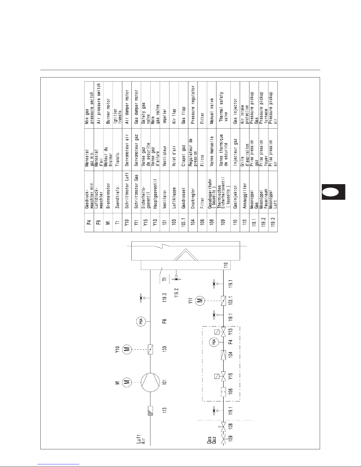
Overview
Hydraulics diagram
EN
Page 10
10
09/2005 - Art. Nr. 13 019 526A
Overview
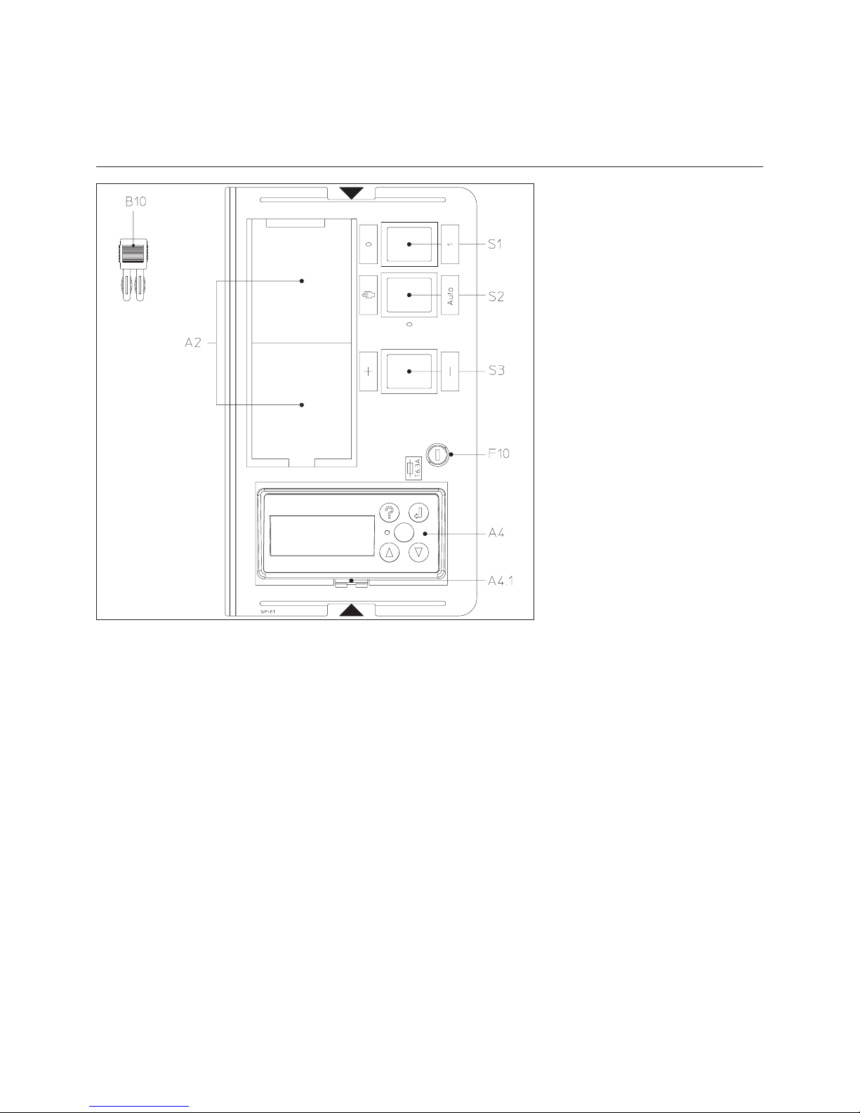
Control panel
Function
A2 Standardised position for
fitting three-point regulator
A4 Display and operating unit
A4.1 Mounting location with clips
for removing the display and
operating unit
B10 Flame signal measuring
bridge (concealed)
F10 Fuse
S1/H10 Main switch
0 Off
1On
(operating light in switch lights up).
S2 Operating mode selector
switch Auto/Manual N
S3 + Manual increase of
burner power
- Manual reduction of
burner power
All control elements are visible
externally. A removable transparent
cover clipped to the burner cover gives
access to the monitoring and control
elements for setting and operating
the burner.
The control panel contains the
switching circuit cut-out.
To remove the cover, press in one or
both sides gently and pull out at the
same time.
To replace the cover, position the two
clips at the appropriate openings and
push in.
m
N.B.:
The main switch of the control panel
only operates the control voltage.
Before working in the control area of
the burner, disconnect it fully from the
mains, incl. burner motor AC
connection.
Page 11

11
09/2005 - Art. Nr. 13 019 526A
Overview
Combustion control unit MPA22
Function description
In addition to the function of a gas
combustion control unit, the MPA 22
combustion control unit also realises
power modulation of the burner via the
actuation of air flaps and gas throttle in
an electronic connection. The electronic
connection controls the opening of the
gas throttle proportional to the air flap
along a curve based on 10 adjustment
points. During start up, the adjustment
points are defined based on the
measurement values of the exhaust
gas analysis.
This guarantees optimal combustion
across the entire performance
modulation of the burner.
With adjustment point P0, a separate
ignition load can be defined for the
burner.
The thresholds for the normal range are
defined with adjustment points “bu” and
“bo” (lower operasssting point and
upper operating point). In addition,
other optional functions, such as leak
checks, reventilation or waiting times
can be activated.
The combustion control unit is operated
via a display and operating unit.
1 Additional propane gas valve ¬
2 Safety gas valve Y15
3 Main gas valve Y13
4 Burner motor M1
5 Ignition transformer T1
6 Power 230V-50Hz
7 GW max: Bridge connector
(Safety chain inlet ¬)
8 GW min F4
9 GW VPS ¬
10 Air pressure switch F6
11 Light sensor ¬
12 Flame monitor UV/Ion ¬
13 Pulse counter ¬
14 Gas servomotor Y11
15 Air servomotor Y10
16 Display and operating unit
connection A
17 e-Bus connection ¬
18 Power regulator connection 4P
19 Boiler control panel connection 7P
¬ Option
¬
¬
¬
¬
¬
EN
Page 12

12
09/2005 - Art. Nr. 13 019 526A
·
Access to Info mode (t < 5 s).
·
Access to voice mode (t > 5 s).
·
Return to next highest program level.
· Activating a function.
· Confirming a value.
· Moving the cursor anti-clockwise.
· Increasing the marked value.
· Moving the cursor clockwise.
· Reducing the marked value.
·
Unlocking the combustion control unit.
·
Red light diode flashes in the event of a fault.
Overview
Combustion control unit MPA 22
Display and operating unit
Display
Button
Current values and operating statuses are displayed via the display and operating
unit. By activating certain keys, it is possible to switch to info mode, operating
mode or voice mode in addition to adjustment mode.
Page 13

13
09/2005 - Art. Nr. 13 019 526A
Overview
Combustion control unit MPA 22
Program structure
Adjustment mode
Enter access code
Set key data
P9/P1/P0
Start burner via
boiler regulator
for hot
adjustment
Operation at bu
(lower operating
point)
Back to
operating display
–
eBus address
–
Reventilation time
–
Waiting time
–
Pulses per L/m³
–
Rest pos. Air flap
–
Delete error list
–
Check for leaks
–
Valve 1 check time
–
Valve 2 check time
–
Address regulation
Voice mode
Parameters SettingsCountersErrors
Info mode
Burner start-up
Adjustment of
upper/lower threshold
points
Setting for points P0
to P9
Temperature
controller on
Operating mode
Ready for operation
Temperature
controller on
Operation
t>5 s
t<5 s
Start-up
Check air pressure
switch
Pre-ventilation
Safety time
Stabilization time
·
Error 0
·
Error 1
·
Error 2
·
Error 3
·
Error 4
·
Error 5
·
Fuel
·
Value P0
·
Value P1
·
Value P2
·
Value P3
·
Value P4
·
Value P5
·
Value P6
·
Value P7
·
Value P8
·
Value P9
Hot adjustment
Parameter
adjustment
Cold adjustment
Burner burns in
ignition setting
Calculation of
characteristics curve
points P2 .....P8
·
Francais
·
English
·
Deutsch
·
Italiano
·
Nederlands
·
eBus address.
·
Rest pos. Air
·
Check for leaks
·
Reventilation
·
Error list
·
Software
·
Automatic
control unit
·
Version
·
Date
·
Product
·
No.
·
Fuel
consumption (m)
·
Total operating
time (hours)
·
Successful
burner starts
EN
Page 14

14
09/2005 - Art. Nr. 13 019 526A
Boiler door preparation
·
Prepare the burner plate/boiler doors
as per the drawing.
·
Stipulate interior diameter Ø 195 mm.
·
Four M10 holes (220-260 mm
diameter circle) are required, as
indicated in the accompanying
diagram.
DE
Assembly
Burner head
Burner housing
Fitting the burner housing
·
Dismantle the mixing unit before fitting
the burner housing.
·
Undo the fixing screw (M10 counter
nut and Allen screw) on the side of
the unit (opposite the gas connection)
and withdraw the mixing unit.
If the burner housing hangs below the
burner head axis, proceed as follows:
·
Unscrew and remove the two lower
nuts on the burner housing and
unscrew the two upper nuts as far as
possible.
·
Place the burner housing sloping
diagonally forwards and fit the two
upper bolts into the two slots in
the burner head flange.
·
Press the burner housing against
the burner head flange and tighten
the 4 nuts.
The housing can be mounted above
the axis of the burner head if
required. In this case, the procedure
must be reversed.
No other positions for the burner
housing are possible.
Fitting the burner head
·
Screw M10 stay bolts into the
burner plate/boiler door and add the
insulation. If the bolt circle is <260,
cut slots to the required size.
·
Fix the burner head with 4
hexagonal nuts M10
Blast tube installation depth
On boilers with reverse firing or on
three-pass boilers, the blast tube
installation depth must be complied with
for correct operation. The following
standards are to be reconciled with the
boiler manufacturer’s specifications.
–
Boiler in reverse firing chamber
Dimension A = Boiler front to reverse
edge of second pass
–
Three-pass boiler
80-190 mm
Insertion depth
-20 to +90 mm
Insertion depth
Øa Øb c d
195 220-260 M10 45°
Page 15

15
09/2005 - Art. Nr. 13 019 526A
Assembly
Gas valve assembly
Assembly Gas valve assembly
·
Press the gas throttle module 5 against
the burner head and tighten the 4
nuts. Then secure the gas connection
pipe 3 to the gas throttle module.
Check that O-Ring 6 and flat gasket 4
are in the correct position.
·
Secure gas valve 2 so that the
solenoids of DMV SE are positioned
vertically over the gas valve.
·
Fit the supplied gas pressure tube 7
between the gas throttle module and
DMV SE.
·
If available, secure external filter 1.
·
Note the direction of the flow.
·
Fit a thermally triggered safety valve
and a gas ball valve (provided by
manufacturer) before the gas valve.
m
If the position of the gas train is
angled, use the enclosed
right-angled pressure release pipe
with screw connection.
If the gas valve is changed, the
applicable guidelines and
regulations must be observed. All
connections should be leak-tested
using foam-producing or similar
materials.
Caption
1 External filter
2 Gas valve
3 Gas connection pipe
4 Flat gasket between gas
connection pipe and gas throttle
module
5 Gas throttle module
6 O-Ring between gas throttle
module and burner head flange
7 Gas pressure tube
1
2
3
4
65
7
EN
Page 16

16
09/2005 - Art. Nr. 13 019 526A
Assembly
Checking/Setting
Mixer unit for natural gas/propane gas
Recommended setting for propane gas
On the gas diffusers labelled C, 2
outwards-facing slots and 1
inwards-facing slot should be left
covered by sleeve E.
Secure the turbulator with 5 solid
M5x6 screws (diffuser D) and 1 drilled
M5x6 screw F (diffuser C).
On the gas diffusers labelled D, 2
outwards-facing slots and 0
inwards-facing slots should be left
covered by sleeve E.
1
Checking the mixing unit
·
Check and adjust the setting of the
ignition electrodes and the
turbulator.
Recommended setting for natural gas
On the gas diffusers labelled A, 5
outwards-facing slots and 1
inwards-facing slot should be left
covered by sleeve E.
Secure the turbulator with 6 drilled
M5x6 screws F.
On the gas diffusers labelled B, 5
outwards-facing slots and 0
inwards-facing slots should be left
covered by sleeve E.
Fitting the mixing unit
·
Release and remove the mixing unit
cover by unscrewing the three Allen
screws 1.
·
Check the gas connection O-ring.
·
Fit the mixing unit and tighten with
screw at side (M10 counter nut and
Allen screw).
·
Fit the extension rod with 0-40 scale
(loose in accompanying pack) for
setting the turbulator.
·
The extension rod must be pushed
into the steel sleeve until it makes
contact.
·
Feed ignition cable 2 and ionisation
cable 3 through the opening and
push in the rubber bushing.
·
Screw down the cover, connect the
ignition cables 2 and ionisation
cable 3.
Page 17

17
09/2005 - Art. Nr. 13 019 526A
Assembly
Gas supply
Electrical supply
Electrical supply to the burner
For connection of the burner and
regulator, the corresponding circuit
diagram is mandatory.
The power supply and the electrical
connections must comply with the
applicable standards.
m
N.B.:
·
Before connecting the burner to the
electrical supply, close the gas
ball valve.
· Set the main switch of the burner
control panel to zero.
Before any intervention on the
connector of the gas and air servomotors, the display or the e-Bus connection, the burner must be switched off by
disconnecting the 7-pin plug.
Burner motor connection
The burner is delivered with a neutral
wire and earthing for a mains voltage of
400V-50Hz AC.
The connection cable for the burner
motor must be run through the cable
fittings and wired to the terminal strip as
indicated in the electrical diagram.
Check the direction of rotation of the
fan motor (see arrow on burner casing)
via manual activation of the burner
protection device.
Gas valve connection
·
Connect the gas valve to the plugs
located on the burner (black to
black, grey to grey).
·
Insert connector 1 between burner
and gas throttle servomotor in
accordance with the diagram below.
Burner and regulation connection
Insert the 4-pin and 7-pin plug of the
boiler control panel in the correspond
-
ing sockets of the burner.
General regulations for the gas supply
·
Connection of the gas valve
assembly to the gas mains must be
carried out by a recognised
specialist.
·
The cross-section of the gas cable
must be such that the prescribed
gas flow pressure at the gas valve
inlet is not undershot.
Burner start-up automatically implies
acceptance of the system. This is the
responsibility of the installer or his
representative as he alone can
guarantee that the system conforms to
the current standards and regulations.
The installer must hold a licence issued
by the gas authority, must have
checked the system for leaks and must
have vented it.
EN
Page 18

18
09/2005 - Art. Nr. 13 019 526A
Start-up
Default settings
Burner power Dimension
Y
mm
Air flap opening Gas throttle opening Pressure
adjustment
setting
pVA mbar
Low loadkWRated load
kW
Ignition
load
P0 (°)
Low load
P1 (°)
Rated load
P9 (°)
Ignition
load
P0 (°)
Low load
P1 (°)
Rated load
P9 (°)
140 400
10 0 0 25 23 23 39 15
150 500
20 0 0 29 23 23 43 15
160 600
35 5 5 40 24 24 50 15
170 700
40 5 5 45 24.5 24.5 62 15
Natural gas settings table G 05.700 MODULO
Natural gas settings table G 05.1000 MODULO
Burner power Dimension
Y
mm
Air flap opening Gas throttle opening Pressure
adjustment
setting
pVA mbar
Low loadkWRated load
kW
Ignition
load
P0 (°)
Low load
P1 (°)
Rated load
P9 (°)
Ignition
load
P0 (°)
Low load
P1 (°)
Rated load
P9 (°)
170 600
20 0 0 38 26.5 26.5 56 15
170 700
25 2 2 41 26.5 26.5 65 15
200 800
30 6 6 68 27 27 90 18.5
220 900
35 8 8 68 28 28 90 18.5
250 1000
40 9 9 68 29 2 90 18.5
Propane gas settings table G 05.700 MODULO
Propane gas settings table G 05.1000 MODULO
Burner power Dimension
Y
mm
Air flap opening Gas throttle opening Pressure
regulator
setting
pVA mbar
Low loadkWRated load
kW
Ignition
load
P0 (°)
Low load
P1 (°)
Rated load
P9 (°)
Ignition
load
P0 (°)
Low load
P1 (°)
Rated load
P9 (°)
140 400
10 4 4 20 19 19 30.5 15
150 500
20 4 4 29 19 19 36 15
160 600
30 4 4 36 19 19 41 15
170 700
40 4 4 40 19 19 45 15
Burner power DimensionY
mm
Air flap opening Gas throttle opening Pressure
regulator
setting
pVA mbar
Low loadkWRated load
kW
Ignition
load
P0 (°)
Low load
P1 (°)
Rated load
P9 (°)
Ignition
load
P0 (°)
Low load
P1 (°)
Rated load
P9 (°)
170 600
15 6 6 36 19.5 19.5 42 17.5
170 700
20 6 6 63 19.5 19.5 75 17.5
200 800
25 7 7 63 19.5 19.5 75 17.5
220 900
35 7 7 68 19.5 19.5 75 17.5
250 1000
40 8 8 68 22 22 75 17.5
The above setting data are basic settings. The factory setting data are in boxes with thick black borders. The burner can
normally be run using these settings. Check the setting values carefully in each case. System-specific corrections may be
necessary.
Page 19

19
09/2005 - Art. Nr. 13 019 526A
Start-up
Burner head position setting,
Gas pressure switch and air pressure switch
Burner head position
Dimension Y is set by turning screw V.
Set the burner head setting in accordance
with the table. The burner head setting can
influence the starting performance and
burner performance.
Gas pressure switch
·
Remove the transparent cover.
·
Set the setting scale to 5 mbar
(natural gas and propane gas).
The gas pressure switch min. is
installed between the valves. The gas
safety valve Y15 is actuated one
second before the safety time. Within
this time, the gas pressure switch must
release. If there is insufficient gas
pressure, the burner starting is
interrupted and a waiting time of 2
minutes starts. Start-up is then
attempted again. The waiting time can
only be reset by cutting the power supply
to the device.
Waiting times: 3 x 2 minutes, then 1 hour
Air pressure switch
·
Remove the transparent cover.
·
Provisionally set the air pressure
switch to the minimum setting.
Pressure regulator setting
The gas pressure regulator is set to the
default setting in the factory (see page
18). Check the gas pressure after the
first time the burner is started up
(measuring point: gas valve output
flange) and if necessary correct the gas
pressure pBr using setting screw S. Do
not change it again after start-up.
EN
Page 20

20
09/2005 - Art. Nr. 13 019 526A
Start-up
Checks before start-up
Control unit auto-test
Air Gas
Burner check
Control unit unprogrammed
Control unit auto-test
Switch the burner on via the main switch. The combustion control unit executes an
auto-test. If the control unit has not yet been programmed, the display shows
“Control unit unprogrammed”
Auto-test of the control unit and of the air and gas servomotors
This display loads the values contained in the combustion control unit.
The control unit has not yet been programmed.
Loading values
100%
0%
Pre-start-up check
·
Disconnect the burner by unplugging
it from the power supply.
·
Close gas valves.
·
Note the operating regulations of the
heat generator and regulation
producer.
·
Check that the gas type and gas
pressure are appropriate to the
burner.
·
Check the gas conduit for leaks
·
Vent the fuel supply pipes.
·
Check the flame pipe insertion depth
in accordance with the boiler
manufacturer’s instructions.
·
Check:
–
if the fresh air supply and the
exhaust gas paths correspond to the
burner power.
–
if there is water pressure in heating
circuit,
–
if the circulation pump is running,
–
if the mixer opens,
–
if the draught regulator in the
chimney opens,
–
if the power supply is in order,
–
thermostat settings,
·
Check the direction of rotation of the
fan motor (see arrow on burner
casing) via manual activation of the
burner protection device.
If all the checks were successful, then
ensure that:
·
Main switch 0/1 is set to zero
·
Manual/Auto operating type selector
switch is at the centre position
·
Gas ball valve is closed
·
Re-energise the burner.
Page 21

21
09/2005 - Art. Nr. 13 019 526A
Start-up
Access to adjustment mode
Parameters menu: Programming additional functions
Access to adjustment mode
·
Press and hold the key and after 0.5 seconds, press the key.
·
Enter the numbers for the access code with the or key.
· Confirm each number with .
· For input fields, switch back to the next highest level with .
After entering the correct code, three menus are available for selection.
Parameter: for programming additional functions.
Cold adjustment: for pre-adjusting the burner for initial start-up.
Hot adjustment: for only partial programming, e.g. after regulator
shutdown during adjustment or with subsequent
correction of the adjustment values.
Parameter
The “Parameters” menu item is selected from adjustment mode. This allows
various additional functions and function parameters to be configured.
–
E-Bus address: 03H: standard address (factory setting).
This parameter is required for communication with a PC.
The following addresses are possible: F3H, 73H, 33H, 13H.
Access to next parameter: continue with key.
–
This parameter allows you to configure a reventilation time.
Adjustment range: 0 seconds (= no reventilation) to 240 seconds
–
This parameter allows you to configure a waiting time between a regulator
shutdown and a burner restart.
Adjustment range: 0 minutes (= no waiting time) to 100 minutes
–
The pulse factor gives the number of pulses that the control unit receives from
the gas counter with the flow rate of a cubic metre of natural gas (accessory).
Adjustment range: 1 (1 pulse = 1m
3
) to 255 ( 255 pulses = 1m3).
Cold adj. Hot adj.
Parameters
?
Code ____
Accessing the adjustment settings
It is only possible to access adjustment
mode when the burner is idle (display:
“Control unit unprogrammed” or “Ready
for operation”.) To do this, set the
Manual/Auto operating type selector
switch on the burner control panel to
the centre position. In addition, the
access code must be entered to
activate adjustment mode.
N.B.:
Only a specialist with sufficient
training in and authorisation to deal
with MPA 22 may activate
adjustment mode via the access
code and adjust the burner.
The access code is located at the
bottom of the information label on
the MPA 22.
During the setup process, a timeout of
30 minutes is active, which is reset by
pressing a key on the keypad. Upon
expiry of the timeout, a safety shutdown
is executed. This ensures that a longer
operating time is not possible without
the setup process being completed. In
adjustment mode, all safety functions
are activated. A flame failure, air
pressure switch failure or an error in the
servomotor actuation leads to a
malfunction shutdown or safety
shutdown.
?
Next
E-Bus address
03H
Next Back
Reventilation time
000s
Next Back
Waiting time (0-100 min)
000 min
?
Pulses per l/m
3
?
EN
Page 22

22
09/2005 - Art. Nr. 13 019 526A
Next Back
Rest pos. Air flap
00.0°
Next Back
Delete error list
Next Back
Check for leak
Y
Next Back
Valve 1 check time
006s
Next Back
Valve 2 check time
006 s
Next Back
Address Regulation
10H
Connection setup
Save parameters
–
This parameter allows you to adjust the rest position of the air flap.
This parameter (in degrees) may be required after reventilation.
Default setting 00.0°
–
With this function, accumulated errors are deleted from the error log
(display information: “Empty”). The next new error is written under
No. 0 in the error log.
–
Leak check: Y= Yes/N= No
With this function, you can deactivate the valve leak check.
–
Valve 1 check time:
For proper execution of the leak check, at least the 6 seconds set in the
factory are required.
Adjustment range: 1-240 s
–
Valve 2 check time:
For proper execution of the leak check, at least the 6 seconds set in the
factory are required.
Adjustment range: 1-240 s
–
Address regulation (factory setting to 10H)
Other addresses are possible: F7H, F0H, 77H, 70H, 37H, 30H, 17H.
–
After confirming “Next” in the “Address regulation” menu item, the newly
adjusted parameters are saved in the control unit. The control unit then
switches back to “Ready for operation”.
Start-up
Adjustment mode
Parameters menu: programming of additional functions
Control unit unprogrammed
Page 23

23
09/2005 - Art. Nr. 13 019 526A
Start-up
Adjustment mode
Cold adjustment menu: Burner pre-adjustment
Cold adjustment (with ball valve closed)
In the “Cold adjustment” menu item, the P9/P1/P0 key data are pre-adjusted in
accordance with the setting table (page 18) for the desired burner power.
The control unit then calculates the intermediate points P2 to P8 and switches to
the “Hot adjustment” menu.
·
Accessing the adjustment mode.
·
Select cold adjustment with or .
·
Confirm with .
Adjust air and gas setting.
·
Position the cursor on air or gas with or .
·
Activate with (cursor flashes).
·
Set new value with or .
·
Confirm with .
Switch between adjustment points P9/P1/P0.
· Position cursor on “Next” or “Back” with or .
· Confirm with .
· If the position “Next” is confirmed for adjustment point P0 with , the
control unit calculates the intermediate points P2 to P8 and then switches to
the hot adjustment menu .
Direct access to this menu via adjustment mode/hot adjustment
.
?
Next
Next Back
Low load
P1
Air: .. ` . Gas: ..´ .
Next Back
Ignition load P0
?
?
start adjustment
Burner via boiler
regulator for hot adj
?
Air: .. ` . Gas: ..´ .
Air: .. ` . Gas: ..´ .
Full load P9
EN
Page 24

24
09/2005 - Art. Nr. 13 019 526A
Start-up
Adjustment mode
Hot adjustment menu: Adjusting the burner
Hot adjustment (with first start for function check, still with closed ball valve)
Hot adjustment of the burner
In the “Hot adjustment” menu items, the fine adjustments for the air and gas flap
are made for the ten adjustment points P0 to P9 using the exhaust gas analysis.
Then, the definitive working range of the burner is defined based on the bu (lower
operating point) and bo (upper operating point) thresholds.
Note: if normal shutdown takes place during the adjustment procedure,
select the “Hot adjustment” menu item immediately after activating
adjustment mode. By doing this, you will keep the values of the points that
have already been adjusted, while a recalculation is carried out in the “Cold
adjustment” menu.
·
For burner start, set the Manual/Auto burner selector switch to manual on the
control panel, ensure heat request via boiler regulator.
The burner starts with the following function sequence:
–
Air flap opens for ventilation. Air: .........................
–
Blower motor on. ....................................
–
Check air pressure switch
–
Pre-ventilation 20 seconds: time remaining is displayed.
–
Gas throttle moves to ignition position. Gas: .................
–
Servomotor air flap moves to ignition position. Air: ............
–
Ignition on .........................................
Because the ball valve is closed, the burner shuts down after the safety time as the
gas pressure is too low.
The display shows: “Gas pressure too low”.
·
If the function check was successful, the gas valve is opened.
After a two-minute waiting time, the burner is automatically restarted and the
above-mentioned process is repeated.
–
Valve energised. ....................................
–
Safety time 3 seconds. After the safety time, the ignition transformer is
de-energised.
–
Flame signal present. .................................
During the stabilisation time, the burner remains in ignition setting.
Burner check
Air: - Gas: -
Start-up
Air pressure check
Pre-ventilation: 20 s
Air: - Gas:
Pre-ignition
Air: Gas: -
Safety time
Stabilisation time
Air: Gas: -
Air: - Gas: -
Air: - Gas: -
Air: - Gas: -
Page 25

25
09/2005 - Art. Nr. 13 019 526A
Start-up
Adjustment mode
Hot adjustment menu: adjusting the burner
Next
Ignition load P0
Air: .. ` . Gas: ..´ .
Next Back
Low load P1
Next Back
Adjustment point P2
Point P3 .... Point P8
Next Back
Full load P9
Next
Lower load point bu (lower
operating point)
Next
Upper load point bo
(upper
operating point)
Operation
Burner remains in ignition load, adjustment point P0.
·
Check gas pressure pBr (for factory setting, see default setting on page 18).
In the event of a later change, all adjustment settings must be corrected.
Therefore, start fine adjustment of the burner at P9. In each adjustment point,
check the combustion values and, if necessary, change the gas throttle setting
or air flap setting. To do this:
·
Select air or gas with or .
·
Activate with (cursor flashes).
·
Change value with or .
·
Confirm with .
Access to the next adjustment point by selecting Next and confirm by pressing key .
Important:
The values for each adjustment point are only saved when you access the
next adjustment point.
·
Enter the adjustment values in the log (page 30).
·
Move the individual adjustment points to point 9 (full load).
· Check gas flow rate full load, if necessary increase or reduce gas and air.
· If all adjustment points from P0 to P9 are optimised in adjustment point P9,
confirm with “Next” .
The burner moves to the lower operating point (bu).
· Check the low load exhaust gas temperature and gas flow rate, if necessary
adjust the burner power by correcting bu (lower operating point).
· Confirmation “Next”.
The burner moves to the upper operating point (bo).
·
Check the high load exhaust gas temperature and gas flow rate. If necessary
adjust the burner power by correcting bo (upper operating point). The
adjustment is made by changing the air flap.
·
Confirm with “Next” to complete the adjustment procedure. The burner
switches to operating mode.
·
Burner moves to lower operating point and waits for a request for heat.
·
Manual/Auto operating type selector switch to manual: burner power can be
changed manually via the +/- switch.
·
Manual/Auto operating type selector switch to Auto:
burner adjusts bu/bo within the specified power range in accordance with the
requirements of the regulation thermostat.
Adjust air pressure switch
·
When the burner is running at rated load, calculate the blower pressure.
·
Set air pressure switch approx. 15% below calculated value.
Air: .. ` . Gas: ..´ .
Air: .. ` . Gas: ..´ .
Air: .. ` . Gas: ..´ .
Air: .. ` . Gas:
Air: .. ` . Gas:
Air: .. ` . Gas:
EN
EN
Page 26

26
09/2005 - Art. Nr. 13 019 526A
Start-up
Operating mode
Burner check
Air: Gas:
Start-up
Air: Gas:
Air pressure check
Pre-ventilation: 20 s
Pre-ignition
Safety time
Stabilisation time
Operation
Burner ready for operation
Boiler thermostat requests heat.
Burner start flowchart:
The burner starts with the following function sequence:
–
Air flap opens for ventilation. Air: .........................
–
Blower motor on. ....................................
–
Pre-ventilation 20 seconds: time remaining is displayed.
–
Gas throttle moves to ignition position. Gas: .................
–
Air flap moves to ignition position. Air: .....................
–
Ignition on .........................................
–
Valve energised. ....................................
–
Safety time 3 seconds
–
Flame formation. ....................................
After the safety time, the ignition transformer is de-energised.
·
During the stabilisation time, the burner remains in ignition setting.
·
The burner is in operation and adjusts bu (lower operating point) to bo
(upper operating point) within the specified performance range
(manual/Auto operating type selector switch to Auto). The current setting
of the air flap is displayed.
Standby
Air: Gas:
Air: Gas:
Air: Gas:
Air: Gas:
Air: Gas:
Air: Gas:
Page 27

27
09/2005 - Art. Nr. 13 019 526A
Start-up
Info mode
Voice mode
·
Press key t < 5s.
·
Select desired menu with or .
·
Confirm selected menu with .
· Scroll with or .
· Return to the next highest level with .
Error Counter
Parameter Setting
?
Establishing connection
?
0% 100%
Info 1
Info 2
?
Info 3
Parameters SettingsCountersErrors
Comment: info mode can be activated
with the button during burner operation
and burner idle time. To exit info
mode, press the button again.
·
Error 0
·
Error 1
·
Error 2
·
Error 3
·
Error 4
·
Error 5
·
Fuel Gas.
·
Value P0
·
Value P1
·
Value P2
·
Value P3
·
Value P4
·
Value P5
·
Value P6
·
Value P7
·
Value P8
·
Value P9
Voice mode can be activated with the button during burner operation and burner
idle time.
·
Press button t > 5s .
·
Select desired language with or .
·
Scroll with or (5 languages possible).
·
Confirm selected language with . This will close voice mode.
FRANCAIS
ENGLISH
DEUTSCH
DEUTSCH
ITALIANO
NEDERLANDS
·
eBus address.
·
Rest pos. Air
·
Check for leaks
·
Reventilation
·
Error list
·
Software
·
Automatic
control unit
·
Version
·
Date
·
Product
·
No.
·
Fuel
consumption (m)
·
Total operating
time (hours)
·
Successful
burner starts
EN
Page 28

28
09/2005 - Art. Nr. 13 019 526A
Burner and boiler servicing can only
carried out by a trained specialist.
The system operator is advised to
take out a service contract to
guarantee regular servicing.
N.B.:
Before maintenance and cleaning work,
completely separate the burner from
the mains, including the power supply
AC motor, and close the gas ball valve.
A1 Combustion control unit
A4 Display and operating unit
B10 Ionisation bridge
F6 Air pressure switch
F12 Protective motor relay
K1 Motor contactor
M1 Burner motor
T1 Ignition transformer (concealed)
Y10 Servomotor air flap
7 Control panel
8 Blast tube
13 Burner cover
113 Air box
Maintenance
Checking the exhaust gas temperature
·
Check the exhaust gas temperature.
·
Clean the boiler if the exhaust gas
temperature is over 30 K above the
start-up value.
Checking the ignition electrodes
and the mixing unit.
·
Disconnect the 2 ignition cables
from the ignition transformer.
·
Remove the grommet for the two
cables from the cover by pressing
into the burner head.
·
Unscrew completely the 3 screws
securing the cover.
·
Slip the cover off over the cables.
·
Loosen the side screw securing the
mixing unit.
·
Pull out the mixing-ignition unit.
·
Check the condition of the turbulator.
·
Check the position of the ignition
electrodes and the turbulator.
·
If necessary, remove dust from the
parts accessible with the cover
removed.
·
Check the presence and condition of
the O-ring seal J1 when assembling.
Cleaning the fan
·
Disconnect the motor by unplugging
it from the power supply.
·
Unscrew the 7 screws of the motor panel.
·
Remove the panel and motor, taking
care not to damage the gas
pressure tube of the differential air
pressure switch.
·
“Dry” clean the air pressure pipes.
·
Do not use pressurised materials.
·
Take out the 4 screws securing the
air guiding piece.
·
Thoroughly clean the air duct and fan.
·
Reassemble.
Page 29

29
09/2005 - Art. Nr. 13 019 526A
Valves
No special maintenance is required for
the valves.
Valves must not be repaired.
Defective valves must be replaced by a
qualified professional, who must check
the leak, function and combustion
values following replacement.
Remove the blast tube.
To carry out this procedure, the
combustion chamber door must be
opened or the burner removed.
–
Variant 1 -Access via the
combustion chamber doors
·
Remove the mixer control/ignition
device.
·
Loosen the 3 fixing screws on the
blast tube support by 1 to 2 turns.
N.B.: the screws are threaded to the
left (Allen 3).
·
Remove the blast tube, check,
clean, and where necessary, replace
if a deformity is found.
·
Refit the blast tube in the reverse
sequence.
·
The space between the blast tube
and the door insulation should be
fitted with flameproof material.
–
Variant 2 - Removing the burner
·
Remove the mixer control/ignition
device.
· Loosen the electrical connections.
· Remove the gas valve assembly.
· Unscrew the gas connection
(2 M8 nuts).
· Loosen the burner housing
(2 M8 screws) and remove.Do not
damage electrical cables.
· Unscrew the burner head and then
proceed as under variant 1.
· Refit in the reverse sequence.
Precautions
After each intervention, check the
combustion performance under real
operating conditions (doors shut,
cover fitted etc.).
Note down the results in the
corresponding report forms.
Replacing the filter on the gas valve
The filter must be checked once a year
and replaced if dirty.
Pocket filter:
·
Release the cover fixing screws on
the filter.
·
Remove the filter.
·
Insert new filter.
·
Refit the cover with the screws.
Tube filter:
·
Dismantle the gas connection flange
at the inlet side.
·
Remove the filter.
·
Insert new filter.
·
Fit a gas connection flange.
·
Open the manual stop valve; check
tightness.
Cleaning the hood
·
Clean the cover with water and a
cleaning product.
·
Do not use chlorine-based or
abrasive cleaning products.
Maintenance
EN
Page 30

30
09/2005 - Art. Nr. 13 019 526A
Burner-specific adjustment settings of the MPA 22
Measurement/Date:
Parameters Dim Range M1/ M2/ M3/ M4/
eBus address
Reventilation time [s] 0-240
Waiting time [min] 0-100
Pulses per L/m³ 1-255
Rest pos. Air flap [°]
Delete error list blank/
Check seals Y/N
Valve check time 1 [s] 0-240
Valve check time 2 [s] 0-240
Address regulation
Software
Product No.
Counters Dim.
Fuel consumption [m³]
Total operating hours [hours]
Successful burner starts
Measurement/Date:
M1/ M2/ M3/ M4/
Measurement Measurement
Air M1 M2 M3 M4 Gas M1 M2 M3 M4
Value P0 [°] [°]
Value P1 [°] [°]
Value P2 [°] [°]
Value P3 [°] [°]
Value P4 [°] [°]
Value P5 [°] [°]
Value P6 [°] [°]
Value P7 [°] [°]
Value P8 [°] [°]
Value P9 [°] [°]
bu/flow rate [°] [m³/h]
bo/flow rate [°] [m³/h]
bu/Value CO2/CO [%] [ppm]
bo/Value CO2/CO [%] [ppm]
System: ..........................................
Burner No.: .....................................
Boiler manufacturer: ...............................
Boiler type: ..............................................
Observer M1: .....................................................
Observer M2: .....................................................
Observer M3: .....................................................
Observer M4: .....................................................
Page 31

31
09/2005 - Art. Nr. 13 019 526A
Service
Troubleshooting
Fault diagnosis and repair
Before carrying out fault diagnosis,
check that the basic requirements for
correct operation are being fulfilled:
·
Is there any current?
·
Is there any gas pressure?
·
Is the gas stop valve open ?
·
Are all control and safety devices,
such as the boiler thermostat,
low-water detector, limit switch, etc.
adjusted properly?
Error/fault Cause Corrective action
Display without information No mains voltage present
External cut-out defective
Display-control unit plug-and-socket
connection interrupted
Display defective
MPA 22 defective
Check
Check/replace
Check/establish connection
Replace
Replace
Display “Safety chain” No feedback on terminal 7 Insert bridge connector or given
Check switch/limiter
Motor does not start Control unit-motor plug-and-socket
connection interrupted
Capacitor defective
Motor defective
Control unit/servomotors feedback not
correct
Establish connection
Check/replace
Check/replace
Control unit/servomotors
Check/replace
Motor only runs briefly Air pressure switch does not activate
Gas pressure switch does not activate
Gas filter dirty
Magnetic valve V1 does not open
No gas available
Check/change adjustment
Check/change adjustment
Clean/replace gas filter
Check/replace compact valve
Notify gas supplier
Note: in the event of a gas shortage,
the waiting time can be reset by
de-energising the burner (7-pin plug)
Burner does not start Compact valve defective
Ignition transformer defective
Ignition electrode position/Ignition cable
MPA 22 control unit defective
Ionisation probe/IRD probe
Replace
Replace
Check/replace
Check/replace
Check/replace
Crack formation on ionisation probe Too much gas on probe
Circulation insufficient
Fit solid screws (propane gas set)
If a fault occurs on the burner, the red
light diode flashes on the display unit.
At the same time, the cause of the fault
is displayed and a fault code is
displayed.
EN
Page 32

32
09/2005 - Art. Nr. 13 019 526A
Adresse Service-Hotline
ELCO Austria GmbH
Aredstr.16-18
2544 Leobersdorf
0810-400010
ELCO Belgium n.v./s.a.
Pontbeeklaan-53
1731 Zellik
02-4631902
ELCOTHERM AG
Sarganserstrasse 100
7324 Vilters
0848 808 808
ELCO GmbH
Dreieichstr.10
64546 Mörfelden-Walldorf
0180-3526180
ELCO France
18 rue des Buchillons
74106 Annemasse
0450877624
ELCO-Rendamax B.V.
Amsterdamsestraatweg 27
1410 AB Naarden
035-6957350
Fabriqué en EU. Made in EU. Hergestellt in der EU. Gefabriceerd in de EU
Document non contractuel. Non contractual document. Angaben ohne Gewähr.
Niet-contractueel document
AT
BE
CH
FR
DE
NL
 Loading...