

elco VB 2.** VD Series, VB 2.66 VD, VB 2.54 VD, VB 2.45 VD, VB 2.38 VD Operating Instructions Manual
...Page 1
en
Operating instructions
VB 2.. VD
de, fr................................. 4200 1046 8002
it, nl.................................. 4200 1046 8102
en..................................... 4200 1046 8202
......................................... 4200 1068 3900
......................................... 420 110 084 400
de, fr, it, nl, en................. 4200 1046 7903
For specialist installation engineers
Fuel oil burners
02/2016 - Art. Nr. 4200 1046 8202A
Page 2

Overview
Contents
General information Contents ...............................................................................................................................................2
Operation Operating mode, safety function...........................................................................................................4
Assembly Burner assembly, burner installation position ....................................................................................11
Commissioning
Servicing Maintenance .................................................................................................................................25-26
Important information
VB2.. VD blue-flame burners are
designed for the low-pollution
combustion of extra light fuel oil in
accordance with the following standards:
AT: ÖNORM C1109: standard and low
sulphur
BE: NBN T52.716: standard and NBN
EN 590: low sulphur
CH: SN 181160-2: standard and low
sulphur
DE: DIN 51603-1 : standard and low
sulphur
DINV 51603-6 ELA BIO 10
The design and function of the burners
meet standard EN 267.
Assembly, start-up and maintenance
must only be carried out by authorised
specialists and all applicable guidelines
and regulations complied with. This
device is not designed for use by
individuals (including children) whose
physical, sensory, or mental abilities are
reduced, or by persons lacking in
experience and/or knowledge, unless
supervised by a person responsible for
their safety or if they are following the
latter's recommendations concerning the
use of the device.
Children must be supervised to ensure
they do not play with the device.
Burner description
VB2.. VD blue-flame burners are 2-stage
monoblock type devices. The special
design of the burner head with internal
recirculation of the combustion gases
provides highly efficient, low-polluting
combustion. According to tests as
defined by EN267, the values produced
comply with emissions class 3, the most
stringent standard, and with the
requirements of following national
legislation relating to the environment:
AT: KFA 1995, FAV 1997
CH: OPAir 2005
DE: 1.BImSchV
Important information............................................................................................................................2
Burner description.................................................................................................................................3
Automatic combustion control unit.....................................................................................................5-7
Terminal allocation chart, connection socket .....................................................................................8-9
Fuel oil burner pump.......................................................................................................................... 10
Electrical connection/oil connection ...................................................................................................12
Checks before commissioning, setting data ..................................................................................... 13
checking the combustion components,
recirculation ........................................................................................................................................14
Fuel oil pressure regulation, air regulation..........................................................................................15
Adjusting burner output..................................................................................................................16-24
Troubleshooting ..................................................................................................................................27
Fault diagnosis menu,
Operating statistics menu ..............................................................................................................28-29
They are suitable for use with all heat
generators complying with standard EN
303 or for use by hot air generators
complying with DIN 4794 or DIN 30697
within their respective performance
range. Any other type of application
requires the approval of ELCO.
Packaging
The following are included in the burner
packaging:
1 connecting flange with insulating
gasket
1 bag containing fittings
1 bag containing technical
documentation
1 blast tube
1 setting template
The following standards should be
observed in order to ensure safe,
environmentally sound and energyefficient operation:
EN 226
Connection of fuel oil and gas burners
with blast air to the heat generator
EN 60335-1, -2-102
Safety of electrical equipment for
domestic use
Place of installation
The burner must not be operated in
rooms with aggressive vapours (e.g. hair
spray, tetrachloroethylene, carbon
tetrachloride), high levels of dust or high
air humidity (e.g. laundry rooms).
If no connection to an air exhaust system
is provided for the air supply, a supply air
inlet with the specifications set out below
must installed:
DE: up to 50 kW: 150 cm
for every further kW: + 2.0cm
CH: Calorific power [kW] x 6 = … cm2;
but at least 200 cm
Variations may arise as a result of local
regulations.
2
2
2
We cannot be held liable for any
damage caused by the following
situations:
- unauthorised use
- incorrect installation and/or repair on
the part of the buyer or any third party,
including the fitting of non-original
parts.
Final delivery and instructions for use
The firing system fitter must supply the
operator of the system with operating
and maintenance instructions on or
before final delivery. These instructions
should be displayed in a prominent
location at the point of installation of the
heat generator. They should include the
address and telephone number of the
nearest customer service centre.
Advice to the user
The system should be inspected by a
specialist at least once a year.
Depending on the type of installation,
shorter maintenance intervals may be
necessary! The system operator is
advised to take out a maintenance
contract to guarantee regular servicing.
02/2016 - Art. Nr. 4200 1046 8202A2
Page 3
en
Overview
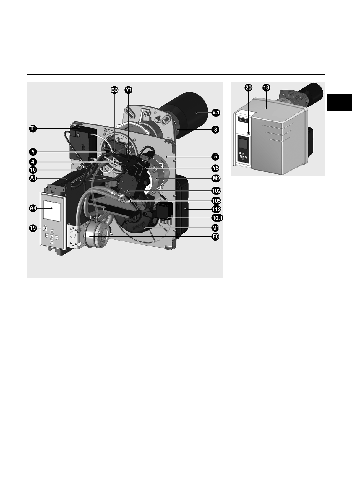
Burner description
A1 Control and safety unit
A4 Display
B3 Flame detector
M1 Fan motor
M2 Pump motor
T1 Igniter
Y Adjusting screw dimension Y
(recirculation)
4 Nozzle line tube
5 Base plate
8 Burner pipe
8.1 Flame tube (supplied disassembled)
10 7-pin connector (hidden)
10.1 4 pin connector
18 Cover
19 Release knob
20 Hood securing screw
102 Fuel oil pump
105 Fuel oil hoses
113 Silencer
Y1, Y5Solenoid valves
02/2016 - Art. Nr. 4200 1046 8202A 3
Page 4
Operation
Operation
Safety function
Heating function
If the system demands heat, the preheater is switched on first.
When the oil preheating temperature is
reached, a thermostat in the pre-heater
activates the program sequence. The
heating time with cold start is
approximately 2 minutes.
Starting the burner
- If heat is requested by the boiler
regulator, the automatic oil
combustion control unit starts the
program sequence.
- The fan motor starts, air pressure is
checked.
- Pre-ventilation
- The pump motor and ignition are on.
- Solenoid valve 6 opens, the pressure
is regulated via the pressure controller
5.
- Flame formation.
- The ignition is switched off.
Burner mode, control between partial
and full load
The burner is equipped with a nozzle
and operates at two different fuel oil
pressures (partial load and full load).
These pressures are controlled
independently by two regulators fitted in
the pump. If an increase in load is
requested by the boiler regulator, the
burner switches from partial load mode
to full load mode after a delay of
approximately 13 seconds.
- The fan motor 10 reaches the speed
for full load mode.
- If the fan speed (quantity of air) is
adjustable, the solenoid valve 3
closes, the partial load pressure
controller 5 is deactivated and the full
load pressure controller 2 regulates
the pressure.
- The fan motor continues to run at the
maximum load speed, and maximum
load mode is active.
Safety function
A lockout occurs on the device:
- if a flame signal is present during preventilation (stray light monitoring)
- if, when the burner starts up (fuel
release), no flame is produced after 5
seconds (safety time)
- if no flame is produced in the event of
flame failure during operation after
repeated unsuccessful attempts to run
the program.
A safety shutdown is indicated by the
fault indicator lamp lighting up; the fault
can then be acknowledged by pressing
the reset button after the cause of the
fault has been rectified.
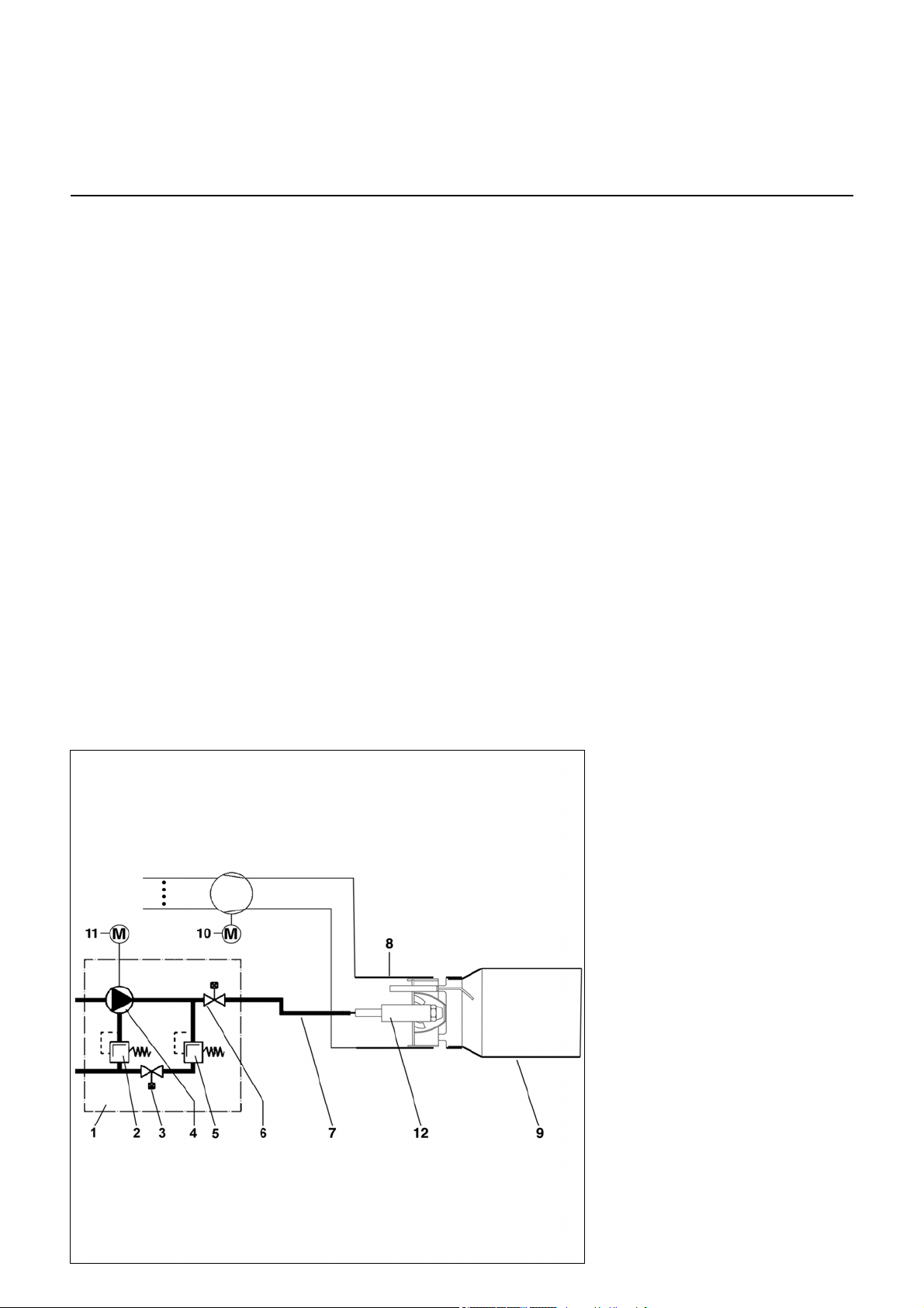
Schematic diagram
1 Two-stage pump
2 Oil pressure regulator, full load
3 Solenoid valve, full load (NO)
4Pump
5 Oil pressure regulator, partial load
6 Solenoid valve (NC)
7 Nozzle line
8 Burner pipe
9Flame tube
10 Blower motor
11 Pump motor
12 Oil preheating
02/2016 - Art. Nr. 4200 1046 8202A4
Page 5

en
Operation
TCH 24x control unit
The TCH 24x fuel oil automatic
combustion control and safety unit
controls and monitors the forced draught
burner. The microprocessor-controlled
program sequence ensures maximum
stability of time periods, regardless of
fluctuations in the power supply or
ambient temperature. The control and
safety unit is equipped with a device to
protect against the effects of brownouts.
Whenever the supply voltage drops below
its rated minimum level (< 185V), the
control unit shuts down - even in the
absence of a malfunction signal. The
control unit switches itself back on again
once the voltage has returned to normal
levels (> 195V).
Pressing and
holding the
unlocking button
for...
... 1 second ... the control and
... 2 seconds ... the control and
... 9 seconds ... Deleting the control
… causes ….
safety unit to unlock.
safety unit to lock
unit statistics
Locking and unlocking
The control unit can be locked using the
release knob or unlocked as long as
the unit is powered on.
Always switch off the power supply
before installing or removing the
control unit. Do not attempt to
open or carry out repairs on the
control unit.
Moves the cursor upwards
Moves the cursor downwards
Increases the marked value
Reduces the marked value
Modifies/confirms the value shown
Unlocks the control and safety unit
Red LED (flashes if failure occurs)
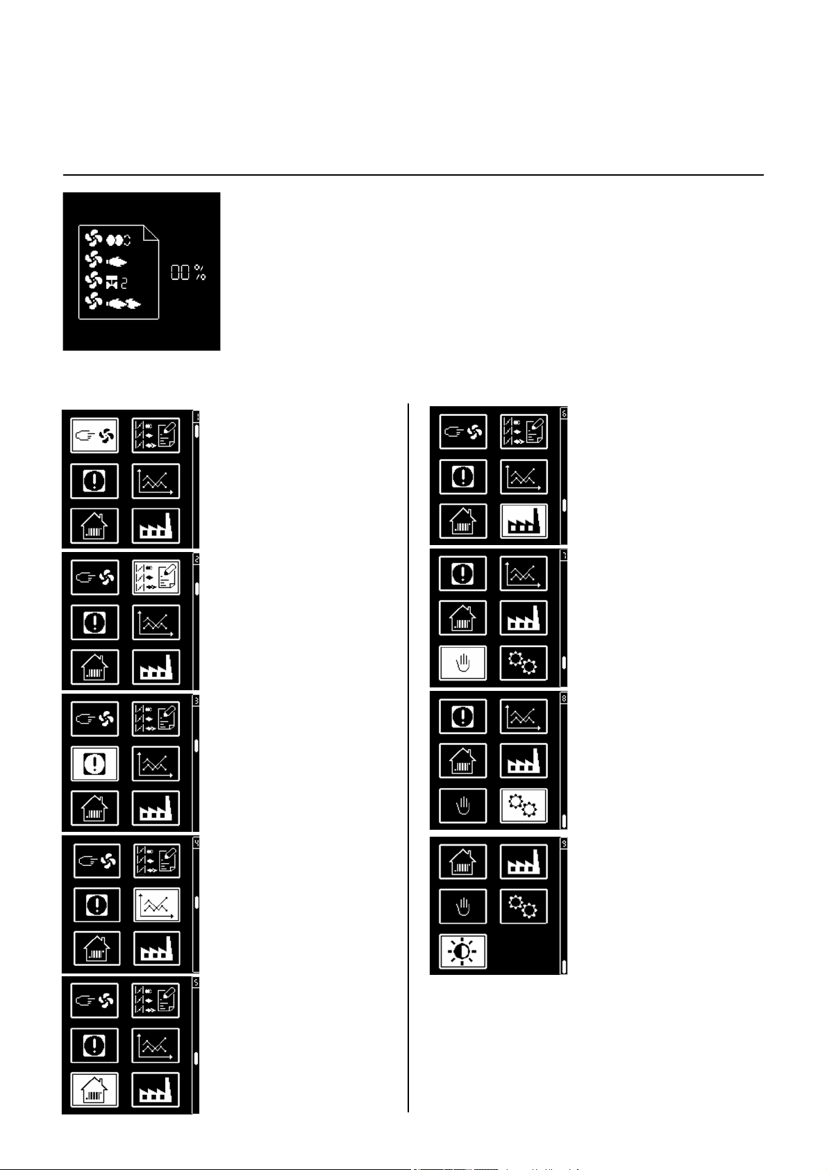
Display Description Display Description
Waiting for boiler heating
request
Waits for pre-heater
The ventilation speed increases
until it reaches the setting value
for pre-ventilation
Pre-ventilation and pre-ignition
The ventilation speed
decreases until it reaches the
setting value for the ignition
position
Oil valve is opened,
safety time
Flame is present, awaiting
authorisation of regulation
Burner in operation. The lower
line shows the strength of the
flame signal and the operating
time of the burner
02/2016 - Art. Nr. 4200 1046 8202A 5
Page 6
Operation
TCH 24x control unit
In parallel with its control and safety functions,
the TCH 24x control unit allows the following
to be set:
- the ventilation speed during ignition
- the 1st stage ventilation speed
- the ventilation speed by opening the 2nd
stage valve (for switching from 1st to 2nd
stage)
- the 2nd stage ventilation speed
- the ventilation speed by closing the 2nd
stage valve (for switching from 2nd to 1st
stage)
• Ventilation speed
setting menu in the
setting points
• Ventilation speed
display menu in the
setting points
The parameters for the control and safety unit
are set using the display and 5 keys.
Operating values are shown in real time on
the display.
Pressing the keys gives access to 9 menus:
• Industrial applications
setting menu*
• Manual control menu*
• Fault diagnosis menu
• Operating statistics
menu
• Setting/modification
menu for standard
configurations*
• Configuration mode
menu*
• Screen brightness and
contrast setting menu
* In these menus, it is
possible to adjust the
control unit's standard
configurations. These
are pre-set in the
factory. No
modifications may be
carried out on-site
without prior
consultation with ELCO.
The access code and
the setting setpoints for
these menus are
available on request.
02/2016 - Art. Nr. 4200 1046 8202A6
Page 7
en
Operation
TCH 24x control unit
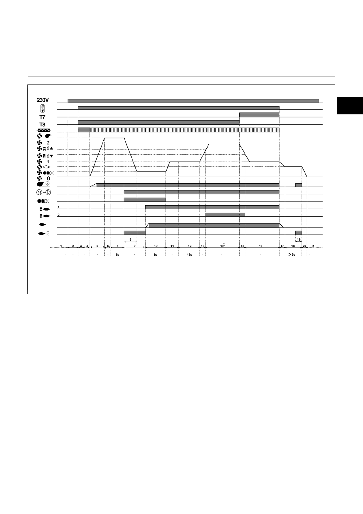
Program sequence phases:
1: No voltage
2: Powering up, no heating request
3: Heating request, Verification of fan
zero speed, pre-heater on
4: Checking the rest status of the air
pressure switch
5: Fan speed is increased to the pre-
ventilation position
6: Checking the air pressure
7: Pre-ventilation
8: The fan speed is decreased to the
ignition position, pre-ignition and
switching on of the pump motor
9: Stray light monitoring
10: Burner start-up: opening of the 1st
stage solenoid valve, flame
formation
11: Stabilisation time, the fan speed is
increased to the 1st stage
12: Awaiting authorisation for
regulation
13: The fan speed is increased to the
2nd stage valve opening value
14: Operation in 2nd stage
15: The fan speed is decreased to the
2nd stage valve closing value
16: Operation in 1st stage
17: Regulation cut-out, fan speed is
decreased to the post-ventilation
position
18: Post-ventilation time
19 : Stray light and air pressure
monitoring at the end of the post-
ventilation time
20: The fan speed is reduced to 0
- Awaiting a new heating request
02/2016 - Art. Nr. 4200 1046 8202A 7
Page 8
Operation
Earth
Pre-heater
Flame
monitor
Fault
display
Air
pressure
switch
Ignition
Blower motor
2nd stage
solenoid valve
Connector
Terminal
Terminal
Connector
Remote
unlocking
L1 power
supply
1st stage
solenoid valve
3rd stage
solenoid valve
2nd stage
thermostat
Heating
request
Earth
Fuel oil
pump motor
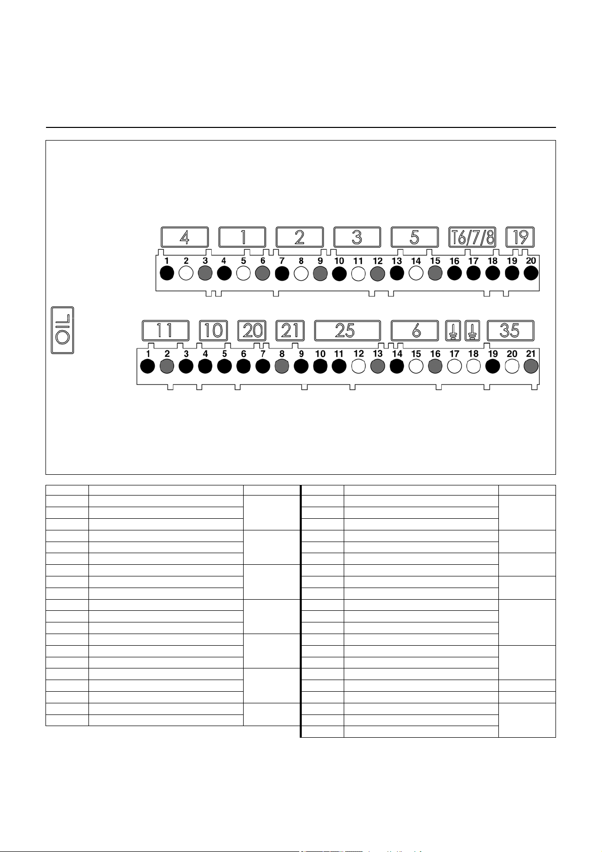
Terminal allocation chart
230 Volt connection
Terminal Description Connector Terminal Description Connector
1
2
3
4
5
6
7
8
9
10
11
12
13
14
15
16
17
18
19
20
Burner motor live
Earth
Neutral conductor
1st stage solenoid valve live
Earth
Neutral conductor
2nd stage solenoid valve live
Earth
Neutral conductor
3rd stage solenoid valve live
Earth
Neutral conductor
Ignition transformer live
Earth
Neutral conductor
2nd stage thermostat live (T6)
Signal T7
Signal T8
1st stage thermostat live (T1)
Heating request signal (option T2)
T6/7/8
19
4
1
2
3
5
1
Flame detector signal
2
Neutral conductor
3
Live
4
Live
5
Air pressure switch signal
6
Live
7
Remote unlocking signal
8
Neutral conductor
9
Malfunction signal live
10
Live
11
Pre-heater/authorisation contact
12
Earth
13
Neutral conductor
14
Live L1
15
Earth
16
Neutral conductor
17
18
19
20
21
Earth
Earth
Fuel oil pump live
Earth
Neutral conductor
11
10
20
21
25
6
35
02/2016 - Art. Nr. 4200 1046 8202A8
Page 9
en
Display/PC interface
Fan motor speed regulation control
Connector
Terminal
Terminal
Connector
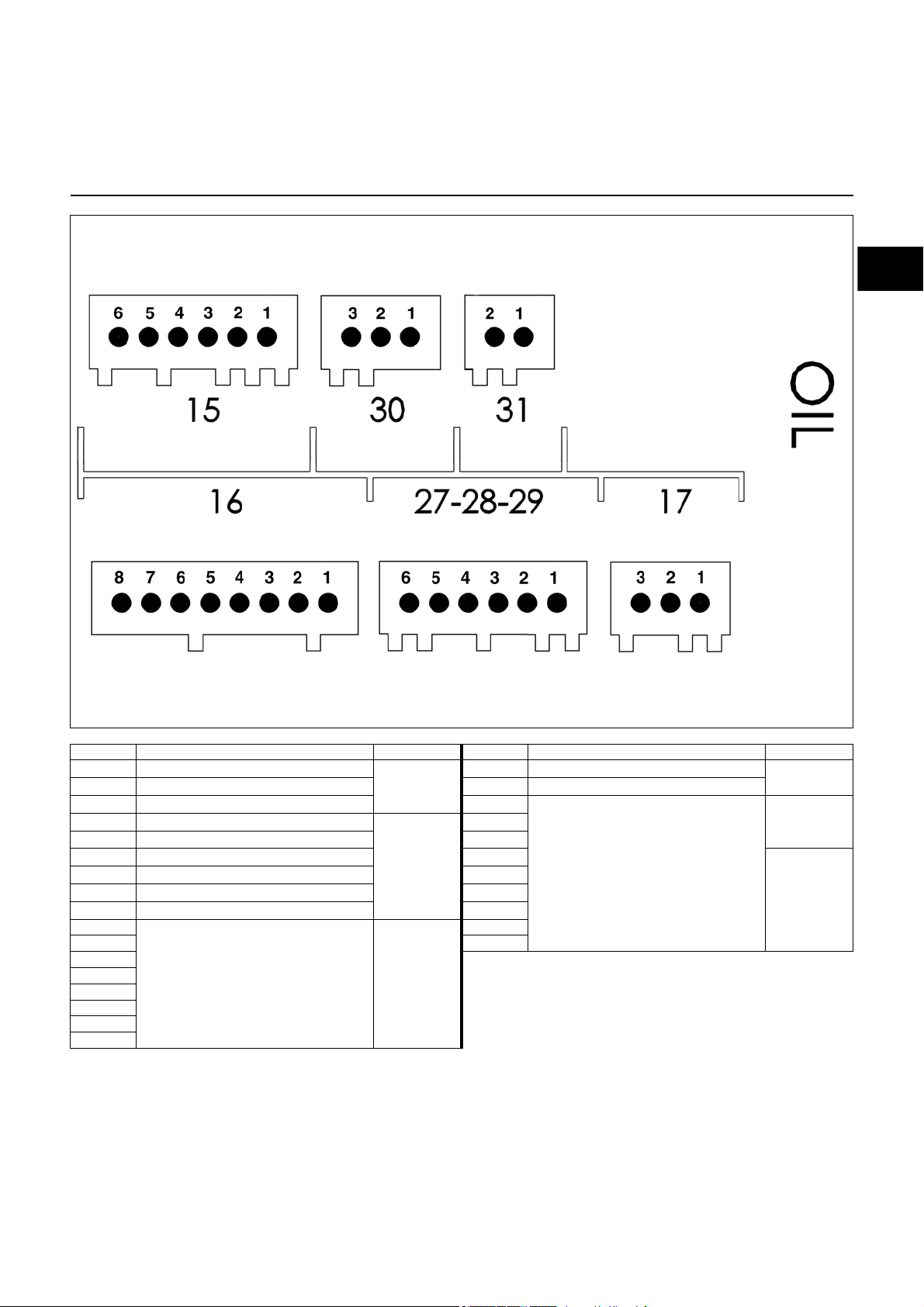
Operation
Terminal allocation chart
Low voltage connections
Terminal Description Connector Terminal Description Connector
1
Not used
2
Not used
3
Not used
1
Not used
2
Not used
3
Not used
4
Not used
5
Not used
6
Not used
1
26
3
4
Display or PC interface
5
6
7
8
17
27
28
29
16
1
Not used
2
Not used
1
2
3
1
Fan motor speed regulation control
2
3
4
5
31
30
15
02/2016 - Art. Nr. 4200 1046 8202A 9
Page 10
Operation
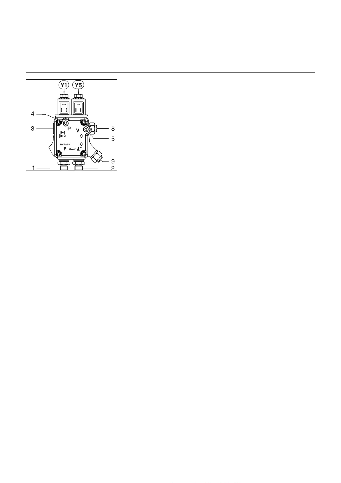
Pump
This is a gear pump. It must be
connected as a two-line pump via a
bleed filter. For the connection of the fuel
oil tank and the bleed filter, it is better to
use the single line option. An intake filter
and two oil pressure regulators are
integrated in the pump. Pressure
gauges for pressure measurements 4
and negative pressure measurements 5
must be connected before the
equipment is commissioned.
1 Return connection G1/4
2 Vacuum connection G1/4
3 Nozzle supply line connection G1/8
4 Pressure gauge connector
5 Vacuum gauge connector
8 1st stage pressure setting
9 2nd stage pressure setting
Y1 Solenoid valve, 1st stage
Y5 Solenoid valve, 2nd stage
02/2016 - Art. Nr. 4200 1046 8202A10
Page 11

en
Installation
Burner installation
Burner installation location
Burner installation
The burner flange 3 features three
elongated slots and can be used for a
drilling Ø of 150 to 170 mm (VB2.38/54
VD) and/or of 150 to 184mm (VB2.66/95
VD). These dimensions comply with
EN 226.
Sliding pipe bracket 2 on the burner pipe
makes it possible to adjust the installed
depth of the combustion components to
the respective geometry of the combustion
chamber. The installed depth remains the
same during fitting and removal.
Pipe bracket 2 secures the burner to the
connecting flange and therefore to the
boiler. This completely seals off the
combustion chamber.
Fitting the flame tube
• After installing the burner, open the
boiler door.
• Fit the flame tube 6 on the burner pipe
7 and turn clockwise until the bayonet
joint 8 is securely in place.
Installed depth of the burner
The installed depth of the burner must
be set so that the rear edge 9 of the
recirculation orifice 10 is set at the same
level as the boiler door insulation 11.
Carefully close the boiler door. Ensure
that the pivoting clearance radius of
flame tube 6 is respected.
If necessary, move the burner back
slightly and then cut the insulation as
needed.
Installation:
• Secure connecting flange 3 to the boiler
using screws 4.
• Fit pipe bracket 2 to the burner pipe and
secure using screw 1. Tighten screw 1
to a maximum torque of 6 Nm.
• Turn the burner slightly, guide it into the
flange and secure using screw 5.
Removal:
• Unscrew screw 5.
• Turn the burner out of the bayonet
socket and pull it out of the flange.
The recirculation orifice must be
positioned in the furnace so that it is
completely unobstructed and easy to
access, to allow flue gases to return
unhindered. This orifice must never
be obstructed by insulating material.
Exhaust system
To prevent unpleasant noise emissions,
right-angled connectors should not be
used on the flue gas side of the boiler.
The minimum distance between the
front edge of the flame tube and the
bottom of the furnace can be calculated
using the following formula:
70 x Q (Q=quantity of fuel oil in kg/h).
For a minimum length of the furnace of
L
, the result is:
F
L
= e + Lt + 70 x Q
F
(VB 2.38...45) = 164
L
t
L
(VB 2.54...95) = 204
t
02/2016 - Art. Nr. 4200 1046 8202A 11
Page 12

Installation
Electrical connection
Fuel oil connection
All electrical installation and
connection work must only be carried
out by a suitably qualified service
engineer. All applicable regulations
and directives must be observed.
Electrical connection
• Check to ensure that the power supply
is as specified (230V, 50 Hz single
phase with neutral and earth).
Boiler fuse: > 6.3A
Fuel oil connection
The fuel oil connection must be made
via a bleed filter. The filter must be
located to ensure that it does not impair
the correct hose routing.
The hoses must not kink.
The fuel oil pipes used must be in DN6
or DN8 copper pipe.
CH: Polyamide fuel oil line DN6,
DIN 16773.
For the maximum values of the suction
lengths and heights, see the directive for
carrying out and sizing installations with
suction. This directive forms an integral
part of the elements on which ELCO
planning is based.
Electrical connection
It must be possible to disconnect
the burner from the mains using an
omnipolar shutdown device
complying with the standards in
force. The burner and heat
generator (boiler) are connected
by a 7-pin Wieland connector 1
and a 4-pin Wieland connector 2
(not supplied).
The suction line is passed up to 5 cm
above the tank floor in cubic tanks, and
up to 10 cm above the tank floor in
cylindrical tanks.
Fuel oil connection
To ensure the operating safety of the
system, the fuel oil supply must be
installed carefully in compliance with
local regulations.
Important:
• Maximum pressure at the pump intake
< 1.5 bar
• Maximum vacuum pressure at the
pump
< 0.4 bar
• Before commissioning, draw oil in
using a hand pump and check the oil
lines for leaks.
02/2016 - Art. Nr. 4200 1046 8202A12
Page 13

en
Commissioning
21 31 24 1,8 2,6 0,50 10 21 34 39 51 62 4 2,5
25 35 24 2,1 3,0 0,50 12 23 43 48 65 82 4 2,5
27 38 24 2,2 3,2 0,60 9 19 47 52 76 100 4 2,5
23 35 24 2,0 2,9 0,55 9 20 23 28 40 45 4 2,5
26 37 24 2,2 3,1 0,60 10 20 26 31 40
4 2,5
32 44 24 2,7 3,7 0,60 14 24 35 40 65 100 4 2,5
30 42 24 2,6 3,6 0,65 10 20 27 32 42 50 4 2,5
32 45 24 2,7 3,8 0,65 11 22 30 35 45
4 2,5
36 52 24 3,0 4,4 0,75 11 23 35 40 70 90 4 2,5
40 54 27 3,4 4,6 0,85 11 22 27 32 41 50 4 4,5
45 64 27 3,8 5,4 1,00 11 22 33 38 51 65 4 4,5
48 66 27 4,1 5,6 1,10 11 19 36 42 61 80 4 4,5
45 64 27 3,8 5,4 1,00 11 22 28 32 43 55 4 4,5
52 72 27 4,4 6,0 1,10 11 22 30 38 49 60 4 4,5
55 77 27 4,6 6,4 1,25 11 20 38 45 62 80 5 4,5
52 72
4,4 6,0 1,10 11 22 30 36 45 55 5 4,5
54 79 29 4,6 6,7 1,25 11 22 32 40 52 65 5 4,5
59 84 29 5,0 7,1 1,35 10 21 28 43 64 86 5 4,5
52 72 31 4,4 6,1 1,10 11 22 27 32 41 50 5 4,5
59 84 31 5,0 7,0 1,35 10 21 33 38 49 61 5 4,5
64 93 31 5,3 7,8 1,35 12 24 35 40 60 80 5 4,5
Air regulation
of the nominal motor speed in %
VB 2.45 VD
1st stage
Burner output
kW
Diameter of
the air
nozzl e
(mm)
Fuel oil flow kg/h
Nozzl e
80°S
Gph
(Danfoss)
bar
2nd stage
Switching
stages
Igni ti on
Highlighted: Delivered from the factory; 1kg of fuel oil at 10°C = 11.86kWh
Rec irc ulati on
adjustment
(mm)
Nozzle -
air nozzle
dimension
(mm)
1st stage 2nd stage
VB 2.85 VD
VB 2.95 VD
1st stage 2nd stage 1st stage 2nd stage
VB 2.66 VD
VB 2.77 VD
Burner
VB 2.38 VD
VB 2.54 VD
Checks before commissioning
Setting data
Checks before commissioning
The following must be checked before
initial commissioning:
• That the burner is assembled in
accordance with the instructions given
here.
• That the burner is pre-set in
accordance with the values in the
adjustment table.
• Setting the combustion components.
• The heat generator must be ready for
operation, and the operating
regulations for the heat generator
must be observed.
• All electrical connections must be
carried out line with currently accepted
practices.
• The heat generator and heating
installation must be filled with water
and the circulating pumps must be in
operation.
• The temperature regulator, pressure
regulator, low water detectors and any
other safety or limiting devices that
might be fitted must be connected and
operational.
• The exhaust gas duct must be
unobstructed and the secondary air
system, if available, must be
operational.
• An adequate supply of fresh air must
be guaranteed.
Pump pressure
• The heating request must be available.
• Fuel storage tanks must be full.
• The fuel supply lines must be assembled
correctly, bled and checked for leaks.
• A standard-compliant measuring point
must be available for measuring
the exhaust gas, the exhaust gas duct
up to the measuring point must be free
of leaks to prevent anomalies in the
measure
ment results.
scale Y
48
55
The adjustment data above are basic
adjustment values. The factory
settings appear on a grey background
within a black box. These adjustment
values are normally suitable for
commissioning the burner. Check the
settings values carefully. In most cases,
depending on the installation,
corrections must be made.
29
Adjusting the IRD cell
The burner must be running.
• Turn the potentiometer A until DEL 1
disappears.
• Increase the potentiometer setting by 2
graduations. (the flame signal shown
on the display must remain >13µA).
02/2016 - Art. Nr. 4200 1046 8202A 13
Page 14

Position of the ignition electrodes
4: VB2.38/45/54 VD
1. ..
nozzle/air nozzle distance (dimension Y)
VB2.38/54 VD: 2.5mm
VB2.66/95 VD: 4.5mm
Commissioning
Position of the ignition electrodes
VB2.66/95 VD
Ignition electrode gap
VB2.38/54 VD: 3mm
VB2.66/95 VD: 4-5mm (without
template)
Checking the combustion components
Recirculation
Setting the ignition electrodes
The setting template supplied with the
burner may be used for the following
functions.
Setting the recirculation
An NO and CO measuring device may
be connected to obtain the correct
setting of the recirculation volume.
The width of the recirculation orifice can
be adjusted by axial movement of the
burner head in the burner pipe. The
positioning is adjusted with the setting
screw A, in accordance with the value
given in the setting data table. This value
can be read on the graduated scale Y.
Once the recirculation has been set, a
new start-up attempt may be made after
a rest time of 5 minutes. If the burner
does not start, or the start is delayed,
recirculation must be set using smaller
02/2016 - Art. Nr. 4200 1046 8202A14
values on the scale, until a reliable startup can be ensured (cold start-up).
Alternatively, it is possible to reduce the
ventilation speed ignition position.
Do not operate the burner with a
recirculation orifice which is too
small or obstructed. This will cause a
significant increase in temperature
within the burner head, and risks
causing damage to the system.
Page 15

en
Commissioning
Fuel oil pressure regulation
Air regulation
1 Return connection G1/4
2 Vacuum connection G1/4
3 Nozzle supply line connection G1/8
4 Pressure gauge connector
5 Vacuum gauge connector
8 1st stage pressure setting
9 2nd stage pressure setting
Y1 Solenoid valve, 1st stage
Y5 Solenoid valve, 2nd stage
Air regulation
The combustion air regulation is carried
out on the control unit by setting the ventilation speed.
Setting the fuel oil pressure
The fuel oil pressure is adjusted using
fuel oil pressure regulator 8 for the 1st
stage and fuel oil pressure regulator 9
for the 2nd stage. To check the
pressure, connect a R1/8" pressure
gauge to connector 4.
Turn:
- to the right to increase the pressure
- to the left to reduce the pressure
Checking the vacuum pressure
To check the negative pressure, the
vacuum meter must be connected to
point 5, R1/8". Maximum permissible
vacuum pressure is 0.4 bar. At higher
vacuum pressures, the fuel oil gasifies,
which causes scraping noises in the
pump and risks damaging it.
Air pressure switch adjustment
• Remove the transparent cover.
• Provisionally set to 1 mbar.
02/2016 - Art. Nr. 4200 1046 8202A 15
Page 16

Commissioning
Pre-setting without flame
Setting is carried out in two phases:
- Pre-setting without flame
- Setting the flame, to fine tune the
settings based on the combustion
results
When the burner is switched on, the
screen displays the image below.
• Press any key t o go on t o th e
next step.
The overview of the menus is
displayed, and the ventilation
speed settings menu is
selected.
• Open the setting menu using
the key.
Important
At this point, no setting position has
been defined, therefore the burner
cannot be started under these
conditions.
The control unit then opens
the settings mode. The screen
displays the factory settings
for the different ventilation
speeds (here, for example: VB
2.38 VD).
The following positions for the
air flap are presented:
- ignition position (when the
menu is opened, the curser
goes to this position)
- 1st stage ventilation
speed
- ventilation speed by opening
the 2nd stage fuel-oil valve
- 2nd stage ventilation
speed
Now enter the access code
(see the label on the back of
the display)
• Increase or decrease the
value in increments by
pressing or .
• When the first figure has
been set, move the cursor to
the right by pressing .
• Repeat the process until you
reach the last figure.
• Confirm the access code by
pressing the key.
02/2016 - Art. Nr. 4200 1046 8202A16
Modify the setting value for a ventilation speed:
- To modify the value of a position, move the cursor to the
corresponding location with the or key.
- Select the value to be modified using the key, the
selected value will flash.
- Increase or decrease the value (in increments of 0.1%) by
repeatedly pressing or . For large modifications, press
and hold the or key, the value will scroll quickly up or
down.
- Confirm the new value using the key. The value stops
flashing.
Note:
The values for the different speeds can be set freely.
However, for safety reasons, the control unit enforces a
minimum difference of 2° between the different speeds
(except between the ignition position and the 1st stage).
Page 17

en
Commissioning
Pre-setting without flame
General advice before starting the burner
End of the setting without flame menu
When all the ventilation speed setting positions have been determined according to the required
presetting, it is then possible to move on to the next section for commissioning - "Setting the
flame".
To do this, place the cursor in the lower part of the screen on the symbol and press the key.
If it is necessary to quit the menu without saving the pre-settings, position the cursor on the
symbol and confirm with the key.
Preparing the burner start-up
Before starting the burner, draw oil in
using a hand pump until the filter is
completely filled. Then start the burner
by switching on the boiler regulator.
Open the bleed screw on the oil filter to
allow the oil line to bleed fully during the
pre-ventilation phase. In this situation,
the vacuum pressure must not exceed
0.4 bar. Close the bleed screw when the
filter is completely filled with fuel oil and
fuel oil is flowing out without bubbles.
Optimising combustion values
If required, optimise the combustion
values by setting the ventilation speed or
pump pressure.
For 1st stage and 2nd stage, the C02
level obtained must be between 13.0% and 13.5%. To optimise burner start-up,
the ignition speed can be reduced to a
value which corresponds to a CO2 level
of between 14% and 14.5% (inclusive).
Warning: To avoid condensation,
observe the minimum required flue
gas temperature which complies with
the boiler manufacturer's
instructions and with the
requirements for flue gas ducts.
Risk of deflagration
Continuously check CO, CO
soot emissions when adjusting the
output of the burner. Improve
combustion values in the event of CO
emissions. The CO level must not
exceed 50 ppm.
Function check
Flame monitoring must be checked to
ensure that it is fully functional as part of
initial commissioning and also after
servicing or if the system has been out of
operation for any significant period of
time.
- Starting attempt with flame detection
cell obscured:
at the end of the safety time, the
control and safety unit must switch to
malfunction mode.
- Start-up with the flame detector cell lit:
after pre-ventilation, the control and
safety unit must switch to malfunction
mode.
- Normal start-up; if the burner is
operational, the flame detection cell
should be obscured: after restarting
and at the end of the safety time, the
control and safety unit must switch to
malfunction mode.
and
2
02/2016 - Art. Nr. 4200 1046 8202A 17
Page 18

Commissioning
Setting with flame
- If the boiler heating
request is not present, the
burner remains on standby.
It is still possible to return to
the precious setting menu
"Pre-setting without flame". To
do this, position the cursor on
the symbol and confirm
with the key.
Waiting for preheater
- If there is a boiler heating
request (T1-T2 contact
closed), the burner starts.
The fan speed is increased to
the pre-ventilation speed.
The fan speed is decreased to
the ignition speed.
The fuel valve opens.
Awaiting flame signal
If no flame is detected at the
end of the safety time, the
control and safety unit
switches to malfunction mode.
Pre-ventilation and preignition
Flame detected
Flame stabilisation
The fan speed is increased to
the 1st stage speed.
The control unit awaits the
regulation authorisation.
02/2016 - Art. Nr. 4200 1046 8202A18
Page 19

en
Start-up
Setting with flame
1st stage adjustment
If the flame has been detected and stabilised, the control and safety unit switches the burner to
the 1st stage.
- Depending on the required output, set the fuel oil pressure to 1st stage using regulator 8 on the
- To do this, modify the 1st stage ventilation speed. Proceed as described on page 16 in the
- Warning: when modifying the setting value, the speed changes in real time. Therefore, the
Special function: ignition checking
If the ignition speed has been modified, it is possible to carry out a new burner start-up to check
the new ignition speed, without having to exit the settings menu.
To do this, after modifying the ignition speed, position the cursor on the symbol, and initiate
the new start-up using the key.
pump. Monitor the combustion values continuously as you do so (CO, CO2, soot).
If necessary, adjust the dimension Y and/or adapt the airflow.
paragraph "Modifying the value of a servomotor position setting".
combustion values must be constantly checked.
Setting the opening position of the 2nd stage fuel oil valve
After the 1st stage is set, it is possible to set the opening value for the 2nd stage fuel oil valve.
Proceed once more as described in the paragraph "Modifying the value of
a speed setting".
- Warning: in this case the speed does not change immediately, but first remains in the 1st stage
position (the actual speed is always displayed in the lower part of the display). The 2nd stage
solenoid valve also remains closed. It is first possible to modify the 2nd stage speed.
Adjustment for stage 2
To set the 2nd stage speed, position the cursor on the corresponding line on the display using the
key. If necessary, modify the setting value. Proceed as described in the paragraph
the value of a speed setting"
- To make the burner actually switch to the 2nd stage, press the key again. The speed
reaches the set position. At the same time, the 2nd stage fuel oil valve will open, as soon as
the set speed for the fan motor is exceeded.
- Depending on the required output, set the fuel oil pressure to stage 2 using regulator 9 on the
pump. Monitor the combustion values continuously as you do so (CO, CO
adjust the dimension Y and/or adapt the airflow.
- To do this, modify the 2nd stage speed. Proceed as described on page 16 in the paragraph
"Modifying the value of a speed setting".
- Warning: when modifying the setting value, the speed changes in real time. Therefore, the
combustion values must be constantly checked.
Special function: positioning the opening and closing of the 2nd stage fuel oil valve
differently
The control unit makes it possible to set the opening of the 2nd stage valve, when switching from
the 1st stage to the 2nd stage, at a different position to that for closing when the 2nd stage drops
back to the 1st stage.
- To do this, as described earlier, first set the opening position of the 2nd stage oil valve.
- Lastly, position the cursor on the symbol and confirm with the key. The selected symbol
will then appear like this .
- Using the key, position the cursor on the setting value for the 2nd stage fuel oil valve, and
set the new closure position, as described in the paragraph "Modifying the value of a speed
setting".
.
, soot). If necessary,
2
"Modifying
02/2016 - Art. Nr. 4200 1046 8202A 19
Page 20

Commissioning
Setting with flame
Operating mode
End of the "Setting with flame" menu
The burner setting is now complete. If necessary, it is possible to again correct each of the
settings values. To do this, position the cursor on the value
to be modified, using the or key.
Otherwise, the "Setting the flame" menu can be closed using any of the methods below, at any
time:
- Restart the burner setting procedure, passing through the presetting phase (without entering a
- Saving the fixed values and ending the setting procedure. To do this, position the cursor on the
password). To do this, position the cursor on the symbol and confirm with the key. All
the settings values saved before this time remain available.
symbol and confirm with the key. The burner is now ready to operate and can be
controlled by the boiler regulation.
- Exiting the settings menu without reaching the end of the setting procedure. To do this, position
the cursor on the symbol and confirm with the key. All the speed settings saved at the
time will be recovered when the setting menu is next called up.
Operating mode - Display of the operating status, the flame signal and the operating time
After setting of the burner has been completed, it switches to operating mode.
The current operation of the burner (Operation in 1st or 2nd stage) is indicated by the light bar.
The lower left cell shows the intensity of the flame signal. The display range is from 0 µA to 13
µA. A good quality signal is above 3µA.
The following limit values are valid:
• During the unauthorised flame test, the signal must be < 0.7µA
• During the safety time, the signal must be > 1.3 µA
• During operation, the signal must be > 1.1µA
The cell at the bottom right displays the burner's current operating time.
02/2016 - Art. Nr. 4200 1046 8202A20
Page 21

en
Start-up
Setting the air pressure switch
Menu 5: Configuration for domestic use
Setting the air pressure switch
• Start the burner in the 1
• Increase the air pressure switch
setting value until the burner cuts out.
• Set the switch-off point to approximately 20% below the switch-off
pressure read.
Menu 5: Configuration for domestic use
To be used by ELCO-qualified technicians only!
The menu lets you set the following parameters:
• Fuel oil burners: fuel oil heater on / off as well as max heating time.
• Adjustment release waiting time.
• Fan speed when the burner is off.
• Fan speed during the pre-ventilation phase.
• Activate the option “Configuration for domestic use” from the menu overview. Enter the
access code (only available to an ELCO-qualified technician). Access is possible only when the
burner is off.
st
stage.
Fuel oil heater
If no time indication is displayed next to the heater symbol, the heater is off.
• Activate the heater setting using the key. The time starts to flash.
• Heater on/off switch using keys
• Changing max heating time with , (1 press = 10 s)
Note: for VB2..VD: 400 s
02/2016 - Art. Nr. 4200 1046 8202A 21
Page 22

Commissioning
Menu 5: Configuration for domestic use
Adjustment release waiting time
• Activate the setting mode using the key. The time starts to flash.
• Use keys , to decrease or increase the adjustment release waiting time by 1s steps.
Adjustment range 0s-255s.
• Confirm the setting by pressing the key.
Note: Set the adjustment release to a value of 180s in the boiler STRATON L.
Fan speed when the burner is off (= permanent ventilation**)
• Activate the setting mode using the key. The setting value starts to flash.
• Use keys , to decrease or increase the setting value by 1% steps. Setting value
20%-100%.
• Confirm the setting by pressing the key.
Note: Do not adjust fan speed higher than 2d stage.
Fan speed during the pre-ventilation phase
As with the fan speed, the setting is carried out when the burner is off. But the set speed should
never be lower than the speed of the 2nd stage.
Note: Same setting as for 2d stage.
Post-ventilation => only accessible if permanent ventilation is deactivated
• Activate the setting mode using the key. The cursor starts to flash.
• Start or stop post-ventilation using the , keys. Time indication at initial start = 5s
(= min value).
• Set post-ventilation time using the , keys (max 255s**).
• Confirm the setting by pressing the key.
Fan speed during the post-ventilation phase
During the post-ventilation phase air pressure is monitored. Therefore set post-ventilation speed
≥ speed of 1st stage.
A value < 20% causes a lockout, because the fan stops.
• Activate the setting mode using the key.
• Decrease or increase the speed using the , keys.
• Confirm the setting by pressing the key.
Note: In the boiler STRATON L set post-ventilation to a value of 30s. This setting also
applies to the other types of condensation boilers.
** As the fuel-pump motor is not in operation during the permanent ventilation and
post-ventilation phases, there is no need to install an additional fuel-oil solenoid
valve.
02/2016 - Art. Nr. 4200 1046 8202A22
Page 23

en
Commissioning
Menu 5: Configuration for domestic use
Complete the settings with a test phase
• Confirm the setting with symbol . The burner enters into standby mode and starts a test
phase as soon as there is a heating request, or:
• Undo all the changes made with symbol . The burner goes back to its previous state.
Test phase
If there is no heating request, the screen displays the image opposite.
During the following heating request, the burner starts with the new setting values.
After starting, the burner stays in the 1st stage and displays the image opposite from the
“commissioning” menu. To review the setting values, you can switch manually from 1st to 2nd
stage. Position the cursor on the corresponding line and confirm the switch using the key.
Exit the menu:
• via the symbol: repeat the setting phase from the start
• via the symbol: confirm the settings; the burner is ready to operate
• via the symbol: invalidate all the new settings; the burner goes back to its previous state
02/2016 - Art. Nr. 4200 1046 8202A 23
Page 24

Start-up
Displaying the setting data from the manual control display
Displaying the setting data from the manual control display
Once the burner setting procedure has been successfully
completed in menu 1, the settings for all the operating states are
stored in the control unit.
At the same time, a back-up copy of the setting values is saved in
the display at the end of menu 1. If the control unit is subsequently
changed, the setting data stored in the display can be consulted to
enable the new control unit to be set.
To do this, call up the menu overview using the key.
Using the key select the menu "Displaying the setting data"
and confirm with the key.
The screen opposite appears. It is not possible to automatically
transfer the data to the new control unit. Note down the setting data
and enter it manually into the control unit via menu 1.
Exit the menu using the symbol.
Caution: the values shown in this menu correspond with the values that were last successfully set with the current
manual control display using menu 1 (menu 1 must have been completed in its entirety).
02/2016 - Art. Nr. 4200 1046 8202A24
Page 25

en
Servicing
Maintenance
Burner and boiler servicing must only
be carried out by an approved,
qualified heating engineer. The system
operator is advised to take out a
maintenance contract to guarantee
regular servicing. Depending on the
type of installation, shorter
maintenance intervals may be
necessary.
• Switch off the power supply before all
maintenance and cleaning work.
• Use original spare parts.
Work recommended as part of annual
burner maintenance:
- Burner test run, input measurement in
the boiler room
- Clean the combustion components and
replace defective parts if necessary
- Clean the fan wheel and blower and
check the pump coupling
- Check the fuel oil nozzle, replace if
necessary
- Check or replace the fuel oil filters
(pump, feed lines)
- Visual inspection of oil hoses, replace
if necessary
- Visual inspection of the burner's
electrical components; eliminate
malfunctions if necessary
- Check burner start characteristics
Checking the combustion
components
• Take out the flame detector B3.
• Detach the flexible hose from the air
pressure switch.
• Remove the three screws W from the
cover.
• Remove the combustion components.
• Check the nozzle size and replace in
accordance with the table on page 13
if necessary.
• Check the ignition electrodes; correct
if necessary.
• Check the gap between the fuel oil
nozzle and the air nozzle; adjust if
necessary.
- Check the oil pressure and vacuum at
the burner pump with the burner in
operation
- Flame detector and control unit
function check
- Correct the adjustment values if
necessary
- Creation of a measurement report
General checks
- Emergency stop button function check
- Visual inspection of oil lines in the
boiler room
Checking the flame tube
This operation requires the boiler door to
be opened.
• Turn off the power supply.
• When the boiler door is open, turn the
flame tube 6 and take it out (bayonet
mounting).
• Check the flame tube 6 and replace if
necessary.
• Fit and secure the flame tube.
The flame tube may be hot
02/2016 - Art. Nr. 4200 1046 8202A 25
Page 26

Servicing
Maintenance
Cleaning the pump filter
The filter is located in the pump housing.
It must be cleaned each time the
equipment is serviced. To do so:
• Close the oil shut-off valve.
• Place a container under the pump to
catch the fuel oil.
• Remove the screws Z and cover.
• Remove, clean or replace the filter.
• Refit the filter, close the cover again
and use a new gasket.
• Tighten securely.
• Reopen the oil shut-off valve.
• Check pressure and tightness.
Cleaning the cover
• Do not use abrasive products or
products containing chlorine.
• Clean the cover with water and a
suitable cleaning product.
• Refit the cover.
Important
After every operation: check the
combustion parameters and real
operating condition (doors closed,
cover fitted etc.). Record the results
in the relevant documents.
Checking the flue gas temperature
• Check the flue gas temperature at
regular intervals.
• Clean the boiler if the flue gas
temperature is more than 30 °C above
the value measured at the time of
commissioning.
• Use a flue gas temperature gauge to
make the check easier.
Resetting the maintenance indicator
The maintenance symbol
appears on the control unit display after
30,000 start-ups. This is why it is
necessary to reset the maintenance
counter after each service. To do this,
press the control unit unlocking button
for at least 9 seconds.
02/2016 - Art. Nr. 4200 1046 8202A26
Page 27

en
Servicing
Fault repair
Cause of faults and troubleshooting
In the event of a fault, first check that the
prerequisites for correct operation are
fulfilled:
1. Is there any current?
2. Is there fuel oil in the tank?
3. Are all shut-off valves open?
4. Are all control and safety devices,
such as the boiler thermostat, lowwater detector, limit switch,
corr
ectly set?
etc.
If the fault cannot be remedied by the
checks described above, check the
functions of the various burner
Components which fulfil an important
safety function must not be repaired.
These components must be replaced by
parts with the same reference number.
Only use original spare parts.
Switch off the power supply
before carrying out
maintenance or cleaning.
After every operation: check the
combustion parameters and real
operating condition (doors closed,
cover fitted etc.). Record the results
in the relevant documents.
components.
Symbol Malfunction Cause Remedy
The thermostat no longer
starts the burner.
The burner starts up briefly
when the power supply is
switched on and then stops.
No heat requested by
thermostats.
Defective control unit.
The control and safety unit
has been manually locked.
Check/replace the thermostat.
Replace the control unit.
Unlock the unit.
The burner starts then stops
after pre-ventilation.
The burner starts and stops
after the solenoid valves have
opened.
Flame extinguishing during
operation.
Fan motor fault. Fan blockage.
Burner does not start. Air pressure switch: not in rest
Stray light detected during the
pre-ventilation/pre-ignition
period.
No flame at the end of the
safety time
The flame goes out during
operation.
Internal fault with the fan
motor.
position.
Incorrect adjustment.
Contact welded.
Check for the ignition spark/adjust or replace the
electrodes.
Check/replace the fuel oil solenoid valve.
Check/Replace the flame detector tube.
Check the fuel oil level in the tank.
Top up tank as required.
Open the valves.
Check the oil pressure and the operation of the
pump, coupling, filter, solenoid valve.
Check the ignition circuit, electrodes and their
settings. Clean the electrodes.
Clean the flame detector, or replace.
Replace the following parts as required:
ignition electrodes/ignition cables/
igniter/nozzle/pump/solenoid valve/safety unit.
Replace the fan motor.
Readjust the pressure switch.
Check the wiring.
Replace the pressure switch.
Burner does not start. Heater defective. Replace the heater.
02/2016 - Art. Nr. 4200 1046 8202A 27
Page 28

Servicing
Fault diagnosis menu
Operating statistics menu
Fault diagnosis menu
To access the fault diagnosis menu, press any key when the burner is ready to operate, already
operating, or in malfunction mode. It is not possible to access the fault diagnosis menu during the
start-up phase.
The general menu screen will appear. Using the , , , or keys, place the cursor on the
fault diagnosis menu symbol, and confirm using the key.
The details of the last fault to appear are indicated by the flashing symbol. The flame intensity,
network voltage, the fan speed, number of burner start-ups as well as the operating time of the
burner at the time it switched to malfunction mode are displayed underneath.
Using the and keys, it is possible to call up the details of the last 5 faults to have appeared
(the fault number is displayed in the upper left corner of the display).
After the details of the last 5 faults, the telephone number of the after-sales department as well
as the maintenance contract number are shown (no values are entered in the factory).
• Exit the menu using the key.
Entering a telephone number for the maintenance company and the maintenance contract
number
When the corresponding symbol appears on the display:
• Keep the key held down until the first figure starts to flash (a short press will exit the menu).
• Using the or keys, change the figure to the value required (underscore = empty field)
• Using the key, move on to the next figure.
• When the number is complete, save using the key.
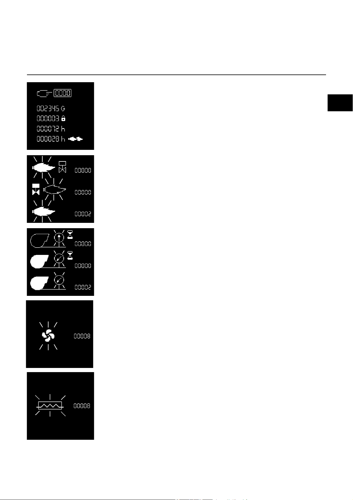
Operating statistics menu
To access the statistics menu, press any key when the burner is ready to operate, already
operating, or malfunctioning. It is not possible to access the statistics menu during the start-up
phase.
The general menu screen will appear. Using the , , , or keys, place the cursor on the
statistics menu symbol, and confirm using the key.
The statistical data menu comprises 7 screens. You can navigate between the different screens
using the and keys.
- Flame detection time for last burner start-up
- Average flame detection time for the last 5 burner start-ups
- Total number of burner start-ups
- Total number of faults
- Total number of operating hours
- Total number of operating hours in 2nd stage
02/2016 - Art. Nr. 4200 1046 8202A28
Page 29
en
Servicing
Operating statistics menu
- Total number of burner start-ups since the last meter reset
- Number of faults since the last meter reset
- Total operating time since the last meter reset
- Operating time in 2nd stage since the last meter reset
- Number of "Unauthorised flame" faults
- Number of "No flame after safety time" faults
- Number of "Flame extinguishing during operation" faults
- Number of "Air pressure switch stuck" faults
- Number of "Air pressure switch does not close during operation" faults
- Number of "Air pressure switch switching over" faults
- Number of "Fan motor" faults
- Number of "Heater" faults
02/2016 - Art. Nr. 4200 1046 8202A 29
Page 30

02/2016 - Art. Nr. 4200 1046 8202A30
Page 31

en
02/2016 - Art. Nr. 4200 1046 8202A 31
Page 32

www.elco.net
Made in EU.
Non contractual document.
02/2016 - Art. Nr. 4200 1046 8202A32
 Loading...