

elco VARION C-POWER 30.0, VARION C-POWER 7.2, VARION C-POWER 25.0, VARION C-POWER 20.0, VARION C-POWER 11.0 Operation Manual
...Page 1
Operation manual
Combined heat and power unit
VARION® C-POWER S, M, M+
06.2019
Made in Germany
Page 2

Contents
1. Document information. . . . . . . . . . . . . . . . . . . . . . . . 4
1.1 Validity. . . . . . . . . . . . . . . . . . . . . . . . . . 4
1.2 Supporting documents. . . . . . . . . . . . . . . . . 4
1.3 Safety instructions . . . . . . . . . . . . . . . . . . . 5
1.4 Explanation of symbols . . . . . . . . . . . . . . . . 5
2. Safety information ...........................6
2.1 Intended use . . . . . . . . . . . . . . . . . . . . . . 6
2.2 Authorised target groups . . . . . . . . . . . . . . . 6
2.2.1 Manufacturer ........................ 6
2.2.2 Operator ............................ 6
2.2.3 Trained personnel .................... 6
2.2.4 User ............................... 6
2.3 General safety instructions . . . . . . . . . . . . . . 7
3. Product information ..........................8
3.1 Functional principle . . . . . . . . . . . . . . . . . . 8
3.2 Registering with the energy provider . . . . . . . . . 8
3.3 Modes of operation . . . . . . . . . . . . . . . . . . 8
3.3.1 Ready for e-car charging button ........ 8
3.3.2 Summer operation ................... 8
3.3.3 Heat-optimised ...................... 8
3.3.4 Electricity-optimised .................. 8
3.3.5 Shutdown ........................... 8
3.4 Safety devices. . . . . . . . . . . . . . . . . . . . . . 9
3.5 Product variants . . . . . . . . . . . . . . . . . . . . 9
3.5.1 VARION® C-POWER S ................. 9
3.5.2 VARION® C-POWER M. . . . . . . . . . . . . . . . . 9
3.5.3 VARION® C-POWER M+ ............... 9
3.6 Product overview. . . . . . . . . . . . . . . . . . . 10
3.6.1 Generation unit ..................... 10
3.6.2 Control cabinet ..................... 10
3.6.3 Modem ............................ 10
3.6.4 Expansion tank connection block ...... 11
3.6.5 MSM adapter magnetic filter (“MSM
filter”) ............................. 11
3.7 Scope of supply . . . . . . . . . . . . . . . . . . . . 11
4. Storage ...................................12
5. Assembly ..................................13
5.1 Safety instructions for assembly . . . . . . . . . . 13
5.2 Installation location requirements . . . . . . . . . 13
5.2.1 Overview of the installation location ... 13
5.2.2 Premises ........................... 14
5.2.3 Heating system ..................... 15
5.2.4 Flue ............................... 15
5.2.5 Exhaust air duct ..................... 15
5.2.6 Supply air supply .................... 15
5.2.7 Gas supply ......................... 15
5.2.8 Water supply ....................... 16
5.2.9 Condensate drain ................... 16
5.2.10 Power supply ....................... 16
5.2.11 Reactive current compensation ........ 16
5.2.12 Mobile communications network ...... 16
5.3 Assembly steps . . . . . . . . . . . . . . . . . . . . 17
5.3.1 Preparing for assembly ............... 17
5.3.2 Unpacking the system ................ 17
5.3.3 Positioning the generation unit ........ 18
5.3.4 Screwing the control cabinet in position 19
5.3.5 Screwing the expansion tank
connection block in position 19
5.3.6 Connecting the generation unit ........ 19
5.3.7 Connecting the temperature sensors ... 23
5.3.8 Connecting the modem .............. 23
5.3.9 Connecting the control cabinet ........ 24
5.3.10 Checking the connections ............ 24
5.4 Test run . . . . . . . . . . . . . . . . . . . . . . . . 25
5.4.1 Opening the generation unit .......... 25
5.4.2 Preparing the expansion tank
connection block .................... 26
5.4.3 Replenishing the cooling water ........ 26
5.4.4 Starting the test run ................. 27
5.4.5 Checking the system ................. 27
5.4.6 Stopping the test run ................ 28
5.4.7 Closing the generation unit ........... 28
6. Commissioning .............................29
7. Operation .................................30
8. Cleaning ...................................31
9. Service repairs .............................32
9.1 Maintenance . . . . . . . . . . . . . . . . . . . . . 32
9.2 Fault resolution . . . . . . . . . . . . . . . . . . . . 32
9.3 Repair . . . . . . . . . . . . . . . . . . . . . . . . . 33
10. Disassembly ...............................34
11. Disposal ...................................35
11.1 Disposing of packaging. . . . . . . . . . . . . . . . 35
11.2 Disposing of the system . . . . . . . . . . . . . . . 35
2
Operation manual VARION® C-POWER – S, M, M+ / 06.2019
Page 3

12. Appendix ..................................36
12.1 Hydraulic diagrams . . . . . . . . . . . . . . . . . . 36
12.1.1 Heating system variant 1 –
1 VARION® C-POWER, 1 buffer tank,
peak load boiler connected directly to
buffer tank ......................... 37
12.1.2 Heating system variant 2 –
1 VARION® C-POWER, 2 buffer tanks,
peak load boiler connected directly to
buffer tank ......................... 38
12.1.3 Heating system variant 3 –
1 VARION® C-POWER, 1 buffer tank,
peak load boiler connected to buffer
tank via hydraulic separator ........... 39
12.1.4 Heating system variant 4 –
1 VARION® C-POWER, 2 buffer tanks,
peak load boiler connected to buffer
tank via hydraulic separator ........... 40
12.1.5 Heating system variant 5 –
2 VARION® C-POWER, 2 buffer tanks,
peak load boiler connected to buffer
tank via hydraulic separator ...........
12.2 Energy label . . . . . . . . . . . . . . . . . . . . . . 42
12.2.1
12.2.2 VARION® C-POWER M. . . . . . . . . . . . . . . . 42
12.2.3
12.3 EC declaration of conformity .
VARION® C-POWER S ................
VARION® C-POWER M+ ..............
. . . . . . . . . . .
41
42
42
43
Operation manual VARION® C-POWER – S, M, M+ / 06.2019
3
Page 4

Document informaon
i
1. Document information
1.1 Validity
Original operation manual.
This manual is valid for the following products and
performance categories:
B VARION® C-POWER S
B VARION® C-POWER 5.0
B VARION® C-POWER 7.2
B VARION® C-POWER M
B VARION® C-POWER 11.0
B VARION® C-POWER 16.0
B VARION® C-POWER 20.0
B VARION® C-POWER M+
B VARION® C-POWER 25.0
B VARION® C-POWER 30.0
1.2 Supporting documents
i
Additional documents belong to this operation manual and
must be observed.
“ELCO/Control” operation manual
The “ELCO/Control” operation manual describes how
to control the system via the operational display and is
included in the scope of delivery.
Wiring diagrams
The wiring diagrams are located on the inside of the control
cabinet door.
Technical data
The document for technical data is included in the scope of
delivery.
Manuals for system components
The manuals for the supplied system components (e.g. MSM
filter, modem) are included in the scope of delivery.
Manuals for accessories
The manuals for optional accessories (e.g. flue gas silencer,
exhaust air kit) are provided with each product.
This document is valid for all products with a serial number
starting with “ID 2000” onwards.
The descriptions are identical for all products; any
differences are specifically highlighted.
All illustrations show the product “VARION® C-POWER S”.
In this manual, the word “system” is used to denote the
product.
This manual is protected by copyright law. Duplication,
reproduction and transmission is only permitted with the
permission of the manufacturer.
Subject to change without notice.
Maintenance manual
The maintenance manual describes specific tasks for
maintaining the system that must only be performed by the
manufacturer. The maintenance manual is not included in
the scope of delivery.
Forms
Various forms for exchanging information (e.g. commissioning
request, datasheet for the generation system) are included
with the delivery.
4
Operation manual VARION® C-POWER – S, M, M+ / 06.2019
Page 5
Document informaon
i
1.3 Safety instructions
D DANGER!
Information highlighted with the word HAZARD warns
against a hazardous situation that will lead to death or
severe injury.
D WARNING!
Information highlighted with the word WARNING warns
against a hazardous situation that can lead to death or
severe injury.
D CAUTION!
Information highlighted with the word CAUTION warns
against a situation that can lead to minor or moderate
injuries.
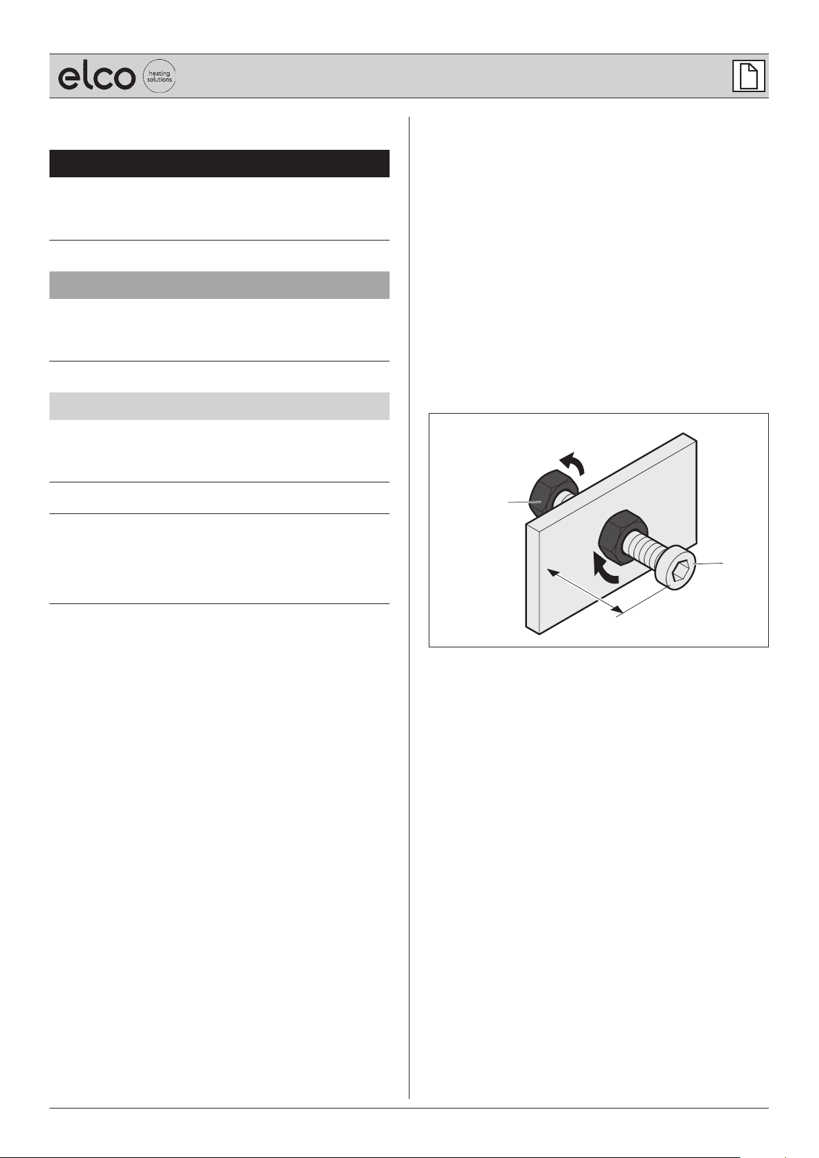
1.4 Explanation of symbols
Text
A Required action
B List
Cross reference to another point in this document
D
Cross reference to other documents that must be
observed
Internet link
Ј
Illustrations
2.
B
D ATTENTION!
Information highlighted with the word ATTENTION
warns against a situation that can lead to material or
environmental damage.
1.
x
1. Numbered action sequence
A Part designations with upper case letters
x Dimensions with lower case letters or units in mm
Arrows indicating movement and direction
A
Operation manual VARION® C-POWER – S, M, M+ / 06.2019
5
Page 6
Safety informaon
2. Safety information
2.1 Intended use
The system is a combined heat and power unit for
generating electricity and heat. The system is intended
exclusively for incorporation in heating circuits in buildings.
The system is designed for bivalent operation, i.e. it must
be combined with an additional heat source (“peak load
boiler”) in order to operate.
The system is designed for the following energy demand.
System Annual energy requirement
Electricity kWh Heat kWh
VARION®
C-POWER S
VARION®
C-POWER M
VARION®
C-POWER M+
The system is only permitted for use in a technically
sound condition once it has been commissioned by the
manufacturer or a specialist partner authorised by the
manufacturer.
Intended use also includes reading and following this
manual.
20,000 - 50,000 60,000 - 100,000
80,000 - 130,000 180,000 - 300,000
100,000 - 250,000 200,000 - 400,000
2.2.2 Operator
The operator is responsible for the building in which the
product is installed. The operator has the following duties:
B Fulfilling the requirements specified by the energy
provider (e.g. registration, approval, compensation).
B Meeting the installation location requirements.
B Training the user.
B Complying with statutory occupational health and safety
obligations.
B Complying with the valid safety, accident prevention and
environmental protection regulations.
B Providing and complying with the documentation.
B Ensuring that the product is always kept in a technically
sound condition.
B Storing the system when necessary.
2.2.3 Trained personnel
Trained personnel are responsible for the assembly,
maintenance, disassembly and disposal of the product.
The following points must be observed:
B All tasks must only be performed by qualified personnel
who have been trained by the manufacturer and who
are familiar with assembly technology, gas and water
installations, and current safety regulations.
B Special installation tasks (e.g. tasks involving the
building structure or the ventilation system) must only
be performed by the suitably qualified personnel of
specialist companies.
B Electrical installations must only be performed by
qualified, skilled electricians.
Only qualified personnel trained by the manufacturer have
access to the “Specialist” area of the “ELCO/Control” control
mechanism.
Any other use is considered contrary to intended use.
2.2 Authorised target groups
This manual is intended for various target groups that are
authorised for specific duties.
2.2.1 Manufacturer
The manufacturer, ELCO GmbH, supplies the product and
has the following duties:
B Training experts on assembly, maintenance, disassembly
and disposal.
B Commissioning the system.
Only the manufacturer has access to the “Experts” area of
the “ELCO/Control” control mechanism.
6
2.2.4 User
Users may perform operational and cleaning tasks on this
product. Obligations of the user:
B To be trained on the product by the operator.
B To be familiar with this manual.
Trained users have access to the non-protected areas of the
“ELCO/Control” control mechanism, but not to the “Experts”
and “Specialist” areas.
Operation manual VARION® C-POWER – S, M, M+ / 06.2019
Page 7

Safety informaon
2.3 General safety instructions
D WARNING!
Hazard caused by failing to observe the manual.
This manual contains important information for handling the
system safely. Potential hazards are specifically highlighted.
Failing to observe such information can lead to death or
severe injuries.
A Read the manual carefully.
A Follow the safety instructions contained in this manual.
A Follow the safety instructions on the system
A Store the manual in an accessible place.
If you can smell gas, immediately proceed as follows:
B Close the gas valve.
B Do not generate any naked flames.
B Do not operate any electrical switches
(e.g. light switches, all-pole separating points).
B Do not use any electrical appliances in the
hazardous area (e.g. telephone).
B Ventilate the rooms.
B Inform the manufacturer, gas utility company or qualified
service company.
The manufacturer does not accept any liability or guarantee
for damage or loss in the following cases:
B Failing to observe this manual.
B Contrary-to-intended use.
B Improper handling.
B Use by unauthorised target groups.
B Failing to meet the installation location requirements.
B Using replacement parts that have not been authorised
by the manufacturer.
B Bypassing the system’s safety devices.
B Removing the system’s seals and sealants.
B Failing to comply with the maintenance intervals.
Additional safety instructions are provided in the respective
chapters of this manual.
“4. Storage” (page 12).
D
“5. Assembly” (page 13).
D
“6. Commissioning” (page 29).
D
“7. Operation” (page 30).
D
“8. Cleaning” (page 31).
D
“9. Service repairs” (page 32).
D
“10. Disassembly” (page 34).
D
“11. Disposal” (page 35).
D
Use of the system is prohibited in the following cases:
B If the system or individual components are damaged.
B If the system has been altered or modified without
authorisation.
B If the supply and return lines (e.g. gas, flue gas, water,
electricity, condensate drain) are altered or modified
without authorisation.
B If any safety devices are missing or inoperable.
“3.4 Safety devices” (page 9).
D
B During the construction phase of the building.
B If the system has been in storage for more than
16 weeks after delivery.
“9. Service repairs” (page 32).
D
B If the system has been decommissioned for more than
16 weeks.
B For children or individuals who are incapable of
assessing the hazards associated with operating the
system.
Operation manual VARION® C-POWER – S, M, M+ / 06.2019
7
Page 8

Product informaon
3. Product information
3.1 Functional principle
The combustion of gas powers a high-performance
alternator that produces electricity.
The heat that is generated by this process is used for hot
water provision and heating.
This principle is referred to as combined-heat-and-power.
3.3 Modes of operation
The system can be operated in five modes of operation
(including shutdown). The modes of operation are set via
the operational display.
“ELCO/Control” operation manual.
3.3.1 Ready for e-car charging button
Special mode for charging electric
to produce electricity in this mode if the storage battery is
fully charged.
3.3.2 Summer operation
In summer operation mode, the system only operates at
minimum capacity. The system only starts if the storage
battery has insufficient charge.
3.3.3 Heat-optimised
The system starts if a temperature requirement has been
set. If the storage battery has reached a specific percentage
charge, the system begins to power down steplessly.
vehicles. It is still possible
The control mechanism manages and monitors the
combustion process in the generation unit. The system is
operated via the operational display on the control cabinet.
3.2 Registering with the energy provider
The energy provider must be informed about the installation
of the system. Obligations of the operator:
A Inform the energy provider about the system before it is
assembled.
A Fulfil the requirements specified by the energy provider
(e.g. registration, approval, compensation).
A Provide the energy provider with all the relevant system
data.
Technical data.
The electricity produced over and above the operator’s own
requirement can be fed into the energy provider’s local
electricity network in return for compensation. A suitable
application must be submitted to the energy provider for
this purpose.
3.3.4 Electricity-optimised
The system starts to operate according to a temperature
requirement. Once a specific storage battery charge has
been reached, the system aligns itself to the electricity
consumption of the building.
3.3.5 Shutdown
The system is in hibernation mode. The system does not
start according to temperature requirements.
8
Operation manual VARION® C-POWER – S, M, M+ / 06.2019
Page 9
Product informaon
3.4 Safety devices
D WARNING!
Risk of burns, pinching or electric shock.
The safety devices are intended to ensure the system is
handled safely. Missing or faulty safety devices can lead to
hazardous situations.
A Ensure that the protection devices are not removed.
A Follow the safety instructions on the system.
A Only remove the covers if you are required and
authorised to do so.
The system is equipped with the following safety devices:
B Emergency stop switch
B Pressure-relief valve
B Protective covers
B Safety stickers
3.5 Product variants
3.5.1 VARION® C-POWER S
3.5.2 VARION® C-POWER M
B VARION® C-POWER 11.0
B VARION® C-POWER 16.0
B VARION® C-POWER 20.0
B VARION® C-POWER 5.0
B VARION® C-POWER 7.2
3.5.3 VARION® C-POWER M+
B VARION® C-POWER 25.0
B VARION® C-POWER 30.0
Operation manual VARION® C-POWER – S, M, M+ / 06.2019
9
Page 10
Product informaon
3.6 Product overview
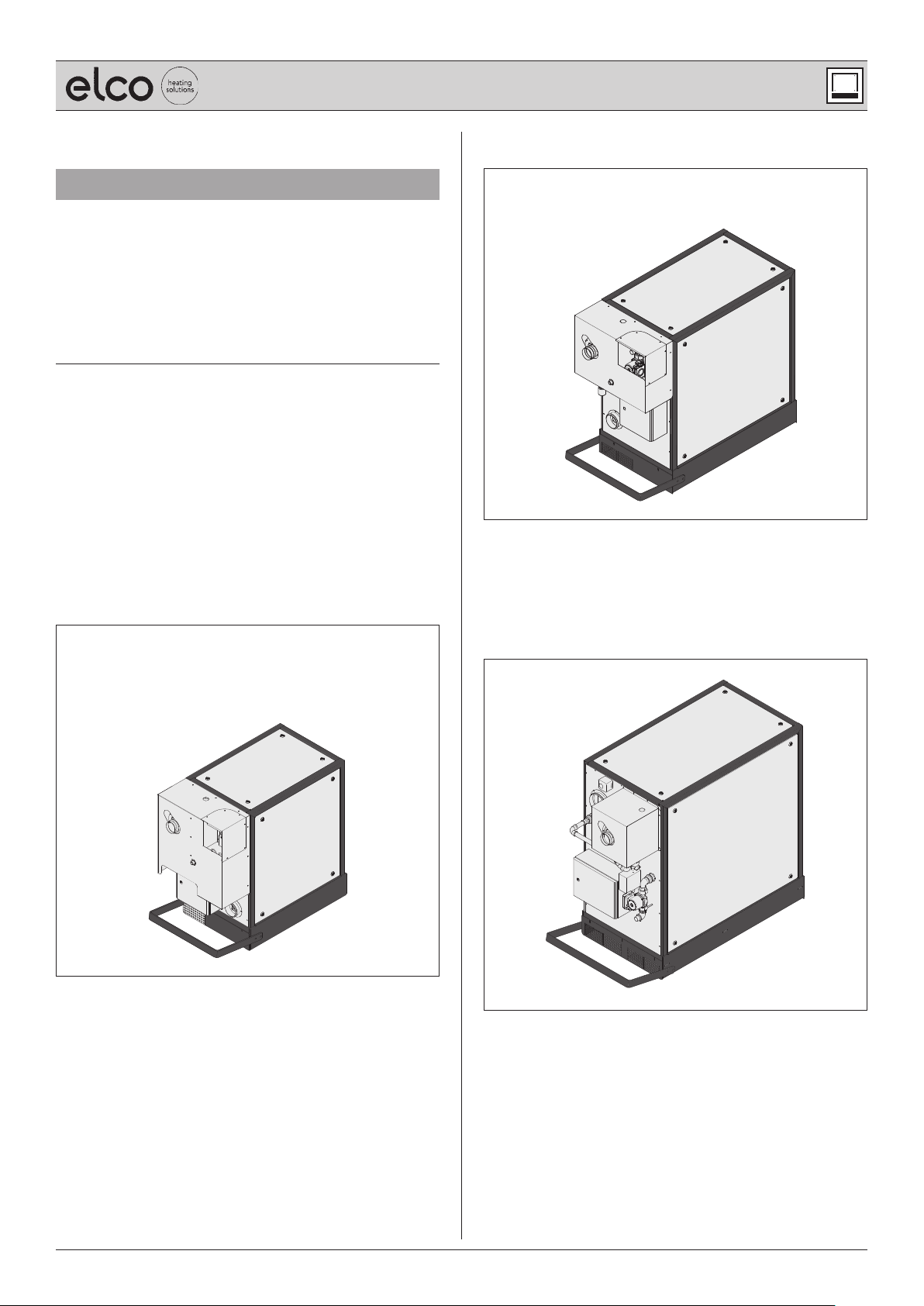
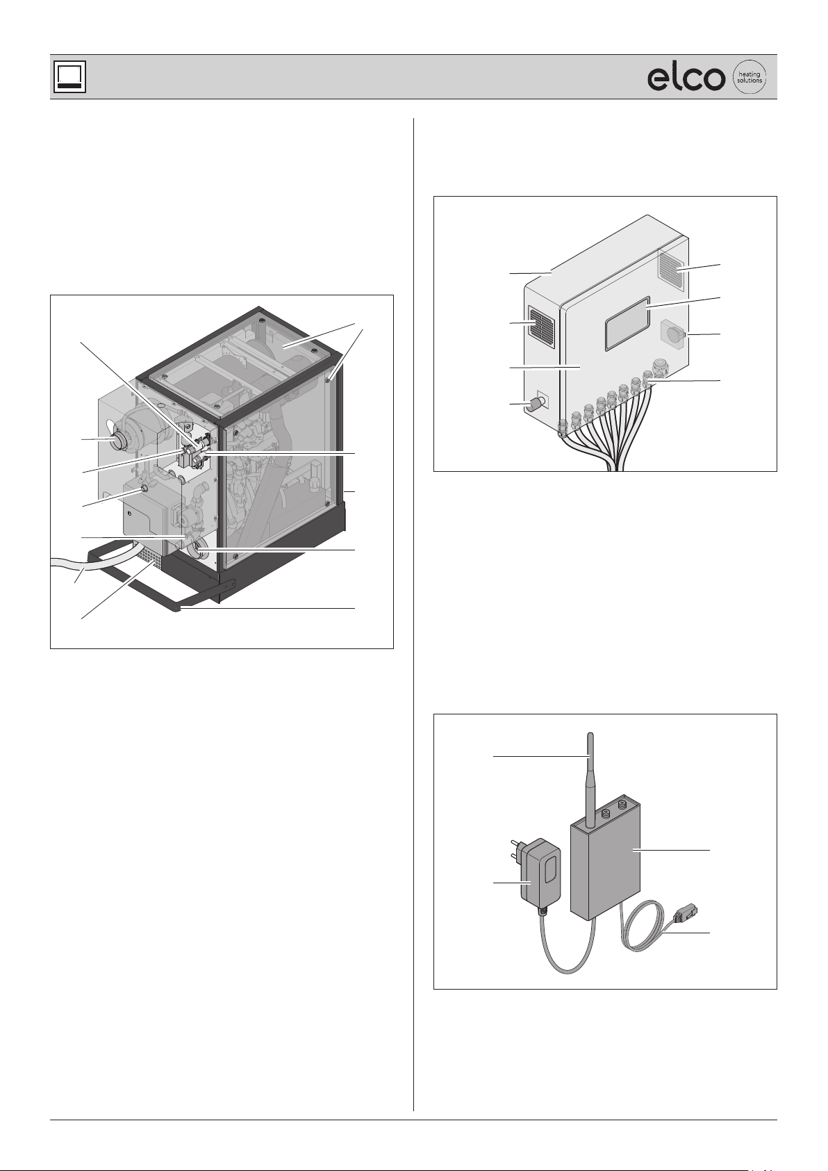
3.6.1 Generation unit
The generation unit contains the actual combined heat and
power unit with the combustion engine, the alternator unit
and the heat exchangers.
The generation unit is the core piece of equipment for
producing the electricity and heat.
H
A
B
I
C
J
D
E
K
F
G
L
3.6.2 Control cabinet
The control cabinet contains all the components required to
control the system.
A
B
E
B
F
C
G
D
A Housing
B Aeration and ventilation
C Control cabinet door
D Emergency stop switch
E Operational display
F Master switch
G Cable bushings
3.6.3 Modem
A “Buffer water supply line” connection
B “Flue gas” connection
C “Gas” connection
D “Condensate” connection
E “Buffer water return line” connection
F Control cabinet wiring harness
G Supply air intake grille
H Housing cover
I Expansion tank connection
J Type plate
K “Exhaust air” connection (room-air dependent)
L Hoop guard
The modem makes it possible to monitor the system
remotely and read data via the mobile communications
network.
A
C
B
D
A Antenna (slot “GSM Main”)
B Power supply
C GSM modem
D Connection cable (slot “LAN 1”)
10
Operation manual VARION® C-POWER – S, M, M+ / 06.2019
Page 11
Product informaon
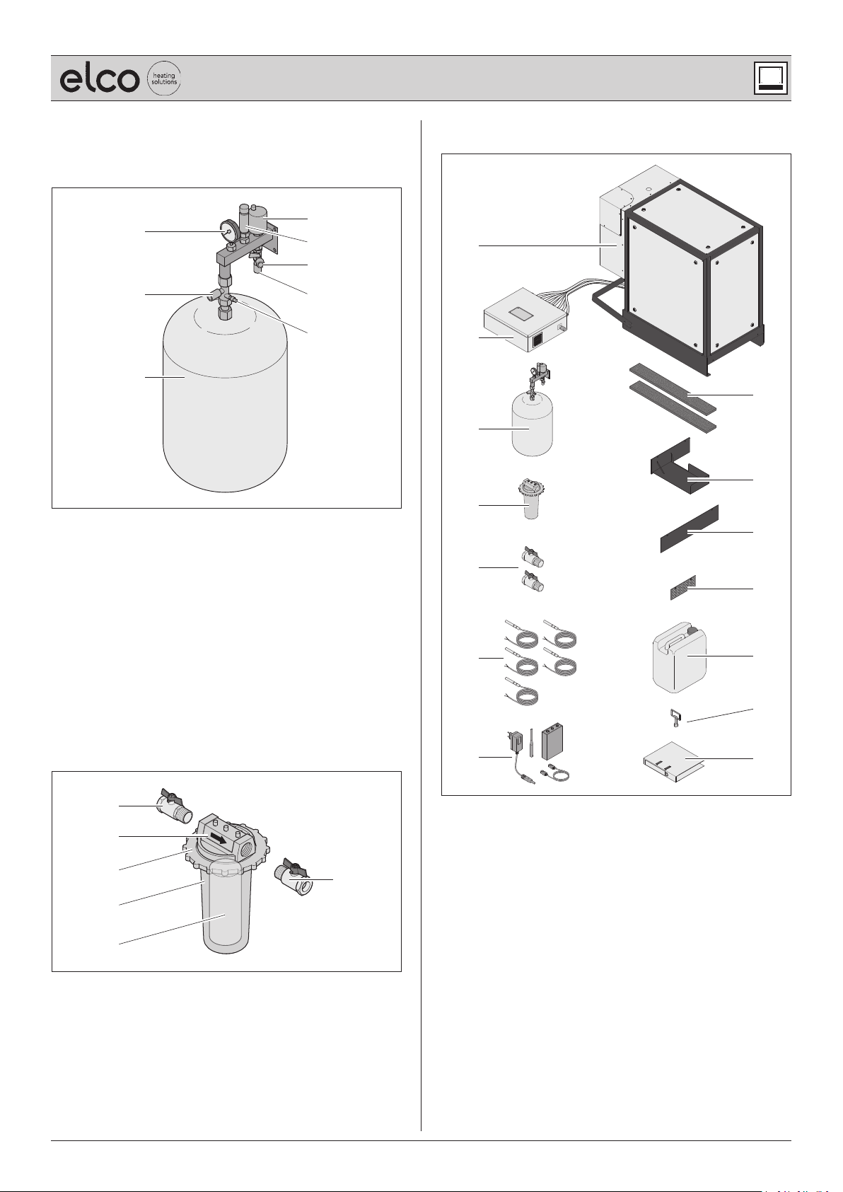
3.6.4 Expansion tank connection block
The expansion tank offsets temperature-related fluctuations
in volume within the motor circuit (primary circuit).
D
A
E
F
B
G
H
C
A Manometer
B Cap valve
C Expansion tank
D Self-bleeding device
E Pressure-relief valve
F Fill-and-drain valve (connection for replenishing "water-
glycol mixture 60:40")
G Connection to generation unit
H Drain valve
3.7 Scope of supply
A
B
C
D
E
F
H
I
J
K
L
3.6.5 MSM adapter magnetic filter (“MSM filter”)
The combination filter filters magnetite and suspended
solids out of the water in the heating system.
A
B
C
A
D
E
A Valve
B Filter head (with indication of the direction of flow)
C Lock nut
D Brass cup
E Filter cartridge
M
G
A Generation unit
B Control cabinet
C Expansion tank connection block
D MSM filter
E Valve
F Temperature sensor
G Modem
H Balance strips
I Rear cover
J Front cover
K Supply air intake grille
L Cooling medium ("water-glycol mixture 60:40")
M Square spanner
N Documentation (e.g. operation manual)
1
Includes 24 months of remote monitoring (effective from
commissioning; extension available subject to charge)
1
N
Operation manual VARION® C-POWER – S, M, M+ / 06.2019
11
Page 12
Storage
4. Storage
The system is prepared by the manufacturer for operation
on delivery. The system must be put into operation within
16 weeks following delivery. If that is not possible, the
system must be put into storage.
Storage of the system by the operator.
“2.2.2 Operator” (page 6).
D
D ATTENTION!
Risk of damage caused by improper storage.
During long periods of downtime, lubricants and liquids
settle within the system. Frost and damp conditions can
damage parts of the system.
A Store the system in a frost-free, dry place.
A Arrange for the manufacturer to rust-proof the system if
it is to be kept out of operation for more than 16 weeks.
When taking the system out of storage, the next steps must
be discussed with the manufacturer.
A Contact the manufacturer.
12
Operation manual VARION® C-POWER – S, M, M+ / 06.2019
Page 13
Assembly
5. Assembly
5.1 Safety instructions for assembly
D WARNING!
Hazard caused by failing to observe the assembly
instructions.
Errors made when installing the system can cause serious
injuries or material damage to the system or the building.
This chapter contains important information regarding the
safe assembly of the system.
A Read this chapter carefully before assembling the
system.
A Follow the safety instructions.
A Carry out the assembly as described.
The assembly must only be performed by trained
personnel.
Electrical work must only be performed by qualified, skilled
electricians.
“2.2.3 Trained personnel” (page 6).
D
B The system must be undamaged and in a faultless
condition before assembly.
B Only use suitable fittings.
B Cables and lines must not be damaged, kinked or
crimped.
B Before assembling, ensure that the supply voltage has
been and remains disconnected.
The supply voltage is only reconnected when instructed
in the respective assembly step.
B The generation unit must be transported to
the installation location by means of a suitable
transportation device (e.g. lift truck).
If it is not possible to transport it to the installation
location (e.g. lack of space):
A Contact the manufacturer.
5.2 Installation location requirements
D WARNING!
Risk of suffocation, gas explosions or material damage
caused by incorrectly installing the system.
Failing to observe these requirements can lead to hazardous
situations when handling electricity or gas. This chapter
contains important information for preventing hazardous
situations.
A Ensure that all of the installation location requirements
are complied with.
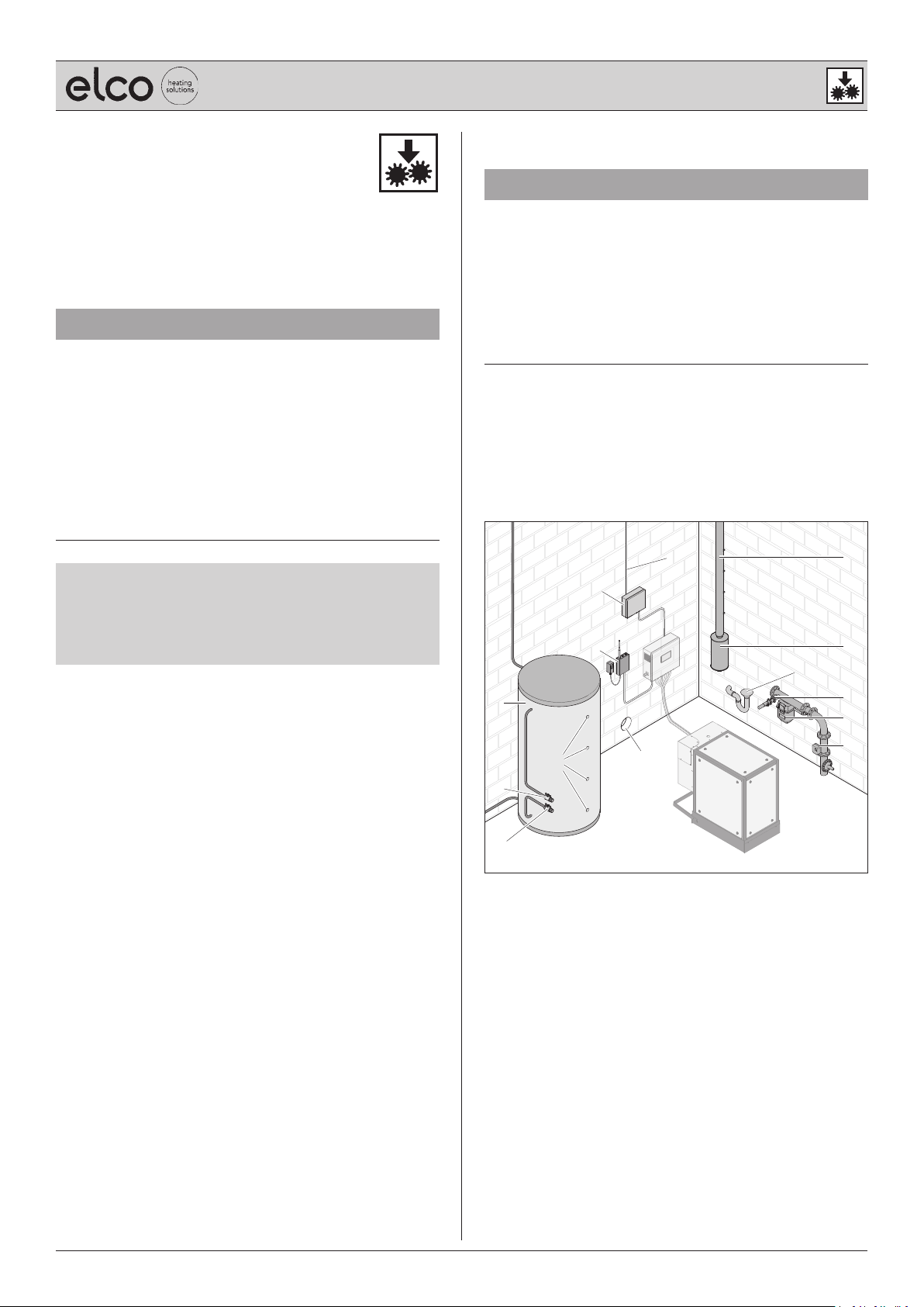
5.2.1 Overview of the installation location
To operate the system, some equipment must be provided
on site. The following illustration shows examples of the
required components.
H
E
F
A
B
G
C
D
A Buffer tank
B Temperature sensor holding fixture
A Buffer water supply line
E Buffer water return line
E Reactive current compensation
F Modem
G Supply air opening
H Supply voltage
I Flue
J Flue gas silencer
K Condensate drain
L Gas supply
M Gas meter
N Gas flow monitor
K
I
J
L
M
N
Operation manual VARION® C-POWER – S, M, M+ / 06.2019
The heating system also includes the peak load boiler and
pipework system that connects the system via the buffer
tank.
13
Page 14
Assembly
5.2.2 Premises
The premises must meet the following requirements:
B The installation location must comply with the effective
applicable laws and regulations for boiler rooms
(e.g. in Germany, the ordinance for heat-producing
appliances (Feuerstättenverordnung)).
B The substrate on which the generation unit is to be
installed must be flat, even, solid, dry and load-bearing.
B The ambient air temperature must be between
+5°C and +30°C.
B The system must be protected against frost and the
elements.
The following are not permitted:
B Installation on floating screed.
B Operation of tumble dryers in the same room.
B Storage of explosive or highly flammable materials
(e.g. paper, paints, petrol) within the installation
location.
B Use of aggressive substances (e.g. sprays, solvents,
chlorinated cleaning agents, paints, adhesives) in the
vicinity of the system.
If the system is installed in vaulted cellars or bare smoothwalled rooms (hard-walled), there is a risk of noise and
sound resonance.
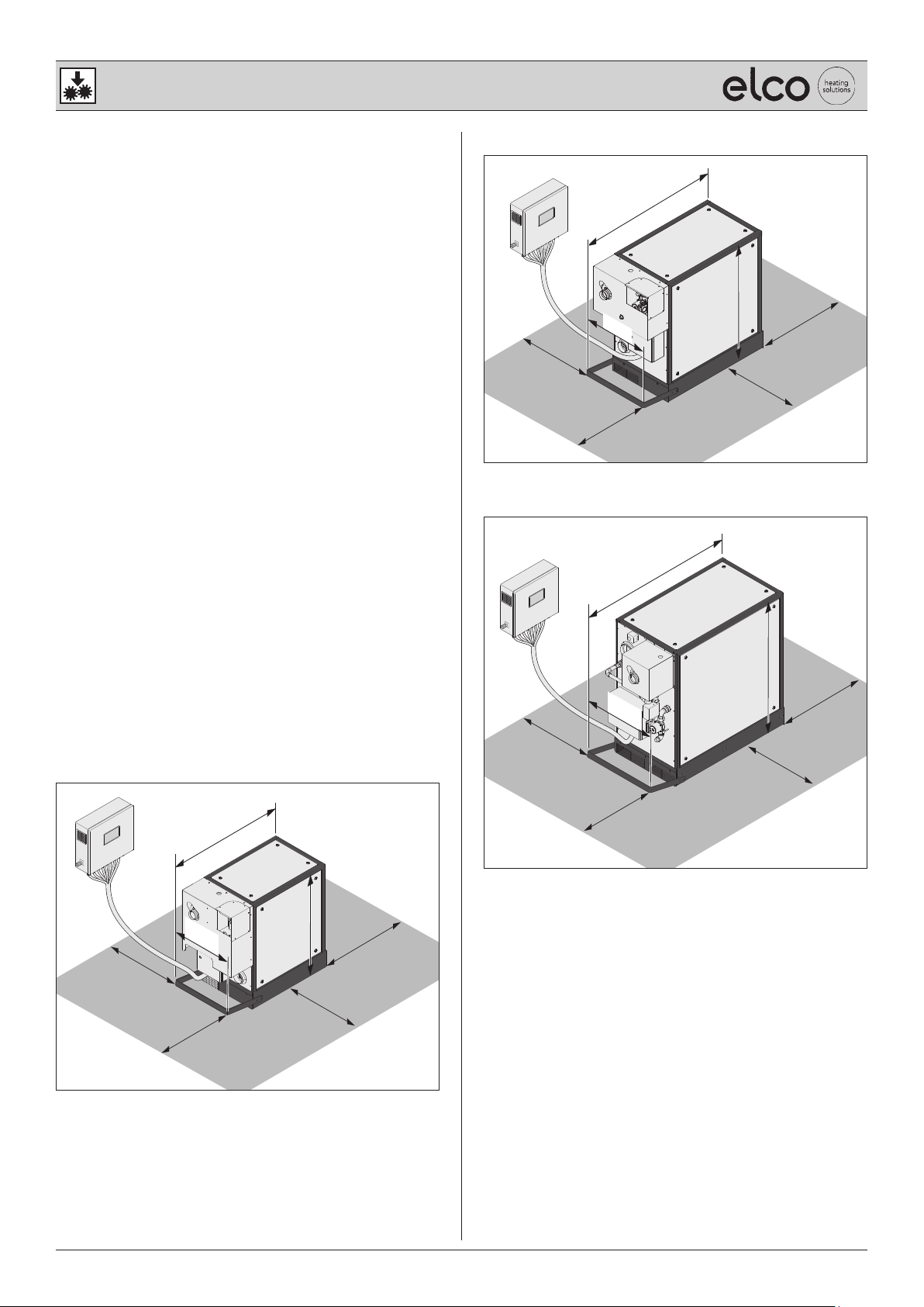
Space requirement for VARION® C-POWER M
1480
643
708
> 1000
> 1000
1097
1233
> 1000
Space requirement for VARION® C-POWER M+
1659
> 1000
The system must be positioned so that the following
requirements are fulfilled:
B None of the system’s ventilation or extraction devices
may be blocked or closed.
B The emergency stop switch must always be accessible.
Space requirement for VARION® C-POWER S
1226
635
> 1000
> 1000
1097
> 1000
> 1000
1400
> 1000
781
> 1000
> 1000
> 1000
The minimum clearance to the generation unit (> 1,000 mm
on all sides) must be maintained.
14
Operation manual VARION® C-POWER – S, M, M+ / 06.2019
Page 15

Assembly
5.2.3 Heating system
The structural elements of the building’s heating system
primarily comprise the peak load boiler, the buffer tank,
and the pipework system and radiators.
The peak load boiler supplies the required residual heat if
the heating energy requirement exceeds the capacity of the
system (e.g. in extremely cold weather).
The buffer tank acts as a hydraulic separator and isolates the
system from the building’s heating system.
For the system to operate, a buffer tank is required, which
must comply with the following requirements:
B The buffer tank must have holding fixtures for the
temperature sensors.
B The buffer tank must have shut-off devices fitted on the
connections to the system.
B The buffer tank must be designed to meet the system
specifications.
B Minimum 100 litres per kW thermal
for installations < 10 kW
B Minimum 50 litres per kW thermal
for installations > 10 kW
th
th
5.2.5 Exhaust air duct
D WARNING!
Risk of suffocation due to improper use of exhaust air.
The exhaust air must not be used for heating purposes.
Poisonous gases may be produced inside the generation unit
that can lead to death by suffocation.
A Ensure that the exhaust air from the generation unit is
guided outside.
A Ensure that the supply air is not contaminated by the
exhaust air.
An accessory is required (optionally available) if exhaust air
and flue gas are extracted together:
B Exhaust air kit if extracting from one system.
B Backflow preventer if extracting in combination with
another heat source (peak load boiler or another
system).
Additional devices with exhaust air (e.g. washer-dryers)
may only be installed subject to consultation with a suitable
specialist or chimney sweep.
These specifications are technical minimum conditions.
Regional or national funding guidelines (e.g. in accordance
with BAFA in Germany) may differ and must be checked.
The dimensioning of the pipework system must be designed
to meet the following requirements:
B Maximum heat requirement of the building.
B Maximum thermal capacity of the system.
5.2.4 Flue
For the system to operate, the building must have a flue,
which must comply with the following requirements:
B The local laws and regulations must be complied with
(e.g. in Germany, the building regulations).
B The flue gas routing must comply with the local
regulations (e.g. in Germany, DIN 18160).
B The flue gases must be removed via a flue.
B As a fundamental rule, the flue must extract the flue
gases via the roof.
B The dimensions for the exhaust gas ducting and flue
must be calculated on an individual basis.
B The gradient of the horizontal section must be min. 5 cm
per metre.
B The flue must be inspected and approved for operation
(e.g. by a master chimney sweep).
B A flue gas silencer must be fitted in the flue gas routing.
The flue gas silencer (optionally available) must be
installed near the generation unit.
B The flue gas routing must have a water-filled siphon at
its lowest point.
5.2.6 Supply air supply
Sufficient supply air must be supplied for the combustion
process and the ambient temperature:
B The total requirement of the heating system (e.g. for the
peak load boiler) must be born in mind.
B The supply air supply must meet the system
specification.
Technical data.
5.2.7 Gas supply
For the system to operate, a gas supply is required that must
comply with the following requirements:
B The gas supply must comply with the established
regulations (e.g. in Germany, TRGI).
B The system specifications (e.g. type and composition of
the gas) must be complied with.
Technical data.
B The building’s system must be fitted with a gas flow
monitor and a gas meter.
B The gas flow monitor must meet the system
specifications.
Technical data.
B Connection via a gas appliance outlet is never permitted.
An accessory is required (optionally available) if exhaust air
and flue gas are extracted together:
B Exhaust air kit if extracting from one system.
B Backflow preventer if extracting in combination with
another heat source (peak load boiler or another
system).
Operation manual VARION® C-POWER – S, M, M+ / 06.2019
15
Page 16

Assembly
5.2.8 Water supply
D ATTENTION!
Risk of damage caused by poor water quality.
Too high a proportion of suspended solids and magnetite
along with the incorrect water hardness can damage the
generation unit or shorten its service life.
A Check the water quality regularly.
A Use the MSM filter.
B The water quality must comply with the specifications of
the applicable standards and Directives
(e.g. in Germany, VDI Regulation 2035).
B The heating system water must be free from mechanical
impurities.
B The hardness of the water must be < 0.11 °dH.
B Conductivity < 100 µS/cm.
B PH value > 8.2 and < 9.0.
5.2.9 Condensate drain
For the system to operate, the building must have a
condensate drain, which must comply with the following
requirements:
B The condensate drain must be depressurised.
B The local water disposal regulations must be considered.
B The siphon must be constructed from a corrosion- and
acid-resistant material (e.g. plastic or stainless steel).
B The drain’s siphon must remain filled with water even
during an interruption to operation.
5.2.12 Mobile communications network
Remote monitoring via the modem requires access to the
mobile communications network. The modem must be
accessible. The position of the modem has an influence on
the reception quality.
The reception quality may be improved as required by
means of the following accessory (optionally available):
B External antenna
B Patch cable (max. 100 m)
5.2.10 Power supply
For the system to operate, the building requires a
connection to the electricity supply that must comply with
the following requirements:
B The specifications and technical connection conditions
of the energy provider must be taken into consideration
(e.g. electricity meter).
B The start-up power and cable lengths must be taken into
account when calculating the cable cross-sections.
B The supply voltage must meet the system specifications.
Technical data.
5.2.11 Reactive current compensation
For the system to operate, the energy provider stipulates
the need for reactive current compensation.
The reactive current compensation reduces the reactive
current generated by the system and thus relieves the
supply network. The reactive current compensation must
meet the system specifications.
Technical data.
16
Operation manual VARION® C-POWER – S, M, M+ / 06.2019
Page 17

Assembly
5.3 Assembly steps
Brief overview:
5.3.1 Preparing for assembly
5.3.2 Unpacking the system
5.3.3 Positioning the generation unit
5.3.4 Screwing the control cabinet in position
5.3.5 Screwing the expansion tank connection block in
position
5.3.6 Connecting the generation unit
5.3.7 Connecting the temperature sensors
5.3.8 Connecting the modem
5.3.9 Connecting the control cabinet
5.3.10 Checking the connections
5.3.1 Preparing for assembly
A Familiarise yourself with the assembly situation and the
documentation.
B System
B System components
B Safety devices
B Accessories
B Installation location
B Operation manual and supporting documents
A Gather together the required tools and materials.
A Keep the assembly area clear of objects than may get in
the way or be damaged.
A Check that all of the installation location requirements
have been fulfilled.
“5.2 Installation location requirements” (page 13).
D
A Ensure that the supply voltage has been and remains
disconnected. Only connect the supply voltage when
instructed in the respective assembly step.
5.3.2 Unpacking the system
D ATTENTION!
Risk of damage caused by improper handling.
The system may be damaged during unpacking or
transportation.
A Do not cut through the protective packaging.
A Keep objects that might damage the system away from it
(e.g. tools).
A Remove the packaging material from the system.
A Remove the parts included in the scope of delivery from
on top of the generation unit.
A Check the system and all the parts it contains for
damage.
A Check the scope of delivery according to the delivery
note for completeness.
If parts are missing or damaged:
A Contact the manufacturer.
A Remove the packaging material from the installation
location.
“11.1 Disposing of packaging” (page 35).
D
If accessories (e.g. flue gas silencer, exhaust air kit) are
required for the assembly process:
A Ensure that the accessory is correctly assembled and
ready for connection.
A Ensure that the lines from the accessories have been laid
correctly and are accessible.
Manuals for accessories.
Operation manual VARION® C-POWER – S, M, M+ / 06.2019
17
Page 18

Assembly
5.3.3 Positioning the generation unit
D ATTENTION!
Risk of damage to the generation unit caused by improper
transportation.
In narrow transportation routes, it may be necessary to
disassemble parts of the generation unit in order to move
the device into the installation location. The parts may
only be disassembled following consultation with the
manufacturer.
A Contact the manufacturer.
A Only dismantle the generation unit in accordance with
the manufacturer’s instructions.
A Select a suitable installation location.
“5.2.2 Premises” (page 14).
D
A Screw on the front cover.
A Position the balance strips.
A Place the generation unit on the balance strips.
A Ensure that the generation unit stands level.
A Screw on the rear cover.
A Screw on the Supply air intake grille.
18
Operation manual VARION® C-POWER – S, M, M+ / 06.2019
Page 19

Assembly
5.3.4 Screwing the control cabinet in position
A Open the control cabinet.
A Mark the drill hole positions on the wall.
A Drill the holes for the screws.
A Screw the control cabinet onto the wall.
5.3.5 Screwing the expansion tank connection block in
position
5.3.6 Connecting the generation unit
When connecting the system to the heating system it is
necessary to follow the appropriate hydraulic diagram.
“12.1 Hydraulic diagrams” (page 36).
D
Always match the connections to the identifiers on the
generation unit.
Pay attention the to connection sizes and type when
connecting the lines.
Generation unit connection sizes
Connection Connection size and type
VARION®
C-POWER S
Buffer water
return line
Buffer water
supply line
Expansion tank 3/4” male
Condensate 3/4” male
Flue gas DN 80 DN 80 DN 80
Exhaust air DN 100 DN 100 DN 150
Gas 1/2” female
1” male
thread
1” male
thread
thread
thread
thread
VARION®
C-POWER M
1” male
thread
1” male
thread
3/4” male
thread
3/4” male
thread
1/2” female
thread
VARION®
C-POWER M+
1” male
thread
1” male
thread
3/4” male
thread
3/4” male
thread
1/2” female
thread
A Mark the drill hole positions on the wall.
A Drill the holes for the screws.
A Screw the expansion tank connection block onto the
wall.
Operation manual VARION® C-POWER – S, M, M+ / 06.2019
A Remove the cover.
If necessary, the entire rear cover can be released and
removed.
19
Page 20

Assembly
D ATTENTION!
Risk of damage caused by improper connection of lines.
Fixed supply lines will transfer vibrations to the building. The
permissible sound insulation values will be exceeded.
Vibrations may damage the supply lines.
A Only use flexible lines for all the lines connected to the
generation unit.
A Pay close attention when matching the lines and
connections.
MSM filter
The MSM filter must be installed so that the following
requirements are fulfilled:
B Installation near the buffer tank.
B Connection must be made such that a 5-litre vessel can
be placed underneath to catch water. An elevation elbow
(optionally available) can be used if required.
B The arrow on the filter head points in the direction of
flow.
B Horizontal installation of the filter head.
B Installation of a valve upstream and downstream from
the KMS filter.
MSM filter manual.
Buffer water return line
A Connect the line to the return line of the buffer tank.
A Connect the line to the MSM filter.
MSM filter manual.
Buffer water supply line
A Connect the line to the “Buffer water return line”
connection on the generation unit.
A Connect the line to the MSM filter.
MSM filter manual.
20
A Connect the line to the supply line of the buffer tank.
A Connect the line to the “Buffer water supply line”
connection on the generation unit.
In order to incorporate into the heating circuit:
A First open the valve in the return line.
A Check the sealing.
A Then open the valve in the supply line.
A Check the sealing again.
Operation manual VARION® C-POWER – S, M, M+ / 06.2019
Page 21

Assembly
Expansion tank
A Before connecting, ensure that the system pressure of
the expansion tank connection block is 1.0 bar.
A Connect the line to the “expansion tank” connection on
the generation unit.
A Connect the line to the expansion tank connection block.
Condensate
Flue gas
The line must be laid with a sufficient gradient to the
generation unit.
A Make sure that a suitable flue gas silencer (optionally
available) is present:
B In the flue gas routing.
B In close proximity to the generation unit.
B With horizontal installation with correct discharge of
the condensate water.
A Connect the line to the “flue gas” connection on the
generation unit.
A Connect the line to the flue.
A Ensure that the line is not interrupted (e.g. that it does
not slip out of vertically installed parts).
A Ensure that the flue gas guide cannot come loose from
the connecting piece due to vibrations.
Exhaust muffler manual.
The line for the condensate water must be corrosion
resistant.
The line must have a sufficient gradient between the
generation unit and the drain.
A Connect the line to the “Condensate” connection on the
generation unit.
A Connect the line to the condensate drain.
Operation manual VARION® C-POWER – S, M, M+ / 06.2019
21
Page 22

Assembly
Exhaust air
A Connect the line to the “exhaust air” connection on the
generation unit.
A Guide the line outside.
A Secure the line.
A Ensure that when the exhaust air duct is connected, the
system is protected against frost and the elements.
Cover
A Fit the cover.
Gas
The gas supply must comply with the established regulations
(e.g. in Germany, TRGI). Connection via a gas appliance
outlet is not permitted.
A Connect the line to the “gas” connection on the
generation unit.
A Connect the line to the connection on the gas supply.
22
Operation manual VARION® C-POWER – S, M, M+ / 06.2019
Page 23

Assembly
5.3.7 Connecting the temperature sensors
T1
T2
T3
T4
A Attach four temperature sensors (T1-T4) to the buffer
tank. When attaching, bear in mind the number of buffer
tanks.
“12.1 Hydraulic diagrams” (page 36).
D
A Connect a temperature sensor (T5) to the supply line of
the heating circuit.
“12.1 Hydraulic diagrams” (page 36).
D
A Guide the cables from the temperature sensors (T1-T5)
to the control cabinet.
Observe the associated wiring diagrams for the electrical
connection.
Wiring diagrams.
5.3.8 Connecting the modem
When connecting the modem, the following points must be
observed:
B If the modem is subjected to high temperatures, it may
not function properly.
B The length of the connection cable between the control
cabinet and the modem must not exceed 100 m.
A Fit the modem such that reception is guaranteed.
A Connect the modem:
Modem manual.
Operation manual VARION® C-POWER – S, M, M+ / 06.2019
23
Page 24

Assembly
5.3.9 Connecting the control cabinet
D WARNING!
Risk of injury from electric shock.
The cables must be deenergised during assembly.
A Deenergise the cables.
A Ensure that the cables remain deenergised during
installation.
D ATTENTION!
Risk of damage caused by the incorrect matching of
connectors.
Having the wrong polarity on the connection terminals can
seriously damage the control mechanism.
A Ensure correct polarity on the connection terminals.
A Connect the supply voltage to a right-rotating field.
All cables must be fed into the control cabinet through the
cable connections from underneath.
Use the enclosed wiring diagrams to identify the connection
terminals.
Wiring diagrams.
The connection of additional components depends on the
heating system.
“12.1 Hydraulic diagrams” (page 36).
D
A Connect any additional components (e.g. peak load
boiler, equipment of the building control technology) to
the control mechanism.
Once all components have been connected:
A Make sure that the mains connection is de-energised.
A Connect the supply voltage to the control cabinet.
A Close the control cabinet.
5.3.10 Checking the connections
Once the assembly process is complete, the following points
must be checked:
B Leak-tightness of all lines.
B Flexibility of all lines to the generation unit.
B Tight fit of all connections in the control cabinet.
B No damage, kinks or pinches in the cabling and lines.
B The siphon of the condensate drain is filled with water.
B Tension-free installation of all lines to the generation
unit.
A Check the system.
Please refer to the technical data for the permissible crosssectional areas of the supply lines.
Technical data.
A Open the control cabinet.
A Connect the temperature sensors (T1-T5).
A Connect the modem.
If the exhaust air and flue gas are extracted together:
A Ensure that the system is fitted with a suitable exhaust
air kit.
If the exhaust air or flue gas is extracted in combination with
another heat source (peak load boiler or another system):
A Ensure that the system is fitted with a suitable backflow
preventer.
24
Operation manual VARION® C-POWER – S, M, M+ / 06.2019
Page 25

Assembly
5.4 Test run
Once the installation process has been successfully
completed, it is necessary to perform a test run. The system
must run for a minimum of 15 minutes.
The factory setting of the system on delivery enables the
test run to run for maximum one hour. The system will then
automatically switch off.
Brief overview:
5.4.1 Opening the generation unit
5.4.2 Preparing the expansion tank connection block
5.4.3 Replenishing the cooling water
5.4.4 Starting the test run
5.4.5 Checking the system
5.4.6 Stopping the test run
5.4.7 Closing the generation unit
5.4.1 Opening the generation unit
D WARNING!
Risk of burns from hot components.
During operation, the components inside the generation
unit become very hot.
A Use work gloves.
A Only touch components if it is necessary to do so for the
work step.
Operation manual VARION® C-POWER – S, M, M+ / 06.2019
A Open the generation unit.
25
Page 26

Assembly
5.4.2 Preparing the expansion tank connection block
D ATTENTION!
Risk of material damage to the generation unit.
If the connection between the expansion tank connection
block and the generation unit is interrupted during
operation, the water supply to the generation unit can
burst.
A Ensure that the expansion tank connection block is
correctly connected to the generation unit.
A Open the valve for the expansion tank connection block
on the generation unit.
A Remove the valve lever.
A Store the valve lever in a safe place.
5.4.3 Replenishing the cooling water
D ATTENTION!
Hazard caused by contamination of the cooling system.
Contaminated or incorrect cooling medium will damage the
generation unit’s cooling system.
A Only use originalcooling medium "water-glycol mixture
60:40" from the manufacturer.
A Only use pumps for filling that have been cleaned and
are free from other substances.
26
A Connect the pump for the cooling medium to the fill-
and-drain valve of the expansion tank connection block.
A Fill the system with the "water-glycol mixture 60:40"
coolant until an operating pressure is achieved of 2.0 bar
in warm condition, 1.8 bar in cold condition.
Operation manual VARION® C-POWER – S, M, M+ / 06.2019
Page 27

Assembly
5.4.4 Starting the test run
To ensure the system is bled fully, perform the following in
the correct order.
A Open the valves on the generation unit as follows:
1. Buffer water return line
2. Buffer water supply line
3. Gas
A Ensure that the heating system is ready for the test run.
A Open the valves on the buffer tank.
5.4.5 Checking the system
A Check the gas and exhaust gas sealing within the
generator unit.
A Check the gas and exhaust gas sealing of the system.
A Bleed the cooling system.
A Remove any leaking cooling medium.
A Check the pressure of the cooling system.
A Unlock the emergency stop switch.
A Switch on the master switch.
A Start the test run via the operating display.
Observe the associated instructions for operation.
“ELCO/Control” operation manual.
A Vent the heating circuit system at the heat exchanger.
If necessary, the venting procedure should be carried out
several times.
A Remove the pump from the MAG connection group.
Operation manual VARION® C-POWER – S, M, M+ / 06.2019
27
Page 28

Assembly
5.4.6 Stopping the test run
A Stop the test run via the operating display.
“ELCO/Control” operation manual.
A Switch off the master switch.
5.4.7 Closing the generation unit
A Close the generation unit.
The test run has been successful if the following conditions
have been met:
B The cooling system has been bled.
B All lines are leak-tight.
B The control mechanism does not display any error
messages.
B The system has run for a minimum of 15 minutes.
If the test run has not been successful:
A Check the assembly steps again up until the connection
inspection.
“5.3 Assembly steps” (page 17).
D
A Carry out another test run.
“5.4 Test run” (page 25).
D
If the test run has still not been successful:
A Contact the manufacturer.
After the test run has been successfully completed,
commissioning must be requested from a specialist partner.
Commissioning request.
Download forms:
www.elco.net
Ј
A Arrange a time and date for the commissioning.
28
Operation manual VARION® C-POWER – S, M, M+ / 06.2019
Page 29

6. Commissioning
D WARNING!
Hazard caused by improperly assembling the system.
Improperly installed systems can cause serious injuries or
material damage to the system or the building.
A Ensure that the system is installed in accordance with
the regulations and that the commissioning can be
carried out.
The system must be inspected by the manufacturer (or
a specialist partner authorised by the manufacturer) in
accordance with the specifications of the commissioning
certificate.
Once the inspection has been passed, the system will be
released for permanent operation
Commissioning
If the system fails the check, the manufacturer will take
appropriate measures, e.g. request a repair.
Operation manual VARION® C-POWER – S, M, M+ / 06.2019
29
Page 30

Operaon
7. Operation
D ATTENTION!
Hazard caused by failing to observe the operating
instructions.
This chapter contains important information regarding
the safe operation of the system. Incorrect settings in the
control mechanism can damage the system or shorten its
service life.
A Read this chapter carefully before operating the system.
A Follow the safety instructions.
Only the manufacturer has access to the “Experts” area of
the “ELCO/Control” control mechanism.
“2.2.1 Manufacturer” (page 6).
D
Only qualified personnel trained by the manufacturer
have access to the “Specialist” area of the “ELCO/Control”
control mechanism.
“2.2.3 Trained personnel” (page 6).
D
Trained users have access to the non-protected areas of
the “ELCO/Control” control mechanism, but not to the
“Experts” and “Specialist” areas.
The system must only be operated by qualified users.
“2.2.4 User” (page 6).
D
The “ELCO/Control” control mechanism regulates and
monitors the system. The system is operated via the
operational display on the control cabinet.
Its operation is described in the accompanying manual.
“ELCO/Control” operation manual.
30
Operation manual VARION® C-POWER – S, M, M+ / 06.2019
Page 31

8. Cleaning
D WARNING!
Risk of burns when cleaning hot system components.
This chapter contains important information regarding the
correct way to clean the system. The parts of the system
that can become very hot (e.g. flue gas routing) must not be
cleaned while the system is in operation.
A Read this chapter carefully before cleaning the system.
A Do not clean any hot components.
A Follow the safety instructions.
The system must only be cleaned by qualified users.
“2.2.4 User” (page 6).
D
Cleaning
D ATTENTION!
Risk of damage caused by cleaning agents.
Sprays, solvents and chlorinated cleaning agents can cause
corrosion and changes in properties.
A Only use suitable cleaning agents.
At least once a year:
A Clean the system with a damp cloth.
In the case of heavier soiling:
A Clean the system with warm water and a neutral, non-
abrasive cleaning agent (domestic washing-up liquid,
pH value 7).
If work that creates considerable dust has being performed
in the installation location
(e.g. drilling, abrasive cutting):
A First switch off the system.
A Clean the air filter in the generation unit.
A Clean the ventilation system in the control cabinet.
When cleaning the MSM filter, refer to the respective
manual.
MSM filter manual.
Operation manual VARION® C-POWER – S, M, M+ / 06.2019
31
Page 32

Service repairs
9. Service repairs
9.1 Maintenance
D WARNING!
Risk of injuries caused by faulty safety components.
This chapter contains important information regarding
the safe maintenance of the system. Important safety
components may fail or become faulty as a result of
insufficient maintenance.
A Read this chapter carefully before performing
maintenance work.
A Wait for the system to cool down before carrying out
maintenance.
A Perform the maintenance according to the specified
intervals.
9.2 Fault resolution
D WARNING!
Hazard caused by failing to observe the error messages.
Malfunctions indicate faults with the system or incorrect
settings in the control mechanism. Malfunctions must
be rectified immediately to prevent further subsequent
damage.
A Rectify all faults immediately.
System malfunctions are displayed by the control
mechanism in the operational display.
“ELCO/Control” operation manual.
In the case of malfunctions that cannot be resolved using
the control mechanism:
A Initiate remote maintenance.
A Follow the manufacturer’s instructions.
Maintenance work must only be performed by trained
personnel.
Electrical work must only be performed by qualified, skilled
electricians.
“2.2.3 Trained personnel” (page 6).
D
The system will indicate the pending maintenance 300 hours
before the maintenance interval expires.
If the maintenance is not performed, the system will run for
another 200 hours at minimum capacity after the interval
has expired.
After the 200 hours have passed, the system will switch off.
The system can only be put back into operation once the
maintenance has been performed.
The maintenance must be performed and documented
according to the points in the maintenance log.
“12.2 Maintenance schedules” (page 42).
D
Specific tasks for maintaining the system are only
performed by the manufacturer.
“2.2.1 Manufacturer” (page 6).
D
In the case of specific tasks for maintaining the system:
A Contact the manufacturer.
Maintenance manual.
32
Operation manual VARION® C-POWER – S, M, M+ / 06.2019
Page 33

9.3 Repair
D WARNING!
Risk of injuries caused by faulty components.
This chapter contains important information regarding the
safe repair of the system.
Defective components can cause additional subsequent
damage to the system.
A Read this chapter carefully before performing repairs on
the system.
A Defective components must be replaced promptly.
A The system must be taken out of operation until any
safety-related parts have been replaced.
A Wait for the system to cool down before replacing any
components.
A Only use components authorised by the manufacturer.
Repair work must only be performed by trained personnel.
Electrical work must only be performed by qualified, skilled
electricians.
“2.2.3 Trained personnel” (page 6).
D
Service repairs
A Switch off the system.
“ELCO/Control” operation manual.
A Switch off the master switch.
A Replace any faulty components.
Operation manual VARION® C-POWER – S, M, M+ / 06.2019
33
Page 34

Disassembly
10. Disassembly
D WARNING!
Hazard caused by failing to observe the disassembly
instructions.
This chapter contains important information regarding the
correct way to disassemble the system. Failing to observe
such information can lead to severe injuries.
A Read this chapter carefully before disassembling the
system.
A Follow the safety instructions.
A Wait for the system to cool down before disassembling
it.
A Ensure that the cables are deenergised.
A Ensure that the cables remain deenergised during the
work.
The disassembly must only be performed by trained
personnel.
Electrical work must only be performed by qualified, skilled
electricians.
“2.2.3 Trained personnel” (page 6).
D
A Switch off the system.
“ELCO/Control” operation manual.
A Close all valves in the system.
A Close all valves in the heating system.
A Remove all cables from the control cabinet that are not
connected to the generation unit.
A Remove the lines from the generation unit:
B Buffer supply line
B Buffer return line
B Gas
B Expansion tank
B Condensate
B Flue gas
B Exhaust air
A Remove the MSM filter.
A Remove the lower covers from the generation unit.
A Remove the ventilation grill.
A Remove the lines from the expansion tank connection
block.
A Unscrew the expansion tank connection block.
34
Operation manual VARION® C-POWER – S, M, M+ / 06.2019
Page 35

11. Disposal
11.1 Disposing of packaging
D ATTENTION!
Risk of environmental damage caused by failing to dispose
of the packaging in the proper manner.
A Do not dispose of the packaging in the normal domestic
waste.
A Send the packaging to the appropriate environmental
recycling facility.
The packaging is used to protect the system against
transportation damage.
The packaging materials have been selected from an
environmentally sustainable perspective and are produced
from recyclable materials. The packaging materials can be
put back into to the raw materials cycle after use. This will
save valuable resources.
A Separate the packaging according to material and
dispose of it in an environmentally friendly manner.
Disposal
11.2 Disposing of the system
D ATTENTION!
Risk of environmental damage caused by failing to dispose
of the system in the proper manner.
A Do not dispose of the system in the normal domestic
waste.
A Send the system to the appropriate environmental
recycling facility.
The disposal must only be performed by trained personnel.
“2.2.3 Trained personnel” (page 6).
D
A Dispose of the system in accordance with the statutory
requirements via a specialist waste management
company or your municipal disposal facility.
Operation manual VARION® C-POWER – S, M, M+ / 06.2019
35
Page 36

Appendix
12. Appendix
12.1 Hydraulic diagrams
The following hydraulic diagrams illustrate examples
for connecting the system to the heating system. These
hydraulic diagrams do not replace the need to correctly
design the technical aspects heating system.
The hydraulic diagram applicable to the heating system
must be checked for correctness and completeness.
The installation location requirements must be observed. In
particular:
B The building’s heating system.
“5.2.3 Heating system” (page 15).
D
B Water quality.
“5.2.8 Water supply” (page 16).
D
Further hydraulic plans:
www.elco.net
Ј
36
Operation manual VARION® C-POWER – S, M, M+ / 06.2019
Page 37

12.1.1 Heating system variant 1 –
1 VARION® C-POWER, 1 buffer tank, peak load boiler connected directly to buffer tank
Appendix
neoTowerVARION®
SLKSLK
C-POWER
25
24
T
23
M
22
21
20 19
T5
26
T1
T1
T2
T2
T3
1
2 3
4 5
6
T3
T4
T4
11
8
7
10
9
14
17
16 15
T
13
18
12
1 Shut-off
2 Circulating pump
3 Shut-off
4 Shut-off
5 Combination filter
6 Shut-off
7 Drain
8 Safety valve
9 Cap valve
10 Pressure expansion vessel
11 Buffer tank
12 Drinking water tank
13 Temperature sensor
14 Ventilation
15 Shut-off
16 Shut-off
17 Non-return valve
18 Circulating pump
19 Shut-off
20 Shut-off
21 Non-return valve
22 3-way mixer
23 Circulating pump
24 Temperature sensor
25 Heating circuit consumers
26 Circulating pump
Operation manual VARION® C-POWER – S, M, M+ / 06.2019
37
Page 38

Appendix
12.1.2 Heating system variant 2 –
1 VARION® C-POWER, 2 buffer tanks, peak load boiler connected directly to buffer tank
SLKSLK
neoTowerVARION®
C-POWER
29
28
T5
11
T1T2T1
30
T2
1
5
6
2 3
4
27
12
T3T4T3
T4
25
T
26
24
M
21
23
22
7
19
14
T
18
20
17
8
16
15
13
10
9
1 Shut-off
2 Circulating pump
3 Shut-off
4 Shut-off
5 Combination filter
6 Shut-off
7 Drain
8 Safety valve
9 Cap valve
10 Pressure expansion vessel
11 Buffer tank
12 Buffer tank
13 Drinking water tank
14 Temperature sensor
15 Shut-off
16 Circulating pump
17 Shut-off
18 Non-return valve
19 Ventilation
20 Shut-off
21 3-way mixer
22 Shut-off
23 Non-return valve
24 Circulating pump
25 Heating circuit consumers
26 Temperature sensor
27 Ventilation
28 Ventilation
29 Ventilation
30 Circulating pump
38
Operation manual VARION® C-POWER – S, M, M+ / 06.2019
Page 39

12.1.3 Heating system variant 3 –
1 VARION® C-POWER, 1 buffer tank, peak load boiler connected to buffer tank via hydraulic separator
Appendix
SLKSLK
neoTowerVARION®
C-POWER
26
25
1
2 3
23
24
5
6
4
T5
7
T1
T1
T2
T2
T3
T3
T4
T4
22
20
T
21
19
M
18
17
15
14
10
T
13
12
16
9
11
8
1 Shut-off
2 Circulating pump
3 Shut-off
4 Shut-off
5 Combination filter
6 Shut-off
7 Buffer tank
8 Drinking water tank
9 Circulating pump
10 Temperature sensor
11 Shut-off
12 Shut-off
13 Non-return valve
14 Ventilation
15 Shut-off
16 Shut-off
17 Non-return valve
18 3-way mixer
19 Circulating pump
20 Heating circuit consumers
21 Temperature sensor
22 Ventilation
23 Hydr. switches
24 Circulating pump
25 Non-return valve
26 Ventilation
Operation manual VARION® C-POWER – S, M, M+ / 06.2019
39
Page 40

Appendix
12.1.4 Heating system variant 4 –
1 VARION® C-POWER, 2 buffer tanks, peak load boiler connected to buffer tank via hydraulic separator
SLKSLK
neoTowerVARION®
C-POWER
28
27
2930
1
2
3
456
T5
31
11
T1T2T1
T3T4T3
T2
T4
12
25
T
26
24
M
21
23
22
7
19
14
T
18
20
17
8
16
15
13
10
9
1 Shut-off
2 Circulating pump
3 Shut-off
4 Shut-off
5 Combination filter
6 Shut-off
7 Drain
8 Safety valve
9 Cap valve
10 Pressure expansion vessel
11 Buffer tank
12 Buffer tank
13 Drinking water tank
14 Temperature sensor
15 Shut-off
16 Circulating pump
17 Shut-off
18 Non-return valve
19 Ventilation
20 Shut-off
21 3-way mixer
22 Shut-off
23 Non-return valve
24 Circulating pump
25 Heating circuit consumers
26 Temperature sensor
27 Hydr. switches
28 Ventilation
29 Circulating pump
30 Non-return valve
31 Ventilation
40
Operation manual VARION® C-POWER – S, M, M+ / 06.2019
Page 41

12.1.5 Heating system variant 5 –
2 VARION® C-POWER, 2 buffer tanks, peak load boiler connected to buffer tank via hydraulic separator
Appendix
VARION®
C-POWER
1 Circulating pump
2 Shut-off
3 Combination filter
4 Circulating pump
5 Shut-off
6 Combination filter
7 Drain
8 Safety valve
9 Cap valve
10 Pressure expansion vessel
11 Buffer tank
12 Buffer tank
13 Drinking water tank
14 Temperature sensor
15 Shut-off
16 Circulating pump
17 Shut-off
18 Non-return valve
VARION®
C-POWER
19 Ventilation
20 Shut-off
21 3-way mixer
22 Shut-off
23 Non-return valve
24 Circulating pump
25 Heating circuit consumers
26 Temperature sensor
27 Hydr. switches
28 Ventilation
29 Circulating pump
30 Non-return valve
31 Non-return valve
32 Shut-off
33 Non-return valve
34 Shut-off
35 Ventilation
Operation manual VARION® C-POWER – S, M, M+ / 06.2019
41
Page 42

Appendix
12.2 Energy label
12.2.1 VARION® C-POWER S
ELCO GmbH VARION® C-POWER 20.0
ELCO GmbH VARION® C-POWER 5.0
kW
++
A
++
A
+
A
A
B
C
D
E
F
G
67
dB
2015 811/2013
12
ELCO GmbH VARION® C-POWER 7.2
++
A
+
A
A
B
C
D
E
F
G
18
68
dB
2015 811/2013
kW
VARION® C-POWER 5.0 VARION® C-POWER 7.2
12.2.2 VARION® C-POWER M
kW
++
A
++
A
+
A
A
B
C
D
E
F
++
A
G
73
dB
2015 811/2013
46
VARION® C-POWER 20.0
12.2.3 VARION® C-POWER M+
ELCO GmbH VARION® C-POWER 25.0
ELCO GmbH VARION® C-POWER 30.0
ELCO GmbH VARION® C-POWER 11.0
kW
++
A
++
A
+
A
A
B
C
D
E
F
G
70
dB
2015 811/2013
25
ELCO GmbH VARION® C-POWER 16.0
++
A
+
A
A
B
C
D
E
F
G
70
dB
2015 811/2013
38
A
kW
VARION® C-POWER 11.0 VARION® C-POWER 16.0
kW
++
A
++
A
+
A
A
B
C
D
E
F
G
77
dB
2015 811/2013
63
++
A
+
A
A
B
C
D
E
F
++
G
76
dB
2015 811/2013
55
kW
++
A
VARION® C-POWER 25.0 VARION® C-POWER 30.0
42
Operation manual VARION® C-POWER – S, M, M+ / 06.2019
Page 43

12.3 EC declaration of conformity
Declaration of Conformity
en
i.V. Stefan Salewsky
We, ELCO GmbH, D-71379 Hechingen on behalf of the marketing companies
Appendix
Declaration of Conformity
ELCO Austria GmbH, A - 2544 Leobersdorf
ELCOTHERM AG, CH - 7324 Vilters
ELCO BV, NL - 6465 AG Kerkrade
ELCO Belgium SA, B - 1070 Brussel
ELCO Italia S.p.A., I - 31023 Resana
ELCO United Kingdom, UK - Basildon, Essex, SS15 6SJ
ELCO France / Chaffoteaux SAS, F - 93521 Saint-Denis Cedex
Gastech-Energi A/S, DK - 8240 Risskov
Ariston Thermo Rus LLC, RU – 127015 Moscow
Ariston Thermo Türkiye, TK – 34775 Istanbul
Ariston Thermo Polska Sp. z o.o. ,PL – 31 408 Kraków
Ariston Thermo Hungária Kft., HU - 1135 Budapest
Ariston Thermo România, RO - 010505 Bucharest
Ariston Thermo CZ , CZ – 198 00 Praha 9
declare under our responsibility that the products
VARION C-POWER Modell S
VARION C-POWER Modell M
VARION C-POWER Modell M+
with CE number:
CE – 0063CM3648
are in conformity with the following standards:
Gas Appliance Directive 90/396//EWG
Mac
hinery Directive 92/42/EE
Low Voltage Directive 2014/35/EU
EMC Directive 2014/30/EU
VDEW » D
parall
self-pr
Machine safety DIN E
Hechingen, 03.01.2017 ELCO Gm
irective for the
el operation of a
oduction plant. DIN
C
VDE 0100 - 551
N ISO 14121 -1
bH
Operation manual VARION® C-POWER – S, M, M+ / 06.2019
43
Page 44

www.elco.net
ELCO Belgium SA
ƌŝƐƚŽŶdŚĞƌŵŽZƵƐ>>
ƌŝƐƚŽŶdŚĞƌŵŽdƺƌŬŝLJĞ
ƌŝƐƚŽŶdŚĞƌŵŽWŽůƐŬĂ^ƉnjŽŽ
ƌŝƐƚŽŶdŚĞƌŵŽ,ƵŶŐĄƌŝĂ<Ĩƚ
ƌŝƐƚŽŶdŚĞƌŵŽZŽŵąŶŝĂ
ƌŝƐƚŽŶdŚĞƌŵŽ
'ĂƐƚĞĐŚͲŶĞƌŐŝ^
 Loading...