

Elation Professional TVL3000-IIWW User manual
TVL3000-II WW/CW/DW
TVL3000-II WW/CW/DW General Information
Unpacking: Thank you for purchasing either the TVL3000-II WW,
TVL3000-II CW, or TVL3000-II DW by Elation Professionals®. Every
TVL3000-II WW, TVL3000-II CW, and TVL3000-II DW has been
thoroughly tested and has been shipped in perfect operating condition. Carefully check the shipping carton for damage that may have
occurred during shipping. If the carton appears to be damaged, care-
fully inspect your xture for any damage and be sure all equipment
necessary to operate the unit has arrived intact. In the event damage
has been found or parts are missing, please contact our toll free customer support number for further instructions. Please do not return
this unit to your dealer without contacting customer support rst.
Introduction: The TVL3000-II WW, TVL3000-II CW, and TVL3000-II
DW are DMX intelligent LED fixture’s. The TVL3000-II WW & TVL3000-
II CW have 1 DMX channel, while the TVL3000-II DW has 2 DMX
channel modes; Mode 1 is 2 DMX Channels and Mode 2 is 2 DMX
Channels. These fixture’s have two operating modes; manual mode or
DMX controlled. The TVL3000-II WW, TVL3000-II CW, and TVL3000-II
DW can only be run as stand alone unit. The light projections can be
enhanced using fog or special effects smoke.
Customer Support: Elation Professionals® provides a toll free cus-
tomer support line, to provide help and to answer any question should
you encounter problems during your set up or initial operation. You
may also visit us on the web at www.elationlighting.com for any comments or suggestions. Service Hours are Monday through Friday 8:00
a.m. to 4:30 p.m. Pacic Standard Time.
Voice: (323) 582-3322
Fax: (323) 832-9142
E-mail: support@elationlighting.com
To purchase parts online visit http://parts.elationlighting.com
4/12
User Instructions
Warning! To prevent or reduce the risk of electrical shock or re, do
not expose this unit to rain or moisture.
Warning! This may cause severe eye damage. Avoid looking directly
into the light source at all times!
©Elation Professionals® - www.elationlighting.com - TVL3000-II WW/CW/DW User Manual Page 2

TVL3000-II WW/CW/DW General Instructions
TVL3000-II WW/CW/DW Safety Precautions
To optimize the performance of this product, please read these
operating instructions carefully to familiarize yourself with the basic
operations of this unit. These instructions contain important safety
information regarding the use and maintenance of this unit. Please
keep this manual with the unit, for future reference.
TVL3000-II WW/CW/DW Features
• TVL3000-II WW/CW - 1 DMX Channel
TVL3000-II DW - 2 DMX Channel Modes (Mode 1 is 2 DMX
Channels, Mode 2 is 2 DMX Channels)
• 2 Operating Modes - Manual Mode & DMX Control
• Digital Display for Address and Function Setting
• TVL3000-II WW - Warm White Temperature: 2900~3200K
• TVL3000-II CW - Cool White Temperature: 5300~5900K
• TVL3000-II DW - 2900~5600K
• 4 Beam Angles: 10˚/25˚/40˚/60˚
TVL3000-II WW/CW/DW Warranty Registration
The TVL3000-II WW, TVL3000-II CW, and TVL3000-II DW carry a 2
year (730 days) limited warranty. Please fill out the enclosed warranty
card to validate your purchase and warranty. You may also register
your product online at www.elationlighting.com. All returned service
items whether under warranty or not, must be freight pre-paid and
accompany a return authorization (R.A.) number. If the unit is under
warranty you must provide a copy of your proof of purchase invoice.
Please contact Elation® customer support for a R.A. number.
TVL3000-II WW/CW/DW Handling Precautions
Caution! There are no user serviceable parts inside this unit. Do not
attempt any repairs yourself, doing so will void your manufactures war-
ranty. In the unlikely event your unit may require service please contact
Elation Professionals®.
During operation the housing may become hot. Avoid touching the
unit with bare hands while in use.
Elation Professionals® will not accept any liability for any resulting dam-
ages caused by the non-observance of this manual or any unauthor-
ized modication to this unit.
For Your Own Personal Safety, Please Read and Understand This
Manual Completely Before You Attempt To Install Or Operate
This Unit!
• To reduce the risk of electrical shock or re, do not expose this unit
rain or moisture
• Do not spill water or other liquids into or on to your unit.
• Do not attempt to operate this unit if the power cord has been
frayed or broken.
• Do not attempt to remove or break o the ground prong from
the electrical cord. This prong is used to reduce the risk of electrical
shock and re in case of an internal short.
• Disconnect from main power before making any type of connection.
• Do not remove the cover under any conditions. There are no user
serviceable parts inside.
• Never operate this unit when it’s cover is removed.
• Always be sure to mount this unit in an area that will allow proper
ventilation. Allow about 6” (15cm) between this device and a wall.
• Do not attempt to operate this unit, if it becomes damaged.
• This unit is intended for indoor use only, use of this product out-
doors voids all warranties.
• Always mount this unit in safe and stable matter.
• Power-supply cords should be routed so that they are not likely to
be walked on or pinched by items placed upon or against them,
paying particular attention to cords at plugs, convenience recep-
tacles, and the point where they exit from the appliance.
• Cleaning -The fixture should be cleaned only as recommended by
the manufacturer. See page 20 for cleaning details.
• Heat -This fixture should be situated away from heat sources such
as radiators, heat registers, stoves, or other appliances (including
amplifiers) that produce heat.
• The fixture should be serviced by qualified service personnel when:
A. Objects have fallen, or liquid has been spilled into the appliance.
B. The appliance has been exposed to rain or water.
C. The appliance does not appear to operate normally or exhibits a
marked change in performance.
©Elation Professionals® - www.elationlighting.com - TVL3000-II WW/CW/DW User Manual Page 4©Elation Professionals® - www.elationlighting.com - TVL3000-II WW/CW/DW User Manual Page 3
TVL3000-II WW/CW/DW Set Up
REMOTE
CONTROL
INPUT
POWER
INPUT OUTPUT
SOUND
REMOTE
CONTROL
INPUT
POWER
INPUT OUTPUT
SOUND
REMOTE
CONTROL
INPUT
POWER
INPUT OUTPUT
DMX512
DMX+,DMX-,COMMON
1
2
3
Termination reduces signal errors and
avoids signal transmission problems
and interference. It is always advisable
to connect a DMX terminal, (Resistance
120 Ohm 1/4 W) between PIN 2 (DMX-)
and PIN 3 (DMX +) of the last fixture.
POWER
SOUND
REMOTE
CONTROL
INPUT
POWER
INPUT OUTPUT
and PIN 3 (DMX +) of the last fixture.
TVL3000-II WW/CW/DW Set Up
Power Supply: The Elation Professionals® TVL3000-II WW,
TVL3000-II CW, and TVL3000-II DW contain an automatic voltage
switch, which will auto sense the voltage when it is plugged into the
power source. With this switch there is no need to worry about the
correct power voltage, this unit can be plugged in anywhere. Also be
sure to only use the included I.E.C. power cable supplied with the unit.
DMX-512: DMX is short for Digital Multiplex. This is a universal pro-
tocol used by most lighting and controller manufactures as a form of
communication between intelligent fixtures and controllers. A DMX
controller sends DMX data instructions from the controller to the fixture. DMX data is sent as serial data that travels from fixture to fixture
via the DATA “IN” and DATA “OUT” XLR terminals located on all DMX
fixtures (most controllers only have a DATA “OUT” terminal).
DMX Linking: DMX is a language allowing all makes and models of
dierent manufactures to be linked together and operate from a single controller, as long as all xtures and the controller are DMX com-
pliant. To ensure proper DMX data transmission, when using several
DMX fixtures try to use the shortest cable path possible. The order
in which fixtures are connected in a DMX line does not influence the
DMX addressing. For example; a fixture assigned a DMX address of 1
may be placed anywhere in a DMX line, at the beginning, at the end,
or anywhere in the middle. When a fixture is assigned a DMX address
of 1, the DMX controller knows to send DATA assigned to address 1
to that unit, no matter where it is located in the DMX chain.
Data Cable (DMX Cable) Requirements (For DMX and Master/Slave
Operation): The TVL3000WW-II & TVL3000CW-II have 1 DMX chan-
nel, while the TVL3000-II DW has 2 DMX Channel Modes. The DMX
address is set electronically using the controls on
the rear of the unit. Your unit and your DMX con-
troller require a approved DMX-512 110 Ohm Data
cable for data input and data output. We recom-
mend Accu-Cable DMX cables. If you are making
your own cables, be sure to use standard 110-120
Ohm shielded cable (This cable may be purchased
at almost all professional sound and lighting
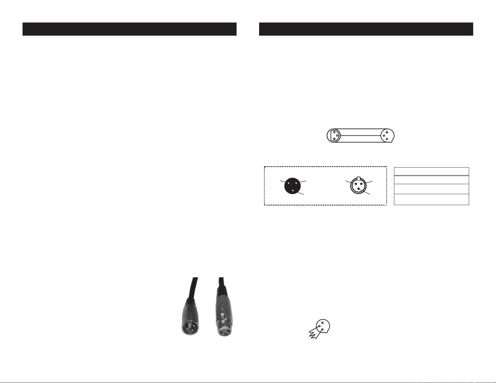
stores). Your cables should be made with a male
and female XLR connector on either end of the cable. Also remember
Figure 1
that DMX cable must be daisy chained and cannot be split.
Notice: Be sure to follow gures two and three when making your
own cables. Do not use the ground post on the XLR connector. Do
not connect the cable’s shield conductor to the ground lug or allow
the shield conductor to come in contact with the XLR’s outer casing.
Grounding the shield could cause a short circuit and erratic behavior.
COMMON
1
DMX512 IN
3
3-PIN XLR
2
Figure 2
XLR Pin Conguration
Pin 1 = Ground
Pin 2 = Data Compliment (negative)
Pin 3 = Data True (positive)
When longer runs of cable are
Figure 4
XLR Male Socket
1 Ground
DMX512 OUT
3-PIN XLR
2 Cold
3 Hot
1
2
3
2 Cold
DMX +
DMX -
XLR Female Socket
1 Ground
3 Hot
Figure 3
Special Note: Line Termination.
used, you may need to use a terminator on the last unit to avoid erratic
behavior. A terminator is a 90-120 ohm 1/4 watt resistor which is connected between pins 2 and 3 of a male XLR connector (DATA + and
DATA -). This unit is inserted in the female XLR connector of the last
unit in your daisy chain to terminate the line. Using a cable terminator
(ADJ part number Z-DMX/T) will decrease the possibilities of erratic
behavior.
Termination reduces signal errors and
1
avoids signal transmission problems
3
and interference. It is always advisable
2
to connect a DMX terminal, (Resistance
120 Ohm 1/4 W) between PIN 2 (DMX-)
©Elation Professionals® - www.elationlighting.com - TVL3000-II WW/CW/DW User Manual Page 6©Elation Professionals® - www.elationlighting.com - TVL3000-II WW/CW/DW User Manual Page 5
TVL3000-II WW/CW/DW Set Up
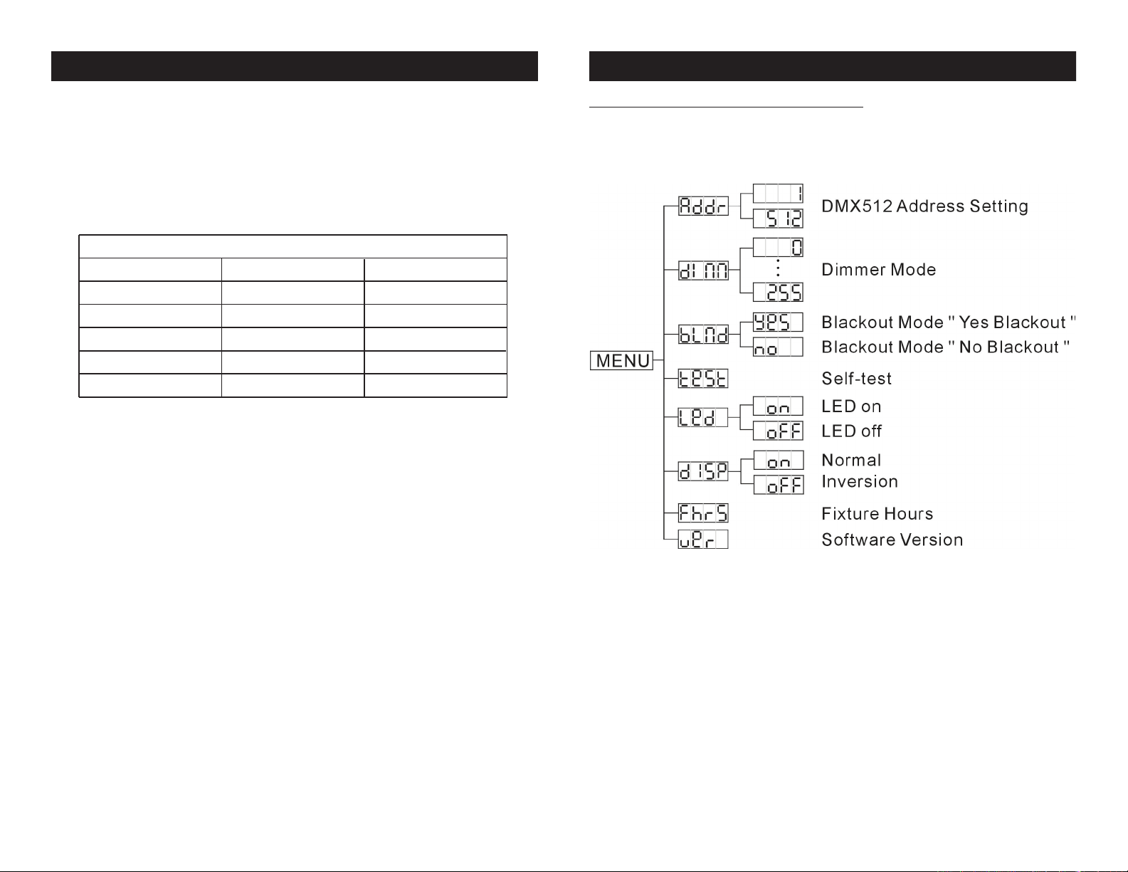
TVL3000-II WW/CW/DW System Menu
5-Pin XLR DMX Connectors.
Some manufactures use 5-pin XLR
connectors for DATA transmission in place of 3-pin. 5-pin XLR xtures
may be implemented in a 3-pin XLR DMX line. When inserting standard 5-pin XLR connectors in to a 3-pin line a cable adaptor must be
used, these adaptors are readily available at most electric stores. The
chart below details a proper cable conversion.
3-Pin XLR to 5-Pin XLR Conversion
Conductor 5-Pin XLR Male (In)3-Pin XLR Female (Out)
Ground/Shield
Data Compliment (- signal)
Data True (+ signal)
Not Used
Not Used
Pin 1
Pin 2
Pin 3
Pin 1
Pin 2
Pin 3
Pin 4 - Do Not Use
Pin 5 - Do Not Use
TVL3000-II WW/CW System Menu
©Elation Professionals® - www.elationlighting.com - TVL3000-II WW/CW/DW User Manual Page 7 ©Elation Professionals® - www.elationlighting.com - TVL3000-II WW/CW/DW User Manual Page 8
 Loading...