

Page 1

RDMS6
6 Way RDM Splitter
User's Instruction
Page 2
Product Descriptions
This is a 6 way RMD splitter, features one RDM IN/THRU and 6 RDM OUTPUTs. This unit takes the incoming
RDM/DMX signal and splits the signal into six separate OUTPUT channels. Each OUTPUT and the IN/THRU
are completely electronically isolated from each other, all six OUTPUT ports have independent output driver to
boost the RDM/DMX signal.
Technical Specifications
POWER INPUT
.................................................................................................................................AC 100~240V
POWER CONSUMPTION ..................................................................................................................................5W
RDM IN/THRU,RDM OUTPUT
DIMENSIONS
WEIGHT
............................................................................................................................264x133.3x120mm
.......................................................................................................................................................1.45Kg
.......................................................................................................Via 5-pin terminal
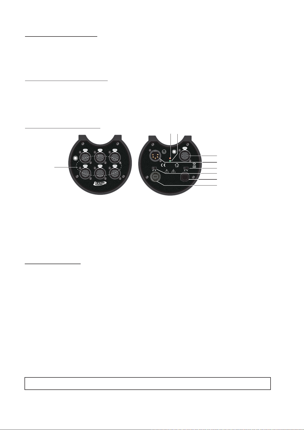
Function Descriptions
8
9
RDMOUT1-6
12
1=Ground
2=Data3=Data+
1
4,5=NC
4
RDMS6
6Way RDMBoost
3
5
6
RoHS
LinkOut/
1.RDM OUT 1~6: via 3-pin XLR connector.
2.RDM Thru: via 3-pin XLR connector.
3.RDM IN: via 3-pin XLR connector.
4.RDM/DMX switch: selects signal inputs.
5.Link Out/Terminate switch: selects Link Out or Terminate.
6.Power In: Inputs a power of 100~240V AC,50/60Hz.
7.Fuse:
8.Power Indicator: It will light when contacts to the suitable power source.
9.Signal Indicator: it will blink when RB-6 TS detects any signal inputs.
RDM IN
FUSE
Terminate
ACIN:
1=Ground
2=Data-
3=Data+
4,5=NC
Power
Signal
CAUTION!
Riskof Electric Shock
DONOT OPEN
Nepas ouvrir. Risque
dechoc electrique
Warning:Thisapparatus
mustbe earthed
100-240V~50/60Hz,1A Max.
Fuse:
F1A250V 5x20mm
Madein P.R.C.
RDM THRU
RDM DMX
ACIN
2
3
4
5
6
7
Operation Guide
Set the RDM/DMX switch as "DMX", the RDMS6 applies to DMX signal input only and the Input/Output
Signal is mono-directional communication.
Set the RDM/DMX switch as "RDM", the RDMS6 applies to DMX or RDM signal input and the Input/Output
Signal is bidirectional communication.
While need one RDMS6 in system only for operation(thus the RDM Thru needn't connect to the next
RDMS6), the user may move the end-switch to terminal end for connecting to end-resistor. Regarding the
other status, the end-switch should be disconnected to put through the RDM In and RDM Thru.
The signal indicator will blink when RDMS6 detects any signal inputs.
Data Cable (DMX Cable) Requirements:
The RDMS6 is controlled via DMX-512 protocol and your DMX controller requires a standard 3-pin terminal
connector for data input and data output. Connect the RDMS6 and your fixtures together using standard 3pin DMX cables.
DMX Signal Cable. 120 ohm impedance DMX signal cable be used for signal connection.MUST
24-004-3067-00
Rev1.0
 Loading...