

Elation ProTron LED User Manual

ProTron LED
USER MANUAL
Version 2.0 24-004-3533-00

2
TABLE OF CONTENTS
TABLE OF CONTENTS
PREFACE
About this Manual
Included Items
Accessories
ProTron LED Luminaire Power Input Cables (North American Models Only)
ProTron LED Luminaire Accessories
ProTron LED LUMINAIRE OVERVIEW
ProTron LED Luminaire Components
Major Luminaire Components
LCD Display / Menu System
INSTALLATION AND SET UP
Power Requirements
AC Power Operation
Connecting Power
Connecting LED Luminaires to AC PowerProTron
Connecting to the DMX512 Network
Mounting Luminaire
OPERATION AND PROGRAMMING
LCD Display and Menu System
LCD Display and Menu System Operation
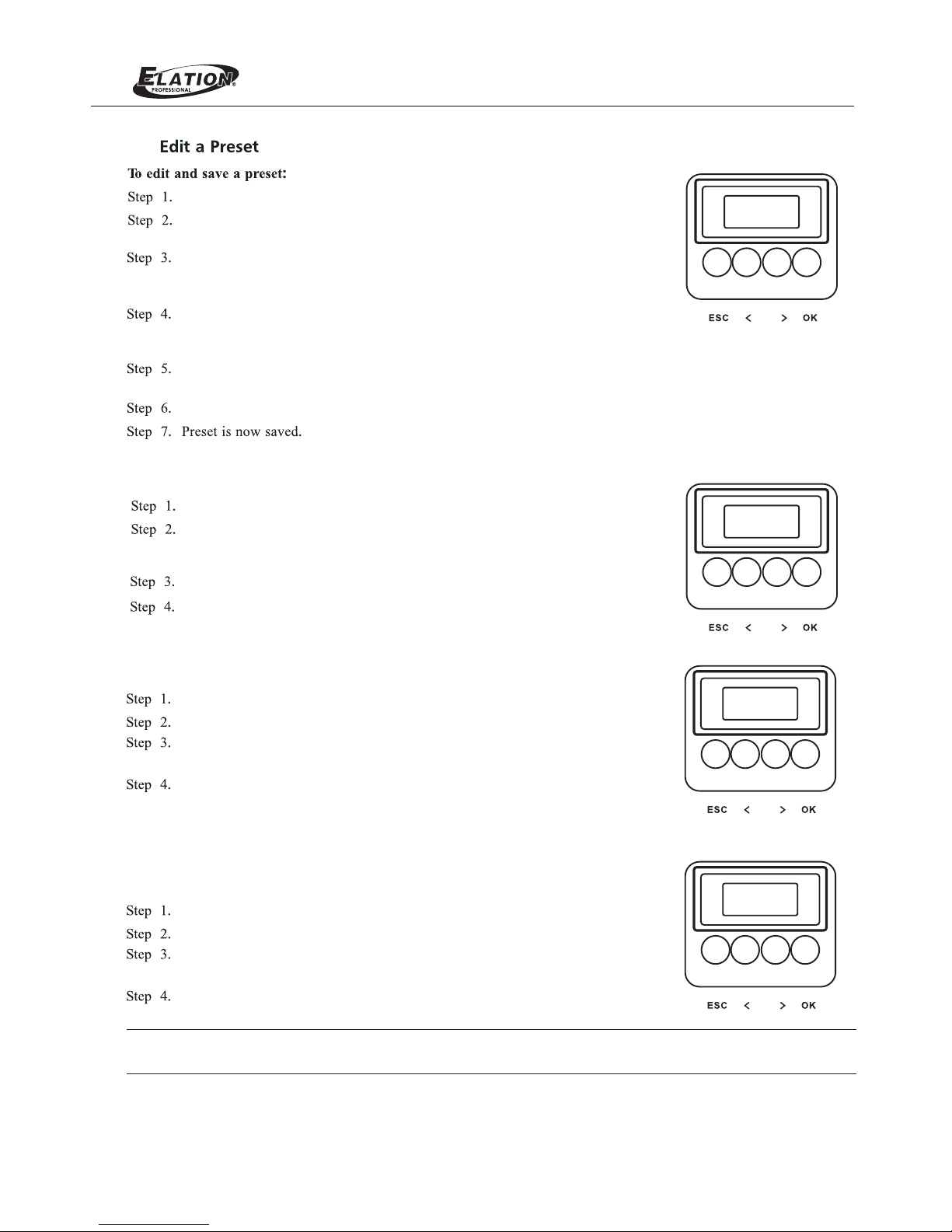
Edit a Preset
Settings
Status
Dimming Curve Selection
ProTron LED Luminaires Menu Tree
Master / Slave Operational Mode
DMX CONTROL
Single Channel Mode
Three Channel Mode
Four Channel Mode
16-Bit Mode
Custom Mode
Zone Mapping Mode
ProTron LED Luminaire RDM Parameter IDs
CLEANING AND CARE
Special Cleaning and Care Instructions
Front Lens Cleaning
Service and Maintenance
TECHNICAL SPECIFICATIONS
APPENDIX
ProTron LED Luminaire Operational Specifications
APPENDIX I
APPENDIX II
APPENDIX II
ProTron LED Luminaire Dimensions
23
........................................................................................................................................
..............................................................................................................................................
.................................................................................................................................................
......................................................................................................................................
.........................................................................................................................................
......................................................................................................................................
...............................................................................................................................
................................................................................................................
..................................................................................................................
...................................................................................................................
.....................................................................................................................
.......................................................................................................
................................................................................................................................
....................................................................................................................................
....................................................................................................................................
......................................................................................................................................
...............................................................................................................................................
...............................................................................................................................................
...................................................................................................................................
.......................................................................................................................................
.......................................................................................................................................
.........................................................................................................................................
................................................................................................................
...............................................................................................................................
...................................................................................................................
...................................................................................................
.............................................................................................................
.....................................................................................................................................
...............................................................................................................................
..................................................
........................................................................................................
..............................................................................................................
....................................................................................
...........................................................................................
..............................................................................................................................................
..............................................................................................................................................
..............................................................................................................................................
...............................................................................................................
3
3
3
3
3
4
4
5
6
6
6
6
7
8
9
9
9
9
9
9
11
12
13
14
14
15
16
17
18
18
22
22
22
23
24
30
35
Chase
ProTron LED

3
PREFACE
1. About this Manual
The document provides installation and operation instructions for the following products:
LED LuminaireProTron
Please read all instructions before installing or using this product. Retain this manual for future reference. Additional
product information and descriptions may be found on the product specification sheet.
Note: The LED Luminaire is univProTron ersal voltage 100 to 240 VAC (auto-ranging).
2. Included Items
Each LED LuminaProTron ire includes the following items:
LED Luminaire ProTron
Installation and User’s Manual (this document)
3. Accessories
P roTron LED Luminaire Power Input Cables (North American Models Only)
ProTron LED Luminaire Accessories
Part Number Description
PC1BE
ProTron LED Luminaire AC Power Input Cable (39 inches / 1 meter), Powercon with Bare
End* (*Note, user supplies and installs own AC input connector)
PC1GP
ProTron Stagepin Connector LED Luminaire AC Power Input Cable (39 inches / 1 meter), Powercon with
PC1GTL
ProTron Twistlock Connector LED Luminaire AC Power Input Cable (39 inches / 1 meter), Powercon with
PC1GR
ProTron Edison Connector LED Luminaire AC Power Input Cable (39 inches / 1 meter), Powercon with
PC3BE
ProTron End LED Luminaire AC Power Input Cable (9.8 Feet / 3 meter), Powercon with Bare
PC8BE
ProTron End LED Luminaire AC Power Input Cable (26 Feet / 8 meter), Powercon with Bare
PC8GR
ProTron Connector LED Luminaire AC Power Input Cable (26 Feet / 8 meter), Powercon with Edison
Part Number Description
MC Mega Claw, Black, Anodized
SC Molded Yoke C-Clamp
HC Light Weight Half Coupler
82003 Safety Cable
ProTron LED
4
ProTron LED LUMINAIRE OVERVIEW
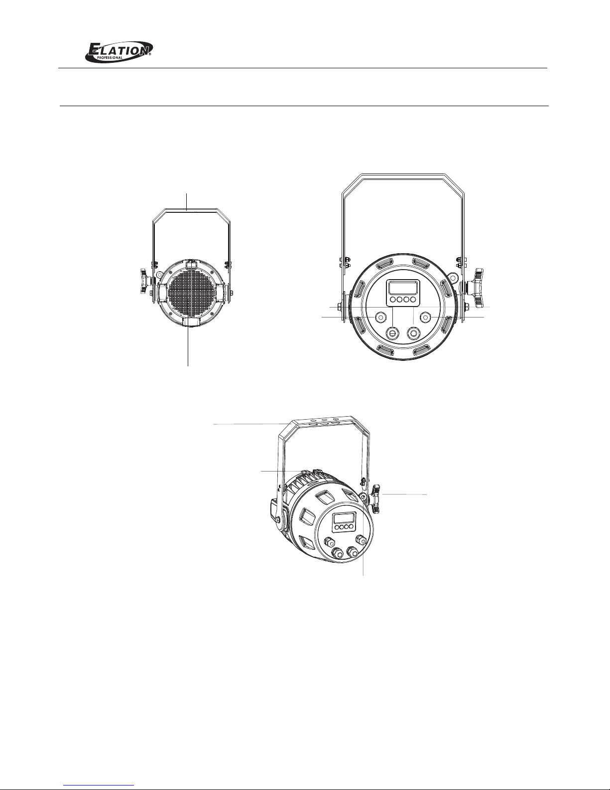
1. ProTron LED Luminaire Components
Major Luminaire Components
Figure 1: ProTron LED Luminaire Components
ProTron LED
DMX512 /
AC Input
RDM Input
DMX512 /
AC Output
RDM Output
Yoke Assem bly
High Int ensity LED Array
Yoke(Tilt) Position
Lockin g handle
Lumina ire Head
Assemb ly
Tru ss Hook / Clamp*
Attach ment Point
Safety ca ble anc hor point
5
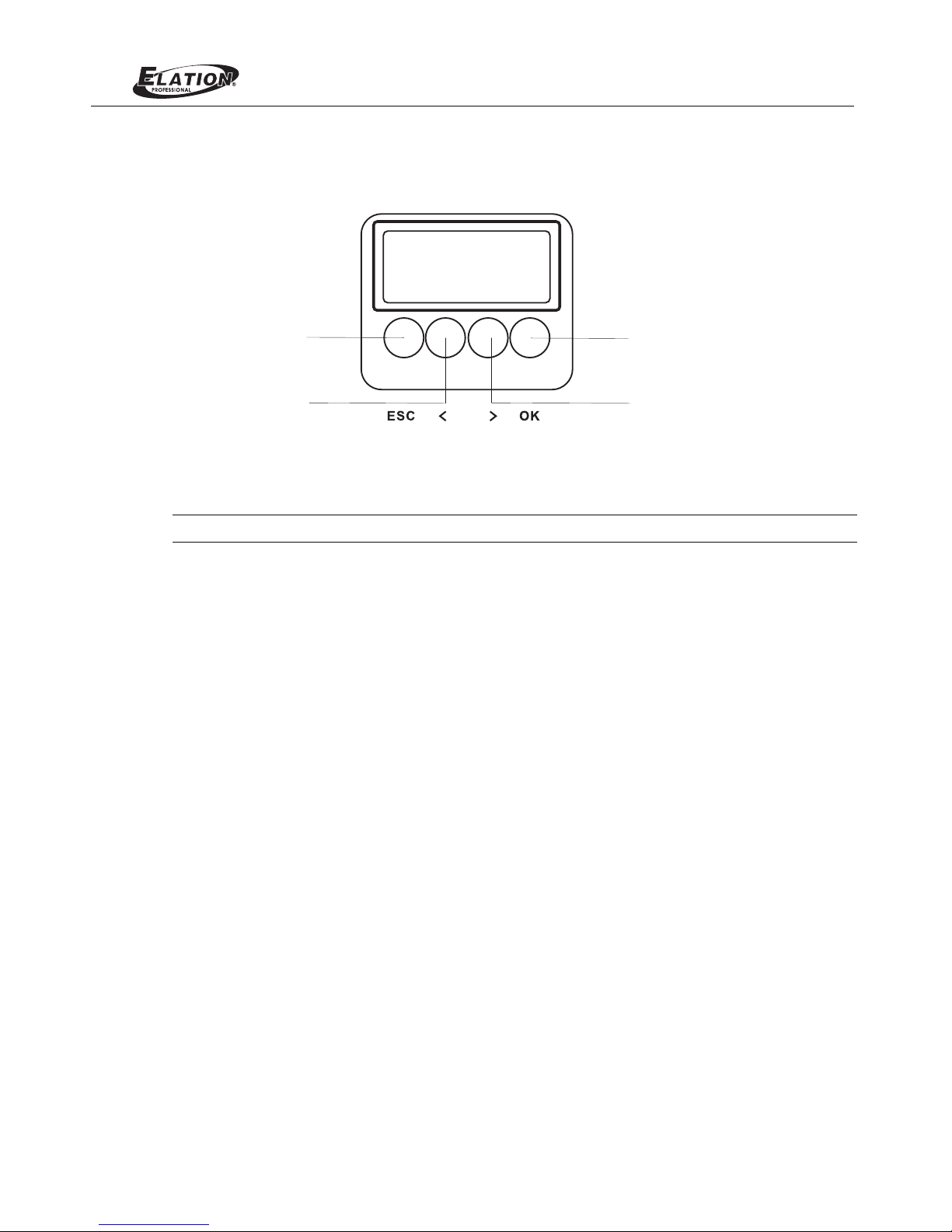
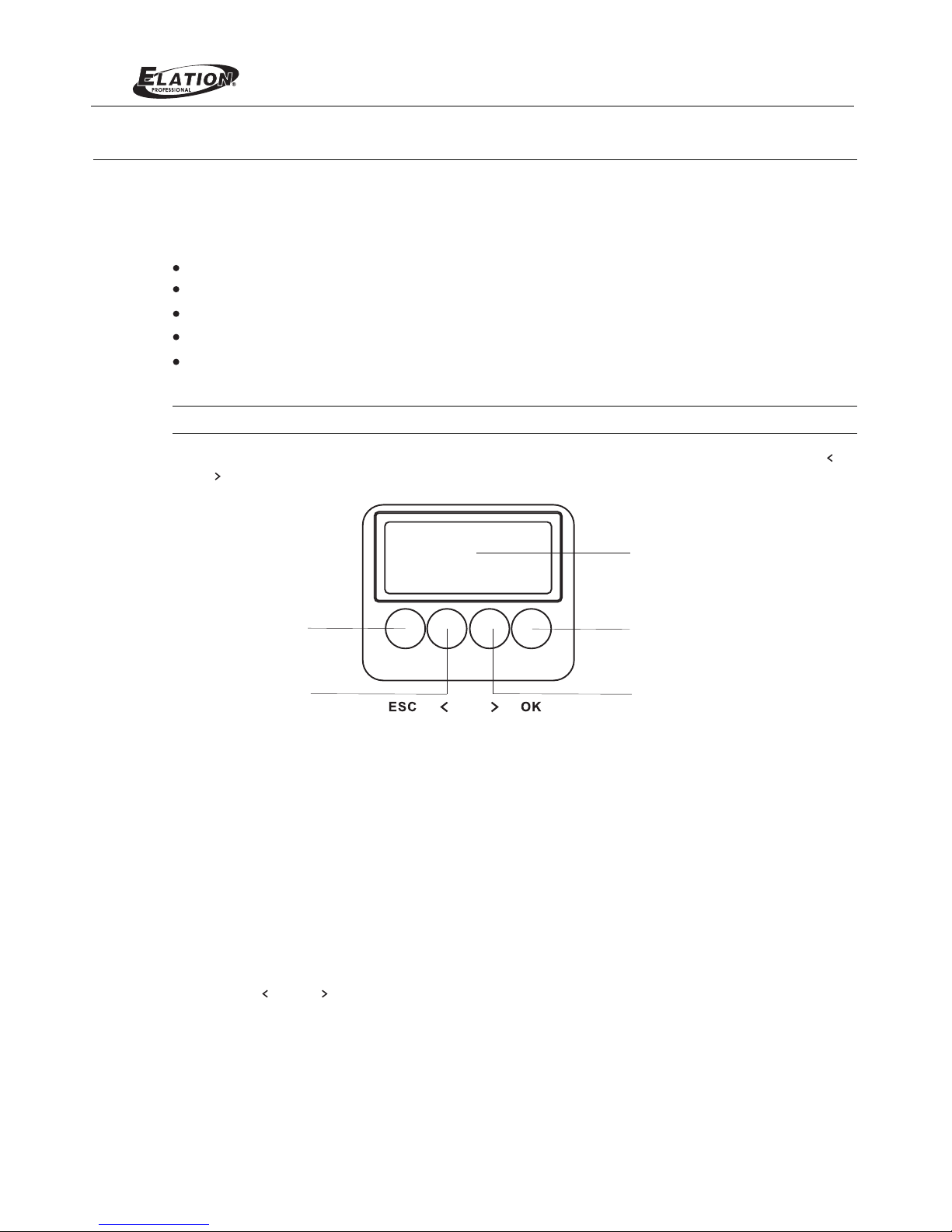
LCD Display / Menu System
Figure 2: LCD Display & Menu System
Note: For Menu operation and programming details, refer to "LCD Display and Menu System" on page 9.
LEFT Arro w Bu tton
RIGH T Arrow B utton
CHEC K MARK(OK) Bu tton
EXIT Butto n
ProTron LED
6
INSTALLATION AND SET UP
1. Power Requirements
The ProTron LED Luminaire operates on AC input voltages from 100 to 240 VAC.
WARNING! This unit does not contain an ON/OFF switch. Always disconnect power input cable to completely
remove power from unit when not in use.
AC Power Operation
When connected to an AC source, the unit operates on 100 to 240 volts AC (+/- 10%, auto-ranging). The luminaire
contains an auto-ranging power supply. Each luminaire can draw up to 150 Watts.
WARNING!
Maximum amount of units that may be daisy-chained is (A) 10 units 100 ~ 120VAC (15 Amps) or (B)
20 (15 Amps).units 230 ~ 240VAC
Note:
Note:
For wiring of AC input connector, refer to "Connecting ProTron LED Luminaires to AC Power" on page 6
The ProTron LED Luminaires has to be cooled down for 20min after it continuously works for 30 minutes.
Keep working continuously will do great harm to the luminaire.
.
2. Connecting Power
Units can be powered in one of two ways:
Direct connection to an AC power sour ce using an AC input cable. For wiring of AC input connector, refer to "Con-
necting LED Luminaires to AC Power" on page 6ProTron .
Connection from the AC output of another ProTron LED Luminaire. When using this method, it is very important
to connect any other type of equipment device. not
WARNING! Only connect other ProTron LED Luminaires to the AC Output (Thru) connector of an ProTron LED
Luminaire.
Connecting ProTron LED Luminaires to AC Power
Table 2 on page 7 describes how to connect power to your ProTron L ED Luminaire. Field wiring of the ProTron
LED Luminaire is straight forward. A total of 3 wires/conductors is supplied from the unit. The following wiring
scheme is used:
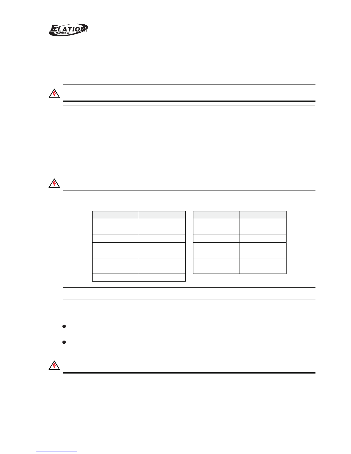
Table 1: ProTron LED Luminaire Voltage (VAC) vs. Current*
Voltage (AC) Total Current (A) Voltage (AC) Total Current (A)
100 1.50 180 0.83
110 1.36 190 0.79
120 1.25 200 0.75
130 1.15 210 0.70
140 1.07 220 0.68
150 1.00 230 0.65
160 0.94 240 0.63
170 0.88
ProTron LED
Or there w ill be an power r eduction fu nction added, when the power output is at 100 % for 30 min ,
the powe r output will b e deduced to 50 % gradually; when the power output is lower t han 100%, the p ower
output w ill also be ded uced to 50% gra dually, but will tak e more than 30 mi n to finish the d eduction.
contin uously

7
Table 2: ProTron LED Luminaire (IP65 Rated Models) AC Input Connections
Figure 3: ProTron LED Luminaire AC Input & Output Connections
CAUTION: In the event the AC input cable of this luminaire is damaged, it must be replaced, by the user, with an
approved cable through an Authorized Dealer or Service Center.
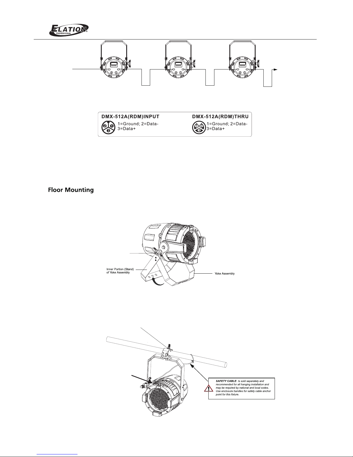
3. Connecting to the DMX512 Network
Basic DMX512 installation consists of connecting multiple ProTron LED Luminaires together (up to 32 luminaires)
in "daisy-chain" fashion. A cable runs from the control console (or DMX512 control source) to the DMX connector
on the first LED Luminaire. ProTron the first unit to a DMXAnother cable runs from the other DMX connector on
connector on the next ProTron LED Luminaire (or DMX512 device to be controlled).
Figure 4: ProTron LED Luminaire DMX512 Input / Output Connections
Back of Unit
ProTron LED
Note: For more information on DMX512 networking and systems, refer to "Additional Resources for DMX512" on
page 1. For ProTron LED Luminaire DMX Mapping, refer to "DMX CONTROL" on page 13
.
DMX512 /
AC Input
RDM Input
DMX512 /
AC Output
RDM Output
8
Figure 5: ProTron LED Luminaire - DMX512 Connections
4. Mounting Luminaire
ProTron LED Luminaires
The LED Luminaires are designed to sit directly on its yoke assembly in a floor installation application. ProTron When used
in this type of application, loosen the locking handle securing the inner shown inportion of the yoke assembly and out (as
Figure 6). Be sure to leave enough soace around the luminaire to allow proper, uninterrupted airflow for cooling.
Figure 6: Floo r Mo unting
ProTron LED
DMX512
DMX512 (out from first
to second luminaire)
DMX512 (out to the next
luminaire or DMX512
controlled device)
(from console or
control device)
Yoke( Tilt) P ositi on
Loc king ha ndle
Truss / Hanging Applications
The ProTron LED is provided with the ability to hang via truss hooks, clamps, etc. (sold separately).
Safety Cable Anchor Point
Truss Hook or Clamp
(sold separately)
9
OPERATION AND PROGRAMMING
1. LCD Display and Menu System
The LED Luminaire’ProTron followings LCD Display and Menu System provides local control for accessing the
fixture’s settings:
Presets (Standard and User Defined)
Fixture Settings
Effects(Chases - preloaded and user defined)
Current Fixture Operational Status
Setting the DMX512 Address
Note: If there are multiple luminaires in a system, changes would need to be made at each LCD Menu as desired.
Upon power up, the LCD will display the main screen showing menu of ProTron LED. User can use “ ”
and “ ” to select then enter the desired function menu.
Figure 7: LCD Display and Menu System
2. LCD Display and Menu System Operation
The LCD Display Menu system consists of several categories. Upon power up, the LCD will display the main
menu automatically. There are totally 4 menus available including Preset, Chase, Settings and Status. When the
navigate and desired menu item is reached, press OK button to display the menu options and to configure the
LEFT Arro w Bu tton
RIGH T Arrow B utton
CHEC K MARK(OK) Bu tton
LCD Di splay
EXIT Butto n
To navigate and access menu settings/selections:
Step 1. Make sure unit is powered and turned on.
Step 2. Press the desired button to access menu categories.
Step 3. Use “ ” and “ ” arrow buttons to navigate through
Step 4. Make changes as desired.
Press OK button to accept changes.
the various options and settings.
menu options as required.
ProTron LED
Press CH ECK MARK(OK )button to ac cess Preset Select.
Press CH ECK MARK(OK )button to ac cess Chase.
Press CH ECK MARK(OK )button to ac cess Settings.
Press CH ECK MARK(OK )button to ac cess Status.
Use LEFT and RIG HT arrow buttons to s croll throu gh all preset s
and sele ct Preset x(0 t hru 31).
Use LEFT and RIG HT arrow buttons to s croll throu gh all menus,
includ ing Chase Sel ect, Master Inten sity, Strobe Rate, Strob e
Durati on and Edit Use rcha se.
Use LEFT and RIG HT arrow buttons to s croll throu gh all menus.
Use LEFT and RIG HT arrow buttons to s croll throu gh all menus.
Once at de sired prese t, use LEFT and RIGHT arrow b uttons to
adjust p arameter va lue as desire d. Once all values are adjusted as
desire d, press CHEC K MARK(OK)b utton.
Once at de sired menu, u se LEFT and RIGHT arrow but tons to
adjust p arameter va lue as desire d. Once all values are adjusted as
desire d, press CHEC K MARK(OK)b utton.
Once at de sired menu, u se LEFT and RIGHT arrow but tons to
adjust p arameter va lue as desire d. Once all values are adjusted as
desire d, press CHEC K MARK(OK)b utton.
Once at de sired menu, u se LEFT and RIGHT arrow but tons to
check th e related fix ture inform ation.
Press CH ECK MARK(OK )button to se lect the desired menu among
Intens ity, Strobe Rate, Du ration and Ef fects, Zone1, Z one2,
Zone3 an d Zone4.
Press CH ECK MARK(OK )button to se lect the desired menu.
Press CH ECK MARK(OK )button to se lect the desired menu
among Ge neral, Fact ory Default , DMX and Displ ay.
Press CH ECK MARK(OK )button to se lect the desired menu
among LE D Current Level, Temper ature, and Other Inform ation.
If savin g preset, pre ss CHECK MARK (OK) button. Confirm choice.
Save pre set menu opti on will appea r. Us e LEFT and RIGHT arrow
button s to select pre set number.
Settings
Status
Note: Fo r more inform ation about P reset, Settings and Status, please refe r to “ LED Lumi naire Menu Tre e”
on page 11.
ProTron
To check t he fixture operat ional statu s:
..P reset E dit
1. In tensi ty
..C hase
1. Ch ase Sel ect
Setti ngs
1. Gene ral
Sta tu s
1. LED Le vel
Chase
10
ProTron LED
3.
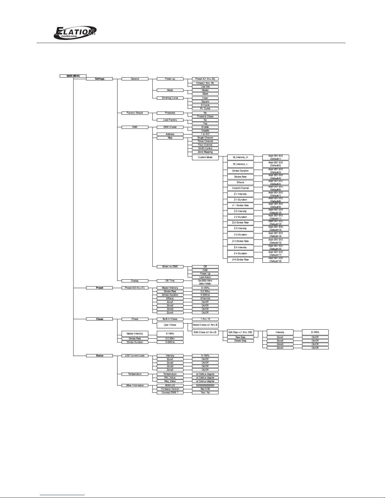
4. LED Luminaire Menu TreeProTron
Figure 8: ProTron LED Luminaire Menu Tree
11
ProTron LED
 Loading...