

Page 1

ELATION
|
PROTRON ECLYPSE
|
user manual
!
user manual
Page 2

©2018 ELATION PROFESSIONAL all rights reserved. Information, specifications,
Date
Document
Version
Software
Version ≥
DMX
Channel Modes
Notes
11/16/18
1
1.1
57
Initial preliminary release.
01/23/19
1.2
N/C
NO CHANGE
Updated Hour Average LED Life Spec
01/24/19
1.4
N/C
24
Updated specs.
diagrams, images, and instructions herein are subject to change without notice. ELATION
PROFESSIONAL logo and identifying product names and numbers herein are trademarks
of ELATION PROFESSIONAL. Copyright protection claimed includes all forms and matters
of copyrightable materials and information now allowed by statutory or judicial law or
hereinafter granted. Product names used in this document may be trademarks or
registered trademarks of their respective companies and are hereby acknowledged. All
non-ELATION brands and product names are trademarks or registered trademarks of their
respective companies.
ELATION PROFESSIONAL and all affiliated companies hereby disclaim any and all
liabilities for property, equipment, building, and electrical damages, injuries to any persons,
and direct or indirect economic loss associated with the use or reliance of any information
contained within this document, and/or as a result of the improper, unsafe, insufficient and
negligent assembly, installation, rigging, and operation of this product.
Elation Professional USA | 6122 S. Eastern Ave. | Los Angeles, CA. 90040
323-582-3322 | 323-832-9142 fax | www.elationlighting.com | info@elationlighting.com
Elation Professional B.V. | Junostraat 2 | 6468 EW Kerkrade, The Netherlands
+31 45 546 85 66 | +31 45 546 85 96 fax | www.elationlighting.eu | info@elationlighting.eu
Elation Professional Mexico | AV Santa Ana 30 | Parque Industrial Lerma, Lerma, Mexico 52000
+52 (728) 282-7070
DOCUMENT VERSION
Due to additional product features and/or enhancements, an updated
version of this document may be available online.
Please check www.elationlighting.com for the latest revision/update of this
manual, before beginning installation and/or programming.
2
Page 3

CONTENTS
General Information
4
Limited Warranty (USA Only)
5
Safety Guidelines
6
Maintenance Guidelines
8
Fixture Overview
9
Installation Guidelines
10
System Menu
18
Pixel Zone Control
20
DMX Channel Functions and Values
21
Specifications
24
Optional Accessories
26
3
Page 4

GENERAL INFORMATION
INTRODUCTION
Please read and understand the instructions in this manual carefully and thoroughly before
attempting to operate this device. These instructions contain important safety and use
information.
UNPACKING
Every device has been thoroughly tested and has been shipped in perfect operating
condition. Carefully check the shipping carton for damage that may have occurred during
shipping. If the carton is damaged, carefully inspect the device for damage, and be sure all
accessories necessary to install and operate the device have arrived intact. In the event
damage has been found or parts are missing, please contact our customer support team
for further instructions. Please do not return this device to your dealer without first
contacting customer support. Please do not discard the shipping carton in the trash.
Please recycle whenever possible.
BOX CONTENTS
(1) Omega Bracket
(1) Seetronic IP65 Power Cable
CUSTOMER SUPPORT
Contact ELATION Service for any product related service and support needs.
Also visit forums.elationlighting.com with questions, comments or suggestions.
ELATION SERVICE USA - Monday - Friday 8:00am to 4:30pm PST
323-582-3322 | Fax 323-832-9142 | support@elationlighting.com
ELATION SERVICE EUROPE - Monday - Friday 08:30 to 17:00 CET
+31 45 546 85 63 | Fax +31 45 546 85 96 | support@elationlighting.eu
REPLACEMENT PARTS please visit parts.elationlighting.com
IMPORTANT NOTICE!
THERE ARE NO USER SERVICEABLE PARTS INSIDE THIS UNIT.
DO NOT ATTEMPT ANY REPAIRS YOURSELF; DOING SO WILL VOID YOUR
MANUFACTURES WARRANTY. D A M A G E S R E S U L T I N G FROM MODIFICATIONS TO
THIS FIXTURE AND/OR THE DISREGARD OF SAFETY INSTRUCTIONS AND
GUIDELINES IN THIS MANUAL VOID THE MANUFACTURES WARRANTY AND ARE
NOT SUBJECT TO ANY WARRANTY CLAIMS AND/OR REPAIRS.
4
Page 5

LIMITED WARRANTY (USA ONLY)
A. Elation Professional hereby warrants, to the original purchaser, Elation Professional products to be free of
manufacturing defects in material and workmanship for a period of two years (730 days), and Elation
Professional product rechargeable batteries to be free of manufacturing defects in material and workmanship for
a period of six months (180 days), from the original date of purchase. This warranty excludes discharge lamps
and all product accessories. This warranty shall be valid only if the product is purchased within the United
States of America, including possessions and territories. It is the owner’s responsibility to establish the date and
place of purchase by acceptable evidence, at the time service is sought. B. For warranty service, send the
product only to the Elation Professional factory. All shipping charges must be pre-paid. If the requested repairs
or service (including parts replacement) are within the terms of this warranty, Elation Professional will pay return
shipping charges only to a designated point within the United States. If any product is sent, it must be shipped
in its original package and packaging material. No accessories should be shipped with the product. If any
accessories are shipped with the product, Elation Professional shall have no liability what so ever for loss and/or
or damage to any such accessories, nor for the safe return thereof. C. This warranty is void if the product serial
number and/or labels are altered or removed; if the product is modified in any manner which Elation Professional
concludes, after inspection, affects the reliability of the product; if the product has been repaired or serviced by
anyone other than the Elation Professional factory unless prior written authorization was issued to purchaser by
Elation Professional; if the product is damaged because not properly maintained as set forth in the product
instructions, guidelines and/or user manual. D. This is not a service contract, and this warranty does not include
any maintenance, cleaning or periodic check-up. During the periods as specified above, Elation Professional will
replace defective parts at its expense, and will absorb all expenses for warranty service and repair labor by
reason of defects in material or workmanship. The sole responsibility of Elation Professional under this warranty
shall be limited to the repair of the product, or replacement thereof, including parts, at the sole discretion of
Elation Professional. All products covered by this warranty were manufactured after January 1, 1990, and bare
identifying marks to that effect. E. Elation Professional reserves the right to make changes in design and/or
performance improvements upon its products without any obligation to include these changes in any products
theretofore manufactured. F. No warranty, whether expressed or implied, is given or made with respect to any
accessory supplied with the products described above. Except to the extent prohibited by applicable law, all
implied warranties made by Elation Professional in connection with this product, including warranties of
merchantability or fitness, are limited in duration to the warranty periods set forth above. And no warranties,
whether expressed or implied, including warranties of merchantability or fitness, shall apply to this product after
said periods have expired. The consumer’s and/or dealer’s sole remedy shall be such repair or replacement as is
expressly provided above; and under no circumstances shall Elation Professional be liable for any loss and/or
damage, direct and/or consequential, arising out of the use of, and/or the inability to use, this product. G. This
warranty is the only written warranty applicable to Elation Professional products and supersedes all prior
warranties and written descriptions of warranty terms and conditions heretofore published.
WARRANTY RETURNS
All returned service items whether under warranty or not, must be freight pre-paid and accompany a return
authorization (R.A.) number. The R.A. number must be clearly written on the outside of the return package. A
brief description of the problem as well as the R.A. number must also be written down on a piece of paper and
included in the shipping container. If the unit is under warranty, you must provide a copy of your proof of
purchase invoice. Items returned without a R.A. number clearly marked on the outside of the package will be
refused and returned at customer’s expense. You may obtain a R.A. number by contacting customer support.
5
Page 6
SAFETY GUIDELINES
PROTECTION CLASS 1 - FIXTURE MUST BE PROPERLY GROUNDED
THERE ARE NO USER SERVICEABLE PARTS INSIDE THIS UNIT.
DO NOT ATTEMPT ANY REPAIRS YOURSELF; DOING SO WILL VOID
YOUR MANUFACTURES WARRANTY. DAMAGES RESULT I NG FROM
MODIFICATIONS TO THIS FIXTURE AND/OR THE DISREGARD OF
SAFETY INSTRUCTIONS AND GUIDELINES IN THIS MANUAL VOID
THE MANUFACTURES WARRANTY AND ARE NOT SUBJECT TO ANY
WARRANTY CLAIMS AND/OR REPAIRS.
DO NOT PLUG FIXTURE INTO A DIMMER PACK!
NEVER OPEN THIS FIXTURE WHILE IN USE!
UNPLUG POWER BEFORE SERVICING FIXTURE!
NEVER TOUCH FIXTURE DURING OPERATION, AS IT MAY BE HOT!
KEEP FLAMMABLE MATERIALS AWAY FROM FIXTURE!
ENSURE ALL CONNECTIONS AND END CAPS ARE PROPERLY
SEALED WITH A DIELECTRIC GREASE (AVAILABLE AT MOST
ELECTRICAL SUPPLIERS) TO PREVENT WATER CORROSION
AND/OR ELECTRICAL SHORT CIRCUIT.
NEVER LOOK DIRECTLY INTO THE LIGHT SOURCE!
RETINA INJURY RISK - MAY INDUCE BLINDNESS!
SENSITIVE PERSONS MAY SUFFER AN EPILEPTIC SHOCK!
This fixture is a sophisticated piece of electronic equipment. To guarantee a smooth
operation, it is important to follow all instructions and guidelines in this manual. Elation
Professional is not responsible for injury and/or damages resulting from the misuse of this
fixture due to the disregard of the information printed in this manual. Only qualified and/or
certified personnel should perform installation of this fixture and only the original rigging
parts (omega brackets) included with this fixture should be used for installation. Any
modifications to the fixture and/or the included mounting hardware will void the original
manufactures warranty and increase the risk of damage and/or personal injury.
6
Page 7

SAFETY GUIDELINES
DO NOT TOUCH the fixture housing during operation. Turn OFF the power and allow
approximately 15 minutes for the fixture to cool down before serving.
DO NOT shake fixture, avoid brute force when installing and/or operating fixture.
DO NOT operate fixture if the power cord is frayed, crimped, damaged and/or if any of the
power cord connectors are damaged and do not insert into the fixture securely with ease.
NEVER force a power cord connector into the fixture. If the power cord or any of its
connectors are damaged, replace it immediately with a new one of similar power rating.
DO NOT block any air ventilation slots.
All fan and air inlets must remain clean and never blocked.
Allow approx. 6” (15cm) between fixture and other devices or a wall for proper cooling.
When installing fixture in a suspended environment, always use mounting hardware that is no
less than M10 x 25 mm, and always install fixture with an appropriately rated safety cable.
Always disconnect fixture from main power source before performing any type of service
and/or cleaning procedure. Only handle the power cord by the plug end, never pull out the
plug by tugging the wire portion of the cord.
During the initial operation of this fixture, a light smoke or smell may emit from the interior of
the fixture. This is a normal process and is caused by excess paint in the interior of the casing
burning off from the heat associated with the lamp and will decrease gradually over time.
Consistent operational breaks will ensure fixture will function properly for many years.
ONLY use the original packaging and materials to transport the fixture in for service.
7
Page 8

MAINTENANCE GUIDELINES
DISCONNECT POWER BEFORE PERFORMING ANY MAINTENANCE!
CLEANING
Frequent cleaning is recommended to insure proper function, optimized light output, and
an extended life. The frequency of cleaning depends on the environment in which the
fixture operates: damp, smoky or particularly dirty environments can cause greater
accumulation of dirt on the fixture’s optics. Clean the external lens surface at least every 20
days with a soft cloth to avoid dirt/debris accumulation.
NEVER use alcohol, solvents, or ammonia-based cleaners.
MAINTENANCE
Regular inspections are recommended to insure proper function and extended life.
There are no user serviceable parts inside this fixture, please refer all other service issues to
an authorized Elation service technician. Should you need any spare parts, please order
genuine parts from your local Elation dealer.
Please refer to the following points during routine inspections:
A detailed electric check by an approved electrical engineer every three months, to make
sure the circuit contacts are in good condition and prevent overheating.
Be sure all screws and fasteners are securely tightened at all times. Lose screws may fall out
during normal operation resulting in damage or injury as larger parts could fall.
Check for any deformations on the housing, color lenses, rigging hardware and rigging
points (ceiling, suspension, trussing). Deformations in the housing could allow for dust to
enter into the fixture. Damaged rigging points or unsecured rigging could cause the fixture
to fall and seriously injure a person(s).
Electric power supply cables must not show any damage, material fatigue or sediments.
NEVER remove the ground prong from the power cable.
8
Page 9
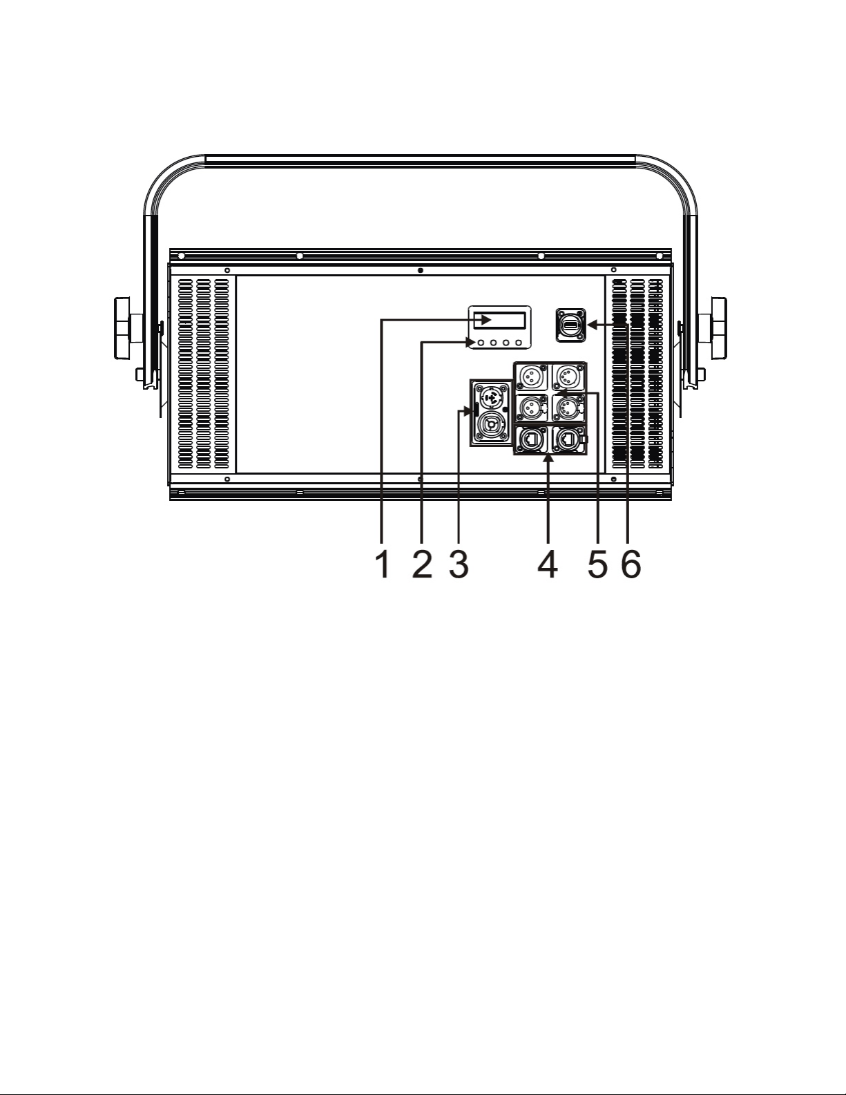
FIXTURE OVERVIEW
1. OLED Control Menu Display
2. MENU, DOWN, UP, ENTER Buttons
3. PowerKON IP65 Power IN/OUT
4. Ethernet RJ45 IN/OUT
5. 3pin/5pin DMX IN/OUT
9
Page 10

INSTALLATION GUIDELINES
IPX4 RATED
An IP rated lighting fixture is one, which is commonly installed in outdoor environments and
has been designed with an enclosure that effectively protects the ingress (entry) of external
foreign objects such as dust and water. The International Protection (IP) rating system is
commonly expressed as "IP" (Ingress Protection) followed by two numbers (i.e. IP20)
where the numbers define the degree of protection. The first digit (Foreign Bodies
Protection) indicates the extent of protection against particles entering the fixture and the
second digit (Water Protection) indicates the extent of protection against water entering the
fixture.
An IPX4 rated lighting fixture designed for temporary outdoor environments which has NOT
been tested to protect against the ingress of dust (X) but has been tested to protect from
splash of water in any direction (4).
PERMANENT OUTDOOR AND/OR MARINE/COSTAL INSTALLATIONS
Please note although this fixture is IP rated, this fixture is NOT suitable for permanent
outdoor and/or marine environment installations. Installing this fixture in permanent outdoor
and/or marine environment installation may cause corrosion and/or excessive wear to the
interior and/or exterior components of the fixture. Damages and/or performance issues
resulting from installation in a permanent outdoor and/or marine environment installation
will void the manufactures warranty and will NOT be subject to any warranty claims and/or
repairs.
FLAMMABLE MATERIAL WARNING
Keep fixture minimum 5.0 feet (1.5m) away from flammable materials and/or pyrotechnics.
ELECTRICAL CONNECTIONS
A qualified electrician should be used for all electrical connections and/or installations.
ENSURE ALL CONNECTIONS AND END CAPS ARE PROPERLY SEALED WITH
A NON-CONDUCTIVE DIELECTRIC GREASE (AVAILABLE AT MOST
ELECTRICAL SUPPLIERS) TO PREVENT WATER INGRESS/CONDENSATION
AND/OR CORROSION.
USE CAUTION WHEN POWER LINKING OTHER MODEL FIXTURES AS THE
POWER CONSUMPTION OF OTHER MODEL FIXTURES MAY EXCEED THE MAX
POWER OUTPUT ON THIS FIXTURE. CHECK SILK SCREEN FOR MAX AMPS.
10
Page 11

INSTALLATION GUIDELINES
SEAL ALL UNUSED
CONNECTIONCAPS
DO NOT INSTALL THE FIXTURE IF YOU ARE NOT QUALIFIED TO DO SO!
Fixture MUST be installed following all local, national, and country commercial electrical
and construction codes and regulations.
Before rigging/mounting a single fixture or multiple interconnected fixtures for custom
matrix designs to any metal truss/structure or placing the fixture(s) on any surface, a
professional equipment installer MUST be consulted to determine if the metal
truss/structure or surface is properly certified to safely hold the combined weight of the
fixture(s), clamps, cables, and accessories.
Fixture ambient operating temperature range is 14° to 113°F. (-10° to 45°C)
Do not use the fixture under or above this temperature.
Fixture(s) should be installed in areas outside walking paths, seating areas, or away from
areas were unauthorized personnel might reach the fixture by hand.
NEVER stand directly below the fixture(s) when rigging, removing or servicing.
Overhead fixture installation must always be secured with a secondary safety attachment,
such as an appropriately rated safety cable that meets all local, national, and country codes
and regulations. Allow approximately 15 minutes for the fixture to cool down before serving.
TO MAINTAIN IPX4 RATING INTEGRITY AND PREVENT WATER FROM ENTERING
FIXTURE, ALL UNUSED CONNECTION RUBBER CAPS MUST BE SEALED.
11
Page 12

INSTALLATION GUIDELINES
YOKE
HANDLE KNOB
SAFETY CABLE
ATTACHMENT
SAFETY CABLE
ATTACHMENT
YOKE
HANDLE KNOB
CLAMP MOUNTING
The adjustable yoke bracket attached to the fixture includes 3-position holes for versatile
fixture positioning. Depending on rigging position of the fixture, it may be best to use more
than one clamp attached to the yoke. The included Omega Bracket can be attached to the
fixture for easy clamp rigging. When mounting this fixture to truss or a metal structure, be
sure to secure an appropriately rated clamp (not included) using an M10 screw.
WHEN USING THE ADJUSTABLE YOKE TO MOUNT THE FIXTURE, MAKE SURE
BOTH YOKE HANDLE KNOBS ARE SECURE BEFORE RIGGING FIXTURE! USE
AN APPROPRIATELY RATED CLAMP (NOT INCLUDED) USING AN M10 SCREW!
SAFETY CABLE Fixture includes 2 integrated safety cable rigging points. (see below)
ALWAYS ATTACH AN APPROPRIATELY RATED SAFETY CABLE (NOT
INCLUDED) THAT MEETS ALL LOCAL, NATIONAL, AND COUNTRY CODES
AND REGULATIONS WHENEVER INSTALLING FIXTURE IN A SUSPENDED
ENVIRONMENT!
12
Page 13

INSTALLATION GUIDELINES
LINKING FIXTURES
The fixture includes integrated spring-loaded locking pins which are used to connect
multiple fixtures together horizontally and vertically to create seamless custom matrix
designs. See below for fixture linking steps.
EACH FIXTURE MUST BE SECURED WITH ITS OWN SAFETY CABLE!
USE AN APPROPRIATELY RATED SAFETY CABLE (NOT INCLUDED) THAT
MEETS ALL LOCAL, NATIONAL, AND COUNTRY CODES AND REGULATIONS.
OVERHEAD RIGGING
Overhead rigging requires extensive experience, including amongst others calculating
working load limits, installation material being used, and periodic safety inspection of all
installation material and the fixture. If you lack these qualifications, do not attempt the
installation yourself. Improper installation can result in bodily injury and property damage.
Spring-Loaded Locking-Pins
1. The spring-loaded locking-pin has a stepped rail-block with two flat surfaces that, when
horizontally aligned with the rail, allow it to pass through (Notice that the ring orientation and the
flat surfaces of the stepped rail-block are perpendicular to each other).
2. Compress spring and turn locking-pin 90° (either direction) to lock pin into the rail. As the
rail-block of the spring-loaded locking-pin is stepped, it will snap the lock into place in a
horizontal orientation.
13
Page 14

INSTALLATION GUIDELINES
Horizontal Fixture Linking
1. Remove spring-loaded locking-pin, compress the spring enough to clear the rail, rotate ring to vertical
orientation (stepped rail-block to a horizontal orientation), and pull it straight out.
2. To horizontally secure two adjacent fixtures, each fixture has an integrated locking-pin
abutment-block that is activated to bridge and secure the adjoining unit.
3. Press-click the locking-pin abutment block to release the spring-loaded locking mechanism; this
will pop the abutment-block out towards the adjacent fixture.
14
Page 15

INSTALLATION GUIDELINES
Horizontal Fixture Linking
4. With both fixtures horizontally adjoined, align the locking-pin rail holes with the holes in the locking-pin
abutment-block, and insert one locking-pin into the first set of aligned holes.
5. Compress the spring of the first locking-pin and rotate the ring 90° to lock it into the rail. Insert and
lock a second locking-pin through the second set of aligned holes and ensure that the stepped
rail-block of the locking-pin is horizontally aligned with rail slot to pass it through rail slot.
6. Compress the spring of the second locking-pin and rotate the ring 90° to lock it into the rail.
15
Page 16

INSTALLATION GUIDELINES
Vertical Fixture Linking
1. To vertically secure two fixtures, each fixture has integrated locking-pin rails at the top and bottom.
With both fixtures vertically aligned, the bottom rail straddles the top rail of the bottom unit. Note that
the bottom middle rail is stepped and fits into the slot just in back of the middle rail at the top of the
bottom unit.
2. With the locking-pin rail holes aligned, insert a locking-pin at each end (compress the spring of the locking-pin and
rotate the ring 90° to lock it into the rail).
POWER LINKING
USE CAUTION WHEN POWER LINKING OTHER MODEL FIXTURES AS THE
POWER CONSUMPTION OF OTHER MODEL FIXTURES MAY EXCEED THE MAX
POWER OUTPUT ON THIS FIXTURE. CHECK SILK SCREEN FOR MAX AMPS.
KLING-NET / ART-NET CONNECTION
When connecting fixture to a network switch to control multiple devices, a Gigabit
Ethernet Switch that supports IGMP (Internet Group Management Protocol) is required.
Using a Gigabit Ethernet Switch that does not support IGMP can cause erratic behavior
of all connected devices to the switch. Click link below for more information about IGMP.
https://en.wikipedia.org/wiki/Internet_Group_Management_Protocol
16
Page 17

INSTALLATION GUIDELINES
5 MAX
5 MAX
MAXIMUM 5 FIXTURES CAN BE SAFELY LINKED VERTICALLY OR HORIZONTALLY!
NOTE: Illustration below shows optional bracket and clamp. (not included)
EACH FIXTURE MUST BE SECURED WITH ITS OWN SAFETY CABLE!
USE AN APPROPRIATELY RATED SAFETY CABLE (NOT INCLUDED) THAT
MEETS ALL LOCAL, NATIONAL, AND COUNTRY CODES AND REGULATIONS.
17
Page 18

SYSTEM MENU
The fixture includes an easy to navigate system menu where fixture settings can be
adjusted via the LCD control panel located on the back of the fixture. (see image below)
During normal operation, pressing the MODE button once will access the main menu.
Navigate through the various sub-menus by pressing the UP and DOWN buttons, press the
ENTER button to select a specific sub-menu, press the UP and DOWN buttons to adjust
the selected sub-menu settings, and press the ENTER button again to confirm the
sub-menu setting selection. Exit the main system menu at any time without making any
adjustments by pressing the MODE button.
To access the system menu press and hold the MODE button for 3 seconds. The LCD Menu
Control Display will shut OFF automatically about 1 minute from the last button press.
18
Page 19

S Y S T E M M E N U
Supports Software Versions: ≥ A1.1 B1.1
Features are subject to change without any prior written notice.
MENU
SUB MENU
OPTIONS / VALUES (Default Settings in BOLD)
DESCRIPTION
DMX Setting
DMX Address
001 ~ xxx
DMX Address Setting
Ethernet Setup
Ethernet IP
IP Address (xxx.xxx.xxx.xxx)
Enter Fixture IP Address
Subnet Mask
(xxx.xxx.xxx.xxx)
Enter Fixture Subnet Mask Address
Ethernet Port
Net (0-127)
Set Network
Subnet (0-15)
Set Subnet
Universe (0-15)
Set Universe
ArtNet To DMX
1. Disable
2. Enable
Enable ArtNet Protocol
Klingnet
1. Disable
2. Enable
Enable Klingnet Protocol
Channel Mode
RGB, RGB16bit, RGBW, RGBW16bit, Strobe,
1, 2V, 2H, 3, 4, 4A, 6, 6A, 6H, 12, 12A,
F1, F2V, F2H, F3, F4, F6V, F6H, F12
Set DMX Channel Mode
DMX last State
Black out
Hold
Function If NO DMX Detected
White Balance
Red
Green
Blue
125 - 255
125 - 255
125 - 255
Calibrate White Balance
Manual Control
Red
Green
Blue
White
Intnsity
Durate
Rate
000 - 255
000 - 255
000 - 255
000 - 255
000 - 255
000 - 255
000 - 255
Calibrate White Balance
Auto Test
Run Auto Test Mode
Fan Mode
1. Silent Mode
2. Auto Mode
3. High Mode
Set Fan Mode
Fixture Hours
000
Displays Total Fixture Use Hours
Tem p er at ur e
XXX F° / XXX C°
Display Fixture Internal Temperature
USB Upgrade
Enable Service Port for Software
Updates
Software
Version
A1.1 B1.1
Displays Fixture Software Version
Factory Reset
1. No
2. Yes
Reset Fixture Settings to Factory
Default
19
Page 20

PIXEL ZONE CONTROL
Pixel zones can be changed by selecting different Channel Modes in the system menu.
See diagrams below for which pixel zone corresponds to each Channel Mode.
20
Page 21

DMX CHANNEL FUNCTIONS AND VALUES
ELATION PROTRON ECLYPSE™ | DMX Channel Values / Functions (57 DMX Channels)
Supports Software Versions: ≥ 1.1
Features subject to change without any prior written notice.
*Pixel control of effects depends on DMX channel mode selected in system menu and/or orientation of fixture.
MODE / CHANNEL
VAL UE
FUNCTION
RGB
RGB
16 bit
RGBW
RGBW
16 bit
Strobe
1 2 3 4 6
12
1 1 1
INTENSITY
0-255
0-100%
2 2
INTENSITY FINE
0-255
16-bit FINE Adjustment
2 3 3
STROBE R ATE
0-6
OPEN
7-255
SLOW TO FAST
3 4 4
STROBE DURATION
0-255
MIN TO MAX
4 5 5
STROBE M ODE
0-4
STROBE
5
WASH ALERTNATE
6-42
RAMP UP
43-85
RAMP DOWN
86-128
RAMP UP - DOWN
129-171
RANDOM
172-214
LIGHTING
215-240
SPIKES
241-245
BURSTS
246-250
SOLID + RND PIXEL STROBE
251-255
BURST + RND PIXEL STROBE
1 1 1 1 6 6
RED
0-255
(0-100%)
2 2
RED FINE
0-255
(0-100%)
2 3 2 3 7 7
GREEN
0-255
(0-100%)
4 4
GREEN FINE
0-255
(0-100%)
3 5 3 5 8 8
BLUE
0-255
(0-100%)
6 6
BLUE FINE
0-255
(0-100%)
4 7 9 9
WHITE
0-255
(0-100%)
8
WHITE FINE
0-255
(0-100%)
21
Page 22

22
MODE / CHANNEL
VAL UE
FUNCTION
RGB
RGB
16 bit
RGBW
RGBW
16 bit
Strobe
1 2 3 4 6
12
10
10
10
10
10
10
RED 1
0-255
(0-100%)
11
11
11
11
11
11
GREEN 1
0-255
(0-100%)
12
12
12
12
12
12
BLUE 1
0-255
(0-100%)
13
13
13
13
13
13
WHITE 1
0-255
(0-100%)
14
14
14
14
14
RED 2
0-255
(0-100%)
15
15
15
15
15
GREEN 2
0-255
(0-100%)
16
16
16
16
16
BLUE 2
0-255
(0-100%)
17
17
17
17
17
WHITE 2
0-255
(0-100%)
18
18
18
18
RED 3
0-255
(0-100%)
19
19
19
19
GREEN 3
0-255
(0-100%)
20
20
20
20
BLUE 3
0-255
(0-100%)
21
21
21
21
WHITE 3
0-255
(0-100%)
22
22
22
RED 4
0-255
(0-100%)
23
23
23
GREEN 4
0-255
(0-100%)
24
24
24
BLUE 4
0-255
(0-100%)
25
25
25
WHITE 4
0-255
(0-100%)
26
26
RED 5
0-255
(0-100%)
27
27
GREEN 5
0-255
(0-100%)
28
28
BLUE 5
0-255
(0-100%)
29
29
WHITE 5
0-255
(0-100%)
30
30
RED 6
0-255
(0-100%)
31
31
GREEN 6
0-255
(0-100%)
32
32
BLUE 6
0-255
(0-100%)
33
33
WHITE 6
0-255
(0-100%)
Page 23

23
MODE / CHANNEL
VAL UE
FUNCTION
RGB
RGB
16 bit
RGBW
RGBW
16 bit
Strobe
1 2 3 4 6
12
34
RED 7
0-255
(0-100%)
35
GREEN 7
0-255
(0-100%)
36
BLUE 7
0-255
(0-100%)
37
WHITE 7
0-255
(0-100%)
38
RED 8
0-255
(0-100%)
39
GREEN 8
0-255
(0-100%)
40
BLUE 8
0-255
(0-100%)
41
WHITE 8
0-255
(0-100%)
42
RED 9
0-255
(0-100%)
43
GREEN 9
0-255
(0-100%)
44
BLUE 9
0-255
(0-100%)
45
WHITE 9
0-255
(0-100%)
46
RED 10
0-255
(0-100%)
47
GREEN 10
0-255
(0-100%)
48
BLUE 10
0-255
(0-100%)
49
WHITE 10
0-255
(0-100%)
50
RED 11
0-255
(0-100%)
51
GREEN 11
0-255
(0-100%)
52
BLUE 11
0-255
(0-100%)
53
WHITE 11
0-255
(0-100%)
54
RED 12
0-255
(0-100%)
55
GREEN 12
0-255
(0-100%)
56
BLUE 12
0-255
(0-100%)
57
WHITE 12
0-255
(0-100%)
Page 24

SPECIFICATIONS
SOURCE
96 10W CREE RGBW 4-in-1LEDs
15,000 Hour Average LED Life*
*May vary depending on several factors including but not limited to:
Environmental Conditions, Power/Voltage, Usage Patterns (On-Off Cycling), Control, and Dimming.
EFFECTS
Color Blinder, Strobe, and Wash
Brilliant Eye Candy Effects
Selectable Pixel Mapping Control Zones
Strobe Intensity, Duration, Rate, and FX Control
Super High Speed (1-25 fps) Adjustable Strobe
8/16 Bit RGB and RGBW Smooth Color Mixing Modes
COLOR
RGBW
CONTROL / CONNECTIONS
Multiple DMX Channel Modes (24 total channels)
4 Button Control Panel with OLED Menu Display
DMX, RDM, Kling-NET, and Art-NET Protocol Support
IP65 3/5pin DMX and RJ45 etherCON In/Out
IP65 Seetronic Power In/Out
Fixture-to-Fixture Interlocking Alignment Pins/Locks
SIZE / WEIGHT
Length: 24.9” (633mm)
Width: 7.0” (177.5mm)
Vertical Height: 14.4” (364.8mm)
Weight: 34.6 lbs. (15.7 kg)
ELECTRICAL / THERMAL
AC 100-240V - 50/60Hz
843W Max Power Consumption
14°F to 113°F (-10°C to 45°C)
APPROVALS / RATINGS
CE | IP4X
Specifications and improvements in the design of this unit and this manual are subject to change without any prior written notice.
24
Page 25

DIMENSIONAL DRAWINGS
Specifications and improvements in the design of this unit and this manual are subject to change without any prior written notice.
25
Page 26

OPTIONAL ACCESSORIES
ORDER CODE
ITEM
TRIGGER CLAMP
Heavy Duty Wrap Around Hook Style Clamp
SCABLE60
Safety Cable 24” (610mm) 60 lbs. (27kg) Rating
STR527
5 ft. (1.5m) IP65 5pin DMX Cable
NEU088
3 ft. (1m) powerCON TRUE1 Power Link Cable
Additional Cable Lengths Available
26
Page 27

FCC STATEMENT
This device complies with Part 15 of the FCC Rules. Operation is subject to the following two
conditions: (1) this device may not cause harmful interference, and (2) this device must accept any
interference received, including interference that may cause undesired operation.
FCC RADIO FREQUENCY INTERFERENCE WARNINGS & INSTRUCTIONS
This product has been tested and found to comply with the limits as per Part 15 of the FCC Rules.
These limits are designed to provide reasonable protection against harmful interference in a
residential installation. This device uses and can radiate radio frequency energy and, if not installed
and used in accordance with the included instructions, may cause harmful interference to radio
communications. However, there is no guarantee that interference will not occur in a particular
installation. If this device does cause harmful interference to radio or television reception, which
can be determined by turning the device off and on, the user is encouraged to try to correct the
interference by one or more of the following methods:
•! Reorient or relocate the device.
•! Increase the separation between the device and the receiver.
•! Connect the device to an electrical outlet on a circuit different from which the radio receiver is connected.
•! Consult the dealer or an experienced radio/TV technician for help.
Europe Energy Saving Notice
Energy Saving Matters (EuP 2009/125/EC)
Saving electric energy is a key to help protecting the environment. Please turn off all
electrical products when they are not in use. To avoid power consumption in idle mode,
disconnect all electrical equipment from power when not in use. Thank you
27
Page 28

 Loading...