

Elation Proteus Smarty Hybrid User Manual
user manual
©2019 ELATION PROFESSIONAL all rights reserved. Information, specifications, diagrams,
Date
Document
Version
Software
Version ≥
DMX
Channel Modes
Notes
08/28/19
1.0
1.1.3
20 / 34
Initial release.
images, and instructions herein are subject to change without notice. ELATION
PROFESSIONAL logo and identifying product names and numbers herein are trademarks of
ELATION PROFESSIONAL. Copyright protection claimed includes all forms and matters of
copyrightable materials and information now allowed by statutory or judicial law or
hereinafter granted. Product names used in this document may be trademarks or
registered trademarks of their respective companies and are hereby acknowledged. All
non-ELATION brands and product names are trademarks or registered trademarks of their
respective companies.
ELATION PROFESSIONAL and all affiliated companies hereby disclaim any and all liabilities
for property, equipment, building, and electrical damages, injuries to any persons, and direct
or indirect economic loss associated with the use or reliance of any information contained
within this document, and/or as a result of the improper, unsafe, insufficient and negligent
assembly, installation, rigging, and operation of this product.
Elation Professional USA | 6122 S. Eastern Ave. | Los Angeles, CA. 90040
323-582-3322 | 323-832-9142 fax | www.elationlighting.com | info@elationlighting.com
Elation Professional B.V. | Junostraat 2 | 6468 EW Kerkrade, The Netherlands
+31 45 546 85 66 | +31 45 546 85 96 fax | www.elationlighting.eu | info@elationlighting.eu
Elation Professional Mexico | AV Santa Ana 30 | Parque Industrial Lerma, Lerma, Mexico 52000
+52 (728) 282-7070
DOCUMENT VERSION
Due to additional product features and/or enhancements,
an updated version of this document may be available
online. Please scan the QR Code with your mobile device or
visit www.elationlighting.com for the latest revision/update of
this manual, before installation and/or programming.
2

CONTENTS
General Information
4
Warranty Returns (USA Only)
5
Safety Guidelines
6
Discharge Lamp Warning
8
Maintenance Guidelines
9
Fixture Overview
10
Colors, Gobos, Animation
11
Custom Gobos
12
Gobo Installation
12
Lamp Replacement
20
Fixture Installation
26
System Menu
31
DMX Channel Functions and Values
39
Error Codes
48
Specifications
49
Optional Accessories
51
3

GENERAL INFORMATION
INTRODUCTION
Please read and understand the instructions in this manual carefully and thoroughly before
attempting to operate this device. These instructions contain important safety and use
information.
IP65 RATED
An IP rated lighting fixture is one, which is commonly installed in outdoor environments and
has been designed with an enclosure that effectively protects the ingress (entry) of external
foreign objects such as dust and water. The International Protection (IP) rating system is
commonly expressed as "IP" (Ingress Protection) followed by two numbers (i.e. IP65) where
the numbers define the degree of protection. The first digit (Foreign Bodies Protection)
indicates the extent of protection against particles entering the fixture and the second digit
(Water Protection) indicates the extent of protection against water entering the fixture. An
IP65 rated lighting fixture is one, which has been designed and tested to protect against the
ingress of dust (6) and high-pressure water jets from any direction (5).
UNPACKING
Every device has been thoroughly tested and has been shipped in perfect operating
condition. Carefully check the shipping carton for damage that may have occurred during
shipping. If the carton is damaged, carefully inspect the device for damage, and be sure all
accessories necessary to install and operate the device have arrived intact. In the event
damage has been found or parts are missing, please contact our customer support team for
further instructions. Please do not return this device to your dealer without first contacting
customer support. Please do not discard the shipping carton in the trash. Please recycle
whenever possible.
BOX CONTENTS
Omega Brackets (x2)
IP Rated 5pin DMX Cable
IP Rated etherCON RJ45 Cable
Seetronic IP65 Power Cable
CUSTOMER SUPPORT
Contact ELATION Service for any product related service and support needs.
Also visit forums.elationlighting.com with questions, comments or suggestions.
ELATION SERVICE USA - Monday - Friday 8:00am to 4:30pm PST
323-582-3322 | Fax 323-832-9142 | support@elationlighting.com
ELATION SERVICE EUROPE - Monday - Friday 08:30 to 17:00 CET
+31 45 546 85 63 | Fax +31 45 546 85 96 | support@elationlighting.eu
REPLACEMENT PARTS please visit parts.elationlighting.com
4

WARRANTY RETURNS (USA ONLY)
To o bt a in w ar r an t y s e rv i ce , a R e tu r n Ma t er i al s Au t ho r iz at i on ( RM A ) n u m be r mu s t f i rs t b e
obtained from ELATION. It is the Customer’s responsibility to provide product proof of purchase
and serial number by acceptable evidence such as an invoice copy or an approved ELATION
Extended Warranty Certificate (“EWC”) and any relevant maintenance records at the time
warranty service is sought. Failure to provide acceptable evidence of product proof of purchase
or EWC and any relevant maintenance records may be cause for denial of warranty service.
Products returned for warranty service must be sent without any accessories (i.e., power, data,
and safety cables, brackets, clamps, rigging hardware, frost filters, gel frames, barn doors, lens,
hoses, nozzles, rack mounting hardware, etc.), must be boxed using the original and/or suitable
packaging materials (double-box and foam) that provides ample product protection for ground
and/or air freight transit, and must be shipped freight pre-paid and insured to ELATION in Los
Angeles, CA or an ELATION Authorized Service Center. The RMA number must be clearly
written on the outside of the return box, and a brief description of the problem and the RMA
number must be documented and included in the box.
Products returned for warranty service without an RMA number clearly marked on the outside
of the package will be refused and returned to the shipper at the Customer’s expense. Products
returned for warranty service, which are received damaged due to inadequate and/or improper
packaging and/or due to damage caused by shipping carrier, may incur additional repair
charges before warranty service begins and/or may void this warranty. If any product
accessories (included and/or optional) are shipped with the product, ELATION and/or the
ELATION Authorized Service Center shall have no liability what so ever for the loss and/or
damage to any such accessories, nor the safe return thereof. If the requested warranty repairs
or service (including parts replacement) are within the terms of this warranty, ELATION will pay
return ground transportation shipping charges to a single designated point within the United
States.
5
SAFETY GUIDELINES
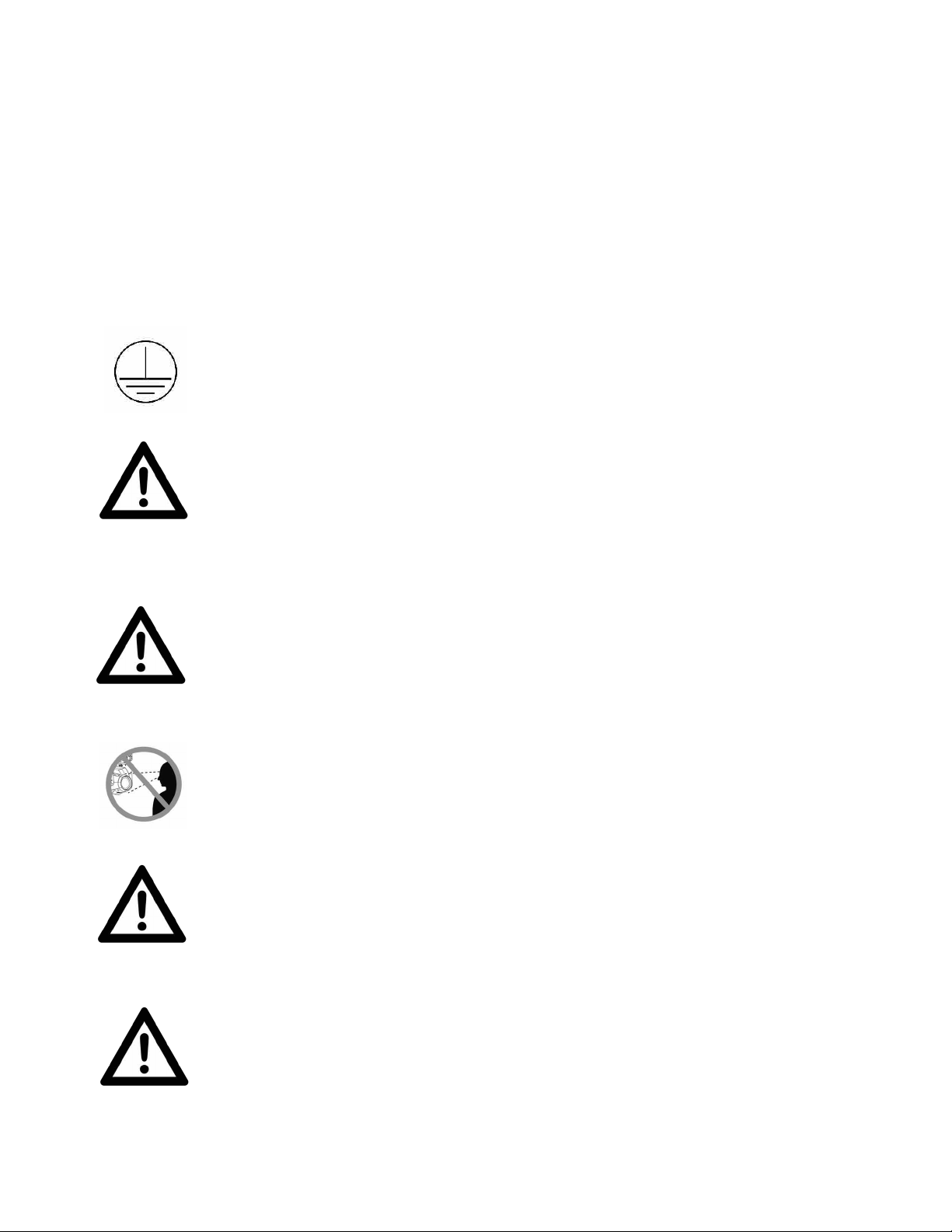
PROTECTION CLASS 1 - FIXTURE MUST BE PROPERLY GROUNDED
THERE ARE NO USER SERVICEABLE PARTS INSIDE THIS UNIT.
DO NOT ATTEMPT ANY REPAIRS YOURSELF; DOING SO WILL VOID
YOUR MANUFACTURES WARRANTY. DAMAGES RESULTING FROM
MODIFICATIONS TO THIS FIXTURE AND/OR THE DISREGARD OF
SAFETY INSTRUCTIONS AND GUIDELINES IN THIS MANUAL VOID
THE MANUFACTURES WARRANTY AND ARE NOT SUBJECT TO ANY
WARRANTY CLAIMS AND/OR REPAIRS.
DO NOT PLUG FIXTURE INTO A DIMMER PACK!
NEVER OPEN THIS FIXTURE WHILE IN USE!
UNPLUG POWER BEFORE SERVICING FIXTURE!
NEVER TOUCH FIXTURE DURING OPERATION, AS IT MAY BE HOT!
KEEP FLAMMABLE MATERIALS AWAY FROM FIXTURE!
NEVER LOOK DIRECTLY INTO THE LIGHT SOURCE!
RETINA INJURY RISK - MAY INDUCE BLINDNESS!
SENSITIVE PERSONS MAY SUFFER AN EPILEPTIC SHOCK!
ENSURE ALL CONNECTIONS AND END CAPS ARE PROPERLY
SEALED WITH A DIELECTRIC GREASE (AVAILABLE AT MOST
ELECTRICAL SUPPLIERS) TO PREVENT WATER CORROSION AND/OR
ELECTRICAL SHORT CIRCUIT.
MINIMUM DISTANCE TO OBJECTS/SURFACES
MUST BE 49.2 FEET (15 METERS)
MAXIMUM TEMP OF EXTERNAL SURFACE 185° F (85°C)
MINIMUM DISTANCE OF INFLAMMABLE MATERIALS
FROM THE SURFACE 1.6 FEET (0.5 METER)
This fixture is a sophisticated piece of electronic equipment. To guarantee a smooth
operation, it is important to follow all instructions and guidelines in this manual. Elation
Professional is not responsible for injury and/or damages resulting from the misuse of this
fixture due to the disregard of the information printed in this manual. Only qualified and/or
certified personnel should perform installation of this fixture and only the original rigging
parts (omega brackets) included with this fixture should be used for installation. Any
modifications to the fixture and/or the included mounting hardware will void the original
manufactures warranty and increase the risk of damage and/or personal injury.
M
6
SAFETY GUIDELINES
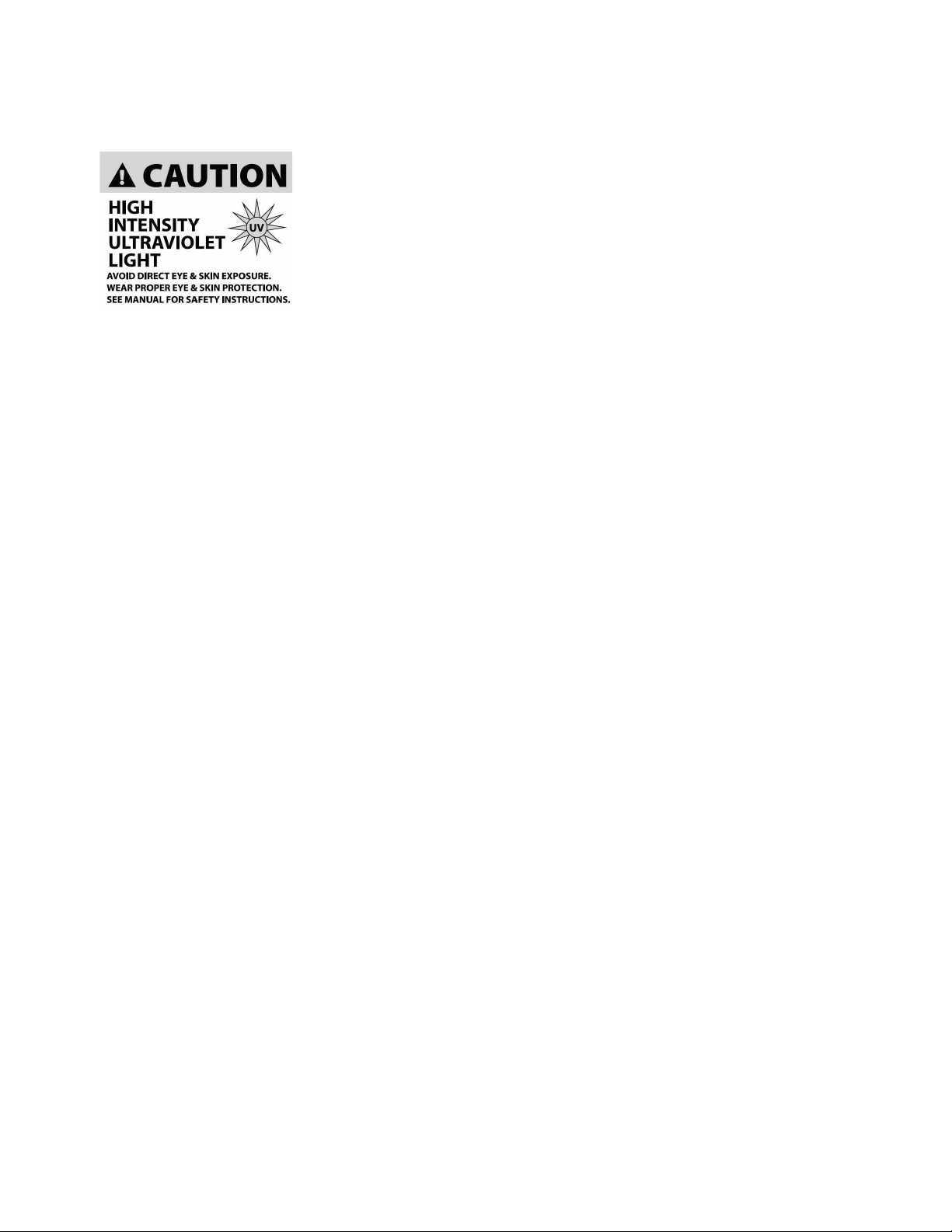
RISK GROUP 3 - RISK OF EXPOSURE TO ULTRAVIOLET UV
RADIATION! FIXTURE EMITS HIGH INTENSITY WAVELENGTH OF
ULTRAVIOLET UV LIGHT FROM THE UV COLOR FILTER. WEAR
PROPER EYE AND SKIN PROTECTION. AVOID PROLONGED
PERIODS OF EXPOSURE TO UV COLOR FILTER. AVOID
WEARING WHITE COLOR CLOTHING AND/OR USING UV PAINTS
ON SKIN. AVOID DIRECT EYE AND/OR SKIN EXPOSURE AT
DISTANCES LESS THAN 11 feet (3.3m). DO NOT OPERATE
FIXTURE WITH DAMAGED/MISSING EXTERNAL COVERS. DO NOT LOOK DIRECTLY INTO
THE UV LIGHT AND/OR VIEW UV LIGHT DIRECTLY WITH OPTICAL INSTRUMENTS THAT
MAY CONCENTRATE THE LIGHT/RADIATION OUTPUT. INDIVIDUALS SUFFERING FROM
A RANGE OF EYE CONDITIONS, SUNLIGHT EXPOSURE DIS-ORDERS, OR INDIVIDUALS
USING PHOTOSENSITIVE MEDICATION, MAY RECEIVE DISCOMFORT IF EXPOSED TO
THE ULTRAVIOLET UV LIGHT EMITTED FROM THE UV LED.
DO NOT TOUCH the fixture housing during operation. Turn OFF the power and allow
approximately 15 minutes for the fixture to cool down before serving.
DO NOT shake fixture, avoid brute force when installing and/or operating fixture.
DO NOT operate fixture if the power cord is frayed, crimped, damaged and/or if any of the
power cord connectors are damaged and do not insert into the fixture securely with ease.
NEVER force a power cord connector into the fixture. If the power cord or any of its
connectors are damaged, replace it immediately with a new one of similar power rating.
DO NOT block any air ventilation slots.
All fan and air inlets must remain clean and never blocked.
Allow approx. 6” (15cm) between fixture and other devices or a wall for proper cooling.
Always disconnect fixture from main power source before performing any type of service
and/or cleaning procedure. Only handle the power cord by the plug end, never pull out the
plug by tugging the wire portion of the cord.
During the initial operation of this fixture, a light smoke or smell may emit from the interior of
the fixture. This is a normal process and is caused by excess paint in the interior of the casing
burning off from the heat associated with the lamp and will decrease gradually over time.
Consistent operational breaks will ensure fixture will function properly for many years.
ONLY use the original packaging and materials to transport the fixture in for service.
7
DISCHARGE LAMP WARNING
This fixture is fitted with a DISCHARGE LAMP, which is highly
susceptible to damage if improperly handled. NEVER touch the lamp
with your bare hands, as the oil from your hands will shorten the life of
the lamp. NEVER move the fixture until the lamp has had ample time
to cool. DISCHARGE LAMPS are NOT covered under warranty
conditions. Avoid switching the fixture ON and OFF repeatedly in short
intervals, as this will reduce lamp life and intensity. To achieve the
intensity associated with discharge lamps, these lamps use gas sealed
in a high-pressure environment to emit a brilliant output.
Due to the high pressure involved with the construction of the lamp, it MAY EXPLODE
DURING PROLONGED EXTENSIVE USE. This risk is increased with age; added care is
encouraged when dealing with older lamps. Thus, the lamp must always be replaced at the
end of their recommended duty cycle. Extreme caution should be used when operating this
or any fixture fitted with a gas discharge lamp.
UV RADIATION NOTICE
THIS FIXTURE EMITS INTENSE UV RADIATION, WHICH IS HARMFUL
TO THE EYES AND SKIN. THE INTENSE LUMINANCE OF THE LAMP
CAN CAUSE SEVERE DAMAGE TO THE RETINA. NEVER OPERATE
THIS FIXTURE WITH ANY OF THE PROTECTIVE COVERS REMOVED.
THESE COVERS HAVE BEEN SPECIALLY DESIGNED TO SHIELD
AGAINST UV RADIATION.
LAMP REPLACEMENT
USE ONLY GENUINE ORIGINAL PHILIPS™ LAMPS. OTHER BRAND
LAMPS WILL CAUSE DAMAGE AND WILL VOID FIXTURE WARRANTY!
DISCONNECT THE MAIN POWER SUPPLY BEFORE REPLACING LAMP!
FIXTURE MUST COOL FOR 60 MINUTES BEFORE REPLACING LAMP!
NEVER TOUCH LAMP WITH BARE HANDS, ALWAYS WEAR GLOVES!
OIL FROM HANDS WILL SHORTEN LIFE OF LAMP!
MAKE SURE ALL COVERS/PANELS ARE REPLACED/SECURED BEFORE
OPERATING FIXTURE TO PREVENT ANY RISK AND/OR DAMAGE TO EYE
RETINA FROM UV RADIATION EXPOSIURE!
8

MAINTENANCE GUIDELINES
DISCONNECT POWER BEFORE PERFORMING ANY MAINTENANCE!
CLEANING
Frequent cleaning is recommended to insure proper function, optimized light output, and
an extended life. The frequency of cleaning depends on the environment in which the
fixture operates: damp, smoky or particularly dirty environments can cause greater
accumulation of dirt on the fixture’s optics. Clean the external lens surface at least every
20 days with a soft cloth to avoid dirt/debris accumulation.
NEVER use alcohol, solvents, or ammonia-based cleaners.
MAINTENANCE
Regular inspections are recommended to insure proper function and extended life.
There are no user serviceable parts inside this fixture, please refer all other service issues
to an authorized Elation service technician. Should you need any spare parts, please order
genuine parts from your local Elation dealer.
Please refer to the following points during routine inspections:
A detailed electric check by an approved electrical engineer every three months, to make
sure the circuit contacts are in good condition and prevent overheating.
Be sure all screws and fasteners are securely tightened at all times. Lose screws may fall out
during normal operation resulting in damage or injury as larger parts could fall.
Check for any deformations on the housing, color lenses, rigging hardware and rigging
points (ceiling, suspension, trussing). Deformations in the housing could allow for dust to
enter into the fixture. Damaged rigging points or unsecured rigging could cause the fixture
to fall and seriously injure a person(s).
Electric power supply cables must not show any damage, material fatigue or sediments.
NEVER remove the ground prong from the power cable.
9
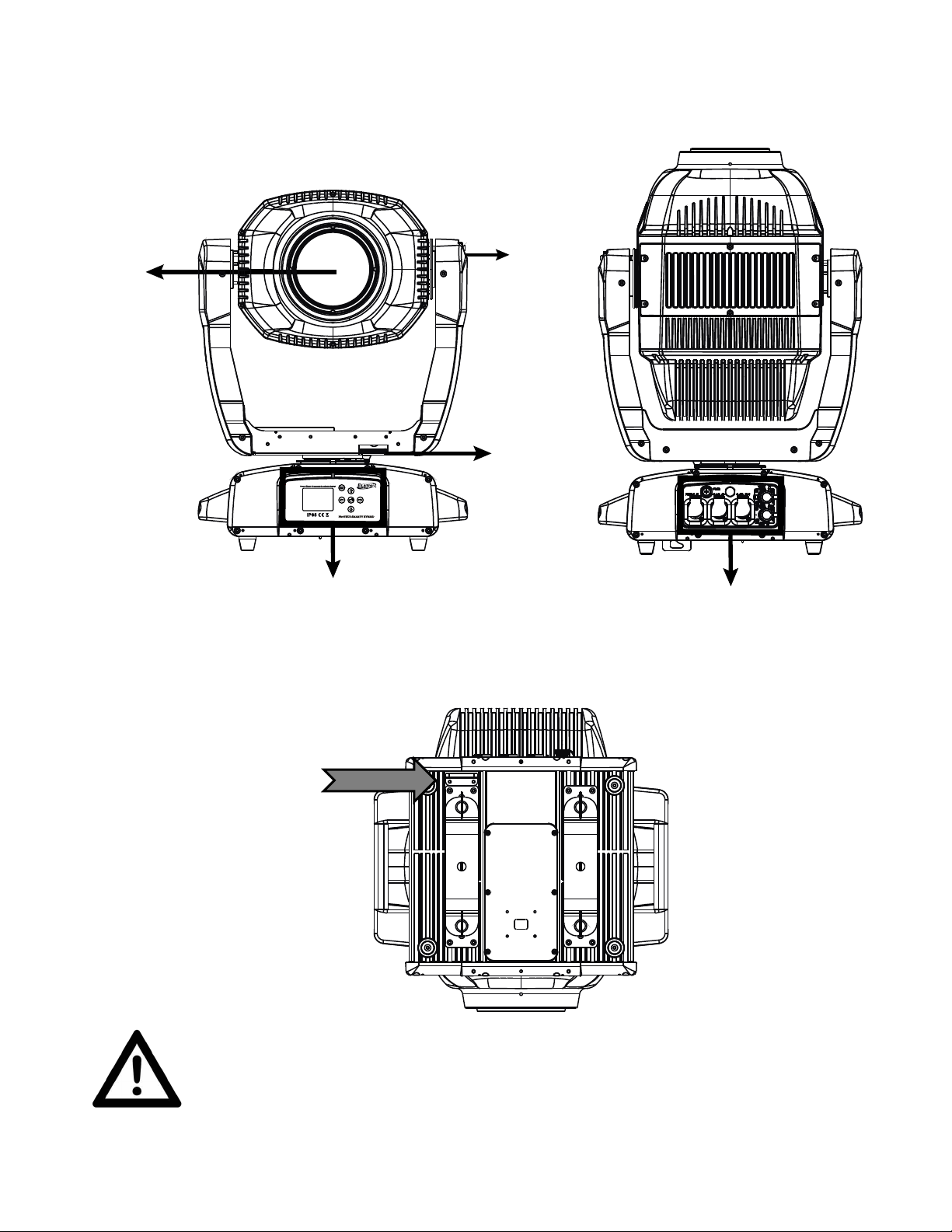
Tilt Lock
Lens
Pan Lock
Fuze
IP65 Power In
IP65 5pin DMX In/Out
System Menu Display
Menu Navigation Buttons
ALWAYS ATTACH A SAFETY CABLE WHENEVER INSTALLING THIS
DEVICE IN A SUSPENDED ENVIRONMENT TO ENSURE THE FIXTURE
WILL NOT DROP IF THE CLAMP FAILS.
SAFETY CABLE
ATTACHMEN T POINT
FIXTURE OVERVIEW
10
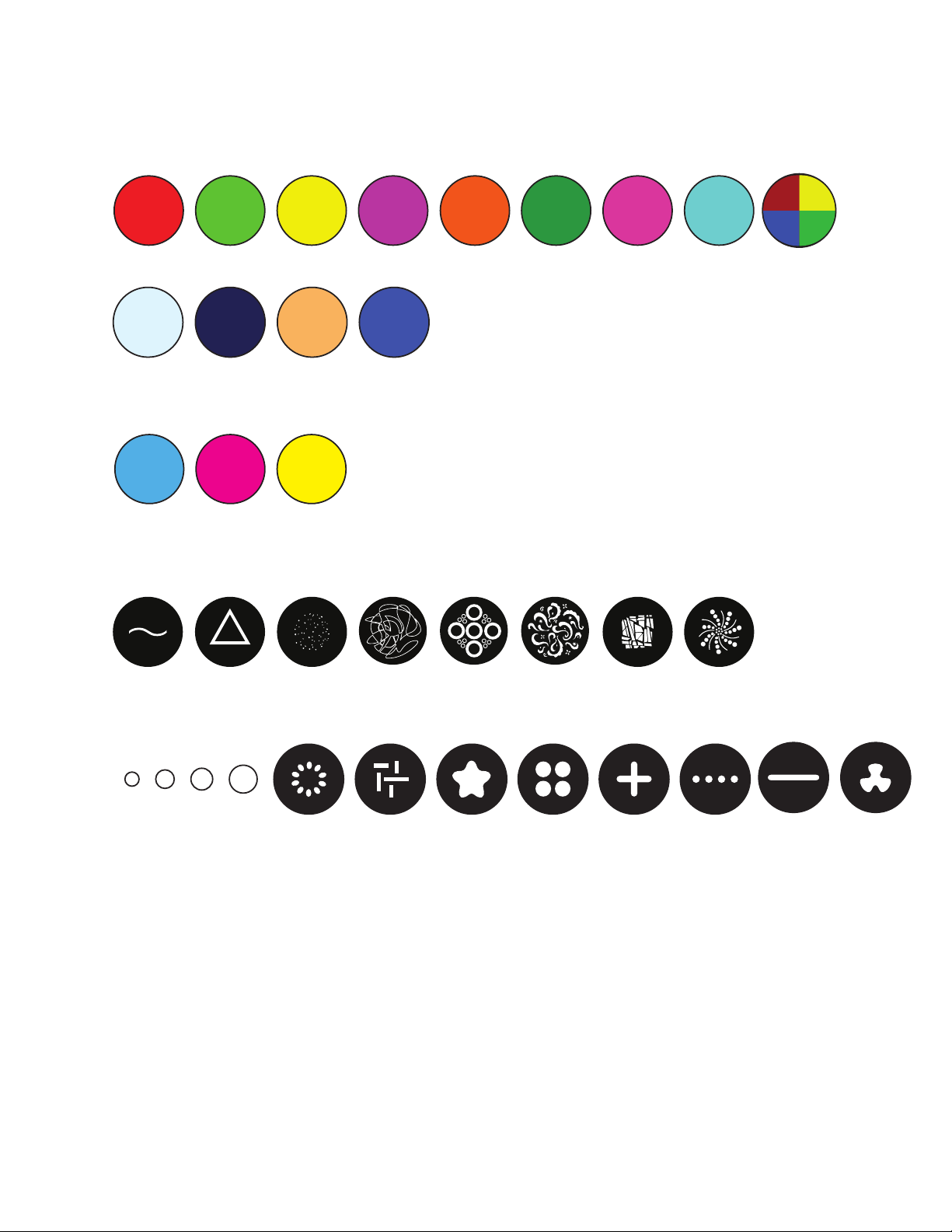
COLORS, GOBOS, ANIMATION
YMC
CTOUVCTB
CYAN MAGENTA YELLOW
1 Red 2 Green 3 Yellow 4 Magenta 5 Orange 6 Aqua 7 Pink 8 Cyan 9 RYBG
10 CTB 11 UV 12 CTO 13 Blue
COLOR FLAGS
COLOR WHEEL
INTERCHANGEABLE-ROTATING GLASS GOBO WHEEL 1
STATIC-FIXED METAL GOBO WHEEL 2
1 2 3 4 5 6 7 8
1 2 3 4 5 6 7 8 9 10 11 12
11
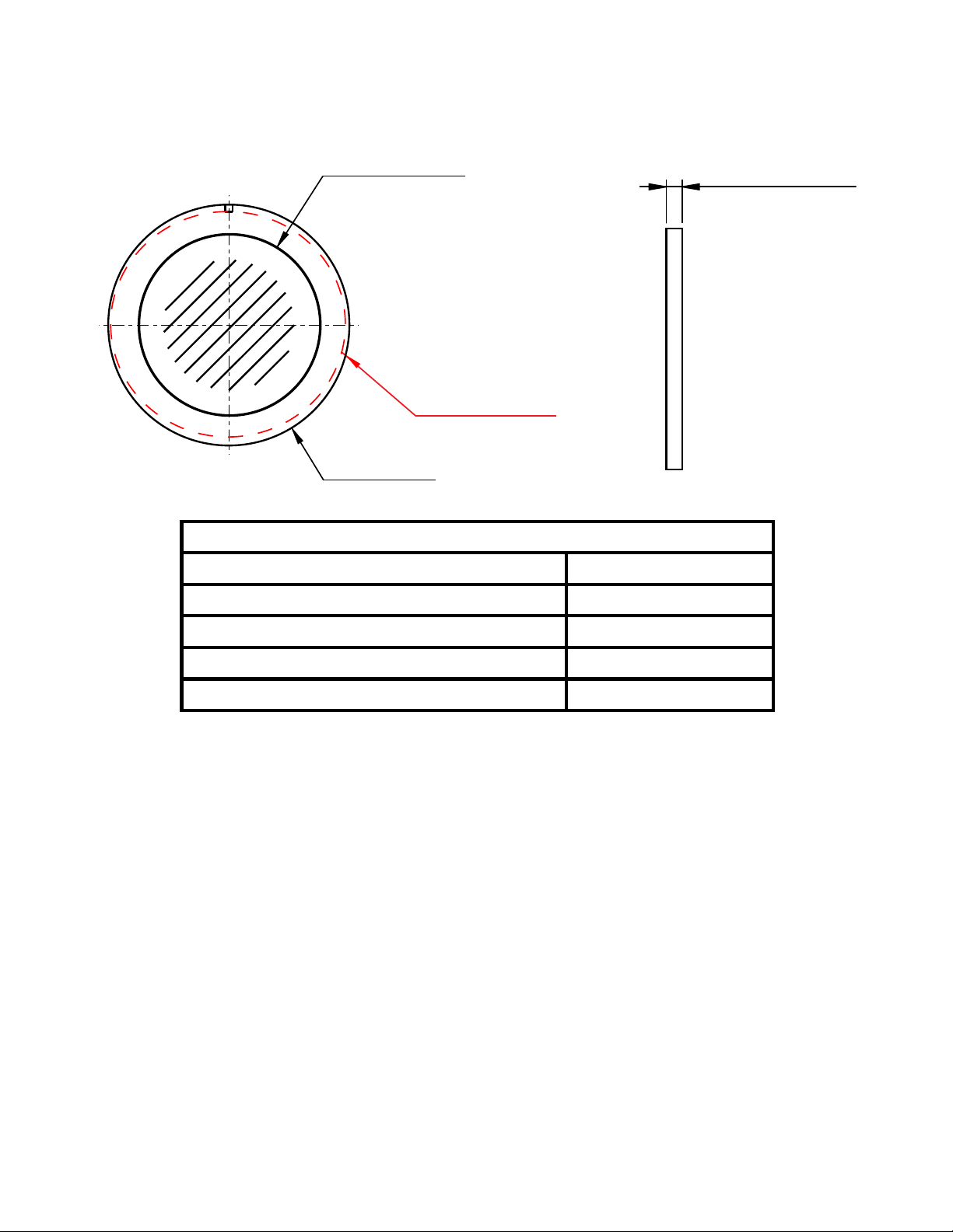
CUSTOM GOBOS
ROTATING GLASS GOBOS - WHEEL 1
Gobo O.D. (Max. Outer Diameter)
Ø 14mm -0.2~-0.3mm
Gobo I.D. (Max. Image Diameter)
Ø 7mm
Gobo Holder Diameter
Ø 14mm +0.2~+0.5mm
Gobo Thickness
Ø 1.1mm ±0.1mm
Gobo Material
BOROFLOAT
GOBO MAX I.D.
GOBO MAX O.D.
GOBO HOLDER
Ø 7.0 mm
Ø 14.0 mm +0.2 ~ +0.5mm
Ø 14.0 mm -0.2 ~ -0.3mm
THICKNESS
Ø 1.1 mm
± 0.1mm
* * * IMPORTANT NOTICE REGARDING CUSTOM GOBOS * * *
Due to the high temperature optical system, special material as listed above is
required for custom gobos. Due to varying manufacturing processes and tolerances,
it is highly recommended to provide a gobo sample and holder from the fixture to the
custom gobo vendor for accurate sizing. Extended testing of custom gobo designs is
highly recommended prior to use. Contact ELATION SERVICE for further information.
ELATION SERVICE USA - Monday - Friday 8:00am to 5:00pm PST
Voice: 323-582-3322 Fax: 323-832-9142
E-mail: support@elationlighting.com
ELATION SERVICE EUROPE - Monday - Friday 08:30 to 17:00 CET
Voice: +31 45 546 85 30 Fax: +31 45 546 85 96
E-mail: support@elationlighting.eu
12
GOBO INSTALLATION
WARNING! GOBO REPLACEMENT SHOULD ONLY BE DONE BE A TRAINED TECHNICIAN.
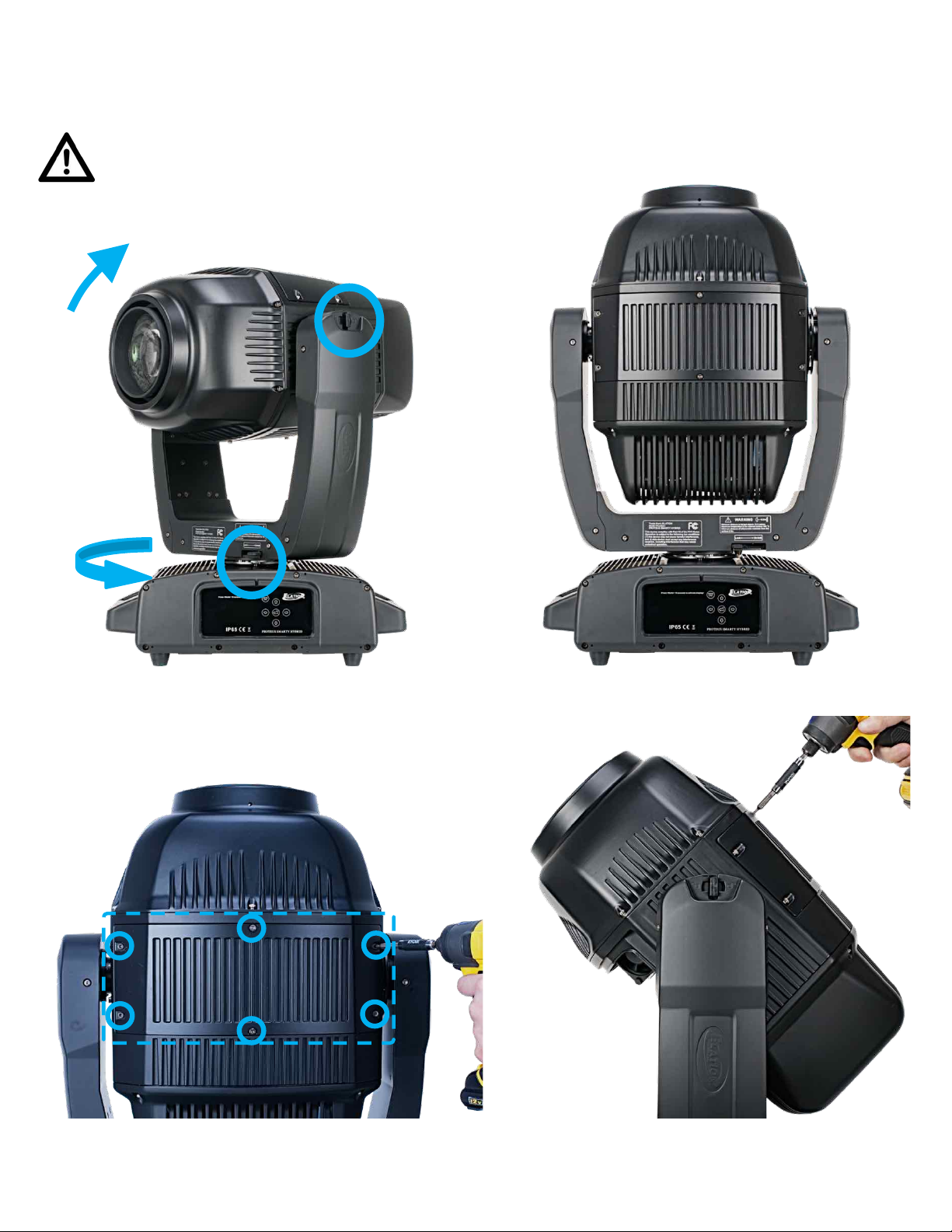
1. Turn OFF power and allow approximately 60 minutes for the fixture to cool down.
2. Before removing panels, place fixture on a stable flat surface in an INDOOR DUST FREE location.
Ensure moving head is locked into place into a neutral upright position, with both PAN and TILT locks engaged.
3. Remove front and back panels; each are secured with (6x) 3mm hex-head screws.
13
GOBO INSTALLATION [continued]
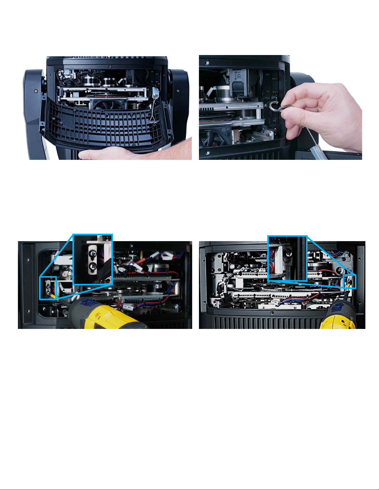
4. One at a time, gently life panels away and unclip the safety cable to remove them completely from the fixture.
5. Loosen (3x) Phillips head screws securing the GOBO Wheel Module brackets, allowing them to slide freely.
14
GOBO INSTALLATION [continued]
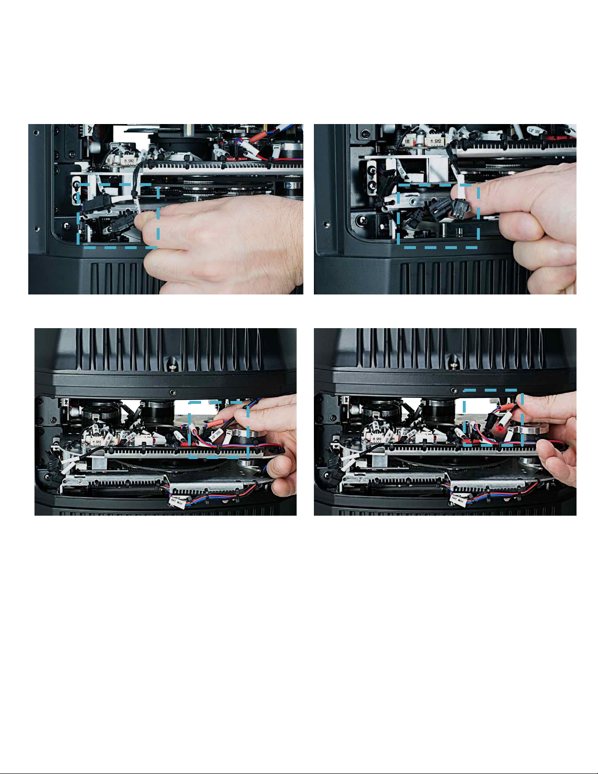
6. Before removing the GOBO Wheel Module, locate the 4 wire connectors and carefully unplug them.
(See connectors in photos 6a, 6b, 6c, and 6d) DO NOT USE FORCE TO REMOVE!
6a 6b
6c 6d
15
GOBO INSTALLATION [continued]
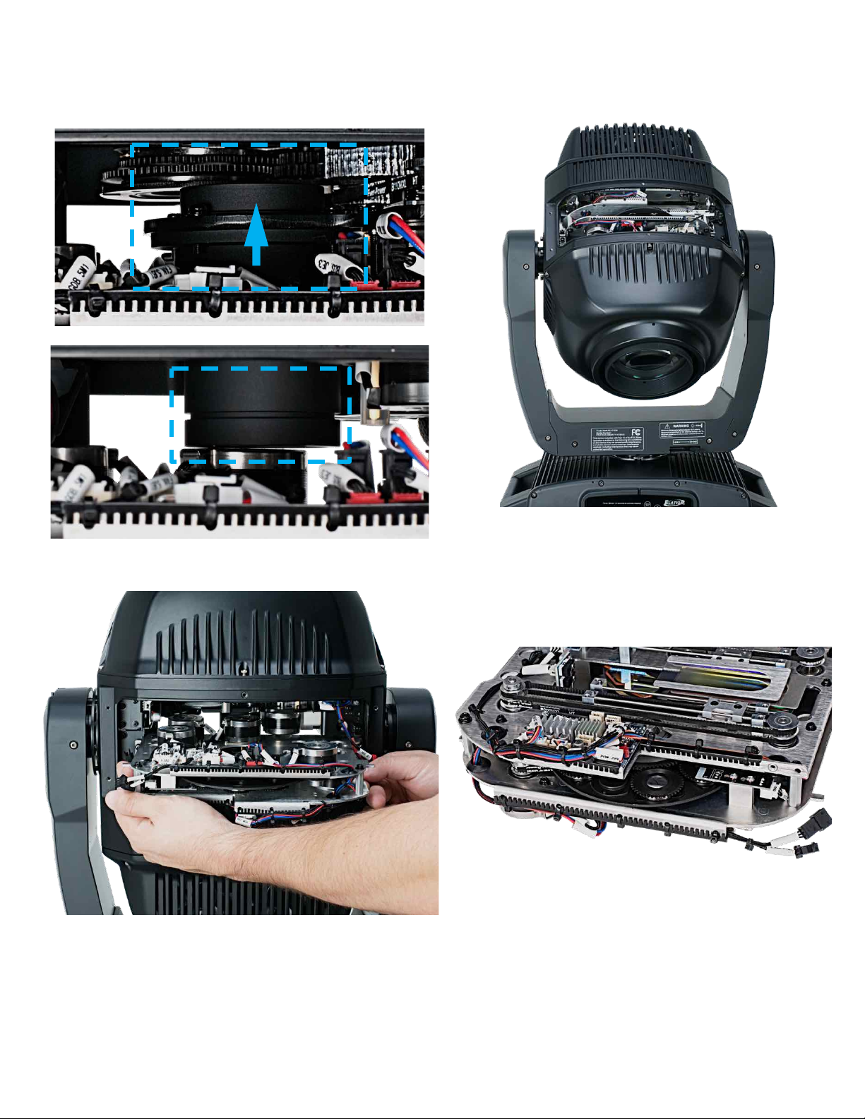
7. Lift/Push the Lens to clear GOBO Wheel Module. If it is difficult to access the Lens, it may be necessary to tilt the
head over, allowing gravity to slide the Lens out of the way.
8. Carefully grip the GOBO Wheel Module and slide it out
and away to clear the mounting rails.
9. Carefully place the GOBO Wheel Module on a stable
flat surface in an INDOOR DUST FREE location.
16
 Loading...