

Elation ProColor User Instructions
Revised 5/01
www.elationlighting.com
Los Angeles CA 90058
Elation Professional®
4295 Charter Street
User Instructions
instructed by an authorized Elation Professional
Use of a different type fuse from that which is recommended may
cause fire or electric shock and will void the manufactures warranty.
©Elation Professional® - www.elationlighting.com - ProColor™ Instruction Manual Page 2
® service technician.
Caution! There are no user serviceable parts inside this unit. Do not
Warning! To prevent or reduce the risk of electrical shock or fi re, do
not expose this unit to rain or moisture.
attempt any repairs yourself, doing so will void your manufactures war-
ranty. In the unlikely event your unit may require service please contact
your nearest Elation Professional dealer.
Safety Issues: This unit may blow a fuse if the maximum allotted load
of 7 amps is reached. If the fuse needs replacement, always replace
the fuse with same exact type that was remove, unless otherwise
E-mail: support@elationlighting.com
Customer Support: Elation Professional® provides a toll free cus-
ther instructions.
tomer support line, to provide set up help and to answer any question
should you encounter problems during your set up or initial operation.
You may also visit us on the web at www.elationlighting.com for any
comments or suggestions. Service Hours are Monday through Friday
9:00 a.m. to 5:00 p.m. Pacifi c Standard Time.
Voice: (800) 322-6337
Fax: (323) 582-3108
Unpacking: Every ProColor™ has been thoroughly tested and has
been shipped in perfect operating condition. Carefully check the ship-
ping carton for damage that may have occurred during shipping. If the
carton appears to be damaged, carefully inspect your fi xture for any
damage and be sure all equipment necessary to operate the system
has arrived intact. In the case damage has been found or parts are
missing, please contact our toll free customer support number for fur-
basic operations of this unit. The ProColor™ is a high output intelligent
color changer with a built-in frost.
Introduction: Thank you for purchasing the Elation Professional®
ProColor.
these operating instructions carefully to familiarize yourself with the
™
ProColor™ Introduction
To optimize the performance of this product, please read

• Ten Vibrant Dichroic Colored Filters Plus White
• Long Life (9000 hours) SC-150 Discharge Lamp
• Mechanical Focus and Zoom for Variable Radiation-Angles (10˚-19˚)
• Micro-Stepping Motors for Smooth Color Transitions
• DMX-512 Protocol Compatible
• Two DMX Channels
• Split Color Capable
• Fan Cooled
• Color Scroll
• Mechanical Dimmer with Frost Filter
• 0-100% Mechanical Dimmer
• Heavy Duty Mounting Yoke
• Mounts Horizontally or Vertically
©Elation Professional® www.elationlighting.com ProColor™ Instruction Manual Page 3 ©Elation Professional® www.elationlighting.com ProColor™ Instruction Manual Page 4
manual with the unit, for future reference.
ProColor ™ Features
ProColOR ™ General Instructions
Trouble Shooting............................................................12
DMX Traits............................................................................13
Warranty.....................................................................15
To optimize the performance of this product, please read these operat-
ing instructions carefully to familiarize yourself with the basic operations
of this unit. These instructions contain important safety information
regarding the use and maintenance of this unit. Please keep this
Cleaning............................................................................12
ProColor ™ Contents
Introduction..........................................................................2
Features................................................................................3
Safety Precautions...................................................................4
Controls & Functions...........................................................5
Operation..............................................................................6
DMX Addressing.............................................................7
Set-Up................................................................................7
Lamp Replacement..............................................................11
serviceable parts inside
• Never operate this unit when it’s cover is removed
• Never plug this unit in to a dimmer pack
• Always be sure to mount this unit in an area that will allow proper
ventilation. Allow about 6” (15cm) between this device and a wall
• Do not attempt to operate this unit, if it becomes damaged
• This unit is intended for indoor use only, use of this product outdoors
voids all warranties
• During long periods of non-use, disconnect the unit’s main power
• Always mount this unit in safe and stable matter
• Power cords should be routed so they are not likely to be walked on,
pinched by items placed upon or against them.
• Cleaning -The fixture should be cleaned only as recommended by
the manufacturer. See page 12 for cleaning details
• Heat -The appliance should be situated away from heat sources
such as radiators, heat registers, stoves, or other appliances
(including amplifiers) that produce heat.
• The fixture should be serviced by qualified service personnel when:
A. The power-supply cord or the plug has been damaged.
B. Objects have fallen, or liquid has been spilled into the unit.
C. The unit has been exposed to rain or water.
• Do not remove the cover under any conditions. There are no user
ProColor™ Safety Precautions
• This unit may blow a fuse if the maximum allotted load of 10 amps
(220v = 5 amps) is reached. If the fuse needs replacement, always
replace the fuse with same exact type that was remove. Use of a
different type fuse from that which is recommended may cause fire or
electric shock and will void the manufactures warranty
• To reduce the risk of electrical shock or fi re, do not expose this unit
rain or moisture
• Do not spill water or other liquids into or on to your unit
• Be sure that the local power outlet match that of the required voltage
for your unit
• Do not attempt to operate this unit if the power cord has been frayed
or broken
• Do not attempt to remove or break off the ground prong from the
electrical cord. This prong is used to reduce the risk of electrical
shock and fi re in case of an internal short
• Disconnect from main power before making any type of connection
fi xture. Use the Supplied I.E.C. cord to supply main power to your
g
fi xture. Be sure the main power matches that of the required power
of your fi xture.
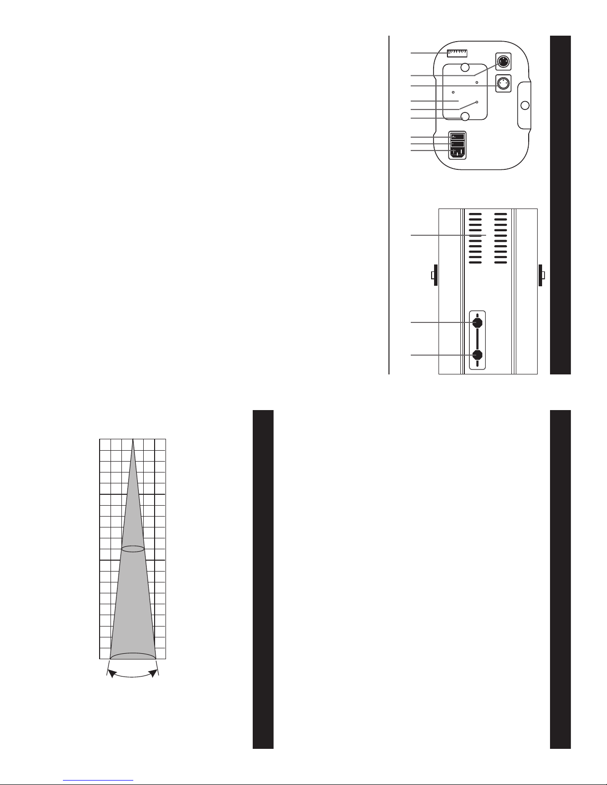
10.Fan Vent - Keep these cooling vent clean and never block them.
11.Focussing Adjustments - Use these adjustments to adjust both the
sharpness and diameter of the beam.
3. XLR Output Jack - This jack is used to send the incoming DMX
signal to another DMX fi xture.
4. Lamp Socket Assembly Plate - This plate accesses the lamp socket
assembly.
5. Lamp Optimization Screws - These three screws are spring loaded
and are used to optimize the lamp. Use these three screws to
center the lamp in the refl ector.
6. Thumb Screw - These two thumb screw hold the assembly plate
into place.
7. Main Power Switch - this switch control main power to the unit.
8. Fuse Holder - This houses the safety fuse. Be sure to always replace
with the exact same type, unless otherwise instructed by authorized
American DJ service technician.
9. Power Input- This male I.E.C. jack is used to feed main power to the
1. Dip Switches - These switches are used to set the DMX address.
Each switch corresponds to a specifi c value based on binary code.
See page 6 for a detailed explanation of DMX binary code.
2. XLR Input Jack - This jack is used to accept an incoming DMX
signal.
187654329
1 2 3 4 5 6 7 8 9 10
ON
FUSE
specifi c distance and beam diameter.
Beam opening (m)
.25
©Elation Professional® www.elationlighting.com ProColor™ Instruction Manual Page 6©Elation Professional® www.elationlighting.com ProColor™ Instruction Manual Page 5
.5
1
0
.25
.5
0
1
10∞ radiation an
36
le
111110
each fixtures DMX traits with a standard DMX 512 controller such
as the Elation Professional® Show Designer™ or DMX Operator.
This illustration represents the approximate intensity associated with a
ProColor™ Beam Patch
7. For longer cable runs (more than a 100 feet) use a terminator on
the last fixture in you DMX chain.
follow the dip switch settings on page 14.
6. For help operating in DMX operation consult the manual included
with your DMX controller.
3. Use the controller’s faders to control the various DMX fixture traits.
4. This will allow you to create custom programs.
5. When using a DMX controller and setting up for DMX operation
2. To control your fixture in DMX mode, follow the unit set-up proce-
dures beginning on page 8 as well as the set-up specifications
that are included with your DMX controller.
color change operation and channel two control all other functions
such as shutter and frost. Please refer to page 14 for a detailed
description of the DMX traits.
Operating through a DMX controller allows the freedom to create
unique programs tailored to one’s individual needs.
1. The ProColor™ uses two DMX channel. Channel one controls the
Universal DMX Control: This function will allow you to control
ProColor™ Operation ProColor™ Controls and Functions
727.5 2910 Max LUX
10.28
Diameter in Meters0 1.08.54
Distance in Meters
˚
™
 Loading...