

Elation Power Spot 700 User Manual
Please Note: This is a pre-release user manual, some images are not correct and some specifications may
User Manual
change!

Power Spot 700™
©Elation Professionals® Los Angeles, Ca. - wwww.ElationLighting.com - Page 2

Power Spot 700™
Table of Contents
Introduction.............................................................................................................5
Unpacking.........................................................................................................5
Customer Support ............................................................................................5
Discharge Lamp Precautions............................................................................6
Safety Instructions..................................................................................................7
1 Fixture Layout .........................................................................................................8
2 Preparation and Installation.................................................................................11
2.1 Mounting.........................................................................................................13
2.1.1 Clamps.................................................................................................13
2.1.2 Mounting Plate.....................................................................................12
2.2 Rigging the Power Spot 700™ .......................................................................15
2.3 Connections....................................................................................................15
2.3.1 Power Supply.......................................................................................13
2.3.2 DMX-512 Pin Configuration .................................................................13
2.4 DMX-512 ........................................................................................................15
2.5 Data Cable Requirements ..............................................................................15
2.6 Special Note...................................................................................................15
2.7 Line Termination.............................................................................................15
2.8 MX Pin Conversion.........................................................................................15
2.9 Fuse Requirements ........................................................................................15
2.10 Transporting & Handling.................................................................................15
3 Menu Field .............................................................................................................16
3.1 Setting the DMX - Address (D001) ................................................................. 18
3.2 Test Menu (TEST)..........................................................................................20
3.3 Lamp On/Off (LAMP)......................................................................................18
3.4 Reset (RESE).................................................................................................21
3.5 Running Time (lamp/unit) (TIME) ...................................................................21
3.6 Invert Pan Movement (RPAN)........................................................................19
3.7 Invert Tilt Movement (RTLT)...........................................................................22
3.8 DMX Mode......................................................................................................22
3.9 Special Functions (SPEC)..............................................................................22
3.9.1 Manual Drive (MANU)..........................................................................22
3.9.2 Lamp On (automatic) (LAAU)...............................................................23
3.9.3 Lamp Off (via DMX).............................................................................24
©Elation Professionals® Los Angeles, Ca. - wwww.ElationLighting.com - Page 3

Power Spot 700™
3.9.4 DMX Input (DLOF)...............................................................................22
3.9.5 LED Display (DISP).............................................................................24
3.9.6 Fixture Temperature (TEMP)...............................................................25
3.9.7 Fan Control (FANS) ............................................................................26
3.9.8 Adjustments and Calibrations (ADJU).................................................26
3.9.9 Default Settings (DFSE).......................................................................27
3.9.10 Feedback (FEED) ................................................................................28
3.9.11 Fault Corrections (EFLD) ....................................................................28
3.10 Error and Information Messages ....................................................................28
4 Operating Modes...................................................................................................28
4.1 Universal DMX Control...................................................................................27
4.2 Stand Alone (Sound Active)............................................................................27
4.3 Master-Slave ..................................................................................................28
5 DMX Channel Selection (DMX Protocol)...............................................................29
6 Lamp Change ........................................................................................................33
6.1 Safety Regulations..........................................................................................42
6.2 Realize the Lamp Change..............................................................................42
7 Fuse Replacement ................................................................................................35
8 Change a Gobo......................................................................................................45
8.1.1 Safety Regulations...............................................................................45
8.1.2 Realize the Gobo Change....................................................................45
9 Maintenance and Cleaning the Power Spot 700™ .............................................47
9.1 Safety Regulations..........................................................................................47
9.2 Circumference and Interval.............................................................................47
9.3 Cleaning the Optical System ..........................................................................48
10 Technical Specification........................................................................................40
11 Warranty ................................................................................................................41
12 Dimensions............................................................................................................43
13 Index.......................................................................................................................44
©Elation Professionals® Los Angeles, Ca. - wwww.ElationLighting.com - Page 4

Power Spot 700™
INTRODUCTION: Congratulations, you have just purchased one of the most innovative
and reliable lighting fixtures on the market today! The Power Spot 700™, has been
designed to perform reliably for years when the guidelines in this booklet are followed.
Please read and understand the instructions in this manual carefully and thoroughly before
attempting to operate this unit. These instructions contain important information regarding
safety during use and maintenance.
UNPACKING: Thank you for purchasing the Power Spot 700™ by Elation Professional®.
Every Power Spot 700™ has been thoroughly tested and has been shipped in perfect
operating condition. Carefully check the shipping carton for damage that may have
occurred during shipping. If the carton appears to be damaged, carefully inspect your unit
for damage and be sure all accessories necessary to operate the unit have arrived intact.
In the event damage has been found or parts are missing, please contact our customer
support team for further instructions. Please do not return this unit to your dealer without
first contacting customer support at the number listed below.
CUSTOMER SUPPORT: Elation Professional® provides a customer support line, to
provide set up help and to answer any question should you encounter problems during
your set up or initial operation. You may also visit us on the web at
www.elationlighting.com for any comments or suggestions. For service related issue
please contact Elation Professional®. Service Hours are Monday through Friday 9:00 a.m.
to 5:00 p.m. Pacific Standard Time.
Voice: (866) 245-6726
Fax: (323) 582-3108
E-mail: support@elationlighting.com
Forum: www.ElationLighting.com/forum/
Warning! To prevent or reduce the risk of electrical shock or fire, do not expose this unit to
rain or moisture.
Caution! There are no user serviceable parts inside this unit. Do not attempt any repairs
yourself, doing so will void your manufactures warranty.
Please do not discard the shipping carton in the trash. Please recycle whenever possible.
©Elation Professionals® Los Angeles, Ca. - wwww.ElationLighting.com - Page 5
Power Spot 700™
WARRANTY REGISTRATION: The Power Spot 700™ carries a two year (730 days)
limited warranty. Please fill out the enclosed warranty card to validate your purchase. All
returned service items whether under warranty or not, must be freight pre-paid and
accompany a return authorization (R.A.) number. The R.A. number must be clearly written
on the outside of the return package. A brief description of the problem as well as the R.A.
number must also be written down on a piece of paper and included in the shipping
container. If the unit is under warranty, you must provide a copy of your proof of purchase
invoice. Items returned without a R.A. number clearly marked on the outside of the
package will be refused and returned at cutomers exspence. You may obtain a R.A.
number by contacting customer support at (323) 582-3322.
DISCHARGE LAMP WARNING: This fixture is fitted with a discharge
lamp, which is highly susceptible to damage if improperly handled.
Never touch the lamp with your bare hands, as the oil from your hands
will shorten lamp life. Also, never move the fixture until the lamps have
had ample time to cool. Remember, lamps are not covered under
warranty conditions.
This fixture emits intense UV radiation, which is harmful to the eyes and skin. The intense
luminance of the lamp can cause severe damage to the retina. Never operate this fixture
with the protective covers removed, these covers have been specially designed to shield
against UV radiation.
Epileptic Warning: Those suffering from epilepsy should avoid looking directly into the
lamp at all times.
Avoid switching the fixture on and off repeatedly in short intervals, as this will reduce lamp
life and intensity.
To achieve the intensity associated with discharge lamps, these lamps use a gas sealed in
a high-pressure environment to emit a brilliant output. Due to the high pressure involved
with the construction of the lamp, the lamp may explode during prolonged extensive use.
This risk is increased with age; added care is encouraged when dealing with older lamps.
Thus, lamp should always be replaced at the end of their recommended duty cycle.
©Elation Professionals® Los Angeles, Ca. - wwww.ElationLighting.com - Page 6

Power Spot 700™
Extreme caution should be used when operated this or any fixture fitted with a gas
discharge lamp.
Never open this fixture while in use!
During the initial operation of this fixture, a light smoke or smell may emit from the interior
of the fixture. This is a normal process and is caused by excess paint in the interior of the
casing burning off from the heat associated with the lamp.
©Elation Professionals® Los Angeles, Ca. - wwww.ElationLighting.com - Page 7
Power Spot 700™
Safety Instructions
The Power Spot 700™ is an extremely sophisticated piece of
electronic equipment. To guarantee a smooth operation, it is
important to follow the guidelines in this manual. The
manufacturer of this device will not accept responsibility for
damages resulting from the misuse of this fixture due to the
disregard of the information printed in this manual.
1. Always be sure that the fan and the air inlets remain clean and are never
blocked. Allow about 6” (15cm) between this fixture and other devices or a wall to
allow for proper cooling.
2. Never touch the fixture during normal operation. This can cause severe personal
injuries and/or damage to the fixture.
3. Be sure to unplug the POWER SPOT 700™ from the power outlet before
performing any service related issues.
4. Lamp Replacement; Allow at least 30 minutes after disconnecting main power
before you open the POWER SPOT 700™. To prevent personal injury, never
touch the lamp if you are not absolutely sure it has cooled.
5. Never look directly into the lamp beam. You risk injury to your retina, which may
induce blindness.
6. Be sure to track and record the lamp running time. The lamp should be changed
at the end of the specified lamp life, regardless of lamp output. You may also
have to change the lamp if it shows any deformations or damage. The same is
with all glass components, color filters, lenses and mirrors.
7. For safe operation, follow the Installation guide described in chapter two of this
manual. Operating the POWER SPOT 700™ without suited safety aids such as
safety cables or clamps can increase the risk of damage and/or personal injury.
8. Installation should only be performed by qualified and certified personal.
9. When mounting this fixture, use only the original rigging parts included with this
fixture. Any structural modification will void the original manufactures warranty
and may increase the risk of damage and/or personal injury.
10. To reduce the risk of fire or shock, do not expose this unit to rain or moisture.
11. Do not attempt to operate this fixture if the power cord is frayed or damaged.
©Elation Professionals® Los Angeles, Ca. - wwww.ElationLighting.com - Page 8
Power Spot 700™
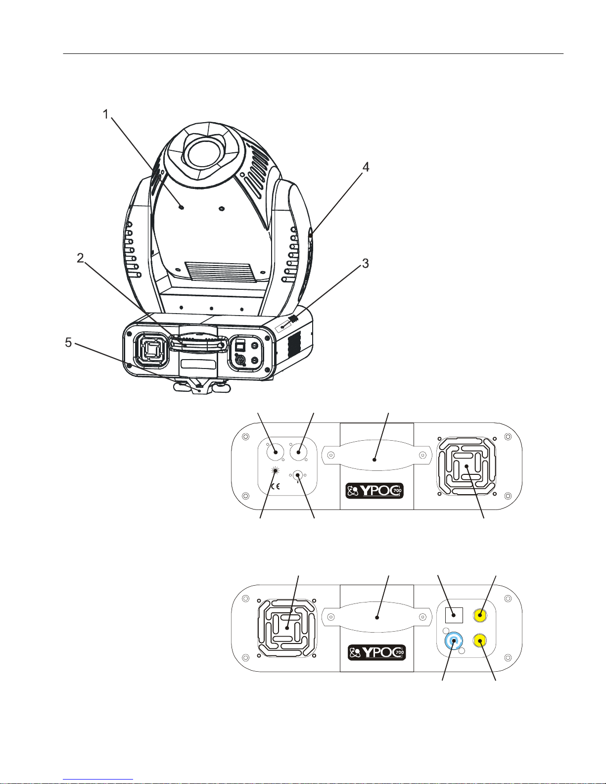
1. FIXTURE LAYOUT
1. Moving Head
2. Carrying Handles
3. LED Menu Display
4. Head Tilt Lock
5. Omega Clamp
6. Software-Update
Connector
7. Microphone
Sensitivity
8. DMX- Input
9. DMX- Output
10. Fan (air inlet/outlet)
11. Electronics Fuse
12. Main Power Supply
(Powercon)
13. Power On/Off
14. Lamp Fuse
15. Carrying Handles
8 9
DMX IN DMX OUT
1.Ground
2.Dat a -
3.Dat a +
MaxMin
Mic Sensitivit y
Software Update
7
10
15
6
15
13 14
10
La mp
PO WER
Fuse
0
1
T 10A @ 115 V~
T 5A @ 2 30 V~
Power Input: 90 - 2 6 0 VAC, 50/ 60 Hz
T 2A @ 115 V~
T 1A @ 230 V~
Ele c tro nic
Fuse
©Elation Professionals® Los Angeles, Ca. - wwww.ElationLighting.com - Page 9
12
11

Power Spot 700™
1.
Head Assembly –
The head assembly consist of the main output lens, and either
the standard or CMY control module.
2.
Carrying Handle –
The fixtures includes two built-in carrying handles. Be sure to
always handle the fixture by the built-in carrying handles. Never lift or carry the
fixture by the head or retaining arms as this could cause serious damage to the
fixture and void your manufactures warranty.
3.
4-Segment Menu Display –
This display details all the various menu functions.
See page XX for a detailed breakdown of the operating menu.
4.
Tilt Lock –
This lock will hold the head assembly in place for transportation
and/or service. Depress the lock button to lock and unlock the head assembly.
The head will lock in a 90˚ or 45˚ orientation. Always be sure to unlock the head
assembly before applying main power to the unit. Failure to do so will result in a
start-up error and may damage the unit.
5.
Omega Clamp -
This fixture uses a cam-lock clamp system that allows a quick
and efficient means to secure a clamp to the unit. To attach a clamp to the unit,
attach a clamp that is rated to handle the weight of the unit to your omega clamp.
After a clamp has been attached to the omega clamp, attach the cam locks to the
designated position on the bottom of your unit. Lock the cam locks into position by
turning the wing nuts 90°. See page XX for proper clamp mounting and assembly.
6.
Firmware Connection –
This connector is for use by an authorized technician
only. This connector is used to upgrade the operating software and to test the
fixture.
7.
Microphone Sensitivity Adjustment Knob –
This knob is used to adjust the
frequency sensitivity of the internal microphone when operating in “audio” mode.
When the knob is turned counter-clockwise the unit is less sensitive to sound.
When the knob is turned clockwise the unit is more sensitive sound.
8.
DMX Input Jack –
This 3-Pin XLR jack is used to receive an incoming DMX
signal.
9.
DMX Output Jack –
This 3-Pin XLR jack is used to send an outgoing DMX
signal. For best results this jack should be terminated if it is the last fixture in a
DMX daisy-chain (see termination on page 14).
©Elation Professionals® Los Angeles, Ca. - wwww.ElationLighting.com - Page 10

Power Spot 700™
10.
Internal Cooling Fan –
speed fans mounted in the base to aid in the cooling process. These fans are
designed to vary their velocity at different operating temperatures. When the
fixture reaches a predetermined internal operating temperature the fans function
at high speeds. The higher speeds provide better cooling associated with higher
operating temperatures during long use. When the fixture is operating at a lower
temperature the fans operate at low speed. Be sure to keep all vents clean,
blocked cooling vents can shorten lamp life and reduce the fixtures reliability. For
more information on the fan functions see page 23, section 3.9.7.
11.
Electronics Fuse Holder –
operation). Never defeat this fuse, this fuse is designed to protect the electronics
in the event of severer power fluctuations. In the event of fuse failure, always be
sure to replace this fuse with an exact match unless otherwise instructed by an
authorized Elation technician.
12.
Powercon Connector –
Neutrik Powercon adapter included with your fixture. This jack provides main
power to your fixture.
13.
Power Switch –
14.
Lamp Fuse Holder –
Never defeat this fuse, this fuse is designed to protect the lamp in the event of
severer power fluctuations. In the event of fuse failure, always be sure to replace
this fuse with an exact match unless otherwise instructed by an authorized Elation
technician.
15.
Mode Select Button –
menu and on-board programming functions.
16.
Enter Select Button –
when working in the fixture’s operating system.
This fixture is equipped with two high-velocity variable
This housing holds a 250v/2A GMA fuse (120v
This power jack is designed to be used only with the
The switch is used to control main power to fixture’s electronics.
This housing holds a 250v/10A GMA fuse (120v operation).
This button is used to access the fixture’s main system
This button is used to select and confirm a menu function
©Elation Professionals® Los Angeles, Ca. - wwww.ElationLighting.com - Page 11

Power Spot 700™
17.
Down Select Button –
through the system menu.
18.
Up Select Button -
the system menu.
This button is used to scroll backwards when navigating
This button is used to scroll forward when navigating through
©Elation Professionals® Los Angeles, Ca. - wwww.ElationLighting.com - Page 12
Power Spot 700™
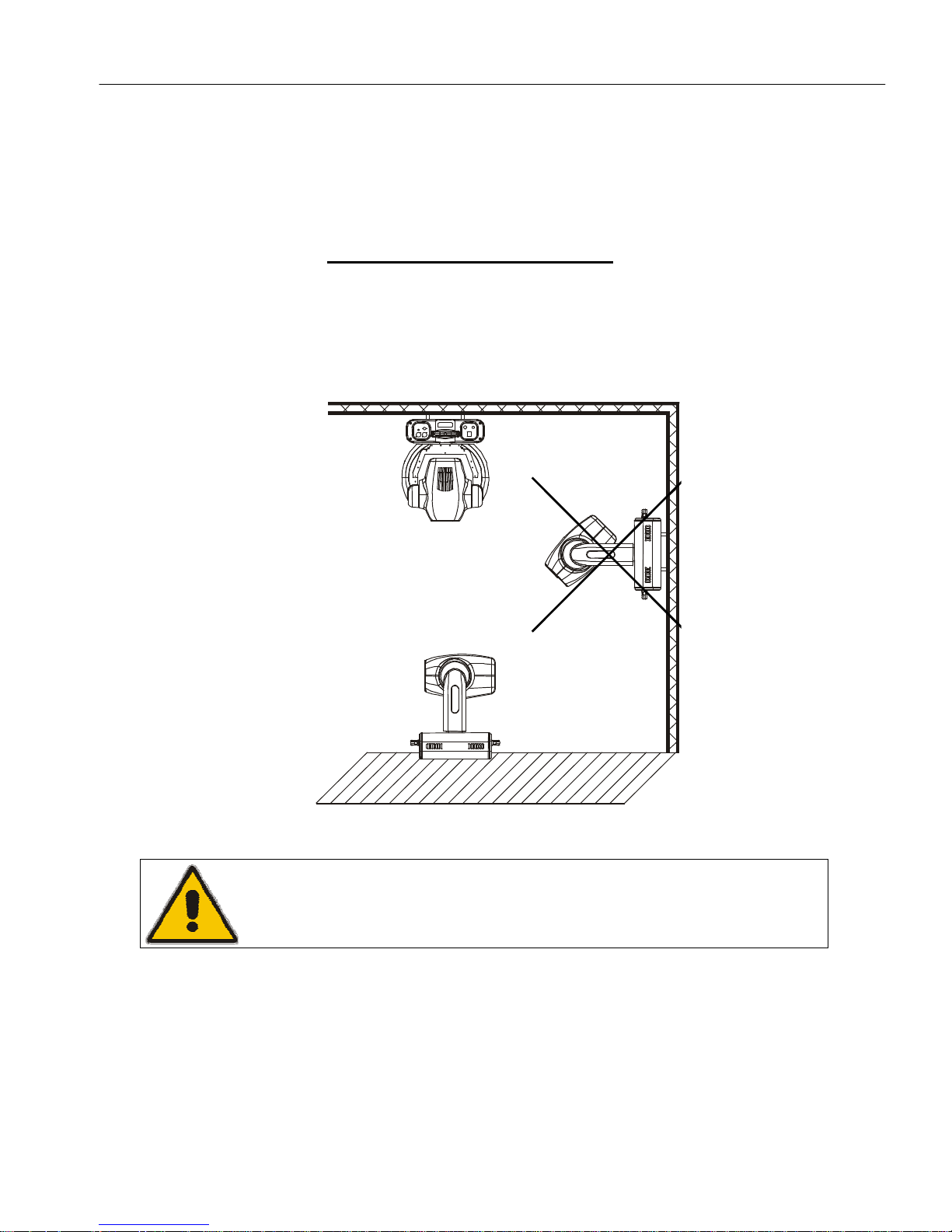
1. Preparation and Installation
1.1 Mounting
The POWER SPOT 700™ is fully operational in two different mounting positions,
hanging upside from a ceiling or set on a flat level surface. To avoid internal
damage to the unit, never mount the unit on its side
as illustrated below. Be sure
this fixture is kept at least 0.5m away from any flammable materials (decoration
etc.). Install a safety cable that can hold at least 10 times the weight of the fixture.
Never use the carrying handles for secondary attachment.
Refer to regulations BGV C1 (formerly VBG 70) and DIN VDE
To ensure proper installation, only qualified staff should
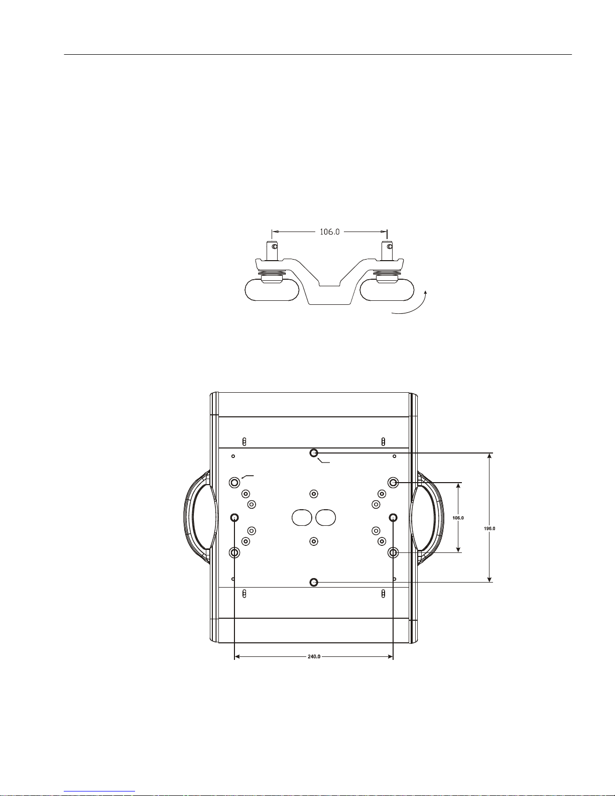
2.1.1 Clamps
The POWER SPOT 700™ has been designed to hold multiple clamps to the
bottom of the unit in several different orientations. Always use an appropriately
rated clamp to mount this unit to truss. Refer to the printed instructions on the
©Elation Professionals® Los Angeles, Ca. - wwww.ElationLighting.com - Page 13
0711-217 for proper installation in Europe
attempt installation.
Power Spot 700™
bottom of the fixture for proper clamp installation.
a) Cam lock System: This system allows a quick and efficient means to
secure a clamp to the unit. To attach a clamp to the unit, attach a clamp
that is rated to handle the weight of the unit to your cam lock. After a clamp
has been attached to the cam lock, attach the cam locks to the designated
position on the bottom of your unit. Lock the cam locks into position by
turning the wing nuts 90°.
b) Be sure to always use two cam locks mounted to the bottom of unit to
90°
ensure safe truss mounting (each two opposite threads max. M10x20).
4x M10x20mm
4x Camlock
©Elation Professionals® Los Angeles, Ca. - wwww.ElationLighting.com - Page 14

Power Spot 700™
2.2 Secure the POWER SPOT 700™
Regardless of the rigging option you choose for your POWER SPOT 700™ always
be sure to secure your fixture with a safety cable. The fixture provides a built-in
rigging point for a safety cable on the underside of the fixture, be sure to use this
point and never secure a safety cable to a carrying handle.
2.3 Connections
2.3.1 Power supply
Electronic ballast with:
90~260 Volts, 50~60 Hz,
Grounded contact type plug – Neutrik Powercon
Connected load 780W <=> 3.8A (blind current compensation).
NOTE: The universal power supply will accept any voltage source as detailed
above without any type of internal or user modifications.
2.3.2 DMX-512
3-Pin XLR Input/Output. [+] = Pin 3 / [-] = Pin 2 / [Ground] = Pin 1
DMX-512: DMX is short for Digital Multiplex. This is a universal protocol used
by most lighting and controller manufactures as a form of communication
between intelligent fixtures and controllers. A DMX controller sends DMX data
instructions from the controller to the fixture. DMX data is sent out as serial
data that travels from fixture to fixture via the DATA “IN” and DATA “OUT”
XLR terminals located on all DMX fixtures (most controllers only have a DATA
“OUT” terminals). DMX Linking: DMX is a language allowing all makes and
models of different manufactures to be linked together and operate from a
single controller, as long as all fixtures and the controller are DMX compliant.
To ensure proper DMX data transmission, when using several DMX fixtures
try to use the shortest cable path possible. The order in which fixtures are
connected in a DMX line does not influence the DMX addressing. For
example; a fixture assigned a DMX address of 1 may be placed anywhere in a
DMX line, at the beginning, at the end, or anywhere in the middle. Therefore,
the first fixture controlled by the controller could be the last fixture in the chain.
When a fixture is assigned a DMX address of 1, the DMX controller knows to
©Elation Professionals® Los Angeles, Ca. - wwww.ElationLighting.com - Page 15
Power Spot 700™
send DATA assigned to address 1 to that fixture, no matter where it is located
in the DMX chain.
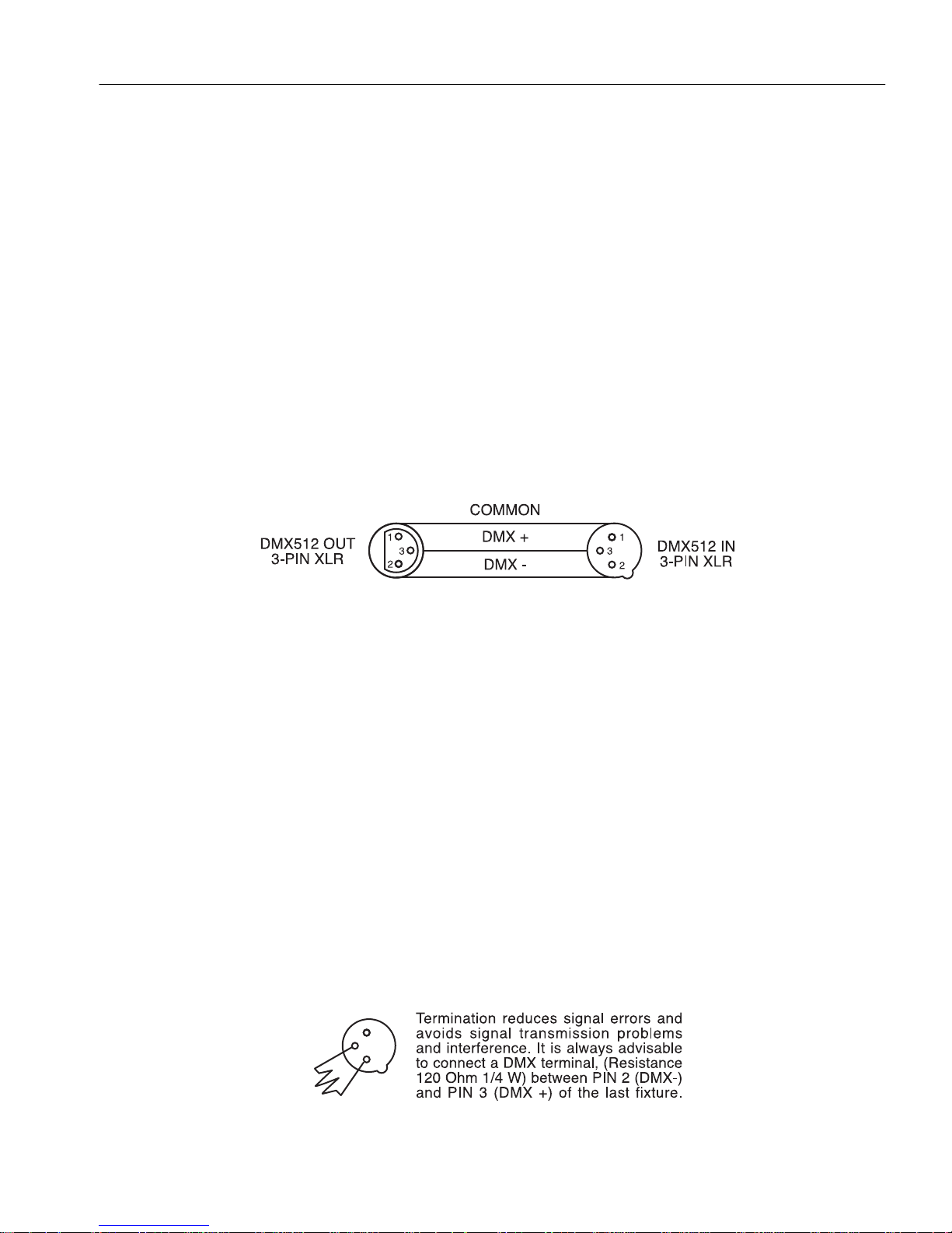
2.4 Data Cable (DMX Cable) Requirements (For DMX and Master/Slave Operation):
The POWER SPOT 700™ can be controlled via DMX-512 protocol. The POWER
SPOT 700™ is a 21 channel DMX fixture. The DMX address is set electronically
using the controls on the side panel of the fixture. Your fixture and your DMX
controller require a standard 3-pin XLR connector for data input and data output
(Figure Below). If you are making your own cables, be sure to use standard two
conductor shielded cable (This cable may be purchased at almost all professional
sound and lighting stores). Your cables should be made with a male and female
XLR connector on either end of the cable. Also remember that DMX cable must be
daisy chained and can not be split.
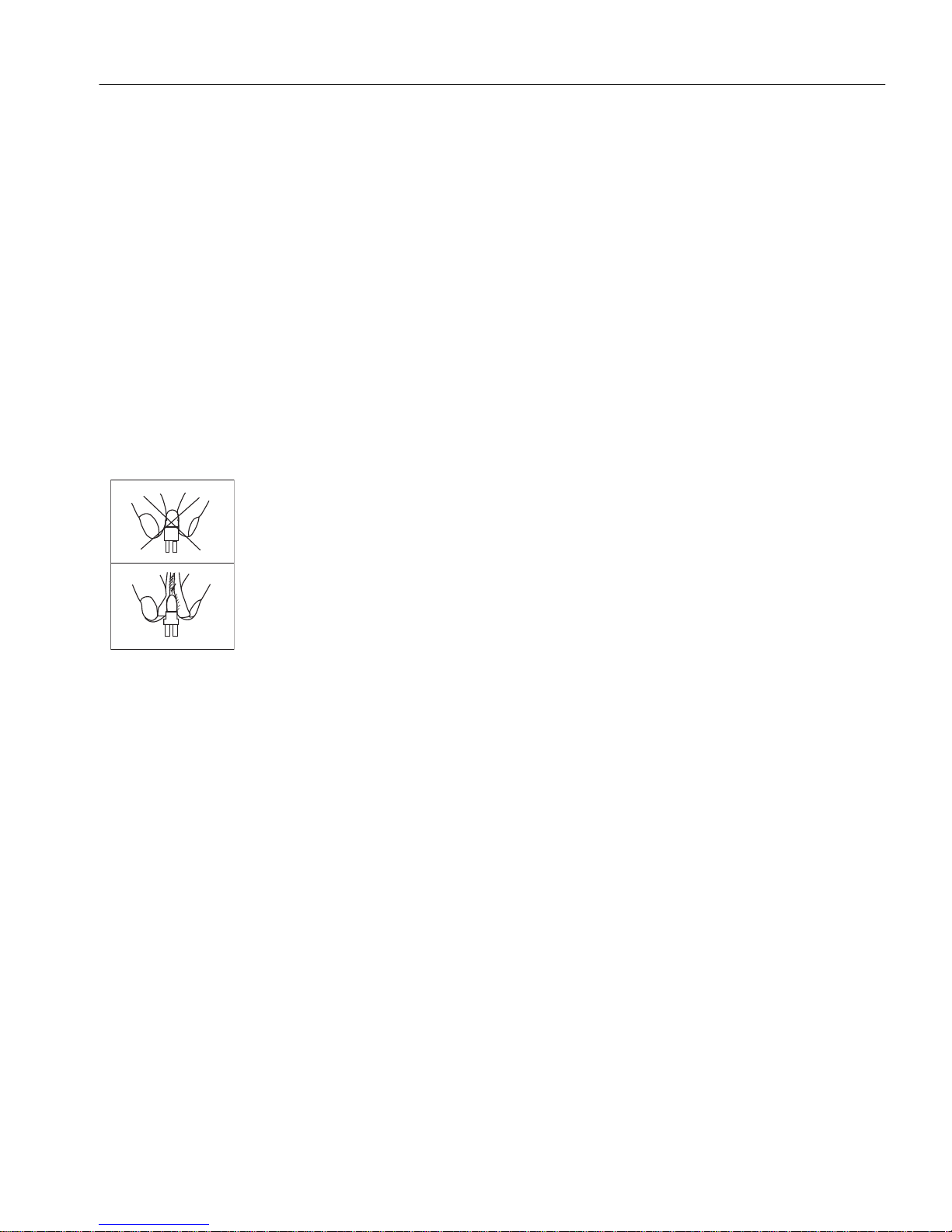
2.5 Notice: Be sure to follow the above figure when making your own cables. Do not
use the ground lug on the XLR connector. Do not connect the cable’s shield
conductor to the ground lug or allow the shield conductor to come in contact with the
XLR’s outer casing. Grounding the shield could cause a short circuit and erratic
behavior.
2.6 Special Note: Line Termination. When longer runs of cable are used, you may
need to use a terminator on the last fixture to avoid erratic behavior. A terminator is
a 90-120 ohm 1/4 watt resistor which is connected between pins 2 and 3 of a male
XLR connector (DATA + and DATA -). This fixture is inserted in the female XLR
connector of the last fixture in your daisy chain to terminate the line. Using a cable
terminator (ADJ part number Z-DMX/T) will decrease the possibilities of erratic
behavior.
©Elation Professionals® Los Angeles, Ca. - wwww.ElationLighting.com - Page 16
1
3
2
Power Spot 700™
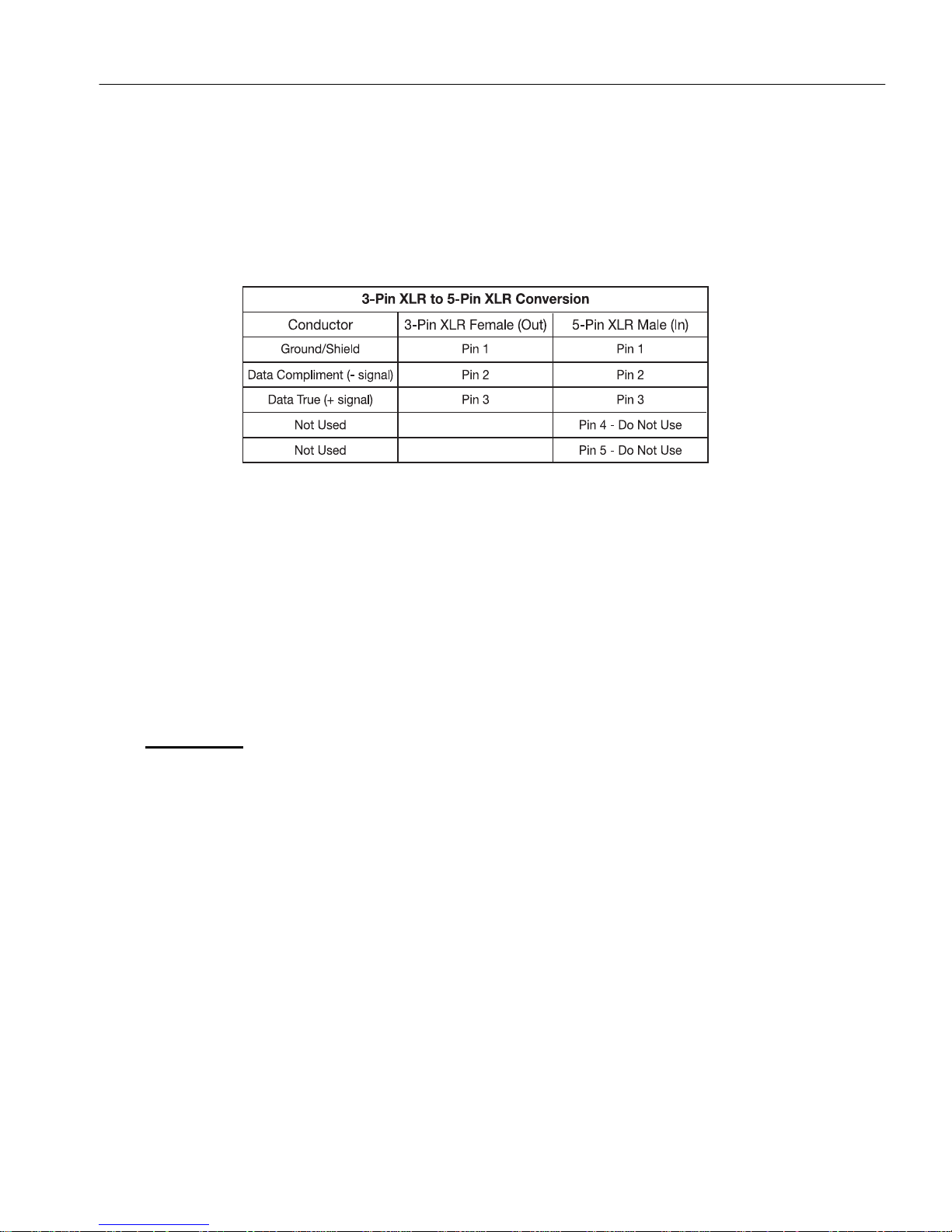
2.7 5-Pin XLR DMX Connectors. Some manufactures use 5-pin XLR connectors for
DATA transmission in place of 3-pin. 5-pin XLR fixtures may be implemented in a 3pin XLR DMX line. When inserting standard 5-pin XLR connectors in to a 3-pin line a
cable adaptor must be used, these adaptors are readily available at most electric
stores. The chart below details a proper cable conversion.
2.8 Fuse Requirements
The POWER SPOT 700’s electronic and lamp systems are protected by two GMA
(5x20mm) external fuses:
Lamp: 250v/10A (120v Operation) or 250v/5A (220v Operation)
Electronics: 250v/2A (120v Operation) or 250v/1A (220v Operation)
The fuse requirements are clearly printed on the side of the fixture.
WARNING:
• Always disconnect main power before changing the fuse!
• Always replace with the exact same type fuse unless otherwise specified
by an authorized Elation® service technician. Replacing with anything
other than the specified fuse can severely damage your fixture and will
void your manufactures warranty.
2.9 Transportation and Handling
The POWER SPOT 700™ comes with two carrying handles built into the base.
Always transport the fixture by these handles. Never lift or carry the POWER SPOT
700™ by the yoke (head assembly) this can seriously damage the unit and will void
your manufactures warranty.
©Elation Professionals® Los Angeles, Ca. - wwww.ElationLighting.com - Page 17
 Loading...