

Page 1

Instruction Manual
Version 1.2
4295 Charter Street
Elation Professional
Los Angels CA 90058
e-mail: info@elationlighting.com
Web site: www.elationlighting.com
Page 2
(V1.2) 2
Page 3

Contents
1 Introduction...........................................................................................................................5
1.1 Safety Rules...................................................................................................................7
2 Installation .............................................................................................................................8
2.1 Mounting.........................................................................................................................8
2.1.1 Clamps (Hooks)................................................................................................8
2.1.2 Mountingplate (optional).................................................................................8
2.2 Securing ........................................................................................................................8
2.3 Connectors....................................................................................................................9
2.3.1 AC Connectors.................................................................................................9
2.3.2 DMX...................................................................................................................9
2.4 Fuses..............................................................................................................................9
3 The Menu Field ................................................................................................................... 10
3.1 DMX- Channel Addresssing......................................................................................10
3.2 Read outs of Lamp and Unit Running Time .............................................................11
3.2.1 Lamp Time 1................................................................................................... 11
3.2.2 Lamp Time 2................................................................................................... 11
3.2.3 Life Time..........................................................................................................11
3.3 The CODE Level.........................................................................................................11
3.4 The Test Level.............................................................................................................12
3.4.1 Selftest Procedure..........................................................................................12
3.5 Temperature Control 1 ............................................................................................... 12
4 Channel selection ( Overview table ) ............................................................................13
5 Lamp Installation............................................................................................................... 16
5.1 Safety Rules.................................................................................................................16
5.2 How to Install New Lamp............................................................................................17
(V1.2) 3
Page 4

6 Gobo Replacement ........................................................................................................... 18
6.1 Safety Rules.................................................................................................................18
6.2 How to Replace the Gobos........................................................................................18
7 Maintenance........................................................................................................................20
7.1 Mirror and Optical System.........................................................................................20
7.1.1 Cleaning the inside Mirror and the outside Optical System ....................20
7.1.2 Cleaning the outside Optical System..........................................................21
7.2 Ventilation System......................................................................................................22
8 Technical Data /Overview................................................................................................23
(V1.2) 4
Page 5
1 Introduction
Illustration 1-1
(V1.2) 5
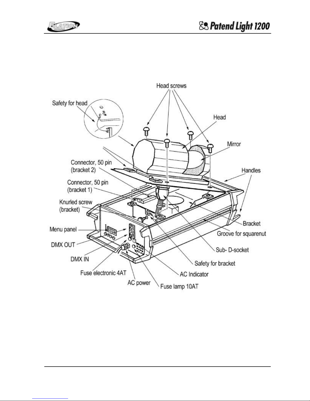
Page 6
Illustration 1-2
(V1.2) 6
Page 7

1.1 Safety Rules
The PPAATTEENNDD--LLIIGGHHTT 11220000 is a High-Tech Product. To guarantee smooth operation,
it is necessary to follow all safety rules.
1. Make sure that Head and Mirror of the PPAATTEENNDD--LLIIGGHHTT 11220000, can rotate without
any mechanical problems and that all fan openings are clean and not blocked by
anything.
2. Touchin g the head while moving can cause serious injuries
3. Unplug the PPAATTEENN DD--LLIIGGHH TT 11220000 from the AC outlet before any service
4. It is necessary to wait at least 30 minutes after disconnecting the AC before you
open the PPAATTEENNDD--LLIIGGHHTT 11220000. Please do not touch the Bulb if you are not
absolutely sure it is cold. -Danger of BURNING-
5. The PATEND-LIGHT 1200 is provided with a protective switch to switch off the
lamp when opening it. Never Bridge this protective switch. This can cause
serious damage to your retina.
6. To allow a secure operation, follow the Installation guide described in chapter 2.
Operating the PPAATTEENNDD--LLIIGGHHTT 11220000 without suited safety aids like safety cables
or clamps/hooks can increase the risk of an accident.
7. The installation should be done by a qualified technician only.
(V1.2) 7
Page 8

2 Installation
2.1 Mounting
To mount the PPAATTEENNDD--LLIIGGHHTT 11220000 use the 8 threads M12 at the backside of the
system or use the slide nuts at the side of the body.
2.1.1 Clamps (Hooks)
Mount clamps and/or hooks directly to the base plate.
Please make sure to use right sized clamps and hooks and fit them securely.
2.1.2 Mounting plate (optional) part #: MP -PATENT
For easy mounting you can purchase an optional mounting plate. The mounting
plate consists of 2 light weight plates. 1 plate mounts on the truss, the second
plate mounts on the fixture, the 2nd plate allows the PPAATTEENNDD--LLIIGGHHTT 11220000 to
easily slide onto the 1st plate.
The PPAATTEENNDD--LLIIGGHHTT 11220000 is fully operational whether it stands, hangs or is
mounted to the wall.
The PPAATTEENNDD--LLIIGGHHTT 11220000,, when standing on the groun d, requires an even
surface. Make sure that the fan openings are not blocked by any
circumstances.
2.2 Secure the Patend Light 1200
Always use safety cables to secure the PPAATTEENNDD--LLIIGGHHTT 11220000, use the eye bolt and
slide nut provided on the side of the fixture.
(V1.2) 8
Page 9

2.3 Connectors
2.3.1 AC Connectors
230 Volt, 50 Hz
2.3.2 DMX
DMX 512 Standard input/output
Please see printing on the case for the right Pin usage!
[+] = Pin 3 / [-] = Pin 2 / [Ground] = Pin 3
The DMX- Address starts at the PPAATTEENNDD--LLIIGGHHTT 11220000 at the DMX - Address
[001] (from software version P 3.0).
This can be changed to the DMX - Start address [000]. For this hold the
Data+
and
key while switching on the PPAATTEENNDD--LLIIGGHHTT 11220000..
2.4 Fuses
The PPAATTEENNDD--LLIIGGHHTT 11220000 electronic system is protected by a 5x20 T4A fuse 250V.
The lamp is protected by a 5x20 T10A fuse 250V. Please see the printing on the
PPAATTEENNDD--LLIIGGHHTT 11220000,,
for more details see Illustration 1-1 in Chapter 1
Disconnect AC outlet before changing a fuse !!!
Menu
(V1.2) 9
Page 10

3 The Menu Field
3.1 DMX- Channel Addressing
Right after turning on the PPAATTEENNDD--LLIIGGHHTT 11220000 you can see the current DMXAddress. Choose this as follows.
Select the DMX-Level and press the menu key.
This level is called on automatically after turning on the PPAATTEENNDD--LLIIGGHHTT 11220000.
Select the figure you want to adjust by pressing the Cursor key.
The selected figure begins to flash.
Adjust the figure by pressing the Data+ or Data- key.
Confirm the DMX-Address by pressing the Menu key once.
If there is no DMX- Signal, a (-) will flash in the display.
The DMX-Address will be stored when switching off the PPAATTEENNDD--LLIIGGHHTT 11220000 !!!
(V1.2) 10
Page 11

3.2 Read outs of Lamp and Unit Running Time.
Select the time level by pressing the Menu key twice.
Select the requested time by pressing the Cursor key,
3.2.1 Lamp Time 1
The current lamp time is shown alternating with LA 1. This is the total hours
used in the current lamp.
This time can be cleared by pressing the Data + and Data – keys at the same
time. Usually done when adding a new lamp.
3.2.2 Lamp Time 2
The total lamp time is shown alternating with LA 2. this time can’t be cleared.
This is the total hours of all lamp lives.
3.2.3 Life Time
The life time is shown alternating with LIFE. This is the total hours of usage for
the entire fixture.
3.3 The CODE Level
This level is accessed by authorized dealers only.
In this level you can adjust all functions. Also the change of Pan/Tilt high-byte and low-
byte is possible.
(V1.2) 11
Page 12

3.4 The Test Level
The Test Level makes a function test or a self test procedure possible.
3.4.1 Self test Procedure
Select the requested test level by pressing the Cursor key.
Start the Self test program by pressing the Data+ key. The lamp can be
started by pressing the Data+ and Data- keys for 5 seconds at the same time.
You have the following sections:
PR Self test of all functions
PAN T est Head movement
TILT Test Mirror movement
PSA Test Prism
DI Test Dimmer
Shut Test Shutter
CLr Test Color wheel
GB1 Test Gobo wheel 1
GB2 Test Gobo wheel 2
IrIS Test Iris
Gr1 Test Gobo rotation 1
FOCS Test Focus
Gr2 Test Gobo rotation 2
Forward with the Data+ key. – Backward with the Data- key.
3.5 Temperature Control 1
If the temperature value deviates too much from the system standard, the lamp will
turn off automatically.
Reconnection can only be made by authorized dealers.
(V1.2) 12
Page 13

4 Channel selection ( Overview table )
Channel Description DMX-Value Hex-Value Value %
1) Head Head position, High Byte (0o-360o ) 0 - 255 0 - FF 0 – 100%
2) Head Head position, Low Byte (0o-1,41o) 0 - 255 0 - FF 0 – 100%
3) Mirror Mirror position, High Byte (0o-360o) 0 - 255 0 - FF 0 – 100%
4) Mirror Mirror position, Low Byte(0o-1,41o) 0 - 255 0 - FF 0 – 100%
5) Speed
Head
6) Speed
Mirror
7) Special
Function
Relative Movement 0 0 0%
Pos < 360o Pos < 360o 1 - 19 1 - 13 1 – 7%
Pos > 360o Pos > 360o 20 - 29 14 - 1D 8 – 11%
Pos < 360o Pos > 360o 30 - 39 1E -27 12 – 15%
Pos > 360o Pos < 360o 40 - 49 28 - 31 16 – 19%
Rotation left Pos < 360o 50 - 59 31 - 3B 20 – 23%
Rotation left Pos > 360o 60 - 69 3C - 45 24 – 27%
Rotation right Pos < 360o 70 - 79 46 - 4F 28 – 30%
Rotation right Pos > 360o 80 - 89 50 - 59 31 – 35%
Pos < 360o Rotation left 90 - 99 5A - 63 36 – 38%
Pos > 360o Rotation left 100 - 109 64 - 6D 39 – 42%
Pos < 360o Rotation right 110 - 119 6E - 77 43 – 46%
Pos > 360o Rotation right 120 - 129 78 - 81 47 – 50%
Rotation left Rotation left 130 - 139 82 - 8B 51 – 54%
Rotation right Rotation right 140 - 149 8C - 95 55 – 58%
Rotation left Rotation right 150 - 159 96 - 9F 59 – 62%
Rotation right Rotation left 160 - 254 A0 - FE 63 – 98%
Reset without Shutter 254 FE 99%
Reset for all Functions 255 FF 100%
8) Color color 1 (white) 0 - 4 0 - 4 1%
bi (white – green) 5 - 9 5 - 9 2 – 3%
color 2 (green) 10 - 14 A - E 4 – 5%
bi (green – red) 15 - 19 F - 13 6 – 7%
color 3 (red) 20 -24 14 - 18 8 – 9%
bi (red – dark blue) 25 - 29 19 - 1D 10 – 11%
color 4 (dark blue) 30 - 34 1E - 22 12 – 13%
bi (dark blue – yellow) 35 - 39 23 - 27 14 – 15%
color 5 (yellow) 40 - 44 28 - 2C 16 – 17%
bi (yellow – pink) 45 - 49 2D - 31 18%
Speed Head, 1/8min - 7/sec 0 - 255 0 - FF 0 – 100%
Speed Mirror, 1/4min - 3/sec 0 - 255 0 - FF 0 – 100%
Head Mirror
(V1.2) 13
Page 14

Channel Description DMX-Value Hex-Value Value %
8) Color color 6 (pink) 50 - 54 32 - 36 19 – 20%
bi (pink – turquoise) 55 -59 37 - 3B 21 – 22%
color 7 (turquoise) 60 - 64 3E - 40 23 – 24%
bi (turquoise – orange) 65 - 69 41 - 45 25 – 26%
color 8 (orange) 70 - 74 46 - 4A 27 – 28%
bi (orange – cyan) 75 - 79 4B - 4F 29 – 30%
color 9 (cyan) 80 - 84 50 - 54 31 – 32%
bi (cyan – magenta) 85 - 89 55 - 59 33 – 34%
color 10 (magenta) 90 - 94 5A - 5E 35 – 36%
bi (magenta – white) 95 - 99 5F - 63 37 – 39%
rotation cw slow – fast 128 - 191 80 - BF 50 – 74%
Stop 192 C0 75%
rotation ccw slow – fast 193 - 255 C1 - FF 76-100%
9) Gobow. 1 Gobo 1 (open) 0 - 9 0 - 9 0 – 3%
Gobo 2 (rotation + posi) 10 - 19 A - 13 4 – 7%
Gobo 3 (rotation + posi) 20 - 29 14 - 1D 8 – 11%
Gobo 4 (fixed) 30 - 39 1E - 27 12 – 15%
Gobo 5 (rotation + posi) 40 - 49 28 - 31 16 – 19%
Gobo 6 (rotation + posi) 50 - 127 32 - 7F 20 – 50%
rotation cw fast – slow 128 - 191 80 - BF 51 – 74%
Stop 192 C0 75%
rotation ccw slow – fast 193 - 255 C1 – FF 76-100%
10) Shutter shutter open 0 - 9 0 – 9 0 – 3%
shutter close 1 10 – 19 A – 13 4 – 7%
shutter close 2 20 - 29 14 – 1D 8 – 11%
shutter slow – fast 30 – 99 1E – 63 12 – 38%
shutter close 1 100 – 250 64 – FA 39 – 98%
shutter open 251 - 255 FB - FF 99-100%
11) Gobo 1 Stop 0 – 4 0 – 4 0 – 1%
Rotation 1 rotation cw slow – fast 5 – 24 5 – 18 2 – 9%
Stop 25 – 29 19 – 1D 10 – 11%
rotation ccw slow – fast 30 – 49 1E – 31 12 – 19%
Stop 50 – 54 32 – 36 20 – 21%
gobo position 55 - 255 37 – FF 22-100%
12) Iris Iris 100% - 4% open 0 - 255 0 – FF 0 – 100%
13) Focus min -. Max 0 - 255 0 – A 0 – 100%
14) Gobow. 2 Gobo 1 (open) 0 – 9 0 - 9 0 – 3%
Gobo 2 (rotation) 10 – 19 A - 13 4 – 7%
Gobo 3 (rotation) 20 – 29 14 - 1D 8 – 11%
Gobo 4 (color correction filter) 30 – 39 1E - 27 12 – 15%
Gobo 5 (rotation) 40 – 44 28 – 7B 16 – 17%
Gobo 6 (rotation) 45 – 123 2D – 7B 18 – 49%
(V1.2) 14
Page 15

Channel Description DMX-Value Hex-Value Value %
rotation cw slow . fast 124 – 191 80 - BF 50 – 74%
Stop 192 C0 75%
rotation ccw slow – fast 193 – 255 C1 - FF 76 – 100%
15) Gobo 2 Stop 0 – 15 0 - F 0 – 5%
Rotation rotation cw slow – fast 16 – 143 10 - 8F 6 – 55%
Stop 144 90 56%
rotation ccw slow – fast 145 –255 91 - FF 57 – 100%
16) Prism open 0 – 9 0 – 9 0 – 3%
prism 1 10 – 19 A – 13 4 – 7%
rot. cw prism 1 slow – fast 20 – 69 14 – 45 8 – 26%
Stop 70 46 27%
rot. ccw prism 1 slow – fast 71 – 119 47 – 77 28 – 46%
Stop 120 78 47%
Effect (frost fi lter) 121 - 129 79 – 81 48 – 50%
prism 2 130 – 139 82 – 8B 51 – 54%
rot. cw prism 2 slow – fast 140 – 189 8C – BD 55 – 73%
Stop 190 BE 74%
rot. ccw prism 2 slow – fast 191 – 239 BF – EF 75 – 93%
Stop 240 – 255 F0 – FF 94 – 100%
17) Dimmer close (0%) 0 – 9 0 – 9 0 – 3%
close – open (0 – 100%) 10 – 249 A – F9 4 – 97%
open (100%) 250 – 255 FA – FF 98 – 100%
Lamp on Shutter (min 2 sec)
dimmer
Lamp on
(from softwareversion 2.2, this is
also shown in the
display)
Shutter (min 2 sec)
dimmer
Lamp off shutter (min 2sec)
dimmer
iris (max 5sec)
Lamp off
(from software-version 2.2,
this is also shown in the
display)
shutter (min 2sec)
dimmer
iris (max 5sec)
240 – 245
250 – 255
240 – 255
250 – 255
246 – 250
0 – 9
x– 255- 0
230 – 250
0 – 9
x– 255- 0
F0 – F5
FA – FF
F0 – FF
FA – FF
F6 – FA
0 – 9
x - FF - 0
E6 – FA
0 – 9
x - FF - 0
94 – 96%
98 – 100%
94 – 100%
98 – 100%
97 – 98%
0 – 3%
x– 100 –0%
90 – 98%
0 – 3%
x– 100 –0%
Relative Movement:
If DMX- Channel Nr.7 (Special) is on DMX- [000] you can contr ol the PPAATTEENNDD--LLIIGGHHTT
0 in Relative Movement. Therefore the Speed channels No. 5/6 must also be on
1122000
DMX- [000] If you have a DMX- Value on one of these channels it is automatically on
Absolute Movement. While programming circles or other movements please use the
Absolute Movement.
(V1.2) 15
Page 16

5 Lamp Installation
For a hassle free Lamp Installation, it is absolutely necessary to follow all descriptions in
this chapter step by step.
5.1 Safety Rules
• Unplug AC power connection
• Allow to cool (min. 30 minutes)
• Don’t touch lamp w ith bare fingers.
• Install the lamp with the filler to the right direction. (see Illustration 5-1)
• Distance between lamp and lens holder must bee min. 5mm.
• Close the PPAATTEENN DD--LLIIGGHHTT 11220000 before you connect the AC power!
Illustration 5-1
(V1.2) 16
Page 17

5.2 How to Install lamp
Please see Illustration 1-1 and 5-1/2.
1. Unscrew screws on the head with 8mm wrench.
2. Press the two safety levers at the same time and lift carefully the head plate.
3. Remove Sub-D socket by pressing the safety clips. Hang out the safety loop and
lift the head plate cautiously.
4. Remove the multiple pin strip 1 and 2.
5. Open the knurled screw of the Optical Slide.
6. Hang out the safety of the Optical Slide in.
7. Take out the Optical Slide in carefully.
8. Unscrew the M4 screw of the optical plate.
9. Open the upper part of the optical device.
10.Unscrew the HMI lamp nuts and change the lamp.
The lamp filler must be placed according to the illustration !!!
11.Close the PPAATTEENNDD--LLIIGGHHTT 11220000 in reverse order.
Attention: Make sure that the optical slide in fits in both grooves !!!
Ill ustration 5-2
(V1.2) 17
Page 18

6 Gobo Replacement
The PATEND-LIGHT 1200 is fitted with standard Gobos (37,5 mm, picture size 27,0 mm).
To change one of these it is necessary to open the PPAATTEENNDD--LLIIGGHHTT 11220000 and to remove
the optical system.
6.1 Safety Rules
• Unplug AC power connect ion
• Allow to cool (over 30 minutes)
• Don’t touch lamp with bare fingers.
• Close the PPAATTEENNDD--LLIIGGHHTT 11220000 before you connect the AC power!
6.2 How to replace the Gobos
Please see Illustration 1-1 and 6-1.
1. Unscrew screws on the head with 8mm wrench.
2. Press the two safety levers at the same time and lift carefully the head plate.
3. Remove Sub-D socket by pressing the safety clips. Hang out the safety loop and
lift the head plate cautiously.
4. Remove the multiple pin strip 1 and 2.
5. Open the knurled screw of the Optical Screw.
6. Hang out the safety of the Optical Slide in.
7. Take out the Optical Slide in carefully.
8. Unscrew the 4 screws of the Optical Slide in.
9. Put down the upper part of the Optical Slide in head first.
10. Remove the little claps which holds the Gobos with a little screwdriver.
11. Change the Gobos and mount the claps aback to its position. Please make sure,
that the Gobo fits correct.
12. Close the PPAATTEENNDD--LLIIGGHHTT 11220000 in reverse order.
(V1.2) 18
Page 19

Illustration 6-1
Attention: Make sure that the optical slide in fits in both grooves !!!
If you use Glass -Gobos make sure that the mirror side faces the lamp side.
(V1.2) 19
Page 20

7 Maintenance
The cleaning of the inner optical System, color filters, color correction filter and lenses
should be done by qualified technician only! Contact your local ELATION Dealer for
details.
DO NOT use strong detergents, acid etc. for cleaning the case.
7.1 Mirror and Optical System
Clean the PPAATTEENNDD--LLIIGGHHTT 11220000 optical system with a moistened cloth and a little
cleaner.
7.1.1 Cleaning the inside Mirror and the outside Optical System
Illustration 7-1
Open the screws
Remove the Mirror Blind
(V1.2) 20
Page 21

7.1.2 Cleaning the outside Optical System
Illustration 7-2
1. Unscrew screws on the head with 8mm wrench.
2. Press the two safety levers at the same time and lift carefully the head plate.
3. Remove Sub-D socket by pressing the safety clips. Hang out the safety loop and
lift the head plate cautiously.
4. Unscrew the two screws of the aperture.
5. Clean the lenses inside
6. Close the PPAATTEENNDD--LLIIGGHHTT 11220000 iinn rreevveerrssee oorrddeerr..
(V1.2) 21
Page 22

7.2 Ventilation System
Illustration 7-3
It is necessary to clean the fan openings, air channels and fan gratings on a regular
base (depending on environment).
(V1.2) 22
Page 23

8 Technical Data /Overview
• Supply Data 230V/10AT
• 1200 HMI W/S Lamp, bilateral based, with 750h Lamp Life
• Capacitor compensation
• DMX 512 Standard
• Angle of spread 16°
• weight 32 kg
• Dimensions: 566 x 434 x 395 mm
• ROTO-Head
Min. 1 round per 8 minutes
Max. 7 rounds per second
0,02 degrees resolution
14.00/25.000 Microsteps/360
o
(V1.2) 23
Page 24

(V1.2) 24
 Loading...