

Page 1
PANEL XL IP
User Manual
Page 2

©2023 ELATION PROFESSIONAL all rights reserved. Information, specications, diagrams, images, and
instructions herein are subject to change without notice. ELATION PROFESSIONAL logo and identifying
product names and numbers herein are trademarks of ELATION PROFESSIONAL. Copyright protection
claimed includes all forms and matters of copyrightable materials and information now allowed by
statutory or judicial law or hereinafter granted. Product names used in this document may be trademarks
or registered trademarks of their respective companies and are hereby acknowledged. All non-ELATION
brands and product names are trademarks or registered trademarks of their respective companies.
ELATION PROFESSIONAL and all aliated companies hereby disclaim any and all liabilities for property,
equipment, building, and electrical damages, injuries to any persons, and direct or indirect economic
loss associated with the use or reliance of any information contained within this document, and/or as a
result of the improper, unsafe, insucient and negligent assembly, installation, rigging, and operation
of this product.
Elation Professional USA | 6122 S. Eastern Ave. | Los Angeles, CA. 90040
323-582-3322 | 323-832-9142 fax | www.elationlighting.com | info@elationlighting.com
Elation Professional B.V. | Junostraat 2 | 6468 EW Kerkrade, The Netherlands
+31 45 546 85 66 | +31 45 546 85 96 fax | www.elationlighting.eu | info@elationlighting.eu
Elation Professional Mexico | AV Santa Ana 30 | Parque Industrial Lerma, Lerma, Mexico 52000
+52 (728) 282-7070
DOCUMENT VERSION
Due to additional product features and/or enhancements, an updated version of this
document may be available online. Please scan the QR Code with your mobile device or
visit www.elationlighting.com for the latest revision/update of this manual, before
installation and/or programming.
Date
Document
Version
Software
Version
DMX Channel Mode Notes
08/23/22 1.0 1.07 1/4/7/6/12/24/48/96/14/23/58/04/12 Initial Release
12/13/22 1.1 N/C No Change
08/01/23 1.2 N/C No Change
Updated Dimensional Drawings,
Specications
Updated IP65 statement and
thermal specication
2
Page 3

CONTENTS
General Information 4
Limited Warranty 5
Safety Guidelines 6
Maintenance Guidelines 8
IP65 Rated 9
Fixture Overview 10
Fan Modes and Low Noise Operation
Torque Screw Settings
Installation Instructions 13
Clamp Installation 14
Junior Pin Installation 15
Stand Mount Installation 16
Barn Door Installation 17
Intensifier Installation 18
Power Cables 19
Battery Connection 21
System Menu 22
Manual Mode 26
DMX Traits: 27
Channel Functions & Values 27
FX Table 31
FX Adjust Table 33
Color Temperature 34
11
12
Virtual Swatch Book 35
Remote Device Management (RDM)
Error Codes
Refresh Rate 37
Dimmer Modes / Dimmer Curves 38
Pixel Zones 39
Specifications 40
Dimensional Drawings 41
Optional Accessories | FCC Statement 42
3
36
37
Page 4

GENERAL INFORMATION
INTRODUCTION
Please read and understand the instructions in this manual carefully and thoroughly before
attempting to operate this device. These instructions contain important safety and use
information. For professional use only
UNPACKING
Every device has been thoroughly tested and has been shipped in perfect operating condition.
Carefully check the shipping carton for damage that may have occurred during shipping. If the
carton is damaged, carefully inspect the device for damage, and be sure all accessories necessary
to install and operate the device have arrived intact. In the event that damage has been found
or parts are missing, please contact our customer support team for further instructions. Please
do not return this device to your dealer without rst contacting customer support. Please do
not discard the shipping carton in the trash. Please recycle whenever possible.
BOX CONTENTS
Fixture (x1)
Junior Pin (1x)
Barndoor Assembly (x1)
Power Cable (x1)
Barndoor Safety Cable (x1)
CUSTOMER SUPPORT
Contact ELATION Service for any product related service and support needs.
Also visit forums.elationlighting.com with questions, comments, or suggestions.
ELATION SERVICE USA - Monday - Friday 8:00am to 4:30pm PST
323-582-3322 | Fax 323-832-9142 | support@elationlighting.com
ELATION SERVICE EUROPE - Monday - Friday 08:30 to 17:00 CET
+31 45 546 85 63 | Fax +31 45 546 85 96 | support@elationlighting.eu
REPLACEMENT PARTS please visit parts.elationlighting.com
4
Page 5

LIMITED WARRANTY (USA ONLY)
A. Elation Professional hereby warrants, to the original purchaser, Elation Professional products to be
free of manufacturing defects in material and workmanship for a period of two years (730 days),
and Elation Professional product rechargeable batteries to be free of manufacturing defects in
material and workmanship for a period of six months (180 days), from the original date of purchase.
This warranty excludes discharge lamps and all product accessories. This warranty shall be valid
only if the product is purchased within the United States of America, including possessions and
territories. It is the owner’s responsibility to establish the date and place of purchase by acceptable
evidence, at the time service is sought.
B. For warranty service, send the product only to the Elation Professional factory. All shipping charges
must be pre-paid. If the requested repairs or service (including parts replacement) are within the
terms of this warranty, Elation Professional will pay return shipping charges only to a designated
point within the United States. If any product is sent, it must be shipped in its original package
and packaging material. No accessories should be shipped with the product. If any accessories are
shipped with the product, Elation Professional shall have no liability what so ever for loss and/or
damage to any such accessories, nor for the safe return thereof.
C. This warranty is void if the product serial number and/or labels are altered or removed; if the
product is modied in any manner which Elation Professional concludes, after inspection, aects
the reliability of the product; if the product has been repaired or serviced by anyone other than the
Elation Professional factory unless prior written authorization was issued to purchaser by Elation
Professional; if the product is damaged because not properly maintained as set forth in the product
instructions, guidelines and/or user manual.
D. This is not a service contract, and this warranty does not include any maintenance, cleaning or
periodic check-up. During the periods as specied above, Elation Professional will replace defective
parts at its expense, and will absorb all expenses for warranty service and repair labor by reason
of defects in material or workmanship. The sole responsibility of Elation Professional under this
warranty shall be limited to the repair of the product, or replacement thereof, including parts, at
the sole discretion of Elation Professional. All products covered by this warranty were manufactured
after January 1, 1990, and bare identifying marks to that eect.
E. Elation Professional reserves the right to make changes in design and/or performance improvements
upon its products without any obligation to include these changes in any products theretofore
manufactured.
F. No warranty, whether expressed or implied, is given or made with respect to any accessory supplied
with the products described above. Except to the extent prohibited by applicable law, all implied
warranties made by Elation Professional in connection with this product, including warranties of
merchantability or tness, are limited in duration to the warranty periods set forth above. And no
warranties, whether expressed or implied, including warranties of merchantability or tness, shall
apply to this product after said periods have expired. The consumer’s and/or dealer’s sole remedy
shall be such repair or replacement as is expressly provided above; and under no circumstances shall
Elation Professional be liable for any loss and/or damage, direct and/or consequential, arising out of
the use of, and/or the inability to use, this product.
G. This warranty is the only written warranty applicable to Elation Professional products and supersedes
all prior warranties and written descriptions of warranty terms and conditions heretofore published.
WARRANTY RETURNS
All returned service items whether under warranty or not, must be freight pre-paid and accompany
a return authorization (R.A.) number. The R.A. number must be clearly written on the outside of the
return package. A brief description of the problem as well as the R.A. number must also be written
down on a piece of paper and included in the shipping container. If the unit is under warranty, you must
provide a copy of your proof of purchase invoice. Items returned without a R.A. number clearly marked
on the outside of the package will be refused and returned at customer’s expense. You may obtain a R.A.
number by contacting customer support.
5
Page 6
SAFETY GUIDELINES
This fixture is a sophisticated piece of electronic equipment. To guarantee smooth operation, it
is important to follow all instructions and guidelines in this manual. Elation Professional is not
responsible for injury and/or damages resulting from the misuse of this fixture due to the disregard
of the information printed in this manual. Only qualified and/or certified personnel should perform
installation of this fixture and only the original rigging parts included with this fixture should be used
for installation. Any modifications to the fixture and/or the included mounting hardware will void the
original manufacturer’s warranty and increase the risk of damage and/or personal injury.
PROTECTION CLASS 1 - FIXTURE MUST BE PROPERLY GROUNDED.
THERE ARE NO USER SERVICEABLE PARTS INSIDE THIS UNIT. DO NOT ATTEMPT
ANY REPAIRS YOURSELF. DOING SO WILL VOID YOUR MANUFACTURER’S
WARRANTY. DAMAGES RESULTING FROM MODIFICATIONS TO THIS DEVICE
AND/OR THE DISREGARD OF SAFETY INSTRUCTIONS AND GUIDELINES IN THIS
MANUAL VOID THE MANUFACTURER’S WARRANTY AND ARE NOT SUBJECT TO
ANY WARRANTY CLAIMS AND/OR REPAIRS.
ENSURE ALL CONNECTIONS AND END CAPS ARE PROPERLY SEALED WITH A
DIELECTRIC GREASE (AVAILABLE AT MOST ELECTRICAL SUPPLIERS) TO PREVENT
WATER CORROSION AND/OR ELECTRICAL SHORT CIRCUIT.
DO NOT PLUG THIS UNIT INTO A DIMMER PACK!
NEVER OPERATE THIS UNIT WITH THE CASING REMOVED!
DISCONNECT POWER BEFORE PERFORMING MAINTENANCE!
NEVER TOUCH DURING OPERATION, AS FIXTURE SURFACES MAY BE HOT!
NEVER LOOK DIRECTLY INTO THE LIGHT SOURCE!
RETINA INJURY RISK - MAY INDUCE BLINDNESS!
SENSITIVE PERSONS MAY SUFFER AN EPILEPTIC SHOCK!
6
Page 7

SAFETY GUIDELINES
• DO NOT TOUCH the xture housing during operation.
• Turn OFF the power and allow approximately 15 minutes for the xture to cool down before serving.
• DO NOT shake xture and avoid brute force when installing and/or operating xture.
• DO NOT operate xture if the power cord is frayed, crimped, damaged, and/or if any of the power
cord connectors are damaged and do not insert into the xture securely with ease.
• NEVER force a power cord connector into the xture. If the power cord or any of its connectors are
damaged, replace it immediately with a new one of the same rating.
• DO NOT block any air ventilation slots.
• All fan and air inlets must remain clean and never blocked.
• Allow approx. 6” (15cm) between xture and other devices or a wall for proper cooling.
• When installing xture in a suspended environment, always use mounting hardware that is no less
than M10 x 25 mm, and always install xture with an appropriately rated safety cable.
• Always disconnect xture from main power source before performing any type of service and/or
cleaning procedure.
• Only handle the power cord by the plug end, and never pull out the plug by tugging the wire portion
of the cord.
• During the initial operation of this xture, a light smoke or smell may emit from the interior of the
xture. This is a normal process and is caused by excess paint in the interior of the casing burning o
from the heat associated with the lamp and will decrease gradually over time.
• Consistent operational breaks will ensure xture will function properly for many years.
• ONLY use the original packaging and materials to transport the xture for service.
7
Page 8

MAINTENANCE GUIDELINES
DISCONNECT POWER BEFORE PERFORMING ANY MAINTENANCE!
CLEANING
Frequent cleaning is recommended to ensure proper function, optimized light output, and an
extended life. The frequency of cleaning depends on the environment in which the fixture
operates: damp, smoky, or particularly dirty environments can cause greater accumulation
of dirt on the fixture’s optics. Clean periodically with a soft cloth to avoid dirt/debris
accumulation.
NEVER use alcohol, solvents, or ammonia-based cleaners.
MAINTENANCE
Regular inspections are recommended to ensure proper function and extended life. There are
no user serviceable parts inside this fixture. Please refer all service issues to an authorized
Elation service technician. Should you need any spare parts, please order genuine parts from
an authorized Elation dealer.
Please refer to the following points during routine inspections:
• A detailed electrical check by an approved electrical engineer every three months, to
make sure the circuit contacts are in good condition and prevent overheating.
• Be sure all screws and fasteners are securely tightened at all times. Loose screws may fall
out during normal operation, resulting in damage or injury as larger parts could fall.
• Check for any deformations on the housing, color lenses, rigging hardware, and rigging
points (ceiling, suspension, trussing). Deformations in the housing could allow for dust
to enter into the fixture. Damaged rigging points or unsecured rigging could cause the
fixture to fall and seriously injure a person(s).
• Electric power supply cables must not show any damage, material fatigue, or sediments.
NEVER remove the ground prong from the power cable.
8
Page 9

IP65 RATED
The International Protection (IP) rating system is commonly expressed as “IP” (Ingress Protection)
followed by two numbers (i.e. IP65), where the numbers dene the degree of protection. The rst digit
(Foreign Bodies Protection) indicates the extent of protection against particles entering the xture,
and the second digit (Water Protection) indicates the extent of protection against water entering the
xture. An IP65 rated lighting xture is designed and tested to protect against the ingress of dust (6),
and low-pressure water jets from any direction (5).
NOTE: THIS FIXTURE IS INTENDED FOR TEMPORARY OUTDOOR USE ONLY!
Maritime/Coastal Environment Installations: A coastal environment is seaside adjacent, and caustic
to electronics through exposure to atomized salt-water and humidity, whereas maritime is anywhere
within 5-miles of a coastal environment.
NOT suitable for maritime/coastal environment installations. Installing this xture
in a maritime/coastal environment may cause corrosion and/or excessive wear to the
interior and/or exterior components of the xture. Damages and/or performance
issues resulting from installation in a maritime/coastal environment will void the
manufactures warranty, and will NOT be subject to any warranty claims and/or repairs.
Maritime installations require additional preparation, and additional service intervals may be needed
given the maritime use. In general, IP ratings presuppose freshwater conditions VS maritime conditions,
which are typically more “caustic” to IP xtures (both internally and externally). A duty-cycle may
also be needed when units are not in use. During times of high humidity and colder temperatures,
condensation may occur internally so the xture may require a duty-cycle to bring it up to running
temperature, allowing any accumulation of moisture to be expelled via the vent valve. Recommendations
can change based on installation environmental circumstances. A waterproof dome or similar device is
recommended for use in permanent outdoor installations. When using a dome, refer to manufacturer
recommendations for duty-cycle.
NOTE: NOT ALL FEATURES LISTED ARE AVAILABLE ON ALL FIXTURES; THE FOLLOWING INSTRUCTIONS
MAY NOT APPLY. CONTACT SUPPORT FOR ADDITIONAL DETAILS.
Exterior Maintenance: Inspect the exterior every 30-days. The unit must be powered o/disconnected.
The chassis should be inspected for any signs of contaminants. Inspect optics to determine if the lens
is obstructed, then clean optics and chassis accordingly. Based on initial nding, schedule maintenance
accordingly, keeping in mind that exterior maintenance will be required. Even if the luminaires are NOT
in use, maintenance will still be needed given its location (exterior use). The use of a durable type of
wax on the chassis is recommended since it will help prevent contaminant build up. Inspect both power
and data lines for any signs of contaminants or corrosion. Periodically reapplying di-electric grease,
especially in coastal environments. If any signs of corrosion/contaminants are present, clean thoroughly,
and/or replace connectors, then reapply di-electric grease. Typically, this should be done annually, or
any time an opportunity presents itself. As a preventive measure, annual replacement of both vent
valves is recommended. The vent valve membrane can become contaminated and/or clogged causing
improper venting of humidity within the luminaire. Inspect all mounting hardware as a precaution.
Interior Maintenance: Inspect the interior every 30-days. The unit must be powered o/disconnected.
• Inspect zoom/focus mechanism, clean optics, lubricate linear bearings (Krytox oil) as needed, inspect
belts for wear
• Inspect all rotating eect wheels, manually rotate them, note any resistance
• Inspect all remaining rotating belts for any wear
• Inspect all fans, clean as needed, check rotation, check connections
• Inspect CMY module, manually move ags and check for signs of resistance, and if needed, clean
guide rods rst, then reapply a thin layer of grease (moly lube)
• Clean interior with low-volume compressed air, then clean optics prior to reassembly of head covers
Although the base has limited moving parts, the pan belt should also be inspected for wear. Remember
to always perform an IP test anytime a cover is removed.
There is no specic time frame regarding the routine replacement of parts such as belts/stepper motors,
PCBs, or LEDs. These items should only be replaced on an as needed bases, except for cooling fans, which
should be replaced once the luminaries reach 10,000-hours. This is a prophylactic measure intended
to keep the unit running as cool as possible, insuring proper function of all internal components. A
complete service breakdown is available, please contact service@elationlighting.com for any needed
parts or manuals.
9
Page 10

FIXTURE OVERVIEW
10
Page 11

FAN MODES and LOW NOISE OPERATION
The KL Panel XL IP is a high-performance xture suited for multiple applications. For noise
critical environments such as Theater, Opera or Orchestra Halls, it oers various fan operation
modes which remove any distraction for the audience and performers. Fan Modes can be changed
remotely via the DMX control channel, allowing the xture to oer high output or whisper
silent operation at a moment’s notice. All Fan Modes smoothly transition over a brief time,
preventing unwanted attraction to the xture.
Auto (Default)—Fans only run at the speeds needed to keep the LED engine within a safe
temperature range and ensures optimal performance of the xture. If possible, they will turn-
o, for example, when the xture is dimmed to a low intensity. Fans sense the ambient and
xture temperature, and will always try to keep noise levels to a minimum. The xture output
will only reduce when the LED engine cannot be cooled down to its safe operating range due to
high ambient temperature.
NOTE: Recommended for daily operation.
Silent—For very critical noise environments, the xture oers two additional Low Noise
Modes for silent operation. The xture output will be reduced, however due to the extremely
high luminous ux the xture still oers outstanding performance. In Low Noise Modes all
parameters of the xture operate quieter with reduced fan speeds.
Almost all xture fans are turned o, and only run when necessary. The xture LED power
output is reduced to 50%.
High—Fan speeds are increased throughout for the most ecient cooling of the xture. This
mode will increase wear on the fans and should only be utilized in exceptional circumstances.
Fans will always run, even if the xture is dimmed down. Fixture output is kept at 100% unless
the LED engine temperature reaches an unsafe temperature at which point the xture will
reduce power carefully to ensure continued safe operation. This mode is only required in very
high ambient temperatures when automatic fan speed adjustments are not desired.
11
Page 12

TORQUE SETTINGS FOR SCREWS
The hex-head screws holding either the panels or the base MUST be tightened with a
torque wrench (not included).
TORQUE SETTINGS:
lbf-in = Pound Force Inches
kgf-cm = Kilogram Force Centimeters
CAUTION! DO NOT OVER TORQUE SCREWS AS THIS CAN CAUSE LEAKAGE ISSUES!
TO CONFIRM THE IP65 INTEGRITY AFTER SERVICING FIXTURE, TEST FIXTURE
USING THE ELATION IP TESTER. CONTACT ELATION SERVICE FOR MORE DETAILS.
CAUTION! THE USE OF PROTECTIVE
GLOVES AND SAFETY GOGGLES IS
STRONGLY RECOMMENDED WHILE
PERFORMING THE IP PRESSURE
TEST! AVOID PLACING YOUR FACE,
EYES, HANDS, ETC IN CLOSE
PROXIMITY TO THE FIXTURE’S LENS
WHILE PERFORMING THE TEST!
IP PRESSURE TESTING PARAMETERS
Test Type Low Pressure Limit High Pressure Limit Hold Time
Pressure Test 2.90 psi (20.00 KPa) 3.36 psi (23.00 KPa) 15s
12
Page 13
INSTALLATION INSTRUCTIONS
FLAMMABLE MATERIAL WARNING
Keep fixture minimum 5.0 feet (1.5m) away from flammable materials and/or
pyrotechnics.
ELECTRICAL CONNECTIONS
A qualified electrician should be used for all electrical connections and/or installations.
DO NOT PERFORM THE INSTALLATION YOURSELF IF YOU ARE NOT QUALIFIED
TO DO SO!
2 UNITS CAN BE LINKED AT 240V, AND 1 UNIT AT 110V. ALL LINKED UNITS MUST BE THE
SAME MAKE AND MODEL. DO NOT MIX UNITS!
Fixture MUST be installed following all local, national, and country commercial electrical and
construction codes and regulations.
Before rigging/mounting a single fixture or multiple fixtures to any metal truss/structure or
placing the fixture(s) on any surface, a professional equipment installer MUST be consulted
to determine if the metal truss/structure or surface is properly certified to safely hold the
combined weight of the fixture(s), clamps, cables, and accessories.
DO NOT INSTALL THE FIXTURE WITH THE FRAME LOCK TAB ORIENTED
TOWARDS THE GROUND. Ensure that the xture is mounted with the Frame Lock
Tab engaged, and oriented upwards. If the xture is oriented with the Frame Lock
Tab aimed toward the ground, and it is not engaged, the xture accessory could
slide out and cause damage or injury.
Maximum fixture ambient operating temperature is 113°F (45°C). Do not operate this fixture
when ambient temperature exceeds this rating.
Fixture(s) should be installed in areas outside walking paths, seating areas, or away from
areas where unauthorized personnel might reach the fixture by hand.
NEVER stand directly below the fixture(s) when rigging, removing, or servicing.
Overhead fixture installation must always be secured with a secondary safety attachment,
such as an appropriately rated safety cable.
Allow approximately 15 minutes for the fixture to cool down before serving.
13
Page 14

INSTALLATION INSTRUCTIONS
CLAMP INSTALLATION
A junior pin can be attached to the mounting surface on the fixture’s mounting yoke, and this
junior pin can then be used as an attachment point for a mounting clamp. Details on junior pin
installation can be found in the Accessory Installation section of this manual.
The device also features a safety cable loop on mounting yoke hinge nearest to the DMX
ports (see the illustration below for reference). When mounting the fixture to a truss or any
other suspended or overhead installation, be sure to secure an appropriately rated clamp
(not included) to the junior pin and attach a separate SAFETY CABLE of the appropriate
safety rating to the safety cable rigging point. In the event that the optional barn doors are
installed on this fixture, a secondary SAFETY CABLE is also required to be attached to the
barn doors, as shown in the image below. For information on barn door installation, please
refer to the Accessory Installation section of this manual.
ALWAYS ATTACH A SAFETY CABLE WHENEVER INSTALLING THIS FIXTURE IN A
SUSPENDED ENVIRONMENT TO ENSURE THAT THE FIXTURE WILL NOT FALL IF
THE CLAMP FAILS.
DO NOT INSTALL THE FIXTURE WITH THE FRAME LOCK TAB ORIENTED
TOWARDS THE GROUND. Ensure that the xture is mounted with the Frame Lock
Tab engaged, and oriented upwards. If the xture is oriented with the Frame Lock
Tab aimed toward the ground, and it is not engaged, the xture accessory could
slide out and cause damage or injury.
RIGGING
Overhead rigging requires extensive experience, including but not limited to: calculating working
load limits, understanding the installation material being used, and periodic safety inspection of
all installation material and the fixture itself. If you lack these qualifications, do not attempt to
perform the installation yourself. Improper installation can result in bodily injury.
14
Page 15

INSTALLATION INSTRUCTIONS
JUNIOR PIN INSTALLATION
To install the junior pin to the mounting point on the yoke, orient the junior pin with the notched
end facing the yoke mounting point. Align the notch on the junior pin with the matching groove on
the yoke mounting point. Then, insert the fastener from the other side of the yoke mounting point,
making sure that the fastener goes through both the yoke and the junior pin, and tighten the fastener
securely. The junior pin should now be securely installed.
15
Page 16
INSTALLATION INSTRUCTIONS
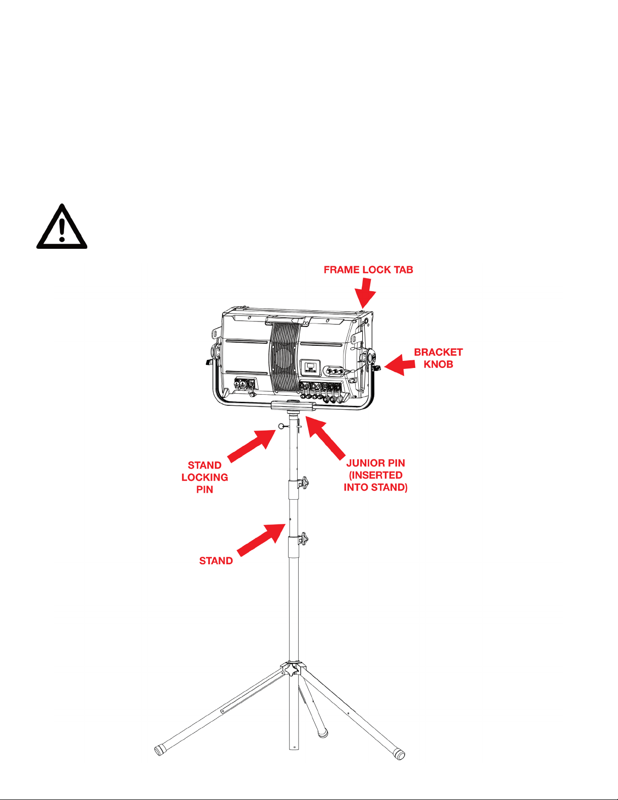
STAND MOUNT INSTALLATION
This device is capable of being stand mounted by following the steps below:
1. Install the Junior Pin, as detailed elsewhere in this section.
2. Lock the mounting bracket in place by tightening both bracket knobs.
3. Insert the Junior Pin into the top of the Tripod Stand. Align the through-hole on the
Junior Pin with the holes in the top of the Tripod Stand, then insert the Locking Pin
through the hole and fasten in place.
4. If necessary, loosen the bracket knobs, adjust the fixture to the desired position, then
tighten the bracket knobs to lock the fixture in place. Use caution to prevent the Tripod
Stand from tipping over during adjustment.
DO NOT INSTALL THE FIXTURE WITH THE FRAME LOCK TAB ORIENTED
TOWARDS THE GROUND. Ensure that the xture is mounted with the Frame Lock
Tab engaged, and oriented upwards. If the xture is oriented with the Frame Lock
Tab aimed toward the ground, and it is not engaged, the xture accessory could
slide out and cause damage or injury.
16
Page 17
INSTALLATION INSTRUCTIONS
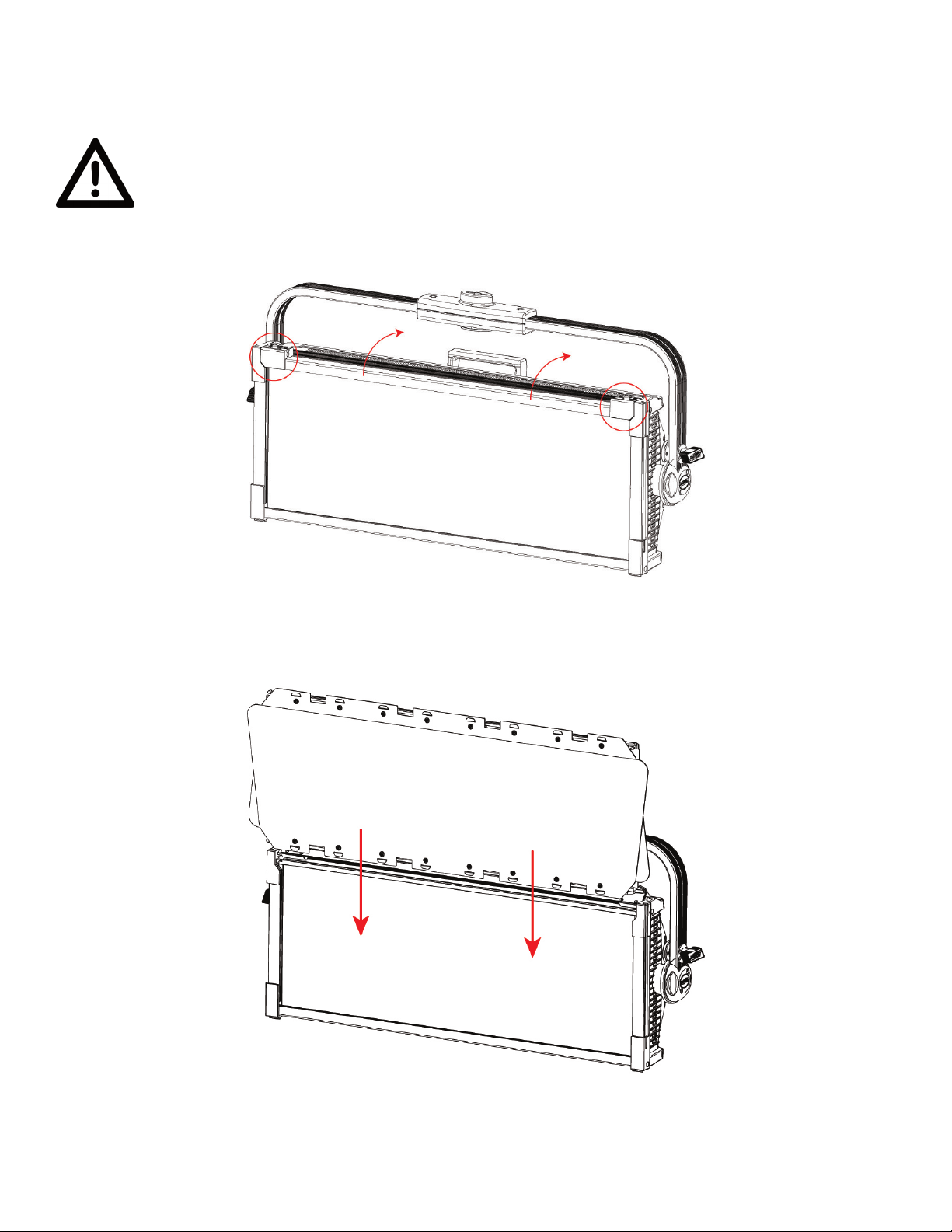
BARN DOOR INSTALLATION
DO NOT INSTALL THE FIXTURE WITH THE FRAME LOCK TAB ORIENTED
TOWARDS THE GROUND. Ensure that the xture is mounted with the Frame Lock
Tab engaged, and oriented upwards. If the xture is oriented with the Frame Lock
Tab aimed toward the ground, and it is not engaged, the xture accessory could
slide out and cause damage or injury.
1. Unlock both frame lock tabs using the latches located on each tab. Flip the top edge of the frame
upward.
2. Look beneath the frame lock tabs and locate the installation slots on the inner edge of
the frame. The slot closest to the front of the device should be vacant. Carefully slide the
barndoor into this slot, then flip down the top edge of the frame and lock the frame lock
tabs back in place.
3. With the barndoors locked securely in place, pull on the tabs at the edges of the barndoor
flaps to deploy the barndoors. Installation is now complete. Please note that the
barndoor accessory must be installed with its own safety cable! Refer to the diagram
in the Fixture Installation section of this manual.
17
Page 18
INSTALLATION INSTRUCTIONS
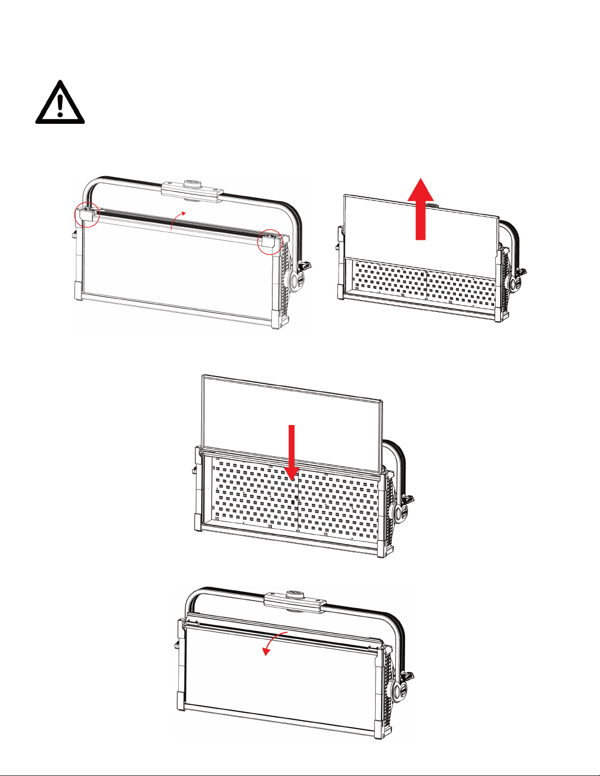
INTENSIFIER LENS INSTALLATION
DO NOT INSTALL THE FIXTURE WITH THE FRAME LOCK TAB ORIENTED
TOWARDS THE GROUND. Ensure that the xture is mounted with the Frame Lock
Tab engaged, and oriented upwards. If the xture is oriented with the Frame Lock
Tab aimed toward the ground, and it is not engaged, the xture accessory could
slide out and cause damage or injury.
1. Unlock both frame lock tabs using the latches located on each tab (circled in the image below).
Flip the top edge of the frame upward. Slide the standard lens upward out of its slot.
2. Slide the Intensifier Lens into the slot. Please note that the Intensifier Lens is NOT
reversible. The forward-facing side of the Intensifier Lens should have a slight ridge
in the lens frame, while the rearward-facing side should have a smooth lens frame.
3. Flip the top edge of the fixture frame back down into place, and lock the frame tabs back
into place. The installation is now complete.
18
Page 19
INSTALLATION INSTRUCTIONS
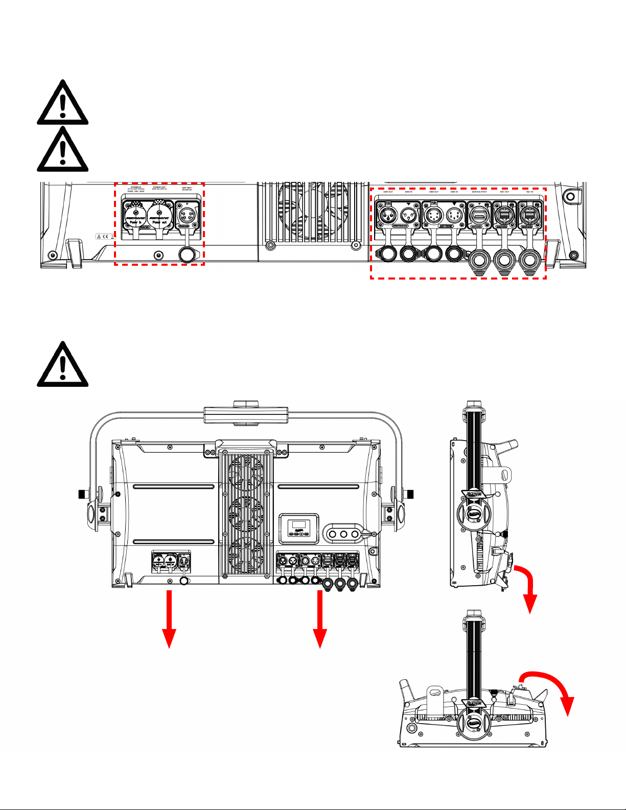
POWER CABLES
ENSURE ALL CONNECTIONS AND ENDCAPS ARE PROPERLY SEALED WITH
DIELECTRIC GREASE (AVAILABLE AT MOST ELECTRICAL SUPPLIERS) TO PREVENT
WATER CORROSION AND/OR ELECTRICAL SHORT CIRCUIT.
TO MAINTAIN THE IP65 RATING INTEGRITY OF THE FIXTURE AND PREVENT WATER
FROM ENTERING THE FIXTURE, SEAL ALL UNUSED CONNECTION RUBBER CAPS.
POWER AND DATA CABLES
TO MAINTAIN THE IP65 RATING INTEGRITY OF THE FIXTURE, RUN ALL CABLES
TOWARDS THE GROUND TO PREVENT WATER ACCUMULATION AROUND THE
CONNECTIONS.
19
Page 20
INSTALLATION INSTRUCTIONS
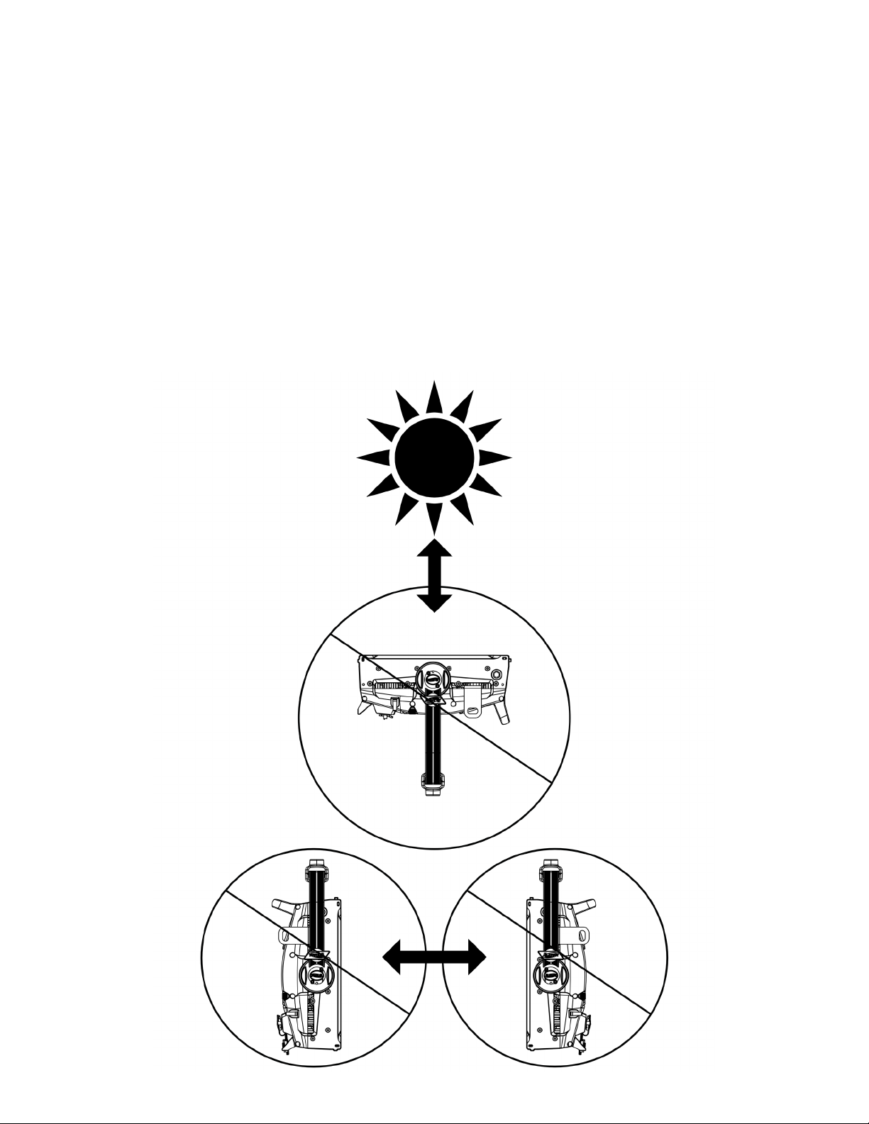
POTENTIAL INTERNAL FIXTURE DAMAGE FROM EXTERNAL SOURCES OF LIGHT BEAMS
External sources of light beams from direct sunlight, lighting moving head xtures, and lasers,
which are focused directly towards the exterior housing and/or penetrate the front lens
opening of ELATION lighting xtures, can cause severe internal damage including burning to
optics, dichroic color lters, glass and metal gobos, prisms, animation wheels, frost lters, iris,
shutters, motors, belts, wiring, discharge lamps, and LEDs.
This issue is not specic only to ELATION lighting xtures, it is a common issue with lighting
xtures from all manufacturers. Although there is no true way to fully prevent this issue from
happening, the guidelines below can prevent any potential damage from occurring if followed.
Contact ELATION Service for more details.
DO NOT EXPOSE THE FIXTURE AND/OR FRONT LENS OPENING TO LIGHT BEAMS FROM
DIRECT SUNLIGHT, OTHER LIGHTING MOVING HEAD FIXTURES, AND LASERS WHILE
UNPACKING, INSTALLATION, USE, AND EXTENDED IDLE TIMES OUTDOORS. DO NOT FOCUS
A LIGHT BEAM FROM ONE LIGHTING FIXTURE DIRECTLY TOWARDS ANOTHER.
20
Page 21
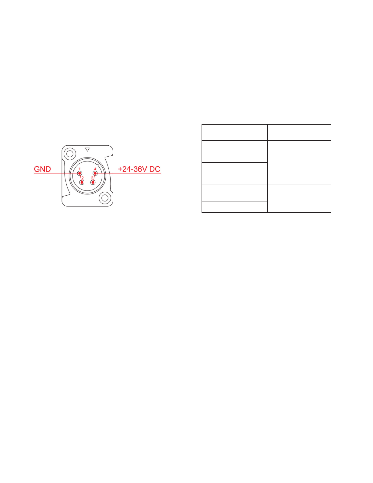
BATTERY CONNECTION
This device is capable of receiving power from a battery pack.
NOTICE: The user is responsible for ensuring compatibility between the device and the
battery pack. Always ensure that the output specifications, operating conditions, and
connection pinouts of the battery pack match the device requirements.
The device features a 4-pin XLR connector for battery power. The connector is located on
the back of the device, next to the DMX In/Out connectors, and is covered with a dust cap.
BE CAREFUL NOT TO CONNECT BATTERY POWER TO ONE OF THE DMX CONNECTORS BY
MISTAKE!
Pinout Diagram
Pin Assignment
1
GND
2
3
+24-36VDC
4
Consult the Safety Guidelines section of this user manual, as well as any safety instructions
included with your battery pack before use or installation.
The device consumes up to 544W when operating all LEDs at full output, which may require
significant battery output to provide the required power. To extend the battery life, it is
possible to reduce the LED power by up to to 50% of maximum output using the “LED Power
Limit” menu in the Personality section of the system menu. Please refer to the System Menu
section of this manual for detailed information.
21
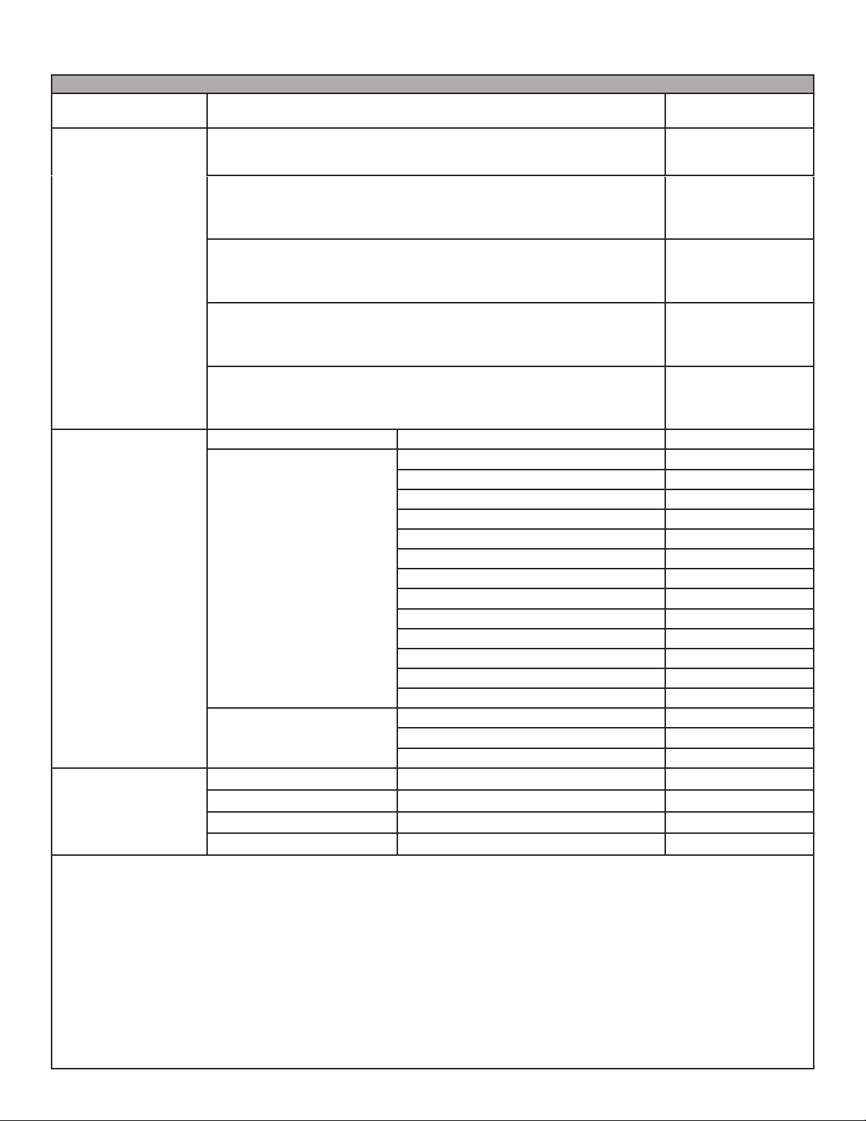
Page 22

SYSTEM MENU
The fixture includes an easy to navigate system menu. The control panel (see image below)
located on the back of the fixture provides access to the main system menu, where all
necessary system adjustments are made. During normal operation, pressing the MODE button
once will access the fixture’s main menu. Once in the main menu, you can navigate through
the different functions and access the sub-menus with the UP and DOWN buttons. Once
you reach a field that requires adjusting, press the ENTER button to activate that field
and use the UP and DOWN buttons to adjust the field. Pressing the ENTER button once
more will confirm your setting. You may exit the main menu at any time without making any
adjustments by pressing the MODE button.
The display screen can be locked by selecting PERSONALITY > DISPLAY > SCREEN LOCK. To
unlock the display screen, simply press and hold the MODE button for three (3) seconds.
A USB FLASH DRIVE CAN BE USED TO UPDATE THE FIXTURE TO THE LATEST
SOFTWARE. Using a USB Flash Drive loaded with the latest software, insert it
into the USB Service Port, then navigate to PERSONALITY/SERVICE, enter the
passcode (050), and select UPDATE SOFTWARE. A copy of the latest software can
be obtained by contacting Elation Support.
AN ELATION E-LOADER III CAN ALSO BE USED TO UPDATE THE FIXTURE TO THE
LATEST SOFTWARE. To order this device, please contact Elation Support for
further details.
ELATION SERVICE USA - Monday - Friday 8:00am to 4:30pm PST
323-582-3322 | Fax 323-832-9142 | support@elationlighting.com
ELATION SERVICE EUROPE - Monday - Friday 08:30 to 17:00 CET
+31 45 546 85 63 | Fax +31 45 546 85 96 | support@elationlighting.eu
22
Page 23
SYSTEM MENU
HOME INTERFACE
SHOW
ENCODER MODE
DMX SETTINGS
STANDALONE
xx CH xxxx
ADDR: 001
Disabled
Int CCT GRN
HSI
Int Color Sat
Manual Control
DMX Address 001 - 512
DMX Mode
No DMX Status
Dimmer 0% - 100%
CCT 2000K - 10000K
Green Shift -100%-0%-100% Default = 0%
Virtual Color Color01 - Color53
ELATION KL Panel XL IP - System Menu
Displays currently
selected DMX mode
Select to run
xture in DMX
control mode
Select to run
xture in CCT
mode with encoder
control
Select to run
xture in HSI
mode with encoder
control
Select to run
xture in Color
mode with encoder
control
Select to run
xture in manual
control mode with
encoder control
1Ch Dimmer
4Ch Dimmer Color
7Ch Dimmer Color FX
6Ch RGBWLC
12Ch RGBWLC 16bit
48Ch RGBWLC Cells
96Ch RGBWLC Cells 16bit
24CH RGB Cells
14Ch Standard
23Ch Extended
58Ch Extended Cells
4Ch HSI
12Ch HSI Ex
Hold Last
Fade to Black
Standalone
23
Page 24

SYSTEM MENU
Primary On / O
Secondary On / O
Select Signal
Dim Mode
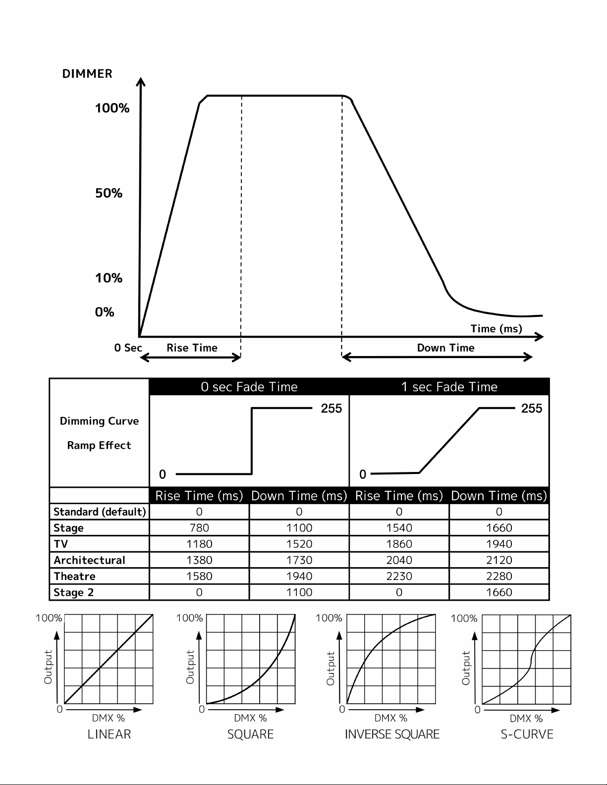
Dim Curves
E-Fly Setting
LED Refresh Rate
LED Power Limit 50%, 60%, 70%, 80%, 90%, 100%
PERSONALITY
Fan Mode Auto, Silent, High
Display
Network
Service Passcode=050
ELATION KL Panel XL IP - System Menu
DMX or E-Fly
E-Fly and DMX Out
Standard
Stage
TV
Architectural
Theatre
Stage 2
Dim Speed 0s - 10s Default = 0.0 s
Linear
Square
Square Inverse
S-Curve
E-Fly Setting
Set Channel
Enable E-Fly Yes / No
900Hz - 1500Hz (1200Hz),
2500Hz, 4000Hz, 5000Hz, 6000Hz,
10KHz, 15KHz, 20KHz, 25KHz
Display
Screen
Delay
Display
Screen
Lock
Rotate Display
Switch
Universe
IP: 002.000.000.002
Subnet: 255.000.000.000
Protocol
00 - 14
10s - 5min
(default = 1min)
O, 10s - 5min
Yes / No / Auto
On / O
0 - 255
ArtNet / KlingNet
/ sACN
Calibration
Update Software
(USB Update)
Factory Restore
Edit RDM UID xxxxxx
Default = 1200 Hz
Display returns to
home screen after
30s of inactivity
Red: 50 - 255
Green: 50 - 255
Blue: 50 - 255
...
Yes / No
Yes / No
24
Page 25

SYSTEM MENU
Life Time xxxxxx hrs
Last Run Time xxxxxx hrs
Time Reset Passcode = 038
Temperature
INFORMATION
DMX Values
Product IDs
Error Logs Fixture Errors
Reset Error Log No / Yes Passcode = 050
Software Verson Vx.x.x
ELATION KL Panel XL IP - System Menu
Total xture
run time, not
resettable
Fixture run time,
resettable
Reset Last Run
Time
Current
Max Resettable
Reset (passcode = 038)
R: xxx
G: xxx
B: xxx
...
Max Address xxx-xxx-xxx...
RDM UID xxxxxx...
None
None
25
Page 26

MANUAL MODE
ENCODER KNOB DESIGNATIONS
Knob 1 Knob 2 Knob 3
INT CCT GRN (INTENSITY, COLOR TEMPERATURE, GREEN SHIFT)
Encoder
Knob
1 Intensity Intensity 0 - 100% 1% 0%
2 Color Temperature CCT 2000 - 10000K 100K 6000K
3 Green Shift GRN -100% - +100% 1% Neutral
HSI (HUE, SATURATION, INTENSITY)
Encoder
Knob
1 Intensity Intensity 0 - 100% 1% 0%
2 Color Temperature CCT 2000 - 10000K 100K 6000K
3 Green Shift GRN -100% - +100% 1% Neutral
INT COL SAT (INTENSITY, COLOR, SATURATION)
Encoder
Knob
1 Intensity Intensity 0 - 100% 1% 0%
2 Color White, Virtual Color 1, 2, 3... Single Color White
3 Saturation Sat 0 - 100% 1% 100%
Parameter Display
Parameter Display
Parameter Display Resolution/Steps Default
Resolution/
Steps
Resolution/
Steps
Default
Default
MANUAL
Encoder
Knob
1 Intensity Intensity 0 - 100% 1% 0%
2
3 Setting Selection [Setting Name] 0 - 255
Parameter Display Resolution/Steps Default
Setting
Adjustment
[Setting Name] 0 - 255 1 0
Strobe / Red /
Green / Blue /
White / Lime /
Cyan
26
Strobe
Page 27

DMX TRAITS: CHANNEL FUNCTIONS & VALUES
Features subject to change without notice
MODE/CHANNEL
7CH
1CH
Dimmer
4CH
Dim
Dim
Color
Color
1 1 1 2 2 2 1 2 0-255 Dimmer: Intensity 0 to 100%
FX
2 2 3 3 3 2 3 0-255 Dimmer Fine: Dimmer ne
3 3 7 16 3 6
4 4 9 18 5 7
12CH
6CH
RGB
RGB
WLC
WLC
16bit
1 1 4 4 0-255 Red: 0 to 100%
2 5 0-255 Red Fine: 0 to 100%
2 3 5 6 0-255 Green: 0 to 100%
4 7 0-255 Green Fine: 0 to 100%
3 5 6 8 0-255 Blue: 0 to 100%
6 9 0-255 Blue Fine: 0 to 100%
4 7 10 0-255 White: 0 to 100%
8 11 0-255 White Fine: 0 to 100%
5 9 12 0-255 Lime: 0 to 100%
10 13 0-255 Lime Fine: 0 to 100%
6 11 14 0-255 Cyan: 0 to 100%
12 15 0-255 Cyan Fine: 0 to 100%
48CH
RGB
WLC
Cells
96CH
RGB
WLC
Cells
16bit
24CH
RGB
Cells
23CH
Ext
58CH
Ext
Cells
4CH
HSI
3 4 0-255 Hue: 0 to 100%
4 5 0-255 Saturation: 0 to 100%
14CH
Sta
1 1 1 1
8 17 4
12CH
HSI
EXT
VALUE FUNCTION
Shutter, strobe:
0-31 Shutter closed
32-63 shutter open
64-95 Strobe eect
96-127 shutter open
128-159 Pulse-eect
160-191 shutter open
192-223 Random strobe
224-255 shutter open
CCT: 0 to 100%
0-19 Open
20-100 2000K -10000K
101-255 10000K
Green Shift: 0 to 100%
0 Idle
1-127 Reddish to neutral
128 neutral
129-255 neutral to Green
Color Wheel:
0 Open
1-60 Virtual Swatch Book
Color Scroll
180-200 Clockwise fast→slow
201-208 Stop
209-229 Counterclockwise slow→ fast
230-234 Open
Random Slots
235-239 Fast
240-244 Medium
245-249 Slow
250-255 Open
27
Page 28

DMX TRAITS: CHANNEL FUNCTIONS & VALUES
Features subject to change without notice
MODE/CHANNEL
1CH
Dimmer
4CH
Dim
Color
7CH
Dim
Color
FX
6CH
RGB
WLC
12CH
RGB
WLC
16bit
48CH
RGB
WLC
Cells
96CH
RGB
WLC
Cells
16bit
24CH
RGB
Cells
23CH
Ext
58CH
Ext
Cells
4CH
HSI
14CH
Sta
10 19 6 8
11 20 7 9
12CH
HSI
EXT
VALUE FUNCTION
Dim Modes
0-20 Standard
21-40 Stage
41-60 TV
61-80 Architectural
81-100 Theatre
101-120 Stage 2
Dimmer Delay Time
121 0s
122 0.1s
123 0.2s
124 0.3s
125 0.4s
126 0.5s
127 0.6s
128 0.7s
129 0.8s
130 0.9s
131 1.0s
132 1.5s
133 2.0s
134 3.0s
135 4.0s
136 5.0s
137 6.0s
138 7.0s
139 8.0s
140 9.0s
141 10s
142-255 Idle
Control:
0-29 Idle
30-39 Fan Mode Auto
40-49 Fan Mode Silent
50-59 Fan Mode High
60-79 Idle
80-84 Reset
85-99 Idle
100-168 Refresh Rate (Hz)
100 900
101 910
102 920
103 930
104 940
105 950
106 960
107 970
108 980
109 990
110 1000
111 1010
112 1020
113 1030
114 1040
28
Page 29

DMX TRAITS: CHANNEL FUNCTIONS & VALUES
Features subject to change without notice
MODE/CHANNEL
4CH
Dim
Color
7CH
Dim
Color
FX
6CH
RGB
WLC
12CH
RGB
WLC
16bit
48CH
RGB
WLC
Cells
96CH
RGB
WLC
Cells
16bit
24CH
RGB
Cells
23CH
Ext
58CH
Ext
Cells
4CH
HSI
14CH
Sta
11 20 7 9
12CH
HSI
EXT
VALUE FUNCTION
115 1050
116 1060
117 1070
118 1080
119 1090
120 1100
121 1110
122 1120
123 1130
124 1140
125 1150
126 1160
127 1170
128 1180
129 1190
130 1200
131 1210
132 1220
133 1230
134 1240
135 1250
136 1260
137 1270
138 1280
139 1290
140 1300
141 1310
142 1320
143 1330
144 1340
145 1350
146 1360
147 1370
148 1380
149 1390
150 1400
151 1410
152 1420
153 1430
154 1440
155 1450
156 1460
157 1470
158 1480
159 1490
160 1500
161 2500
162 4000
163 5000
164 6000
165 10000
166 15000
167 20000
168 25000
29
Page 30

DMX TRAITS: CHANNEL FUNCTIONS & VALUES
Features subject to change without notice
MODE/CHANNEL
96CH
48CH
RGB
RGB
WLC
Cells
1 1 1 11 0-255 Red 1: 0 to 100%
2 3 2 12 0-255 Green 1: 0 to 100%
3 5 3 13 0-255 Blue 1: 0 to 100%
4 7 14 0-255 White 1: 0 to 100%
24CH
RGB
Cells
14CH
Sta
11 20 7 9
WLC
Cells
16bit
2 0-255 Red 1 Fine: 0 to 100%
4 0-255 Greeen 1 Fine: 0 to 100%
6 0-255 Blue 1 Fine: 0 to 100%
8 0-255 White 1 Fine: 0 to 100%
9 15 0-255 Lime 1: 0 to 100%
10 0-255 Lime 1 Fine: 0 to 100%
11 16 0-255 Cyan 1: 0 to 100%
12 0-255 Cyan 1 Fine: 0 to 100%
23CH
Ext
58CH
Ext
Cells
4CH
HSI
12CH
HSI
EXT
VALUE FUNCTION
169-200 No Function
201-210 Linear
211-220 Square
221-230 Inverse Square
231-240 S-Curve
241 program1 (Scene 1-8)
242 program2 (Scene 9-16)
243 program3 (Scene 17-24)
244 program4 (Scene 25-32)
245 program5 (Scene 33-40)
246 program6 (Scene 41-48)
247 program7 (Scene 49-56)
248-255 No Function
FX Oset
0 Idle
1 Fixture Oset 10 Degree
2 Fixture Oset 20 Degree
3-34 Fixture Oset…
35 Fixture Oset 350 Degree
36 Syncronized
37-100 No Function
101–120 Random Fixture Oset
121-140 Random Pixel Order
141-255 Random Steps
1CH
Dimmer
4CH
Dim
Color
7CH
Dim
Color
FX
5 12 21 8 10 0-255 FX: See Table
6 13 22 9 11 0-255 FX Adjust: See Table
7 14 23 10 12
6CH
RGB
WLC
12CH
RGB
WLC
16bit
43 85 53 0-255 Red 8: 0 to 100%
86
44 87 54 0-255 Green 8: 0 to 100%
88 0-255 Greeen 8 Fine: 0 to 100%
45 89 55 0-255 Blue 8: 0 to 100%
90 0-255 Blue 8 Fine: 0 to 100%
46 91 56 0-255 White 8: 0 to 100%
92 0-255 White 8 Fine: 0 to 100%
47 93 57 0-255 Lime 8: 0 to 100%
94 0-255 Lime 8 Fine: 0 to 100%
48 95 58 0-255 Cyan 8: 0 to 100%
96 0-255 Cyan 8 Fine: 0 to 100%
0-255
Red 8 Fine: 0 to 100%
30
Page 31

DMX TRAITS: FX TABLE
Type Slot DMX Name FX Adjustment Notes/Steps Color Mix
0 OFF
Onyx Bank 25 Fader 1
and 2
Onyx Bank 25 Fader 4
and 5
Onyx Bank 25 Fader 7
in Red
Onyx Bank 25 Fader 7 in
Red and White
Onyx Bank 25 Fader 7 in
Amber
Onyx Bank 26 Fader 8 no
fade
Onyx Bank 26 Fader 9 no
fade
Cyan/Magenta/Yellow/
Red/Green/Blue Fade
Cyan/Magenta/Yellow/
Red/Green/Blue Step
Emergency
Color Party
1 2 Red Blue Police Speed
2 2
3 3 RBA Police Speed
4 4 RBA Burst Police Speed Onyx Bank 25 Fader 6 Ignore
5 5 Blue Police Speed Onyx Bank 25 Fader 7 Ignore
6 6 Red Fire Speed
7 7 Red White Fire Speed
8 8 Roadside Emergency Speed
9 9
10 10
11 11
12 12
13 13
14 14
15 15
16 16
17 17
18 18
19 19
20 20
21 21 Party Lights Speed Onyx Bank 27 Fader 1 Ignore
22 22 Party with Strobe Speed Onyx Bank 27 Fader 2 Ignore
23 23 Disco Speed tbd Ignore
24 24 Disco 2 Speed tbd Ignore
25 25 Rave Speed tbd Ignore
26 26 Rave 2 Speed tbd Ignore
27 27
28 28
29 29
30 30 CMY Wave Speed Onyx Bank 26 Fader 8 Ignore
31 31 CMY Step Speed
32 32 RGB Wave Speed Onyx Bank 26 Fader 9 Ignore
33 33 RGB Step Speed
34 34 CMYRGB Wave Speed
35 35 CMYRGB Step Speed
36 36
37 37
38 38
39 39
40 40
Red Blue Burst
Police
Speed Onyx Bank 25 Fader 3 Ignore
Ignore
Ignore
Ignore
Ignore
Ignore
Ignore
Ignore
Ignore
Ignore
31
Page 32

DMX TRAITS: FX TABLE
Type Slot DMX Name FX Adjustment Notes/Steps Color Mix
41 41 Campre Speed Onyx Bank 25 Fader 8 Ignore
42 42 Candle Speed Onyx Bank 25 Fader 9 Ignore
Onyx Bank 25 Fader
10
Fire
Weather
43 43 Windy Candle Speed
44 44 Large Fire Speed tbd Ignore
45 45
46 46
47 47
48 48
49 49
50 50 Fireworks Color Delay tbd Ignore
51 51 Fireworks White Delay tbd Ignore
52 52 Fireworks Combo Delay tbd Ignore
53 53
54 54
55 55
56 56
57 57
58 58
59 59
60 60
61 61 Lightning 1 Delay Onyx Bank 26 Fader 1 Use
62 62 Lightning 2 Delay Onyx Bank 26 Fader 2 Use
63 63 Lightning 3 Delay Onyx Bank 26 Fader 3 Use
64 64
65 65
66 66
67 67
68 68
69 69
70 70
71 71 Clouds Speed Onyx Bank 26 Fader 4 Use
72 72
73 73
74 74
75 75
76 76
77 77
78 78
79 79
80 80
Ignore
32
Page 33
DMX TRAITS: FX TABLE
Type Slot DMX Name FX Adjustment Notes/Steps Color Mix
81 81 Paparazi 1 Speed Onyx Bank 26 Fader 5 Use
82 82 Paparazi 2 Speed Onyx Bank 26 Fader 6 Use
83 83 Paparazi 3 Speed Onyx Bank 26 Fader 7 Use
84 84
85 85
86 86
87 87
88 88
89 89
Onyx Bank 27 Fader
10
Flashes
90 90 Film Projector Speed
91 91 TV Flicker Speed tbd Use
92 92 Welding Speed tbd Ignore
93 93 Flourescent Speed tbd Use
94 94
95 95
96 96
97 97
98 98
99 99
100 100
101-255 101-255
Use
DMX TRAITS: FX ADJUST TABLE
Value Function
Speed
0-5 Stop
6-255 0.1 - 10Hz
Delay
0-5 Idle
6-10 One Time FX
11-110 Delay 0.1s to 10s
111-210 Random Delay 0.1s to 10s
211-255 Idle
33
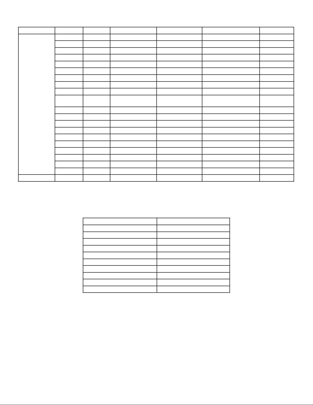
Page 34

COLOR TEMPERATURE
DMX VALUE COLOR TEMPERATURE (K) DMX VALUE COLOR TEMPERATURE (K)
20 2000 61 6100
21 2100 62 6200
22 2200 63 6300
23 2300 64 6400
24 2400 65 6500
25 2500 66 6600
26 2600 67 6700
27 2700 68 6800
28 2800 69 6900
29 2900 70 7000
30 3000 71 7100
31 3100 72 7200
32 3200 73 7300
33 3300 74 7400
34 3400 75 7500
35 3500 76 7600
36 3600 77 7700
37 3700 78 7800
38 3800 79 7900
39 3900 80 8000
40 4000 81 8100
41 4100 82 8200
42 4200 83 8300
43 4300 84 8400
44 4400 85 8500
45 4500 86 8600
46 4600 87 8700
47 4700 88 8800
48 4800 89 8900
49 4900 90 9000
50 5000 91 9100
51 5100 92 9200
52 5200 93 9300
53 5300 94 9400
54 5400 95 9500
55 5500 96 9600
56 5600 97 9700
57 5700 98 9800
58 5800 99 9900
59 5900 100-255 10000
60 6000
34
Page 35
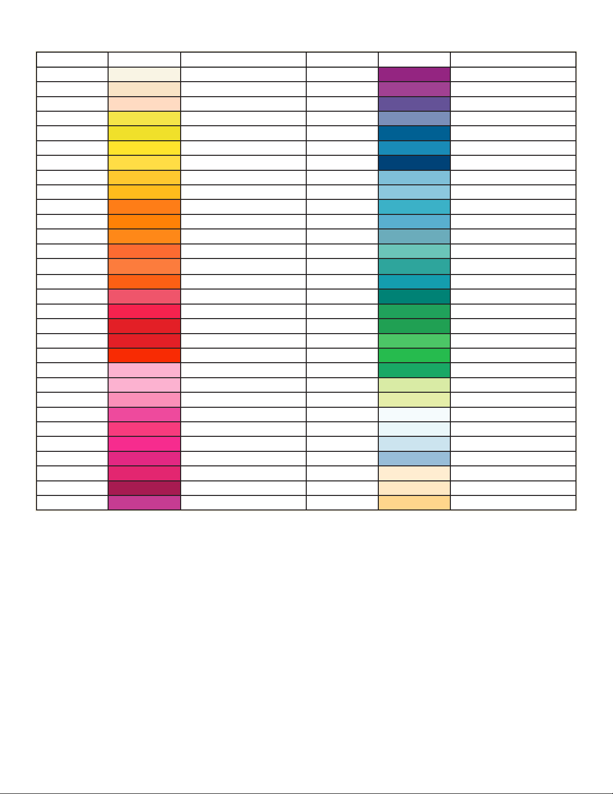
VIRTUAL SWATCH BOOK
VALUE FILTER # COLOR VALUE FILTER # COLOR
1 7 pale yellow 31 126 Mauve
2 103 straw 32 49 Medium Purple
3 151 gold tint 33 58 Lavender
4 100 spring yellow 34 199 Palace Blue
5 10 medium yellow 35 119 Dark Blue
6 101 yellow 36 132 Medium Blue
7 104 deep amber 37 120 Deep Blue
8 15 deep straw 38 165 Daylight Blue
9 179 loving amber 39 161 Slate Blue
10 21 gold amber 40 118 Light Blue
11 105 orange 41 68 Sky Blue
12 158 deep orange 42 143 Pale Navy Blue
13 22 dark amber 43 131 Marine Blue
14 778 millennium gold 44 115 Peacock Blue
15 135 deep golden amber 45 172 Lagoon Blue
16 24 scarlet 46 116 Medium Blue Green
17 106 primary red 47 90 Dark Yellow Green
18 26 bright red 48 139 Primary Green
19 27 medium red 49 122 Fern Green
20 19 re 50 89 Moss Green
21 157 pink 51 124 Dark Green
22 36 medium pink 52 88 Lime Green
23 111 dark pink 53 138 Pale Green
24 128 bright pink 54 203 Quarter CT Blue
25 148 bright rose 55 202 Half CT Blue
26 332 special rose pink 56 201 FULL CT Blue
27 793 vanity fair 57 200 Double CT Blue
28 113 Magenta 58 206 Quarter CT Orange
29 46 Dark Magenta 59 205 Half CT Orange
30 48 Rose Purple 60 204 FULL CT Orange
35
Page 36
REMOTE DEVICE MANAGEMENT (RDM)
NOTE: In order for RDM to work properly, RDM enabled equipment must be used throughout
the entire system, including DMX data splitters and wireless systems.
Remote Device Management (RDM) is a protocol that sits on top of the DMX512 data standard
for lighting, allowing the DMX systems of the device to be managed, modified, and monitored
remotely (hence, remote device management). This protocol is ideal for fixtures installed in
locations that are not easily accessible.
With RDM, the DMX512 system becomes bi-directional, allowing a compatible RDM enabled
controller to send out a signal to devices on the wire, as well as allowing the fixture to
respond (known as a GET command). The controller can then use it’s SET command to modify
settings that would typically have to be changed or viewed directly via the unit’s display
screen, including the DMX Address, DMX Channel Mode, and Temperature Sensors.
FIXTURE RDM INFORMATION:
RDM Code Device ID Device Model ID Personality ID
001 01CH DIMMER
002 04CH DIMMER COLOR
003 07CH DIMMER COLOR FX
004 06CH RGBWLC
005 12CH RGBWLC 16BIT
006 24CH RGB CELLS
22A6 002C 44
007 48CH RGBWLC CELLS
008 96CH RGBWLC CELLS 16BIT
009 14CH STANDARD
010 23CH EXTENDED
011 58CH EXTENDED CELLS
012 04CH HSI
013 12CH HSI EXTENDED
Please be aware that not all RDM devices support all RDM features, and therefore it is
important to check beforehand to ensure that the equipment that you are considering includes
all of the features that you require.
The following parameters are accessible in RDM on this device:
ELATION KL PANEL XL IP RDM PARAMETERS
PROXIED_DEVICE_COUNT
SENSOR_DEFINITION,
SENSOR_VALUE,
DEVICE_MODEL_DESCRIPTION,
MANUFACTURER_LABEL,
DEVICE_LABEL,
DMX_PERSONALITY,
DMX_PERSONALITY_DESCRIPTION,
DEVICE_HOURS,
COMMS_STATUS,
STATUS_ID_DESCRIPTION,
CLEAR_STATUS_ID,
LAMP_HOURS,
LAMP_STRIKES,
LAMP_STATE,
LAMP_ON_MODE,
DEVICE_POWER_CYCLES,
DISPLAY_INVERT,
DISPLAY_LEVEL,
REAL_TIME_CLOCK,
POWER_STATE,
PRESET_PLAYBACK,
DEFAULT_SLOT_VALUE,
LANGUAGE,
LANGUAGE_CAPABILITIES,
BOOT_SOFTWARE_VERSION_LABEL,
BOOT_SOFTWARE_VERSION_ID,
PRODUCT_DETAIL_ID_LIST
STATUS_MESSAGES
36
Page 37

ERROR CODES
Error Codes subject to change without notice
ERROR CODES DESCRIPTION
Temp Er
Displays if xture overheats.
REFRESH RATE
DMX Values
100 900 135 1250
101 910 136 1260
102 920 137 1270
103 930 138 1280
104 940 139 1290
105 950 140 1300
106 960 141 1310
107 970 142 1320
108 980 143 1330
109 990 144 1340
110 1000 145 1350
111 1010 146 1360
112 1020 147 1370
113 1030 148 1380
114 1040 149 1390
115 1050 150 1400
116 1060 151 1410
117 1070 152 1420
118 1080 153 1430
119 1090 154 1440
120 1100 155 1450
121 1110 156 1460
122 1120 157 1470
123 1130 158 1480
124 1140 159 1490
125 1150 160 1500
126 1160 161 2500
127 1170 162 4000
128 1180 163 5000
129 1190 164 6000
130 1200 165 10000
131 1210 166 15000
132 1220 167 20000
133 1230 168 25000
134 1240
Refresh Rate (Hz
)
DMX Values
Refresh Rate (Hz)
37
Page 38
DIMMER MODES / DIMMER CURVES
38
Page 39

39
Page 40
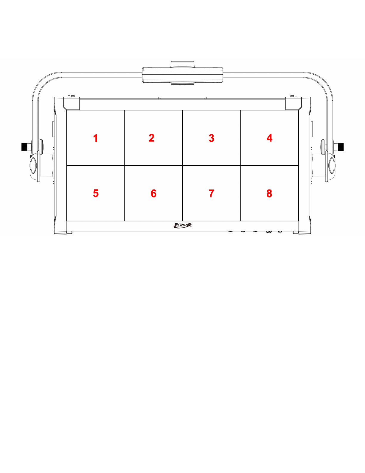
PIXEL ZONES
40
Page 41

SPECIFICATIONS
SOURCE
6-in-1 (Red, Green, Blue, White, Lime, Cyan) Full Spectrum LED Array
50,000 Hour Average LED Life*
*Test lab conditions. May vary depending on several factors including but not limited to:
Environmental Conditions, Power/Voltage, Usage Patterns (On-O Cycling), Control, and Dimming.
PHOTOMETRIC DATA
up to 40,000 Total Lumen Output
EFFECTS
Variable CCT 2,000K - 10,000K
Green-Shift Adjustment
4x2 Section Control
Virtual Gel Library
Variable 16-bit Dimming Curve Modes
High Speed Electronic Shutter and Strobe
Remote Adjustable LED Refresh Rate Frequency
(900-25kHZ)
CONTROL / CONNECTIONS
13 DMX Channel Modes (1-96 Ch.)
1 or 8 cell control sections
3 Manual Adjustment Encoders
4 Button Control Panel and OLED Menu Display
DMX, RDM, Art-NET, sACN Protocol Support
E-FLY™ Internal Extended Range Wireless DMX Transceiver
Locking 5pin XLR Connector In/Out
Locking 3pin XLR Connector In/Out
Locking IP65 Power Connector In
USB Connection (Firmware Updates, External 5V power for accessories)
4pin XLR External Battery Connection (battery not included)
SIZE / WEIGHT
Length: 6.7” (169.1mm)
Width: 32.9” (836mm)
Height: 18.4” (466.6mm)
Weight: 51.4 lbs. (23.3 kg)
Weight: (Junior Pin) 1.02 lbs. (0.46 kg)
ELECTRICAL / THERMAL
AC 100-240V - 47/63Hz
24-36 VDC (battery operation - battery not included)
Max Power Consumption 681W
14°F to 113°F (-10°C to 45°C)
BTU/hr (+/- 10%) 2138.34
APPROVALS / RATINGS
CE | cETLus | IP65
Specications and documentation subject to change without notice.
41
Page 42

DIMENSIONAL DRAWINGS
FIXTURE ONLY
6.7in.
[169.1mm]
5.7in.
[145.6mm]
23.9in. [606mm]
26.4in. [670mm]
30.7in. [780mm]
32.9in. [836mm]
18.4in. [466.6mm]
14.7in. [374.5mm]
11.6in. [295.6mm]
13.5in. [342.6mm]
BARNDOORS INSTALLED
14.7in. [374.5mm]
14.9in. [378.6mm]
7.1in.
[181.5mm]
42
Page 43

OPTIONAL ACCESSORIES
ORDER CODE ITEM
KLP115
1237000263
KLP972 KL Panel XL IP Intensier Lens
KLP637 KL Panel XL IP Egg Crate
KL Panel XL IP (US SKU)
KL Panel XL IP (EU SKU)
FCC STATEMENT
This device complies with Part 15 of the FCC Rules. Operation is subject to the following two
conditions: (1) this device may not cause harmful interference, and (2) this device must accept
any interference received, including interference that may cause undesired operation.
FCC RADIO FREQUENCY INTERFERENCE WARNINGS & INSTRUCTIONS
This product has been tested and found to comply with the limits as per Part 15 of the FCC
Rules. These limits are designed to provide reasonable protection against harmful interference
in a residential installation. This device uses and can radiate radio frequency energy and, if not
installed and used in accordance with the included instructions, may cause harmful interference
to radio communications. However, there is no guarantee that interference will not occur in
a particular installation. If this device does cause harmful interference to radio or television
reception, which can be deter- mined by turning the device o and on, the user is encouraged
to try to correct the interference by one or more of the following methods:
• Reorient or relocate the device.
• •ncrease the separation between the device and the receiver.
• Connect the device to an electrical outlet on a circuit dierent from which the radio
receiver is connected.
• Consult the dealer or an experienced radio/TV technician for help.
Energy Saving Matters (EuP 2009/125/EC)
Saving electric energy is a key to help protecting the environment. Please turn o all electrical
products when they are not in use. To avoid power consumption in idle mode, disconnect all
electrical equipment from power when not in use. Thank you!
43
Page 44

 Loading...