

Page 1
Lumina Matrix
USER MANUAL
40-3402
Page 2
Lumina Matrix LED
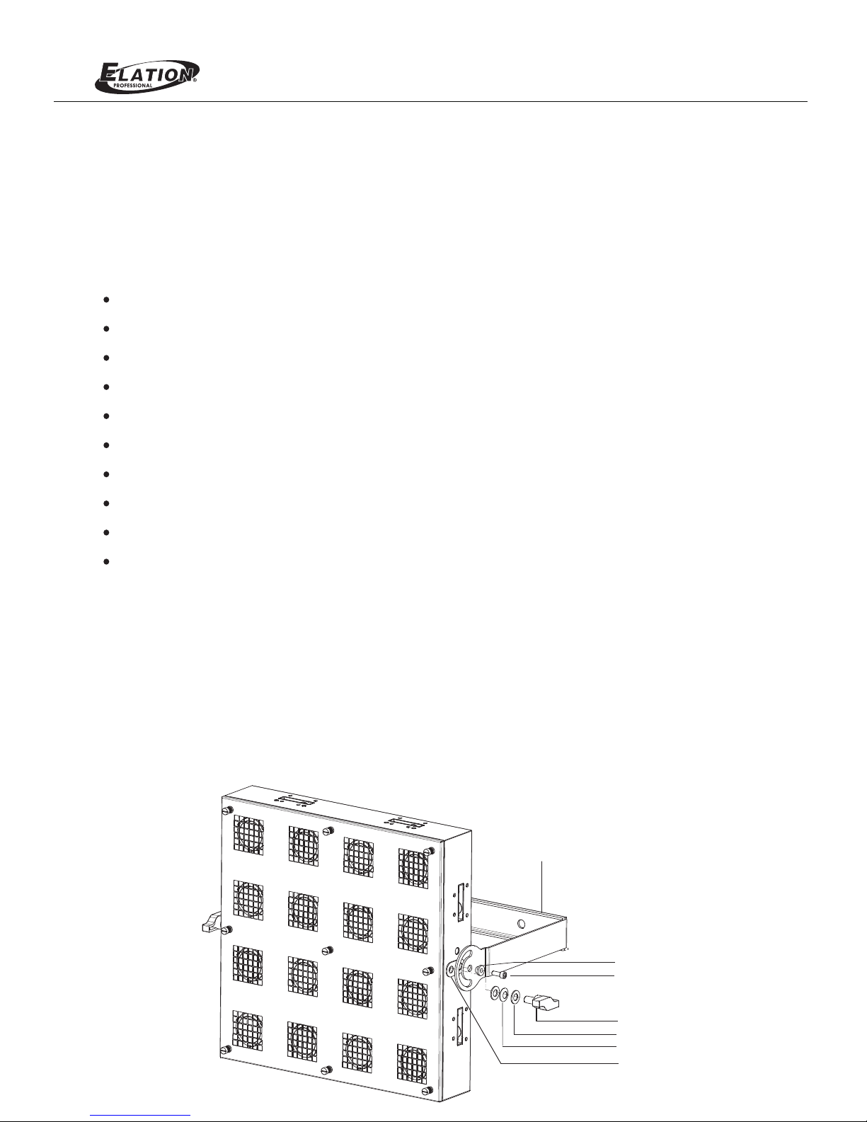
1. The unit power cable (x1) + Yoke Assembly (x1)
2. Axle Bush(x2) + L Type Hexagon Spanner(x1) + M10 Washer(x4)
3. M10*20 S Type Bakelite Screws(x2) + Belleville Washer(x2)
4. M6*12 Screw(x4) + M6*20 Screw(x2) + Profile gasket(x2)
Standard DMX 5-pin In/Out
48 built-in programs except for Auto subject to Speed and Dimmer
0-100% dimming level
Standard DMX-512 protocol
01 Thru 100 Chase Speed adjustment
Power failure memory
MAIN FEATURES
LED display window-shows current activity and function state
On/Off switch
Fuse protection
Accessories(Included):
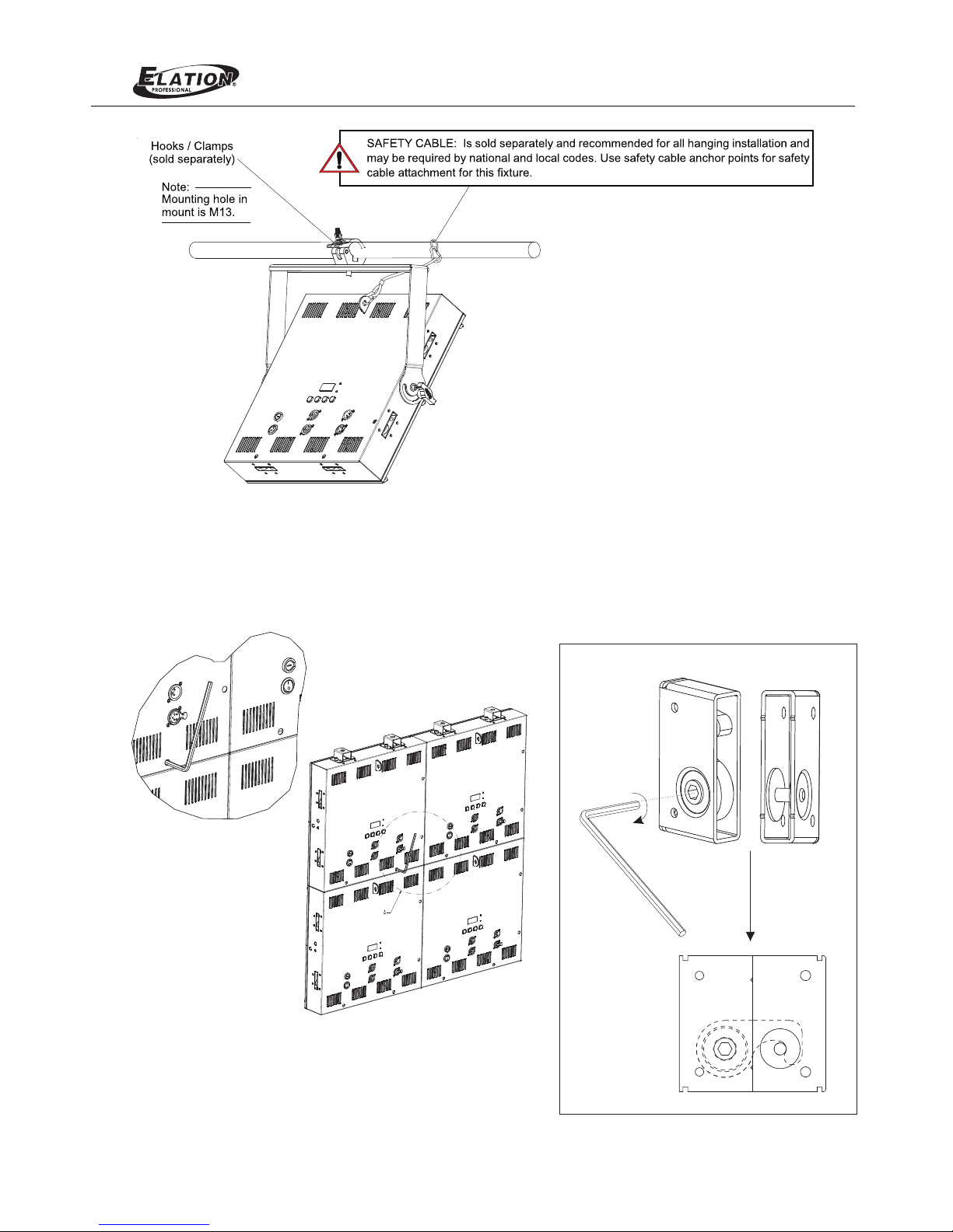
Lumina Matrix LED is provided with the ability to hang via truss hooks, clamps, etc.(sold separately). Simply attach
hook clamp, etc. to the Lumina Matrix LED’s mounts in the provided M13 holes. Before use, make sure the screws are
secured firmly.
INSTALLATION
07, 08, 10, 14, 16, 22 DMX Channels selection
Note :
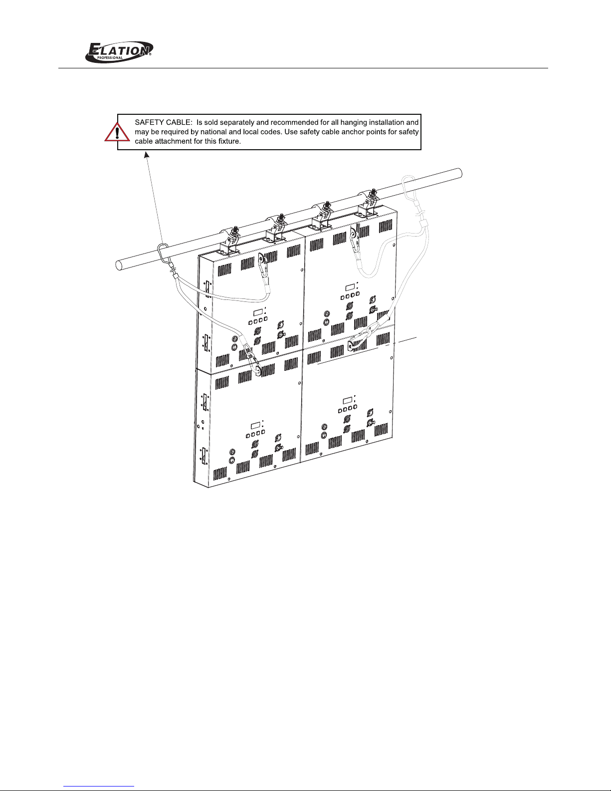
Once this unit is for hanging application, it is required to use a safety rope (sold separately, which can hold at least
10 times the weight of the fixture ) to ensure the mounting safety of the fixture by attached through the holder.
Yoke As sem bly (x1)
S Type Bakelite Screw(x2)
M10 Washer(x4)
Belleville Washer(x2)
Profile Gasket (x2)
M6*20 Screw(x2)
Axle Bush(x2)
Page 3
Lumina Matrix LED
GENERAL INSTRUCTIONS
WARNINGS
After use, the front panel is extreme hot. Please wait at least 15 min. for absolute cool before touching it.
Otherwise, it causes the result of burning.
Thanks for your purchasing Elation Lumina Matrix LED lighting equipment, which is available in Warm White
(WW) version. The Lumina Matrix LED is compatible of both DMX & RDM and with 16 channel LED intensity
adjustable. Programs can be updated via RDM interface. It is available in master and slave control connection.
It is easy for users to install and operate.
For the optimum operation and best performance, please read the instruction in this manual carefully and
thoroughly.
This device is not suitable for direct mounting on normally flammable surfaces. To keep a minimum 0.2m
safety distance to any flammable materials.
DO NOT make any inflammable liquids, water or metal objects enter the unit.
This unit contains no user serviceable parts inside. This unit contains dangerous voltages, always remove
the power plug from the wall socket before any service operation and when not in use for a long time.
Earth connection is so essential.
Stop using the unit immediately in the event of serious operation problems and either contact your local
dealer for a check or contact us directly.
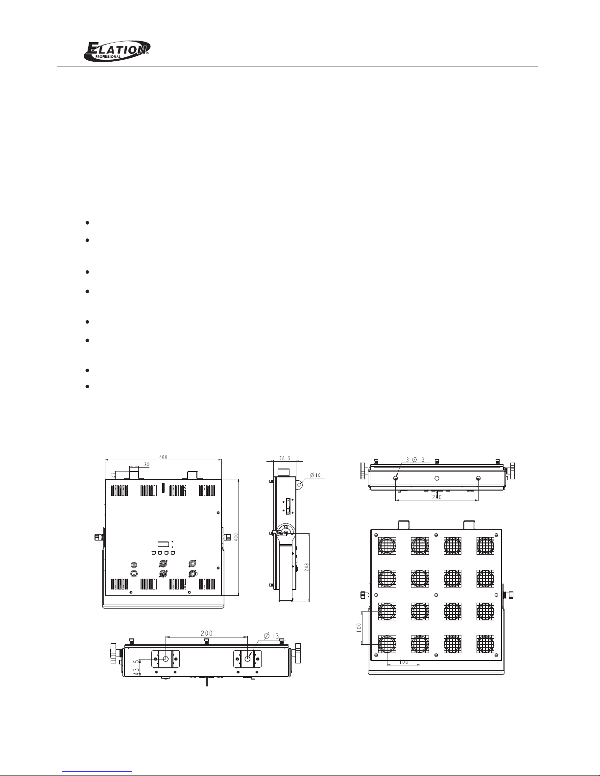
PHYSICAL DIMENSIONS
To protect against high electric shock and injury to person, DO NOT open or dismantle the unit.
NEVER try to repair the unit yourself. Repair by unqualified people could cause damage or mis-operation.
Page 4
Lumina Matrix LED
Lock Details
Multi-Lumina Matrix LEDs can be installed together for hanging application via a L type spanner(included). Line up
the products side by side, then insert the L type spanner into the mounting hole on the back of the product, and then
turn the L type spanner in clockwise, the products will be locked together. (see the illustrations as below)
WARNI NG! Never install over 5 units t ogether in a vert ical row. Or else, t here will be over weight danger.
Fasten
Page 5
Lumina Matrix LED
Page 6
Lumina Matrix LED
Fuses:
The Lumina Matrix LED electric system is protected by T3.15A 250V 5x20mm. Please see the printing on the case
and these fuses prevent you from overloading damaging your unit. To replace the protective fuse, use a flat head
screwdriver to unscrew the fuse holder. Pull out the old fuse and replace it with a new one. Insert the fuse back
into the slot and tighten. Always replace with exact same type fuse removed unless otherwise specified by an
authorized service technician,
Power:
Before plugging your unit in, be sure the resource voltage in your area matches the unit required voltage.
The unit is available in 100-240 VAC. Because the line voltage may vary from venue to venue, you should be
sure to plug the socket into a matching wall outlet before attempting to operate your unit.
SYSTEM CONNECTION
3pi n Power C able
5pi n DMX Cab le
DMX IN
DMX OUT
DMX IN
DMX OUT
DMX IN
DMX OUT
DMX IN
DMX OUT
POW ER IN
DMX I N
Conne ct to 12pcs(AC 100 -120V) / 21p cs( AC230V)
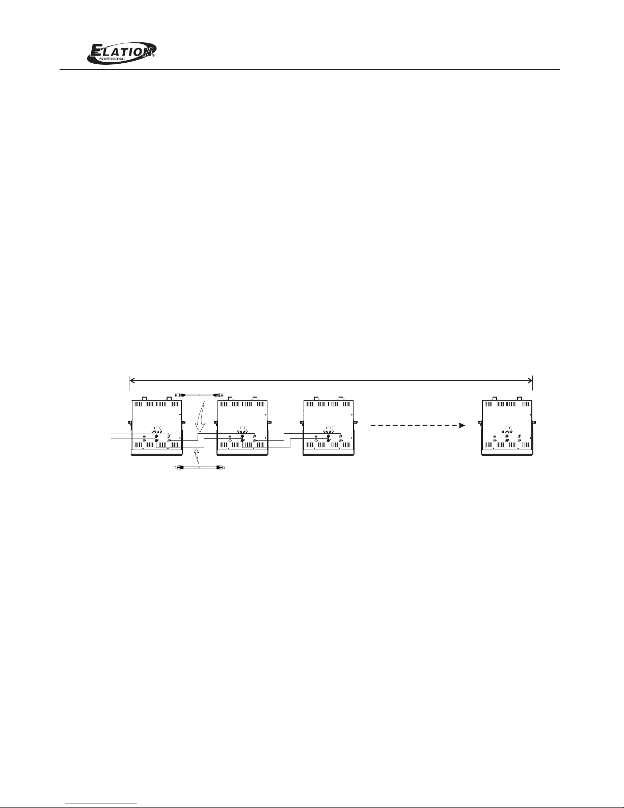
Maximum amount of this units that may be connected is 12pcs(AC100-120V) or 21pcs(220-240V). One universe
DMX candrive up to 32pcs of Lumina Matrix LED, please add DMX booster if Lumina Matrix LEDs are connected
together in line over 32pcs or data cable over 100M. the connections may be illuminated as following.
Page 7
MODE
M NE U
RDM /DMX
POW ER
UP
DOWN
Lumina Matrix LED
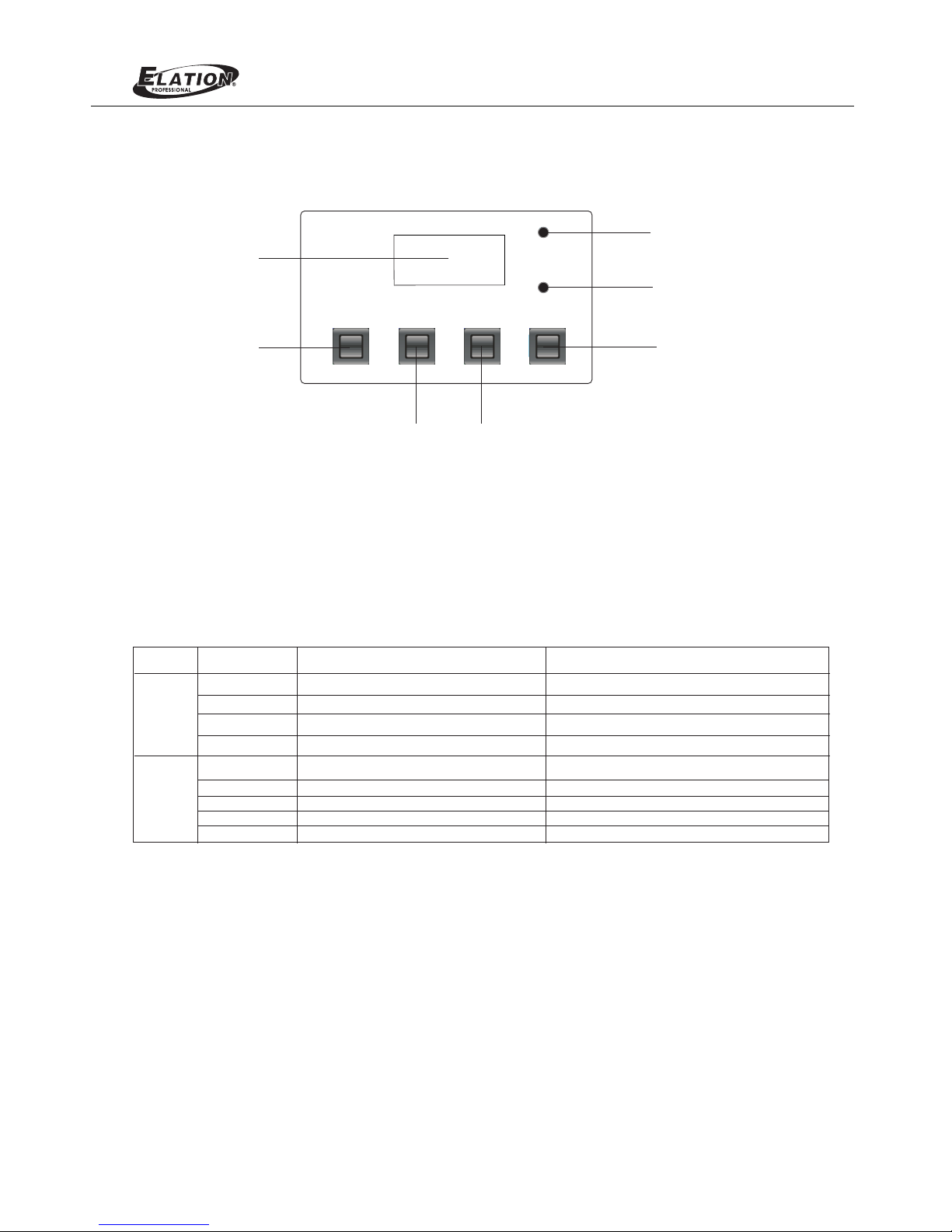
LCD Display
Mode Key
Menu Key Up Key
Power indicator
RDM/DMX indicator
Down Key
LCD DISPLAY/MENU SYSTEM
OPERATION MODES
The “ ” has two different operation modes. It can be used as a 07, 08, 10, 14, 16, 22 channel DMX Lumina Matrix LED
dimmer. Tap “Mode” button to switch the operation mode between “DMX Control Mode” and “Built-in Program Mode”.
Please follow illustrations below to operate the unit in your desired mode.
Mode
Param eter Parameter Va lue
Funct ion
DMX
Pro gram
Addres s
Channe l
No DMX
Glide
Progra m
Speed
Master
Lamp Mod e
Fade Time
001-51 2
07/08/ 10/ 14/ 16/ 22
OFF/Ho ld/ Pro gra m
OFF/ON
01--48 /AU TO
01-100
00-100
Tun gst en/LED
00-100
To set the ini tia l DMX r ece iving add res s
To set the DMX C ont rol M ode
To set the sta tus o f the f ixture when no D MX si gna l input
To set the out put o f the D MX Da ta
To select a bu ilt -in p rog ram
To set the spe ed le vel o f the b uilt-in P rog ram
To set the int ens ity
To set the mod e of La mp
To set the spe ed of t he Fa det ime
Page 8
Lumina Matrix LED
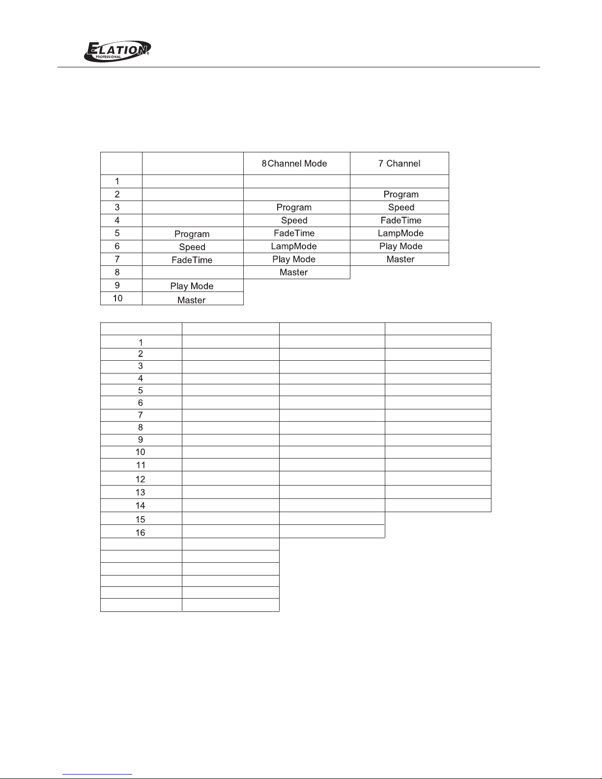
Use this operation mode only when you are about to use the unit as a DMX dimmer. This function can allow
you set your unit dimmer function as a 07, 08, 10,14, 16 or 22 channel DMX dimmer and DMX address.
DMX Mode
DMX Channel Fun ctions Detail s
10 Channe l Mode
DMX
Channel
LED 1-LED 4 Dimme r
LED 1-LED 8 Dimme r LED 1-LED16 Dimm er
LED 9-LED 16 Dimm er
LED 5-LED 8 Dimme r
LED 9-LED 12 Dimm er
LED 13-LE D16 Dim mer
Lamp Mode
DMX Chann el 22 Channe l Mode
LED1 Dimm er LED1 Dimm er LED1-LE D2 Dimm er
LED3-LE D4 Dimm er
LED13-L ED14 Di mmer
LED11- LED12 D immer
LED9-LE D10 Dim mer
LED7-LE D8 Dimm er
LED5-LE D6 Dimm er
LED15-L ED16 Di mmer
Program
Speed
Play Mode
Lamp Mode
Fade Time
Master
LED15 Dim mer LED15 Dim mer
LED14 Dim mer LED14 Dim mer
LED13 Dim mer LED13 Dim mer
LED12 Dim mer LED12 Dim mer
LED11 Di mmer LED11 Di mmer
LED10 Dim mer LED10 Dim mer
LED9 Dimm er LED9 Dimm er
LED8 Dimm er LED8 Dimm er
LED7 Dimm er LED7 Dimm er
LED6 Dimm er LED6 Dimm er
LED5 Dimm er LED5 Dimm er
LED4 Dimm er LED4 Dimm er
LED3Dim mer LED3Dim mer
LED2 Dimm er LED2 Dimm er
LED16 Dim mer LED16 Dim mer
16 Channe l Mode 14 Channe l Mode
Program
Master
Play Mode
Lamp Mode
Fade Time
Speed
17
18
19
20
21
22
Page 9
Lumina Matrix LED
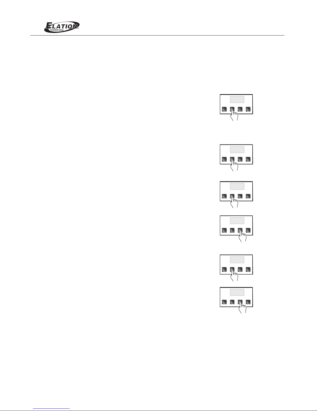
2. Chase Speed Menu:
3. Master (Intensity) Menu:
Use the "UP" and "DOWN " buttons to adjust the light output
intensity between 000 ~ 100. A set value of 000 will give you
the weakest output intensity and a set value of 100 will give
you the full intensity.
Speed
001
MODE MENU UP DOWN
Speed
100
MODE MENU UP DOWN
Dimmer
100
MODE MENU UP DOWN
Dimmer
001
MODE MENU UP DOWN
Press “MENU’ button to select and activate “Chase Speed”
menu. In this menu, you can adjust the program chase speed.
Use the "UP " and "DOWN" buttons to adjust the chase speed
from 001 thru 100. A set value of 100 will give you the fastest
chase speed(approx.1/10th of a second) . While a set value of
001 will give you the slowest chase speed (once every 30 second.).
To adjust the output intensity, you must activate the
Chase Dimmer Menu as the previous step. Press “MENU”
button and select “Chase Dimmer” menu, the LCD will display
“Dimmer” followed by three digits.
Selecting any program of Program01-48 will activate the selected
program; while selecting “Auto” will automatically play the built-in 48
chase programs.
Auto
MODE MENU UP DOWN
Program
01
MODE MENU UP DOWN
Program Mode:
The unit has 48 built-in programs except for Auto. Of course, you can select any of these programs to chase for
a the speed at which the set programs will be chased. more dramatic lighting show, and you can also control
1. Setting your desired Chase Program:
Once you have activated the Chase Mode, you can tap the “MENU”
button to select and activate “Chase Program” menu. The chase pattern
is displayed in the LCD by "Program " followed by two digits 01~48 or
only "AUTO" appears. You can tap “UP” and “DOWN” button
to select any of them to run at a single time.
Page 10

Lumina Matrix LED
2. Selecting the DMX Channel
1. Selecting DMX Address
Press “MENU” button and select DMX channel address menu after having
activated the Receive Mode. The DMX Address Mode is indicated by
"Address” followed by three digits 001~ 512. You can tap the “UP” and
“DOWN” buttons to change the DMX Address Value.
Note: There is no DMX input in the master unit of the connection.
Address
001
Channel
01
MODE MENU UP DOWN
MODE MENU UP DOWN
Press “MENU” button and select Channel Mode. The Channel Mode is
indicated by "Channel" followed by two digits 07,08, 10, 14, 16, 22. You can
tap the "UP” and "DOWN" buttons to change the setting from 07, 08, 10,14
16 or 22 which you wish to run.
Channel Parameter details:
Functions
LED Dimmer DMX value
0---100% equal to intensity
0---100%
Program
DMX 0 --3 for local DMX Dimmer Mode
DMX 4 --7 Program 1
DMX 8 --11 Program2
DMX 12 --15 Program3
DMX 16 -- 19 Program4
…
DMX 192 --195 Program48
DMX 196 --255 Auto
Speed
The bigger DMX value is, the faster the Programe runs
FadeTime DMX value
0
---
100% equals to FadeTime 0---100%
LampMode
DMX 0--127
for choosing the work mode of the LED
DMX 128--255 for choosing Tungsten
Play Mode
DMX 0--80 to stop the Program
DMX 81--160 to pause the Program
DMX 161--255
to play the Program
Master
DMX value
0
---
100% 100%
equals to
Program intensity
0
---
Parameters
4. Lamp Mode Menu:
5. Fade Time Menu:
LampMode
LED
MODE MENU UP DOWN
FadeTime
000
MODE MENU UP DOWN
Press “MENU” button and select “Lamp Mode” menu, the LCD will
display “LampMode Tungdten”, user can press “UP” or “DOWN” button
to switch to “LampMode LED” menu.
Press “MENU” button and select “Fade Time” menu, the LCD will
display “FadeTime” followed by three digits, user can press “UP”
or “DOWN” button set the desired Fade time value from 000 to 100.
Page 11

Lumina Matrix LED
Lumina Matrix LED RDM Parameter IDs
The following tables outline and describe all the RDM parameters IDs associated with Lumina Matrix LED.
Table 1: Lumina Matrix LED RDM Parameter IDs
NOTE:
1. When CH:07 is displayed, overall channels will be controlled by DMX channel 1, and the DMX2~7 will control
to run a 1~48 sequential program.
2. When CH:08 is displayed, channel 1~8 will be controlled by DMX channel 1, channel 9~16 will be controlled by
DMX channel 2. The DMX channel 3~8 will control to run a 1~48 sequential program.
3. When CH:10 is displayed, channel 1~4 will be controlled by DMX channel 1, channel 5~8 will be controlled by
DMX channel 2, the rest will be deduced by analogy... and channel 13~16 will be controlled by DMX channel
4. The DMX channel 5~10 will control to run a 1~48 sequential program.
4. When CH:14 is displayed, channel 1~2 will be controlled by DMX channel 1, channel 3~4 will be controlled
by DMX channel 2, channel 5~6 will be controlled by DMX channel 3, the rest can be deduced by analogy
... and channel 15~16 will be controlled by DMX channel 8. The DMX channel 9~14 will control to run a 1~48
sequential program.
5. When CH:16 is displayed, each channel will be controlled by one DMX channel. This is the factory default
setting.
6. When CH:22 is displayed, DMX channel1~16 will control the LED, and the DMX channel 17~22 will control
to run a 1~48 sequential program.
Page 12

Lumina Matrix LED
Table 1: Lumina Matrix LED RDM Parameter IDs
Page 13

Lumina Matrix LED
Table 2: Lumina Matrix LED Manufacturer Status IDs
Table 3: Lumina Matrix LED Manufacturer Specific PIDs
Manufact urer Defined Status IDs
Manufac turer Spe cific mes sages are i n the range o f 0x8000 —0 xFFDF. Each Manufacturer-sp ecific
Status ID s hall have a u nique mea ning, whi ch shall be c onsiste nt across a ll produc ts having a g iven
Manufac turer ID. S ee Table B- 2, ANSI E1.2 0-2010
Status Me ssage ID
Value Data Value 1 D ata Value 2
Status ID D escript ion
8100H 00H 00H ALL OK
Manufacturer Speci fic PIDs
Manuf act urer Defin d PID s ran ge is 0x8000 -0x ffd f. Se e Table A- 3, ANSI E1.20 -20 10
Get
Allow ed
SET
Allow ed
RDM Par ame ter
ID’s
TYPE UNIT PR EFIX MIN MAX DEFAULT D ESCRIPTI ON
Progr am
Speed
Maste r
Lamp mo de
FadeTi me
Glide
No DMX
8A08H
8A09H
8A01H
8A42H
8A0BH
8A0CH
8A0DH
U8
U8
U8
U8
U8
U8
U8
1
00 48
1
80
1
100
1
1
1
100
0
1
0
0
1
1
1000 100
1
1
00100
2
1
NONE
NONE
NONE
NONE
NONE
NONE
NONE
NONE
NONE
NONE
NONE
NONE
NONE
NONE
LENGT H
Table 1: Lumina Matrix LED RDM Parameter IDs
Page 14

Lumina Matrix LED
Light Source Warm White LED Array
Beam Angle 15 Degrees
Color Temperature 2700K
Power Thru/Input
Light Output
Power Consumption 150W Max.
TECHNICAL SPECIFICATIONS
Please note: Specifications and improvements in the design of this product and this manual are subject to
change without any prior notice.
Weight 9.8Kg
Dimension 400(L)*460(W)*90(H)mm.
Fuse T3.15A 250V 5x20mm
IP Rating IP20
> 4,500 lm
AC100~240V, 50/60Hz
Page 15

MODE MENU DISPLAY
Address 001 - 512
7 / 8 / 10 / 14 / 16 / 22 (8bit)
8 / 10 / 14 / 22 / 38 (16bit)
No DMX OFF/Hold/Program
Dim Mode Standard/Stage/TV/Archi/Theatre
Program 01-48 / Auto
Speed 0 - 100
Fade 0 - 100
Master 0 - 100
Master 0 - 100
LED 1-16 0 - 100
All 0 -100
DMX
Program
Manual
Channel
Page 16

MENU MAP
Dim Mode
001--512
7/8Bit
8/8Bit
10/16Bit
Standard
DMX
Address
Channel
No DMX
10/8Bit
14/8Bit
16/8Bit
22/8Bit
8/16Bit
14/16Bit
OFF/Hold/Program
16/16Bit
22/16Bit
38/16Bit
Stage
TV
Architectural
PROGRAM Program 01--48/Auto
Theatre
Speed 01---100
FadeTime 00-100
Master
00-100
MANUAL
Master
00-100
00-100
00-100
00-100
00-100
00-100
LED1
LED2
LED3
LED4
LED5
LED9
00-100
LED10
00-100
LED6 00-100
LED7 00-100
LED8 00-100
LED11
00-100
LED12 00-100
LED13 00-100
ALL 00-100
LED14 00-100
LED15
00-100
LED16
00-100
Page 17

DMX MAP
Program FadeTime
Dim Mode
8/8Bit
LED 1&8
LED 9&16
Master (16bit)
Master (16bit Fine)
Program
Program Speed
Program FadeTime
7/8Bit
LED 1&16
Master (16bit)
Master (16bit Fine)
Program
Program Speed
LED 10
22/8bit
LED 1
Dim Mode
14/8Bit
LED 1&2
LED 3&4
LED 5&6
LED 7&8
LED 9&10
LED 11&12
LED 13&14
LED 15&16
Program Speed
Program FadeTime
Dim Mode
Master (16bit)
Master (16bit Fine)
LED 11
LED 12
Program
16/8Bit
LED 1
LED 2
LED 3
LED 4
LED 5
LED 6
LED 7
LED 8
LED 9
LED 10
LED 5
LED 6
LED 7
LED 8
LED 9
8/16Bit
LED1&16(16bit)
LED1&16(16bit Fine)
Master (16bit)
Master (16bit Fine)
Program
LED 2
LED 3
LED 4
LED9&10(16bit Fine)
38/16Bit
LED1(16bit)
LED1(16bit Fine)
LED2(16bit)
LED2(16bit Fine)
10/16Bit
LED1&8(16bit)
LED1&8(16bit Fine)
LED9&16(16bit)
LED9&16(16bit Fine)
Master (16bit)
Master (16bit Fine)
Program
Program Speed
Program FadeTime
Dim Mode
6
7
8
9
10
LED9(16bit Fine)
LED11&12(16bit)
LED11&12(16bit Fine)
22/16Bit
LED1&2(16bit)
LED1&2(16bit Fine)
LED3&4(16bit)
LED3&4(16bit Fine)
LED4(16bit)
LED4(16bit Fine)
LED5(16bit)
LED5(16bit Fine)
LED6(16bit)
LED6(16bit Fine)
LED5&6(16bit)
LED5&6(16bit Fine)
LED7&8(16bit)
LED7&8(16bit Fine)
LED9&10(16bit)
4
5
LED3(16bit Fine)
DMX Channel
1
2
3
23
24
LED7(16bit)
LED7(16bit Fine)
LED8(16bit)
LED8(16bit Fine)
LED9(16bit)
LED3(16bit)
17
18
19
11
12
13
14
15
16
25 LED13(16bit)
LED13(16bit Fine)
LED10(16bit)
LED10(16bit Fine)
LED11(16bit)
LED11(16bit Fine)
LED12(16bit)
LED12(16bit Fine)
26
20
21
22
Program Speed
Program FadeTime
Dim Mode
Master (16bit)
Master (16bit Fine)
Program
Program Speed
Program FadeTime
Dim Mode
LED 13
LED 14
LED 15
LED 16
LED 11
LED 12
LED 13
LED 14
LED 15
LED 16
LED13&14(16bit)
LED13&14(16bit Fine)
LED15&16(16bit)
LED15&16(16bit Fine)
Program
Program Speed
Program FadeTime
Dim Mode
Master (16bit)
Master (16bit Fine)
Program
Program Speed
Program FadeTime
Dim Mode
LED14(16bit)
LED14(16bit Fine)
LED15(16bit)
LED15(16bit Fine)
LED16(16bit)
LED16(16bit Fine)
Master (16bit)
Master (16bit Fine)
Program
Program Speed
Program FadeTime
Dim Mode
28
29
30
31
32
33
34
35
36
37
27
38
10/8Bit
LED 1&4
LED 5&8
LED 9&12
LED 13&16
Master (16bit)
Master (16bit Fine)
Program
Program Speed
Program FadeTime
Dim Mode
14/16Bit
LED1&4(16bit)
LED1&4(16bit Fine)
LED5&8(16bit)
LED5&8(16bit Fine)
LED9&12(16bit)
LED9&12(16bit Fine)
LED13&16(16bit)
LED13&16(16bit Fine)
Master (16bit)
Master (16bit Fine)
Page 18

CH1 CH2 CH3 CH4 CH5 CH6
LED 1-16
Master
Dimmer
Master Dim
Fine
Programs Program Speed Program Fade
16-bit Standard (dr 1) 0-20
0-255 0-255 0-255 0-255 0-255 0-255 Stage (dr 2)
21-40
(dim→ (dim→ (dim→ (Slow→ Less→ TV (dr 3)
41-60
bright) bright) bright) Fast) More)
Architectural
(dr 4)
61-80
Theatre (dr 5)
81-100
101-255
CH7
Dim Mode
Default to Unit
Setting
7 Channel Configuration (8 Bit)
Page 19

CH1 CH2 CH3 CH4 CH5 CH6 CH7
LED 1-8 LED 9-16
Master
Dimmer
Master Dim
Fine
Programs Program Speed Program Fade
16-bit Standard (dr 1) 0-20
0-255 0-255 0-255 0-255 0-255 0-255 0-255 Stage (dr 2)
21-40
(dim→ (dim→ (dim→ (dim→ (Slow→ Less→ TV (dr 3)
41-60
bright) bright) bright) bright) Fast) More)
Architectural
(dr 4)
61-80
Theatre (dr 5)
81-100
101-255
8 Channel Configuration (8 Bit)
Dim Mode
Default to Unit
Setting
CH8
Page 20

CH1 CH2 CH3 CH4 CH5 CH6 CH7 CH8 CH9
LED 1-4 LED 5-8 LED 9-12 LED 13-16
Master
Dimmer
Master Dim
Fine
Programs
Program
Speed
Program
Fade
16-bit
Standard (dr
1)
0-20
0-255 0-255 0-255 0-255 0-255 0-255 0-255 0-255 0-255 Stage (dr 2)
21-40
(dim→ (dim→ (dim→ (dim→ (dim→ (dim→ (Slow→ Less→ TV (dr 3)
41-60
bright) bright) bright) bright) bright) bright) Fast) More)
Architectural
(dr 4)
61-80
Theatre (dr
5)
81-100
101-255
10 Channel Configuration (8 Bit)
CH10
Dim Mode
Default to
Unit Setting
Page 21

CH1 CH2 CH3 CH4 CH5 CH6 CH7 CH8 CH9 CH10 CH11 CH12 CH13
LED 1-2 LED 3-4 LED 5-6 LED 7-8 LED 9-10 LED 11-12 LED 13-14 LED 15-16
Master
Dimmer
Master Dim
Fine
Programs
Program
Speed
Program
Fade
16-bit
Standard (dr
1)
0-20
0-255 0-255 0-255 0-255 0-255 0-255 0-255 0-255 0-255 0-255 0-255 0-255 0-255 Stage (dr 2)
21-40
(dim→ (dim→ (dim→ (dim→ (dim→ (dim→ (dim→ (dim→ (dim→ (dim→ (Slow→ Less→ TV (dr 3)
41-60
bright) bright) bright) bright) bright) bright) bright) bright) bright) bright) Fast) More)
Architectural
(dr 4)
61-80
Theatre (dr
5)
81-100
101-255
14 Channel Configuration (8 Bit)
CH14
Dim Mode
Default to
Unit Setting
Page 22

CH1 CH2 CH3 CH4 CH5 CH6 CH7 CH8 CH9 CH10 CH11 CH12 CH13 CH14 CH15 CH16
LED1 LED2 LED3 LED4 LED5 LED6 LED7 LED8 LED9 LED10 LED11 LED12 LED13 LED14 LED15 LED16
0-255 0-255 0-255 0-255 0-255 0-255 0-255 0-255 0-255 0-255 0-255 0-255 0-255 0-255 0-255 0-255
(dim→ (dim→ (dim→ (dim→ (dim→ (dim→ (dim→ (dim→ (dim→ (dim→ (dim→ (dim→ (dim→ (dim→ (dim→ (dim→
bright) bright) bright) bright) bright) bright) bright) bright) bright) bright) bright) bright) bright) bright) bright) bright)
16 Channel Configuration (8 Bit)
Page 23

CH1 CH2 CH3 CH4 CH5 CH6 CH7 CH8 CH9 CH10 CH11 CH12 CH13 CH14 CH15 CH16
LED1 LED2 LED3 LED4 LED5 LED6 LED7 LED8 LED9 LED10 LED11 LED12 LED13 LED14 LED15 LED16
0-255 0-255 0-255 0-255 0-255 0-255 0-255 0-255 0-255 0-255 0-255 0-255 0-255 0-255 0-255 0-255
(dim→ (dim→ (dim→ (dim→ (dim→ (dim→ (dim→ (dim→ (dim→ (dim→ (dim→ (dim→ (dim→ (dim→ (dim→ (dim→
bright) bright) bright) bright) bright) bright) bright) bright) bright) bright) bright) bright) bright) bright) bright) bright)
CH17 CH18 CH19 CH20 CH21
Master
Dimmer
Master Dim
Fine
Programs Program Speed Program Fade
16-bit Standard (dr 1) 0-20
0-255 0-255 0-255 0-255 0-255 Stage (dr 2)
21-40
(dim→ (dim→ (Slow→ Less→ TV (dr 3)
41-60
bright) bright) Fast) More)
Architectural
(dr 4)
61-80
Theatre (dr 5)
81-100
101-255
Dim Mode
Default to Unit
Setting
22 Channel Configuration (8 Bit)
CH22
Page 24

CH1 CH2 CH3 CH4 CH5 CH6 CH7
LED 1&16
(16bit)
LED 1&16
(16bit Fine)
Master
Dimmer
Master Dim
Fine
Programs
Program
Speed
Program
Fade
16-bit
Standard (dr
1)
0-20
0-255 0-255 0-255 0-255 0-255 0-255 0-255 Stage (dr 2)
21-40
(dim→ (dim→ (dim→ (dim→ (Slow→ Less→ TV (dr 3)
41-60
bright) bright) bright) bright) Fast) More)
Architectural
(dr 4)
61-80
Theatre (dr
5)
81-100
101-255
8 Channel Configuration (16 Bit)
CH8
Dim Mode
Default to
Unit Setting
Page 25

CH1 CH2 CH3 CH4 CH5 CH6 CH7 CH8 CH9
LED1&8
(16bit)
LED1&8
(16bit Fine)
LED9&16
(16bit)
LED9&16
(16bit Fine)
Master
Dimmer
Master Dim
Fine
Programs
Program
Speed
Program
Fade
16-bit
Standard (dr
1)
0-20
0-255 0-255 0-255 0-255 0-255 0-255 0-255 0-255 0-255 Stage (dr 2)
21-40
(dim→ (dim→ (dim→ (dim→ (dim→ (dim→ (Slow→ Less→ TV (dr 3)
41-60
bright) bright) bright) bright) bright) bright) Fast) More)
Architectural
(dr 4)
61-80
Theatre (dr
5)
81-100
101-255
10 Channel Configuration (16 Bit)
CH10
Dim Mode
Default to
Unit Setting
Page 26

CH1 CH2 CH3 CH4 CH5 CH6 CH7 CH8 CH9 CH10 CH11 CH12 CH13
LED1&4
(16bit)
LED1&4
(16bit Fine)
LED5&8
(16bit)
LED5&8
(16bit Fine)
LED9&12
(16bit)
LED9&12
(16bit Fine)
LED13&16
(16bit)
LED13&16
(16bit Fine)
Master
Dimmer
Master Dim
Fine
Programs
Program
Speed
Program
Fade
16-bit
Standard (dr
1)
0-20
0-255 0-255 0-255 0-255 0-255 0-255 0-255 0-255 0-255 0-255 0-255 0-255 0-255 Stage (dr 2)
21-40
(dim→ (dim→ (dim→ (dim→ (dim→ (dim→ (dim→ (dim→ (dim→ (dim→ (Slow→ Less→ TV (dr 3)
41-60
bright) bright) bright) bright) bright) bright) bright) bright) bright) bright) Fast) More)
Architectural
(dr 4)
61-80
Theatre (dr
5)
81-100
101-255
14 Channel Configuration (16 Bit)
CH14
Dim Mode
Default to
Unit Setting
Page 27

CH1 CH2 CH3 CH4 CH5 CH6 CH7 CH8 CH9 CH10 CH11 CH12 CH13 CH14 CH15 CH16
LED1&2
(16bit)
LED1&2
(16bit Fine)
LED3&4
(16bit)
LED3&4
(16bit Fine)
LED5&6
(16bit)
LED5&6
(16bit Fine)
LED7&8
(16bit)
LED7&8
(16bit Fine)
LED9&10
(16bit)
LED9&10
(16bit Fine)
LED11&12
(16bit)
LED11&12
(16bit Fine)
LED13&14
(16bit)
LED13&14
(16bit Fine)
LED15&16
(16bit)
LED15&16
(16bit Fine)
0-255 0-255 0-255 0-255 0-255 0-255 0-255 0-255 0-255 0-255 0-255 0-255 0-255 0-255 0-255 0-255
(dim→ (dim→ (dim→ (dim→ (dim→ (dim→ (dim→ (dim→ (dim→ (dim→ (dim→ (dim→ (dim→ (dim→ (dim→ (dim→
bright) bright) bright) bright) bright) bright) bright) bright) bright) bright) bright) bright) bright) bright) bright) bright)
CH17 CH18 CH19 CH20 CH21
Master
Dimmer
Master Dim
Fine
Programs
Program
Speed
Program
Fade
16-bit
Standard (dr
1)
0-20
0-255 0-255 0-255 0-255 0-255 Stage (dr 2)
21-40
(dim→ (dim→ (Slow→ Less→ TV (dr 3)
41-60
bright) bright) Fast) More)
Architectural
(dr 4)
61-80
Theatre (dr
5)
81-100
101-255
22 Channel Configuration (16 Bit)
CH22
Dim Mode
Default to
Unit Setting
Page 28

CH1 CH2 CH3 CH4 CH5 CH6 CH7 CH8 CH9 CH10 CH11 CH12 CH13 CH14 CH15 CH16
LED1
(16bit)
LED1 (16bit
Fine)
LED2
(16bit)
LED2 (16bit
Fine)
LED3
(16bit)
LED3 (16bit
Fine)
LED4
(16bit)
LED4 (16bit
Fine)
LED5
(16bit)
LED5 (16bit
Fine)
LED6
(16bit)
LED6 (16bit
Fine)
LED7
(16bit)
LED7 (16bit
Fine)
LED8
(16bit)
LED8 (16bit
Fine)
0-255 0-255 0-255 0-255 0-255 0-255 0-255 0-255 0-255 0-255 0-255 0-255 0-255 0-255 0-255 0-255
(dim→ (dim→ (dim→ (dim→ (dim→ (dim→ (dim→ (dim→ (dim→ (dim→ (dim→ (dim→ (dim→ (dim→ (dim→ (dim→
bright) bright) bright) bright) bright) bright) bright) bright) bright) bright) bright) bright) bright) bright) bright) bright)
CH17 CH18 CH19 CH20 CH21 CH22 CH23 CH24 CH25 CH26 CH27 CH28 CH29 CH30 CH31 CH32
LED9
(16bit)
LED9 (16bit
Fine)
LED10
(16bit)
LED10
(16bit Fine)
LED11
(16bit)
LED11
(16bit Fine)
LED12
(16bit)
LED12
(16bit Fine)
LED13
(16bit)
LED13
(16bit Fine)
LED14
(16bit)
LED14
(16bit Fine)
LED15
(16bit)
LED15
(16bit Fine)
LED16
(16bit)
LED16
(16bit Fine)
0-255 0-255 0-255 0-255 0-255 0-255 0-255 0-255 0-255 0-255 0-255 0-255 0-255 0-255 0-255 0-255
(dim→ (dim→ (dim→ (dim→ (dim→ (dim→ (dim→ (dim→ (dim→ (dim→ (dim→ (dim→ (dim→ (dim→ (dim→ (dim→
bright) bright) bright) bright) bright) bright) bright) bright) bright) bright) bright) bright) bright) bright) bright) bright)
CH33 CH34 CH35 CH36 CH37
Master
Dimmer
Master Dim
Fine
Programs
Program
Speed
Program
Fade
16-bit
Standard (dr
1)
0-20
0-255 0-255 0-255 0-255 0-255 Stage (dr 2)
21-40
(dim→ (dim→ (Slow→ Less→ TV (dr 3)
41-60
bright) bright) Fast) More)
Architectural
(dr 4)
61-80
Theatre (dr
5)
81-100
101-255
38 Channel Configuration (16 Bit)
CH38
Dim Mode
Default to
Unit Setting
Page 29

DIMMER
Standard (default) 0 0 0 0
Stage 780 1100 1540 1660
TV 1180 1520 1860 1940
Architectural 1380 1730 2040 2120
Theatre 1580 1940 2230 2280
DIMMING CURVE MODES
0 sec Fade Time
1 sec Fade Time
100%
50%
10%
0%
Time (ms)
0 Sec
Dimming Curve
Ramp Effect
Rise Time Down Time
255 255
0 0
Rise Time (ms) Down Time (ms) Rise Time (ms) Down Time (ms)
 Loading...