

Page 1
English Deutsch Français
中文
日本語
Important
Please read this User's Manual carefully to familiarize yourself with safe and effective
usage procedures. Please retain this manual for future reference.
Wichtig
Bitte lesen Sie diese Bedienungsanleitung sorgfältig durch, um sich mit dem sicheren
und rationellen Betrieb dieses Produkts vertraut zu machen. Bewahren Sie das
vorliegende Handbuch zu Referenzzwecken auf.
Important
Veuillez lire attentivement ce manuel d’utilisation pour utiliser pleinement votre appareil
en toute sécurité. Veuillez conserver ce manuel pour référence ultérieure.
重要
请仔细阅读用户指南,熟练掌握其安全和有效的操作程序。
请妥善保存此手册,供日后参考。
重要
ご使用前には必ず取扱説明書をよくお読みになり、正しくお使いください。
この取扱説明書は大切に保管してください。
Page 2
For U.S.A. , Canada, etc. (rated 100-120 Vac) Only
FCC Declaration of Conformity
We, the Responsible Party EIZO NANAO TECHNOLOGIES INC.
5710 Warland Drive, Cypress, CA 90630
Phone: (562) 431-5011
declare that the product Trade name: EIZO
Model: RadiForce GS520
is in conformity with Part 15 of the FCC Rules. Operation of this product is subject to the
following two conditions: (1) this device may not cause harmful interference, and (2) this device
must accept any interference received, including interference that may cause undesired
operation.
This equipment has been tested and found to comply with the limits for a Class B digital device,
pursuant to Part 15 of the FCC Rules. These limits are designed to provide reasonable protection
against harmful interference in a residential installation. This equipment generates, uses, and can
radiate radio frequency energy and, if not installed and used in accordance with the instructions, may
cause harmful interference to radio communications. However, there is no guarantee that interference
will not occur in a particular installation. If this equipment does cause harmful interference to radio
or television reception, which can be determined by turning the equipment off and on, the user is
encouraged to try to correct the interference by one or more of the following measures.
* Reorient or relocate the receiving antenna.
* Increase the separation between the equipment and receiver.
* Connect the equipment into an outlet on a circuit different from that to which the receiver is
connected.
* Consult the dealer or an experienced radio/TV technician for help.
Changes or modications not expressly approved by the party responsible for compliance could void
the user’s authority to operate the equipment.
Note
Use the attached specied cable below or EIZO signal cable with this monitor so as to keep
interference within the limits of a Class B digital device.
- AC Cord
- Shielded Signal Cable (Enclosed)
Canadian Notice
This Class B digital apparatus complies with Canadian ICES-003.
Cet appareil numérique de le classe B est comforme à la norme NMB-003 du Canada.
Page 3
It shall be assured that the final system is in compliance to IEC60601-1-1
requirements.
English
Page 4
2
SAFETY SYMBOLS
SAFETY SYMBOLS
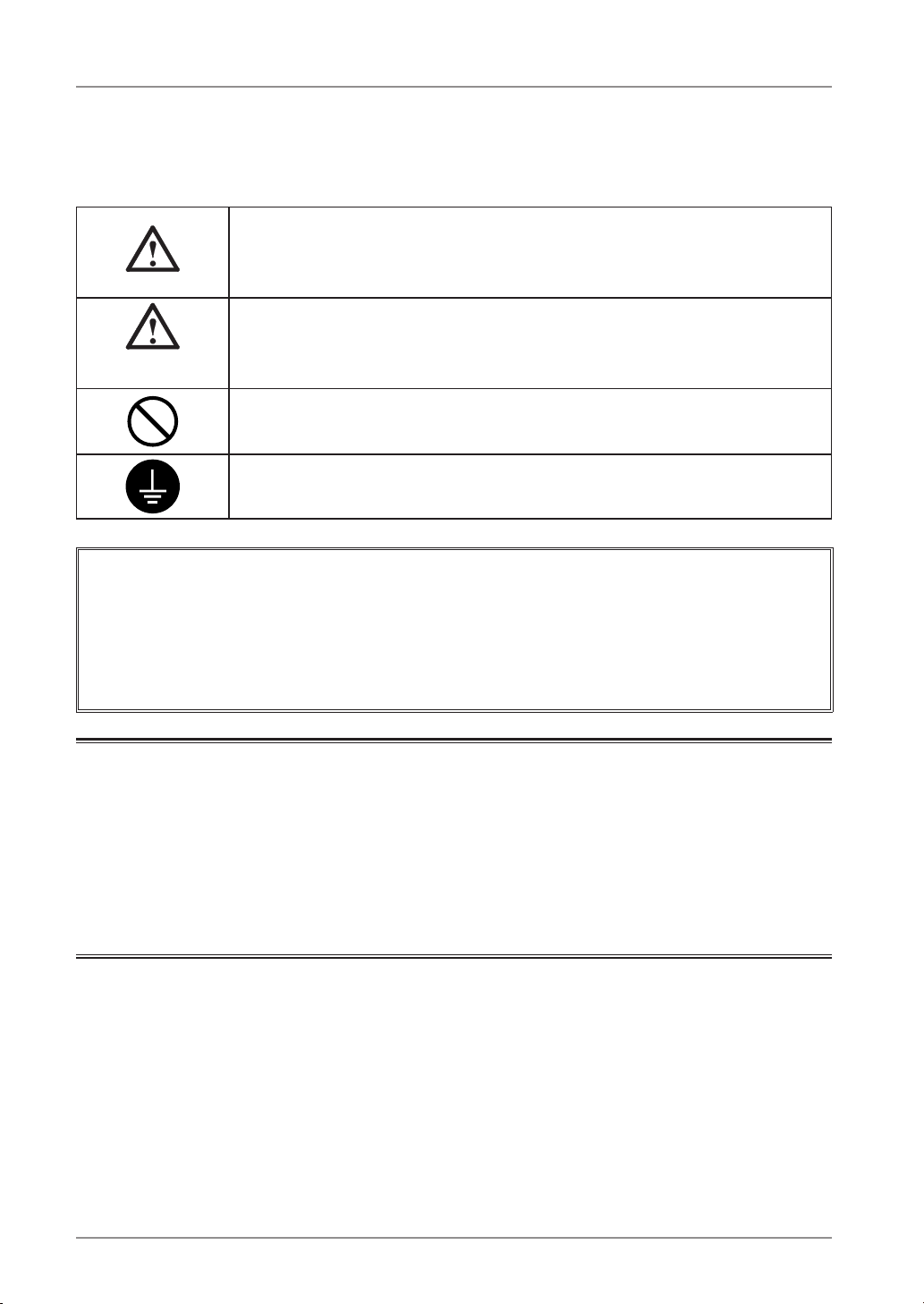
This manual uses the safety symbols below. They denote critical information. Please read them
carefully.
WARNING
Failure to abide by the information in a WARNING may result in serious
injury and can be life threatening.
CAUTION
Failure to abide by the information in a CAUTION may result in moderate
injury and/or propertyor product damage.
Indicates a prohibited action.
Indicates to ground for safety.
• Power supplied equipment can emit electromagnetic waves, that could influence, limit or
result in malfunction of the monitor. Install the equipment in a controlled environment, where
such effects are avoided.
• This is a monitor intended for use in a medical image system.
• Product specifications may vary depending on the region. Confirm the specifications in the
manual written in the language of the region of purchase.
Copyright© 2008 EIZO NANAO CORPORATION All rights reserved. No part of this manual
may be reproduced, stored in a retrieval system, or transmitted, in any form or by any means,
electronic, mechanical, or otherwise, without the prior written permission of EIZO NANAO
CORPORATION.
EIZO NANAO CORPORATION is under no obligation to hold any submitted material or
information confidential unless prior arrangements are made pursuant to EIZO NANAO
CORPORATION's receipt of said information. Although every effort has been made to ensure
that this manual provides up-to-date information, please note that EIZO monitor specifications
are subject to change without notice.
Apple and Macintosh are registered trademarks of Apple Inc.
VGA is a registered trademark of International Business Machines Corporation.
VESA is a registered trademark of Video Electronics Standards Association.
Windows is a registered trademark of Microsoft Corporation.
RealVision is a registered trademark of RealVision Inc.
Matrox is a registered trademark of Matrox Electronic Systems Ltd.
PowerManager, RadiCS and RadiNET are trademarks of EIZO NANAO CORPORATION.
ScreenManager, RadiForce and EIZO are registered trademarks of EIZO NANAO
CORPORATION in Japan and other countries.
Page 5

TABLE OF CONTENTS
3
PRECAUTIONS .................................................................................................................... 4
1. Introduction .............................................................................................................................. 9
1-1. Features ..................................................................................................................................... 9
1-2. Package Contents ...................................................................................................................... 9
1-3. Controls and Connectors ......................................................................................................... 10
2. Installation .............................................................................................................................. 12
2-1. Before Connecting .................................................................................................................... 12
2-2. Cable Connection ..................................................................................................................... 13
2-3. Environmental Settings ........................................................................................................... 16
3. Adjustment and Settings ........................................................................................................ 18
3-1. How to use the ScreenManager ............................................................................................... 18
3-2. ScreenManager menu .............................................................................................................. 19
3-3. CAL Switch Function ................................................................................................................ 23
3-4. Adjustment Lock Function ........................................................................................................ 24
4. Brightness Adjustment and Image Adjustment ...................................................................... 25
4-1. Brightness Adjustment ............................................................................................................. 25
4-2. Image Adjustments .................................................................................................................. 25
5. Making use of USB (Universal Serial Bus) ............................................................................ 26
6. Attaching an Arm ................................................................................................................... 28
7. Troubleshooting ...................................................................................................................... 29
8. Cleaning ................................................................................................................................. 31
9. Specifications ......................................................................................................................... 32
10. Glossary .............................................................................................................................. 35
TABLE OF CONTENTS
English
Page 6
4
PRECAUTIONS
PRECAUTIONS
IMPORTANT!
•
This product has been adjusted specifically for use in the region to which it was originally
shipped.
If operated outside the region to which it was originally shipped, the product may not
perform as stated in the specifications.
•
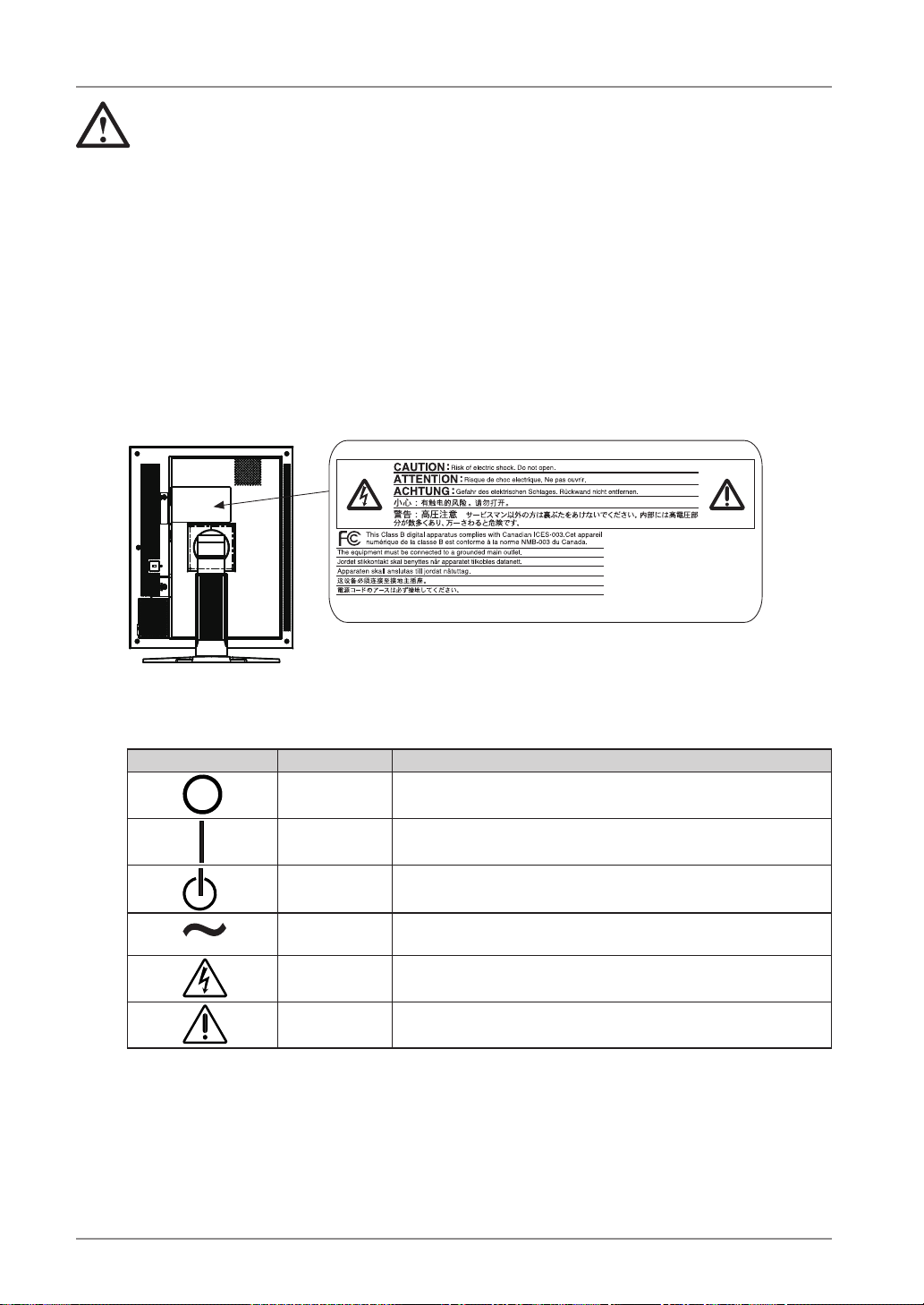
To ensure personal safety and proper maintenance, please read this section and the
caution statements on the unit (refer to the figure below).
[Location of the Caution Statements]
[Symbols on the unit]
Symbol Location This symbol indicates
Rear Main power switch
Press to turn the monitor’s main power off.
Rear Main power switch
Press to turn the monitor’s main power on.
Front
Control Panel
Power switch
Press to turn the monitor’s power on or off.
Rear
Name Plate
Alternating current
Rear Alerting electrical hazard
Rear Caution
Refer to SAFETY SYMBOLS section in this manual.
Page 7
PRECAUTIONS
5
WARNING
If the unit begins to emit smoke, smells like something is burning, or
makes strange noises, disconnect all power connections immediately
and contact your dealer for advice.
Attempting to use a malfunctioning unit may result in fire, electric shock, or
equipment damage.
Do not open the cabinet or modify the unit.
Opening the cabinet or modifying the unit may result in fire, electric shock,
or burn.
Refer all servicing to qualified service personnel.
Do not attempt to service this product yourself as opening or removing
covers may result in fire, electric shock, or equipment damage.
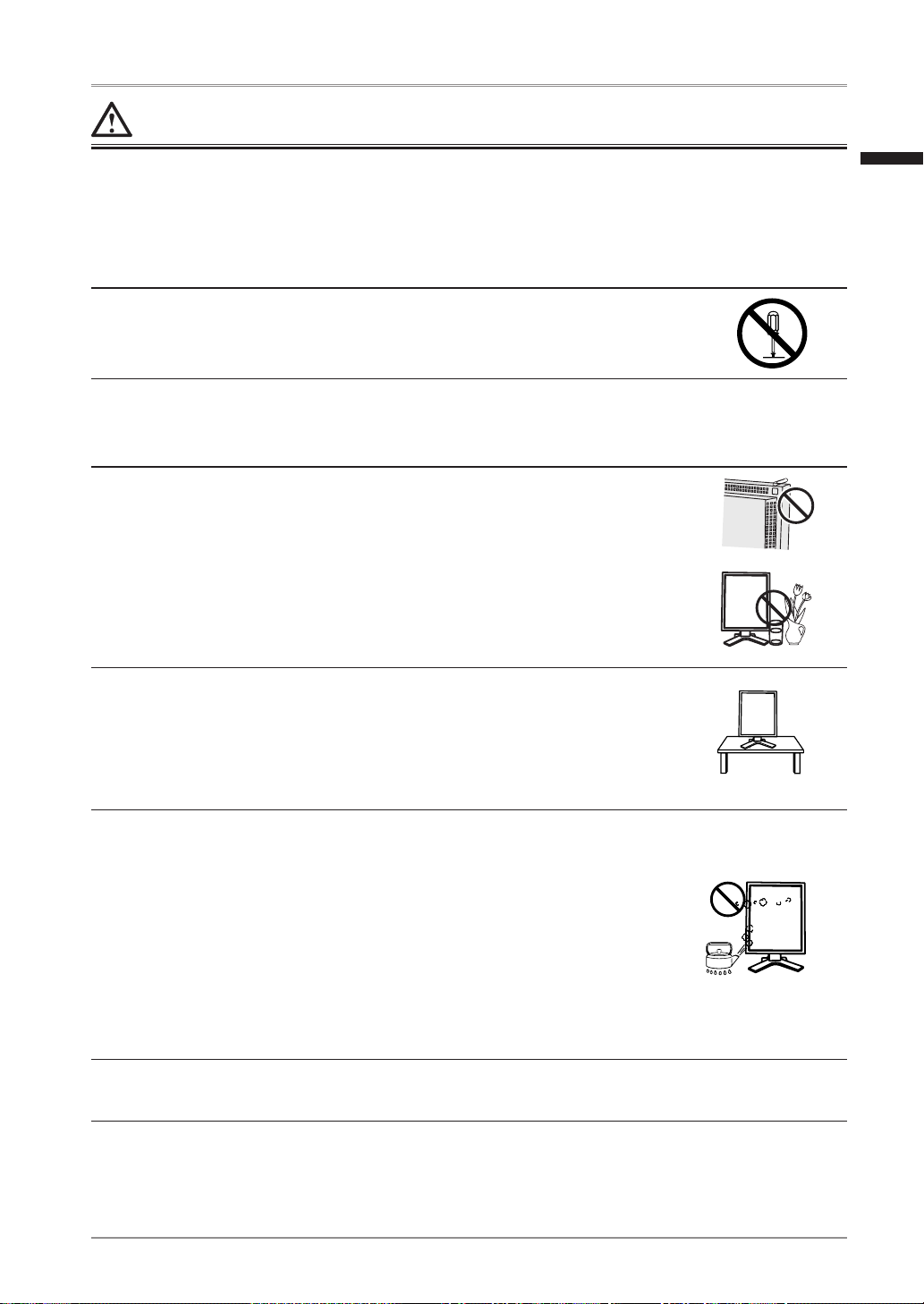
Keep small objects or liquids away from the unit.
Small objects accidentally falling through the ventilation slots into the
cabinet or spillage into the cabinet may result in fire, electric shock, or
equipment damage. If an object or liquid falls/spills into the cabinet, unplug
the unit immediately. Have the unit checked by a qualified service engineer
before using it again.
Place the unit at the strong and stable place.
A unit placed on an inadequate surface may fall and result in injury or
equipment damage. If the unit falls, disconnect the power immediately and
ask your dealer for advice. Do not continue using a damaged unit. Using a
damaged unit may result in fire or electric shock.
OK
Set the unit in an appropriate location.
Not doing so may result in fire, electric shock, or equipment damage.
• Do not place outdoors.
• Do not place in the transportation system (ship, aircraft, trains,
automobiles, etc.)
• Do not place in a dusty or humid environment.
• Do not place in a location where the steam comes directly on the screen.
• Do not place near heat generating devices or a humidifier.
• Do not place in an inflammable gas environment.
To avoid danger of suffocation, keep the plastic packing bags away
from babies and children.
English
Page 8
6
PRECAUTIONS
WARNING
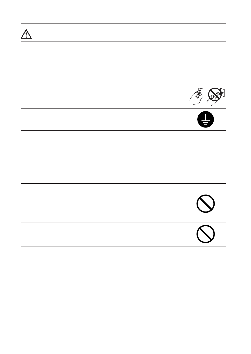
Use the enclosed power cord and connect to the standard power
outlet of your country.
Be sure to remain within the rated voltage of the power cord.
Not doing so may result in fire or electric shock.
Power supply: 100-120/200-240 Vac 50/60Hz
To disconnect the power cord, grasp the plug firmly and pull.
Tugging on the cord may damage and result in fire or electric shock.
OK
The equipment must be connected to a grounded main outlet.
Not doing so may result in fire or electric shock.
Use the correct voltage.
• The unit is designed for use with a specific voltage only. Connection
to another voltage than specified in this Use’s Manual may cause fire,
electric shock, or equipment damage.
Power supply: 100-120/200-240 Vac 50/60Hz
• Do not overload your power circuit, as this may result in fire or electric
shock.
Handle the power cord with care.
• Do not place the cord underneath the unit or other heavy objects.
• Do not pull on or tie the cord.
If the power cord becomes damaged, stop using it. Use of a damaged cord
may result in fire or electric shock
Never touch the plug and power cord if it begins to thunder.
Touching them may result in electric shock.
When attaching an arm stand, please refer to the user's manual of the
arm stand and install the unit securely.
Not doing so may cause the unit to come unattached, which may result in
injury or equipment damage. When the unit is dropped, please ask your
dealer for advice. Do not continue using a damaged unit. Using a damaged
unit may result in fire or electric shock. When reattaching the tilt stand,
please use the same screws and tighten them securely.
Page 9
PRECAUTIONS
7
WARNING
Do not touch a damaged LCD panel directly with bare hands.
The liquid crystal which leaks from the panel is poisonous if it enters the
eyes or mouth.
If any part of the skin or body comes in direct contact with the panel,
please wash thoroughly. If some physical symptoms result, please consult
your doctor.
Lamps contain mercury, dispose according to local, state or federal
laws.
CAUTION
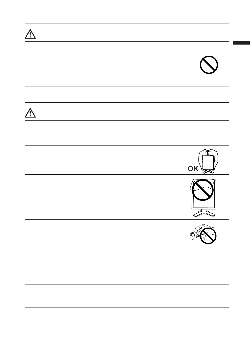
Handle with care when carrying the unit.
Disconnect the power cord and cables when moving the unit. Moving the unit with the cord
attached is dangerous. It may result in injury.
When handling the unit, grip the bottom of the unit firmly with
both hands ensuring the panel faces outward before lifting.
Dropping the unit may result in injury or equipment damage.
Do not block the ventilation slots on the cabinet.
•
Do not place any objects on the ventilation slots.
•
Do not install the unit in a closed space.
•
Do not use the unit laid down or upside down.
Blocking the ventilation slots prevents proper airflow and may result in
fire, electric shock, or equipment damage.
Do not touch the plug with wet hands.
Doing so may result in electrical shock.
Use an easily accessible power outlet.
This will ensure that you can disconnect the power quickly in case of a
problem.
Periodically clean the area around the plug.
Dust, water, or oil on the plug may result in fire.
Unplug the unit before cleaning it.
Cleaning the unit while it is plugged into a power outlet may result in
electric shock.
If you plan to leave the unit unused for an extended period,
disconnect the power cord from the wall socket after turning off
the power switch for the safety and the power conservation.
English
Page 10

8
PRECAUTIONS
Notice for this monitor
The backlight of the LCD panel has a fixed life span. When the screen becomes dark or begins
to flicker, please contact your dealer.
The backlight of the LCD panel has a fixed life span. When the screen becomes dark or begins
to flicker, please contact your dealer.
Do not press on the panel or edge of the frame strongly, as this may result in damage to the
screen. There will be prints left on the screen if the pressed image is dark or black. If pressure
is repeatedly applied to the screen, it may deteriorate or damage your LCD panel. Leave the
screen white or black to decrease the prints.
When the screen image is changed after displaying the same image for extended periods of
time, an afterimage may appear. Use the screen saver or timer to avoid displaying the same
image for extended periods of time.
When the monitor is cold and brought into a room or the room temperature goes up quickly,
dew condensation may occur inside and outside the monitor. In that case, do not turn the
monitor on and wait until dew condensation disappears, otherwise it may cause some damages
to it.
Do not scratch or press on the panel with any sharp objects, such as a pencil or pen as this
may result in damage to the panel. Do not attempt to brush with tissues as this may scratch the
LCD panel.
To use the monitor comfortably
An excessively dark or bright screen may affect your eyes. Adjust the brightness of the monitor
according to the environmental conditions.
Staring at the monitor for a long time tires your eyes. Take a 10-minute rest every hour.
Page 11
1. Introduction
9
1. Introduction
Thank you for choosing an EIZO Monochrome Monitor.
1-1. Features
• DVI (p.35) digital input (TMDS (p.35)) compliant
• Horizontal scan frequency 31 - 135 kHz
• Vertical scan frequency 19.0 - 61.0 Hz
(VGA TEXT: 69 - 71 Hz, QSXGA: 19 - 51 Hz,)
• Frame synchronous mode 49.0 - 51.0 Hz supported
• Resolution 5M pixels (Portrait: 2048 × 2560 dots (H × V))
• CAL Switch function for selecting an optimal calibration mode (p. 23)
• Selectable DICOM (p. 35) Part 14 complied screen
• USB (Universal Serial Bus) hub support (p. 26)
• The quality control software “RadiCS LE“ (for Windows) used to calibrate the
monitor is included (refer to the EIZO LCD Utility Disk).
• The utility software “ScreenManager Pro for Medical“ (for Windows) to control the
monitor from a PC with mouse/keyboard is included (refer to the EIZO LCD Utility
Disk).
• The height adjustable stand incorporated
• Slim bezel
1-2. Package Contents
Please contact your local dealer for assistance if any of the listed items are missing or
damaged.
•
LCD Monitor*
1
•
User’s Manual
•
Power Cord
•
LIMITED WARRANTY
•
Signal Cable (FD-C39)
•
Cleaning Kit “ScreenCleaner”
•
EIZO USB Cable (MD-C93)
(GS520-BLG / GS520-CLG only)
•
EIZO LCD Utility Disk
•
Recycling Information
*1
The landscape position is the default monitor orientation. For the portrait position, rotate the monitor ninety
degrees counter-clockwise before installing it.
Tips
•Please retain the packing materials for future transport of the monitor.
English
Page 12
10
1. Introduction
1-3. Controls and Connectors
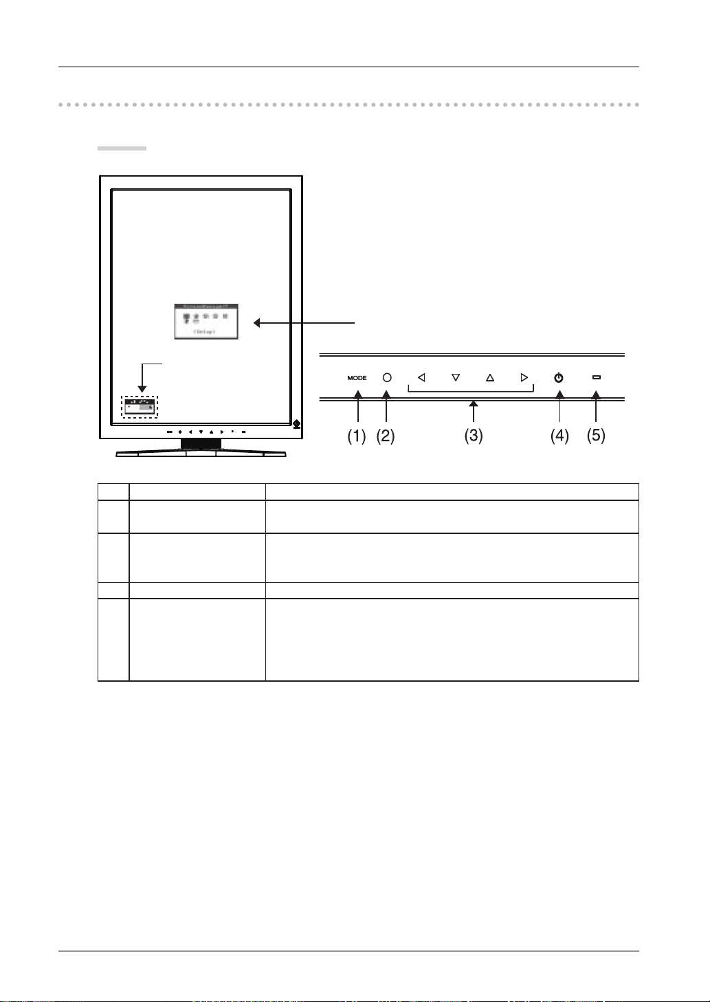
Front
(1) Mode Switch Displays the CAL Switch menu (p. 23).
(2) Enter Switch Displays the Adjustment menu, determines an item on the menu
screen, and saves values adjusted
(3) Directing Switches
*
1
(Left, Down, Up, Right)
Chooses an adjustment item or increases/decreases adjusted
values for advanced adjustments using the Adjustment menu
(p. 18)
(4) Power Switch Turns the power on or off.
(5) Power indicator
*
2
Indicates monitor’s operation status.
Green:
Orange:
Flashing orange slowly:
Off:
Operational
Power saving
Power off (Main power is on)
Main Power off
*1
When the monitor is oriented in the landscape position, these switches can be changed to Up, Left, Right,
and Down (p. 16).
*2
To disable the power indicator while the monitor is operational, see p. 22. For power indicator status when
using the “Off Timer,” see p.22.
ScreenManager
®
main menu
CAL Switch menu
Control Panel
Page 13
1. Introduction
11
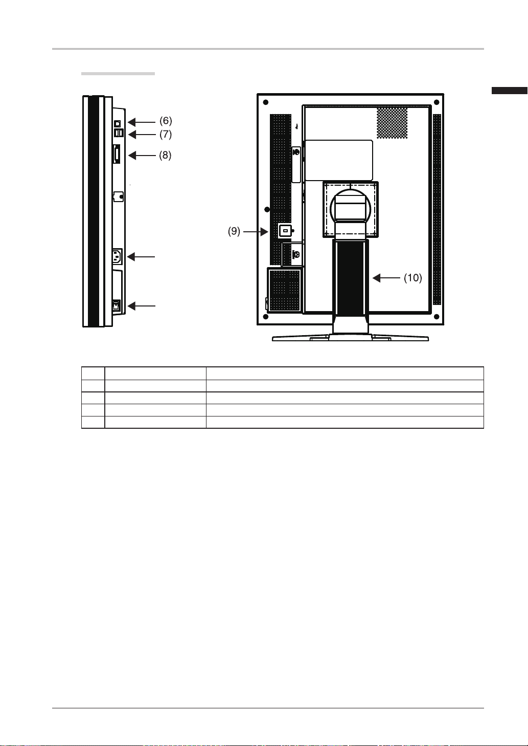
Side / Rear
(6) USB port (Up) Connects the USB cable in order to use the provided software.
(7) USB port (Down) Connects a peripheral USB device.
(8) Input signal connectors DVI-D connector
(9) Security lock slot
*
3
Complies with Kensington’s MicroSaver security system.
(10) Stand
*
4
Used to adjust the height and angle of the monitor screen.
*3
Allows for connection of a security cable.
*4
The LCD monitor can be oriented in the landscape position. (It can rotate clockwise ninety degrees.)
By removing the monitor stand, the LCD monitor can be used with the optional arm stand (p. 28).
Power connector
Main Power Switch
English
Page 14

12
2. Installation
2. Installation
2-1. Before Connecting
Before connecting your monitor to the PC, change the display screen settings resolution
(p. 35) and frequency in accordance with the charts below.
Tips
• When your computer and monitor support VESA DDC, the appropriate resolution and
the refresh rate are set just by plugging your display into the computer without any
manual settings.
Resolution Frequency Dot
Clock
Single Link Dual Link Packed Pixel
Portrait Land-
scape
Portrait Land-
scape
Portrait Land-
scape
720 x 400 VGA TEXT 70 Hz 300
MHz
(Max.)
√ √ √ √ √ √
640 x 480 VGA 60 Hz
√ √ √ √ √ √
800 x 600 VESA 60 Hz
√ √ √ √
1024 x 768 VESA 60 Hz
√ √ √ √
1280 x 1024 VESA 60 Hz
√ √ √ √
1600 x 1200 VESA 60 Hz
√ √ √ √
2048 x 1280 5M Packed Pixel 50 Hz
√
1280 x 2048 5M Packed Pixel 50 Hz
√
2560 x 2048 Dual Link 50 Hz
√
2048 x 2560 Dual Link 50 Hz
√
2560 x 2048 Single Link 25Hz 25 Hz
√
2048 x 2560 Single Link 25Hz 25 Hz
√
2560 x 2048 Single Link 20Hz 20 Hz
√
2048 x 2560 Single Link 20Hz 20 Hz
√
“
√
”
: Supported
Page 15

2. Installation
13
2-2. Cable Connection
NOTE
•Be sure that the power switches of both the PC and the monitor are OFF.
•Refer to the PC user's manual when connecting the monitor.
•Before making a connection for non monochrome signal only specifications, the monitor
must be configured. For more information, refer to “2-3. Environmental Settings”
(p. 16).
1
Rotate the monitor ninety degrees counter-clockwise into the portrait
position.
2
Connect the signal cable to the DVI-D input connector on the rear of
the monitor and to the video output connector on the PC.
After connecting, secure the cable connectors with the attached screw-in fasteners.
Signal Cable Connector on PC PC
Signal cable (FD-C39) Video Output Connector /
DVI-D
Exclusive graphics board
(p. 33)
Signal cable
(FD-C39)
Power cord
English
Page 16

14
2. Installation
3
Connect the power cord to the power connector on the rear of the
monitor.
4
Thread the power cord and signal cable through the cable holder on
the rear of the monitor stand.
NOTE
•When threading the cables through the cable holder, lead them to the cable
entrance side and pinch the projection to open the cable entrance.
•It is recommended that some slack be left in the cables to allow for smooth
adjustment of the monitor stand and easy rotation between the portrait and
landscape positions.
5
Connect the other end of the power cord to a power outlet.
WARNING
Use the enclosed power cord and connect to the standard power
outlet of your country.
Be sure to remain within the rated voltage of the power cord.Not doing so may result in fire or electric shock.
The equipment must be connected to a grounded main outlet.
Not doing so may result in fire or electric shock.
6
Turn on the monitor's power by touching the power switch.
The monitor’s power indicator will light up green.
Projection
Cable entrance
Cable holder
Page 17

2. Installation
15
7
Turn on the PC’s power.
The image will appear.
If an image does not appear, refer to “7. Troubleshooting” (p. 29) for additional
advice.
When finished, turn off the PC and the monitor.
Tips
•Adjust the brightness of the screen depending on the brightness of your
environment.
•Be sure to take adequate rests. A 10-minute rest period each hour is suggested.
8
When using the software “RadiCS LE” (for Windows) or
“ScreenManager Pro for Medical” (for Windows) connect the monitor
to a USB compliant Windows computer (or other USB hub) with a
USB cable.
Refer to “5. Making use of USB (Universal Serial Bus)” (p. 26).
English
Page 18

16
2. Installation
2-3. Environmental Settings
The monitor may need to be set in some environment. If you install it for the first time or
change environment, set the monitor.
• Set the signal corresponding to make a connection for non monochrome signal only
specifications.
• Set the monitor orientation.
If the monitor is in portrait position and make a connection for monochrome signal only
specifications, no setting is required.
NOTE
•Refer to the manual of the graphics board.
•These environment described below can be set regardless of whether or not the computer
is running.
How to set
1
Turn off the monitor power by touching the power switch on the
control panel.
2
Touch the power switch while touching the mode switch on the
control panel.
3
The <Signal Selection> menu appears.
Select (or check) the signal with directing
switches corresponding to the kind of
graphics board or the image data to be
displayed and touch the enter switch.
4
Next the <Orientation> menu appears.
Select (or check) the orientation with
directing switches according to your
monitor orientation and touch the enter
switch.
Mode Switch Power Switch
Signal Selection Menu
Orientation Menu
Page 19

2. Installation
17
Monitor Orientation Display Example
Landscape
Select this option when using the Landscape orientation.
A
A
Portrait (SW)
Select this option when using the Portrait orientation.
Graphics board utility software is used to rotate the
display image 90 degrees.
Portrait (HW)
Select this option when using the Portrait orientation.
The monitor function is used to rotate the display image
90 degrees.
5
Restart the computer if the settings have been changed.
English
Page 20

18
3. Adjustment and Settings
3. Adjustment and Settings
3-1. How to use the ScreenManager
Screen adjustments and settings can be performed with the ScreenManager (OSD) and
buttons of the monitor.
Adjustment Startup Description
ScreenManager menu Enter Switch 3-2. ScreenManager menu (p. 19)
CAL Switch menu Mode Switch 3-3. CAL Switch Function (p. 23)
Switches
*Adjustment Lock Enter Switch + Power Switch 3-4. Adjustment Lock Function (p. 24)
*Signal Selection Orientation
Selection
Mode Switch + Power Switch 2-3. Environmental Settings (p. 16)
For information about each function, refer to each chapter described above.
NOTE
• The ScreenManager menu and the CAL Switch menu cannot be displayed at the same
time.
Mode Switch
Power Switch
Enter Switch
CAL Switch menu
Directing Switches
Left, Down, Up, Right
ScreenManager
menu
Page 21

3. Adjustment and Settings
19
3-2. ScreenManager menu
Using ScreenManager menu controls the screen adjustment and settings. Refer to the
“Explanation” column in the following table for each detailed functions.
Functions
The following table shows all the ScreenManager’s adjustment and setting menus.
Main menu Sub menu Explanation
Setup Mode Preset Mode Preset Function <Setup>-<Mode
Preset>(P. 21)
Mode Brightness 4-1. Brightness Adjustment (p. 25)
Reset
PowerManager DVI DMPM
Power Saving Function <PowerManager> (p. 21)
Others Border Intensity Image Adjustment <Others>(p.25)
Off Timer Turn off the monitor after a specified
time. (p. 22)
Menu Settings Menu Position Adjust the menu position
Menu Off Timer Set the menu displaying time.*
1
Power Indicator Make non-light for Green lighting when
the screen is displayed. (p. 22)
Reset Return to the factory default settings.
(p. 33)
Information Information Review the ScreenManager’s settings,
model name, serial number and usage
time.*
2
Language English, German, French,
Spanish, Italian, Swedish,
Chinese (Simplified),
Chinese (Traditional) and
Japanese
Select the ScreenManager’s language.
*1
The display time of the CAL Switch menu can be adjusted.
*2
Due to factory inspection, the usage time may not be “0 hours” at time of shipping.
English
Page 22

20
3. Adjustment and Settings
How to use the ScreenManager
[Entering the ScreenManager]
Touch the enter switch.
[Making adjustments and settings]
1. Select the desired submenu icon with the directing switches and touch the enter switch.
2. Select the desired setting icon with the directing switches and touch the enter switch.
3. Make any required adjustments with the directing switches and touch the enter switch.
[Exiting the ScreenManager]
1. To return to the main menu, select the <Return> icon or touch the Down directing
switch twice, followed by the enter switch.
2. To exit the ScreenManager, select the <Exit> icon or touch the Down directing switch
twice, followed by the enter switch.
NOTE
•Touching the enter switch twice quickly also exits the ScreenManager.
ScreenManager Menu
Page 23

3. Adjustment and Settings
21
Mode Preset Function <Setup>-<Mode Preset>
When CAL Switch mode is selected, the computer can be forced to display only specified
modes. Use this function when the display modes are restricted or when the display should
not be changed needlessly.
[How to set]
1. Select <Mode Preset> in the ScreenManager <Setup> menu.
2. Set each mode to “On” or “Off”.
NOTE
• You cannot disable all modes. Set one or more modes to “On”.
[How to cancel]
1. Select <Mode Preset> in the ScreenManager <Setup> menu.
2. Set the mode that you wish to display to “On”.
Power Saving Function <PowerManager>
The <PowerManager> menu in the ScreenManager enables to set the power saving.
This monitor complies with the “DVI DMPM” (p. 35).
NOTE
• Do your part to conserve energy, turn off the monitor when you are finished using it.
Disconnecting the monitor from the power supply is recommended to save energy
completely.
• Even if the monitor is in a power saving mode, USB compliant devices function when
they are connected to the monitor’s USB (both the upstream and the downstream ports).
Therefore, power consumption of the monitor will change according to the connected
devices even if the monitor is in a power saving mode.
[How to set]
1. Set the PC’s power saving settings.
2. Select “DVI DMPM” in the <PowerManager> menu.
[Power saving system]
PC Monitor Power Indicator
On Operation Green
Power saving/ Off mode Power saving Orange
[Power Resumpion Procedure]
Operate the mouse or keyboard to return to a normal screen.
English
Page 24

22
3. Adjustment and Settings
Off Timer <Others>-<Off Timer>
The off timer function causes the monitor to turn off automatically after a predetermined
amount of time has lapsed. This function was created to reduce the afterimages particular
to LCD monitors, which appear when the screen is left on for long periods without use.
[How to set]
1. Select <Off Timer> in the ScreenManager <Others> menu.
2. Select “Enable” and touch the Right and Left directing switches to adjust the operating
time (1 to 23 hours).
[Off timer system]
PC Monitor Power Indicator
Operating time (1H - 23H) Operational Green
Last 15 min. in operating time Advance Notice *
1
Flashing green
Operating time expired Power off Flashing orange slowly
*1
By touching the power switch on the control panel during the Advance Notice period, the operating time can
be reset to 90 minutes. Resetting can be performed an unlimited number of times.
[How to restore power]
Touch the power switch to return to a normal screen.
NOTE
• The off timer function works while the PowerManager is active, but there is no advance
notice before the monitor's power is turned off.
Power Indicator Function <Others>-<Power Indicator >
Use the function to keep the power indicator without light while the monitor is operational.
(The power indicator is set by default to light when the power is turned on.)
[How to set]
1. Select <Power Indicator> in the ScreenManager <Others> menu.
2. Select “Disable”.
Page 25

3. Adjustment and Settings
23
3-3. CAL Switch Function
The most suitable display mode is available by switching the mode switch on the control
panel.
The <Brightness> settings can be adjusted on the CAL Switch menu.
CAL Switch Modes
Mode Description
1 - DICOM Used to display images in the DICOM mode (p. 35)
2 - Native Select this option to display images using the native characteristics of
the monitor panel.
3 - CAL Used for monitor calibration
*
All modes can be calibrated independently. The mode name can also be changed using the calibration kit
(p. 34).
How to use the CAL Switch Function
[Entering the CAL Switch menu]
Touch the mode switch.
[Selecting the CAL Switch mode]
Touch the mode switch while the CAL Switch menu is displayed.
Touching the mode switch allows you to select the following mode.
1-DICOM 2-Navive 3-CAL 1-DICOM
[Making brightness adjustments in CAL Switch mode]
1. Touch the mode switch.
2. Adjust the brightness value with the Left and Right directing switches.
[Closing the CAL Switch menu]
Touch the enter switch.
NOTE
• The ScreenManager menu and CAL Switch menu cannot be displayed at the same time.
• When switching between modes, the monitor can be set to display only the specified
modes, skipping any unnecessary modes. (p.21 Mode Preset Function <Setup>-<Mode
Preset>)
CAL Switch menu
CAL Switch mode
Brightness
English
Page 26

24
3. Adjustment and Settings
3-4. Adjustment Lock Function
Use the “Adjustment Lock” function to prevent any accidental changes.
Locked functions • Display, adjustment, and setting of the ScreenManager
•
Brightness adjustments to the CAL Switch mode
Unlocked function • Selection of the CAL Switch mode with the mode switch
[How to lock]
1. Turn off the monitor power by touching the power switch.
2. Touch the power switch while touching the enter switch.
[How to unlock]
1. Turn off the monitor power by touching the power switch.
2. Touch the power switch while touching the enter switch, and then turn on the monitor
again. The adjustment lock is released.
NOTE
•
The adjustment lock function may activate when calibration is performed with the
calibration kit (p.34). The monitor can be unlocked using the same unlocking procedure
described above.
Page 27

4. Brightness Adjustment and Image Adjustment
25
4. Brightness Adjustment and Image
Adjustment
4-1. Brightness Adjustment
The brightness of the entire screen can be set to a desired level.
[How to adjust]
1. Select <Brightness> in the ScreenManager <Mode> menu.
2. Make adjustments with the Left and Right directing switches.
The Left directing switch makes the screen darker, and the Right directing switch makes
it brighter.
NOTE
•
Selecting <Reset> in the <Mode> menu resets the brightness of the selected CAL
Switch mode to the factory default setting.
4-2. Image Adjustments
When a low-resolution image is displayed, the brightness of the border area surrounding
the image (i.e., the dark area where no image appears) can be adjusted.
[How to adjust]
1. Select <Border Intensity> in the ScreenManager <Others> menu.
2. Make adjustments with the Left and Right directing switches. The Left directing switch
makes the border darker, and the Right directing switch makes it brighter.
Border
English
Page 28

26
5. Making use of USB (Universal Serial Bus)
5. Making use of USB (Universal Serial Bus)
This monitor provides a hub which supports the USB standard. When connecting to a USB
compliant PC or another hub, the monitor functions as a hub to which the USB compliant
peripherals can be easily connected.
Required system environment
•
PC equipped with USB ports or another USB hub connected to the USB compliant PC
•
Windows 2000/XP/Vista // Mac OS 9.2.2 and Mac OS X 10.2 or later
•
USB Cable (MD-C93, enclosed)
NOTE
•
The USB hub function may not work properly depending on the PC or peripherals. Please
consult the manufacturer of each device about the USB support.
•
Using the USB Rev. 2.0 compatible PC or peripherals is recommended.
•
If the monitor is in the power saving mode, or if the monitor is connected to the power
outlet with the monitor turned off, all the devices connected to the USB ports (upstream
and downstream) work. Therefore, power consumption of the monitor varies with
connected devices even in the power saving mode.
•
The followings are procedures for the Windows 2000/XP/Vista and Mac OS.
Connecting to the USB HUB
1
Connect the monitor to the PC with the signal cable (p. 13) first, then
turn on the PC.
2
Connect the upstream port of the monitor to the downstream port of
the USB compliant PC or another hub by using the USB cable.
After connecting the USB cable, the USB function can be set up automatically.
Upstream port:
Connect the USB compliant PC
or another hub using the USB
cable.
Page 29

5. Making use of USB (Universal Serial Bus)
27
3
After setting up, the monitor’s USB hub is available for connecting
USB compliant peripherals to the downstream ports of the monitor.
Connecting Examples
To use “RadiCS LE” (for Windows) or “ScreenManager Pro for
Medical” (for Windows)
Refer to the corresponding User's Manual on the CD-ROM disk in order to install and use
the software. When using this software, you will need to connect a PC to the monitor with
the supplied USB cable.
Keyboard
PC
Mouse
Monitor
Downstream ports:
Connect the cables from USB
compliant peripherals such as a
mouse, keyboard, etc.
English
Page 30

28
6. Attaching an Arm
6. Attaching an Arm
The LCD monitor can be used with an arm by removing the tilt stand and attaching the
arm stand to the LCD monitor.
NOTE
•
If you will use the arm or stand of other manufacturers, confirm the followings to the
manufacturers before selecting.
-
Hole spacing on the arm mounting
100 mm x 100 mm (VESA compliant)
-
Supportable Weight: Total weight of the monitor (without stand) and attaching
equipment such as a cable
-
TÜV/GS approved arm or stand
•
Please connect cables after attaching an arm stand.
Setup Procedure
1
Hold the center of the stand mounting cover and slide them rightward
or leftward to remove the mounting cover.
2
Lay the LCD monitor down. Do not scratch the panel.
3
Remove the tilt stand by loosening the screws.
4
Attach an arm or a stand to the LCD monitor securely.
Stand mounting cover
arm
Page 31

7. Troubleshooting
29
7. Troubleshooting
If a problem persists even after applying the suggested remedies, contact an EIZO dealer.
• No picture problems See No.1 ~ No.2
• Imaging problems See No.3 ~ No.6
• Other problems See No.7 ~ No.9
• USB problems See No.10
Problems Points to check with possible solutions
1. No picture
Indicator status: Off
•
Check that the power cord is connected
correctly. If the problem persists, turn off the
monitor power for a few minutes, then turn it
back on and try again.
Indicator status: Green
Indicator status: Orange
•
Try pressing a key on the keyboard or clicking
the mouse (p.21).
•
Try turning the PC on.
2.
One of the error messages shown below remains
on the screen for 40 second.
•
The message appears when the signal is not input.
These messages appear when the signal is not
inputted correctly, even if the monitor functions
properly.
•
The message might appear because
some PCs do not output the video signal
immediately after powering on. If the image is
displayed correctly after a short time, there is
no problem with the monitor.
•
Check that the PC is turned on.
•
Check that the signal cable is properly
connected to the PC or graphics board.
•
The message appears when the signal is out of input
range.
(Example)
•
Reboot the PC.
•
Use the graphics board’s utility software to
change the frequency setting. (Refer to the
manual of the graphics board.)
3.
The screen is too bright or too dark.
•
Adjust the <Brightness> (The LCD monitor
backlight has a fixed life span. When the
screen becomes dark or begins to flicker,
please contact your dealer.)
4.
Afterimages appear.
•
Use a screen saver or off timer function for a
long-time image display.
•
Afterimages are particular to LCD monitors.
Avoid displaying the same image for a long
time.
English
Page 32

30
7. Troubleshooting
Problems Points to check with possible solutions
5. The screen has defective pixels
(e.g. slightly light or dark).
•
This is due to LCD panel characteristics and
is not a failure.
6. Interference patterns or pressure marks remain on
the screen.
•
Leave the monitor with a white or black screen.
The symptom may disappear.
7.
The ScreenManager main menu does not operate.• Make sure that the adjustment lock is off
(p. 24).
•
Make sure the control panel switches are not
wet or soiled. Lightly wipe the surface of the
control panel, and try touching the switches
again with dry hands.
•
Make sure not to wear gloves. Remove any
gloves, and try touching the switches again
with dry hands.
8.
The control panel does not operate.
CAL Switch mode does not operate.
•
Make sure the control panel switches are not
wet or soiled. Lightly wipe the surface of the
control panel, and try touching the switches
again with dry hands.
•
Make sure not to wear gloves. Remove any
gloves, and try touching the switches again
with dry hands.
9.
PC is hung up. / The peripherals connected to the
downstream ports do not operate.
•
Check that the USB cable is correctly
connected.
•
Check the downstream ports by connecting
the peripherals to other downstream ports. If
the problem is solved by doing this, contact an
EIZO dealel (For details, refer to the manual of
the PC).
•
Try executing the following method.
•Restarting the PC
•Connecting the PC and peripherals directly
If the problem is solved by doing this, contact
an EIZO dealer.
10. USB function cannot be setup.
•
Check that the USB cable is correctly
connected.
•
Check that the PC and OS are USB compliant.
(For verification of USB support, consult the
manufacturer of each system.)
•
Check the PC’s BIOS setting for USB. (For
details, refer to the manual of the PC.)
Page 33

8. Cleaning
31
8. Cleaning
Periodic cleaning is recommended to keep the monitor looking new and to prolong its
operation lifetime.
NOTE
• Never use thinner, benzene, alcohol, abrasive cleaners, or other strong solvents, as these
may cause damage to the cabinet or LCD panel.
Cabinet
To remove stains, wipe the cabinet with a soft, lightly moistened cloth using a mild
detergent. Do not spray wax or cleaner directly into the cabinet. (For details, refer to the
manual of the PC.)
LCD Panel
•
The LCD surface can be cleaned with a soft cloth, such as cotton or lens paper.
• Remove persistent stains gently with a cloth dampened with little water, and then
clean the LCD panel again with a dry cloth for better finishing.
Tips
• Optional ScreenCleaner is recommended for cleaning the panel surface.
("ScreenCleaner" is suuplied with GS520-BLG/GS520-CLG.)
English
Page 34

32
9. Specifications
9. Specifications
LCD Panel GS520-BL
GS520-CL
54cm(21.3 inch), TFT Monochrome LDC panel
Surface treatment: Anti-Glare Hard Coating
Surface hardness: 2H
Response Time: 50ms
GS520-BLG
GS520-CLG
54cm(21.3 inch), TFT Monochrome LDC panel
Surface treatment: Hard Coating
Surface hardness: 3H
Response Time: 50ms
Viewing Angle Horizontal:170°, Vertical: 170° (CR 10 or more)
Dot Pitch 0.165mm
Horizontal Scan Frequency 31 ~ 135kHz
Vertical Scan Frequency 19 ~ 61Hz
(VGA TEXT : 69 ~ 71Hz / QSXGA : 19 ~ 51Hz)
Resolution 5M pixels (Portrait: 2048 × 2560 dots (H × V))
Max.Dot Clock 300MHz
Gray Scale 4096 steps of 13771 steps (12 bit monochrome signal input)
Recommended Brightness 500 cd/m2 (approx.80%)
Display Area(H × V) 422.4mm × 337.9mm (16.6"(H) x 13.3"(V))
Power Supply 100-120/200-240 VAC±10%, 50/60 Hz, 1.0-0.8A /0.5-0.4A
Power Consumption Max.:
Min.(Normal):
Power saving mode:
Main power off:
90W (With USB)
85W (Without USB)
Less than 1.2W
(for single signal input without USB)
0W
Input Connector DVI-D x 1
Input Signal TMDS(Single Link / Dual Link)
Plug & Play VESA DDC 2B / EDID structure 1.3
Environment
Conditions
Temperature Operating: 0 °C ~ 35 °C (32 °F ~ 95 °F)
Storage: -20 °C ~ 60 °C (-4 °F ~ 140 °F)
Humidity Operating:30 % to 80 % R.H. Non-condensing
Storage: 30 % to 80 % R.H. Non-condensing
Pressure Operating: 700 to 1,060 hPa
Storage: 200 to 1,060 hPa
USB Standard USB Specification Revision 2.0
USB ports Upstream port × 1, Downstream port × 2
Communication
Speed
480 Mbps (high), 12 Mbps (full), 1.5 Mbps (low)
Power Supply Downstream: 500 mA for each (Max.)
Classification of Equipment Type of protection against electric shock : Class I
EMC class : EN60601-1-2: 2001 Group 1 Class B
Classification of medical device (MDD 93/42/EEC) : Class I
Dimensions With stand 388mm (W) ×512.5 ~ 594.5mm (H) ×208.5m (D)
(15.3"(W) x 20.2" ~ 23.4"(H) x 8.2"(D))
Without stand 388mm (W) ×480mm (H) ×88mm (D)
(15.3"(W) x 18.9" (H) x 3.46"(D))
Weight With stand 9.6kg (21.2lbs.)
Without stand 6.6kg (14.6lbs.)
Page 35

9. Specifications
33
Dimensions
PIVOT90°
512.5(20.2)
340(13.4)
388(15.3)
35°
35°
SWIVEL
424(16.7)
480(18.9)
208.5(8.2)
TILT40°
168(6.6)
325(12.8)
240(9.4)
88(3.46)
61.5(2.42)
78.5(3.09)
272.5(10.7)
24(0.94)
24(0.94)
28(1.1)
28(1.1)
466.5(18.4)
166(6.5) 95(3.74)
173(6.3)
32.5(1.28)
8(0.31)
15(0.59)
82(3.23)
Adjustable height
142(5.6)
311(12.2)
Default Settings
CAL Switch Mode 1-DICOM
Brightness Fixed at the factory
PowerManager DVI DMPM
Off Timer Disable
Menu Settings Menu Position Center
Menu Off Timer 45 sec
Language English
Signal Selection
*
Standard
Orientation* Portrait (HW)
*
These functions cannot be initialized with a reset function (p.19). For information about setting these
functions, refer to p. 16.
Optional
Panel Protector EIZO “RP-901”
Arm, Stand EIZO “LS-HM1-D” : Dual Height Adjustable Stand
EIZO “LA-131-D” : LCD Monitor Flexible Arm
EIZO “LA-030-W” : Wall Mount Arm for LCD Monitor
EIZO “LA-011-W” : Wall Mount Arm for LCD Monitor
Graphics board 8bit, 10bit and 12bit monochrome signals supported
• RealVision
“VREngine/SMD5-PCI”
8bit and 10bit monochrome signal supported
• Matrox “MED5mp-PPP”
8bit monochrome signal supported
• AMD “FireGL V7350”
Calibration Kit EIZO “RadiCS UX1” Ver.3.0.2 or later
EIZO “Clip-On Swing Sensor G1”
mm (inches)
English
Page 36

34
9. Specifications
Network QC Management
Software
EIZO “RadiNET Pro” Ver.3.0.2 or later
EIZO “RadiNET Pro Lite” Ver.3.0.2 or later
Cleaning Kit EIZO “ScreenCleaner”
Signal Cable DD200DL-BK
Pin Assignment
•DVI-D Connector
1
2
3
4
5
6
7
8
9
10
11
12
13
14 15
16
19
20
21
17
18 22 23
24
Pin
No.
Signal Pin
No.
Signal Pin
No.
Signal
1 T.M.D.S. Data2- 9 T.M.D.S. Data1- 17 T.M.D.S. Data02 T.M.D.S. Data2+ 10 T.M.D.S. Data1+ 18 T.M.D.S. Data0+
3 T.M.D.S. Data2/4 Shield 11 T.M.D.S. Data1/3 Shield 19 T.M.D.S. Data0/5 Shield
4 T.M.D.S. Data 4- 12 T.M.D.S. Data 3- 20 T.M.D.S. Data 55 T.M.D.S. Data 4+ 13 T.M.D.S. Data 3+ 21 T.M.D.S. Data 5+
6 DDC Clock (SCL) 14 +5V Power 22 T.M.D.S. Clock shield
7 DDC Data (SDA) 15 Ground (return for +5V,
Hsync, and Vsync)
23 T.M.D.S. Clock+
8 NC* 16 Hot Plug Detect 24 T.M.D.S. Clock-
(*NC: No Connection)
•USB Port
No. Signal Remarks
1 VCC Cable power
2 - Data Serial data
3 + Data Serial data
4 Ground Cable Ground
Downstream
Upstream
Series B
Series A
Page 37

10. Glossary
35
10. Glossary
DICOM(Digital Imaging and Communication in Medicine)
The DICOM standard was developed by the American College of Radiology and the
National Electrical Manufacturer’s Association of the USA.
The DICOM compatible device connection enables to transfer the medical image and
information. The DICOM, Part 14 document defines the digital, grayscale medical
image display.
DVI(Digital Visual Interface)
A digital flat panel interface. DVI can transmit digital data from the PC directly without
loss with the signal transition method “TMDS”.
There are two kinds of DVI connectors. One is DVI-D connector for digital signal input
only. The other is DVI-I connector for both digital and analog signal inputs.
DVI DMPM(DVI Digital Monitor Power Management)
The Power management system for the digital interface. The “Monitor ON” status
(operation mode) and the “Active Off” status (power-saving mode) are indispensable for
the DVI-DMPM as the monitor’s power mode.
Resolution
The LCD panel consists of a fixed number of pixel elements which are illuminated to
form the screen image. This monitor consists of 2048 horizontal pixels and 2560 vertical
pixels. At a resolution of 2048 x 2560, all pixels are displayed as a full screen.
TMDS(Transition Minimized Differential Signaling)
A signal transition method for the digital interface.
English
Page 38

EMC Information
CAUTION
The RadiForce series require special precautions regarding EMC and need to be installed, put
into service and used according to the following information.
Do not use any cables other than the cables that provided or specified by us.
Using other cables may cause the increase of emission or decrease of immunity.
Do not put any portable and mobile RF communications equipment close to the RadiForce
series. Doing so may affect the RadiForce series.
The RadiForce series should not be used adjacent to or stacked with other equipment. If
adjacent or stacked use is necessary, the equipment or system should be observed to verify
normal operation in the configuration in which it will be used.
Guidance and manufacturer’s declaration - electromagnetic emissions
The RadiForce series are intended for use in the electromagnetic environment specified below.
The customer or the user of the RadiForce series should assure that it is used in such an environment.
Emission test Compliance Electromagnetic environment - guidance
RF emissions
EN55011
Group 1 The RadiForce series use RF energy only for its internal function.
Therefore, its RF emission are very low and are not likely to cause
any interference in nearby electronic equipment.
RF emissions
EN55011
Class B The RadiForce series are suitable for use in all establishments,
including domestic establishments and those directly connected to
the public low-voltage power supply network that supplies buildings
used for domestic purposes.
Harmonic emissions
EN61000-3-2
Class D
Voltage fluctuations /
flicker emissions
EN61000-3-3
Complies
Guidance and manufacturer’s declaration - electromagnetic immunity
The RadiForce series are intended for use in the electromagnetic environment specified below.
The customer or the user of the RadiForce series should assure that it is used in such an environment.
Immunity test EN60601
test level
Compliance level Electromagnetic environment -
guidance
Electrostatic
discharge (ESD)
EN61000-4-2
±6kV contact
±8kV air
±6kV contact
±8kV air
Floors should be wood, concrete
or ceramic tile. If floors are
covered with synthetic material,
the relative humidity should be at
least 30%.
Electrical fast
transient / burst
EN61000-4-4
±2kV
for power supply lines
±1kV
for input/output lines
±2kV
for power supply lines
±1kV
for input/output lines
Mains power quality should be
that of a typical commercial or
hospital environment.
Surge
EN61000-4-5
±1kV differential mode
±2kV common mode
±1kV differential mode
±2kV common mode
Mains power quality should be
that of a typical commercial or
hospital environment.
Voltage dips, short
interruptions and
voltage variations on
power supply input
lines
EN61000-4-11
<5% UT, for 0.5 cycle
(>95% dip in UT)
40% UT, for 5 cycles
(60% dip in UT)
70% UT, for 25 cycles
(30% dip in UT)
<5% UT, for 5s
(>95% dip for UT)
<5% UT, for 0.5 cycle
(>95% dip in UT)
40% UT, for 5 cycles
(60% dip in UT)
70% UT, for 25 cycles
(30% dip in UT)
<5% UT, for 5s
(>95% dip for UT)
Mains power quality should be
that of a typical commercial or
hospital environment. If the user
of the RadiForce series requires
continued operation during
power mains interruptions, it is
recommended that RadiForce
series be powered from an
uninterruptible power supply or
battery.
Note: UT is the a.c. mains voltage prior to
application of the test level.
Power frequency
(50/60Hz)
magnetic field
EN61000-4-8
3A/m 3A/m The power frequency magnetic
field should be measured in the
intended installation location to
assure that it is sufficiently low.
Page 39

Immunity test EN60601
test level
Compliance level Electromagnetic environment -
guidance
Conducted RF
EN61000-4-6
3Vrms
150kHz to 80MHz
3Vrms
150kHz to 80MHz
Portable and mobile RF
communications equipment
should be used no closer to any
part of the RadiForce series,
including cables, than the
recommended separation distance
calculated from the equation
applicable to the frequency of the
transmitter.
Recommended Separation
distance
d = 1.2 √P
Radiated RF
EN61000-4-3
3Vrms
80MHz to 2.5GHz
3Vrms
80MHz to 2.5GHz
d = 1.2 √P, 80MHz to 800MHz
d = 2.3 √P, 800MHz to 2.5GHz
Where “P” is the maximum
output power rating of the
transmitter in watts (W) according
to the transmitter manufacturer
and “d” is the recommended
separation distance in meters (m).
Field strengths from fixed RF
transmitters, as determined by an
electromagnetic site survey, should
be less than the compliance level
in each frequency range.
Interference may occur in the
vicinity of equipment marked with
the following symbol.
Recommended separation distance between portable and mobile RF communications equipment and the
RadiForce series
The RadiForce series are intended for use in an electromagnetic environment in which radiated
RF disturbances are controlled. The customer or the user of the RadiForce series can help prevent
electromagnetic interference by maintaining a minimum distance between portable and mobile RF
communications equipment (transmitters) and the RadiForce series as recommended below, according to
the maximum output power of the communications equipment.
Rated maximum output
power of transmitter
W
Separation distance according to frequency of transmitter
m
150kHz to 80MHz
d = 1.2 √P
80MHz to 800MHz
d = 1.2 √P
800MHz to 2.5GHz
d = 2.3 √P
0.01 0.12 0.12 0.23
0.1 0.38 0.38 0.73
1 1.2 1.2 2.3
10 3.8 3.8 7.3
100 12 12 23
For transmitters rated at a maximum output power not listed above, the recommended separation distance
“d” in meters (m) can be estimated using the equation applicable to the frequency of the transmitter, where
“P” is the maximum output power rating of the transmitter in watts (W) according to the transmitter
manufacturer.
These guidelines may not apply in all situations. Electromagnetic propagation is affected by absorption and
reflection from structures, objects and people.
Cable length
Power Cord : Accessary 2.0m
Signal Cable (FD-C39) : Accessary 2.0m
USB Cable (MD-C93) : Accessary 1.8m
Signal Cable (DD200DL) : Option 2.0m
Page 40

Hinweise zur Auswahl des richtigen Schwenkarms für Ihren Monitor
Dieser Monitor ist für Bildschirmarbeitsplätze vorgesehen. Wenn nicht der zum Standardzubehör
gehörige
Schwenkarm verwendet wird, muss statt dessen ein geeigneter anderer Schwenkarm installiert
werden. Bei der
Auswahl des Schwenkarms sind die nachstehenden Hinweise zu berücksichtigen:
Der Standfuß muß den nachfolgenden Anforderungen entsprechen:
a) Der Standfuß muß eine ausreichende mechanische Stabilität zur Aufnahme des Gewichtes vom
Bildschirmgerät und des spezizierten Zubehörs besitzen. Das Gewicht des Bildschirmgerätes
und des Zubehörs sind in der zugehörenden Bedienungsanleitung angegeben.
b) Die Befestigung des Standfusses muß derart erfolgen, daß die oberste Zeile der Bildschirmanzeige
nicht höher als die Augenhöhe eines Benutzers in sitzender Position ist.
c) Im Fall eines stehenden Benutzers muß die Befestigung des Bildschirmgerätes derart erfolgen,
daß die Höhe der Bildschirmmitte über dem Boden zwischen 135 – 150 cm beträgt.
d) Der Standfuß muß die Möglichkeit zur Neigung des Bildschirmgerätes besitzen (max. vorwärts:
5°, min. nach hinten ≥ 5°).
e) Der Standfuß muß die Möglichkeit zur Drehung des Bildschirmgerätes besitzen (max. ±180°).
Der maximale Kraftaufwand dafür muß weniger als 100 N betragen.
f) Der Standfuß muß in der Stellung verharren, in die er manuell bewegt wurde.
g) Der Glanzgrad des Standfusses muß weniger als 20 Glanzeinheiten betragen (seidenmatt).
h) Der Standfuß mit Bildschirmgerät muß bei einer Neigung von bis zu 10° aus der normalen
aufrechten Position kippsicher sein.
Page 41

1st Edition-January, 2008 Printed in Japan.
00N0L402A1
EIZO NANAO CORPORATION
153 Shimokashiwano, Hakusan, Ishikawa 924-8566 Japan
Phone: +81 76 277 6792 Fax:+81 76 277 6793
EIZO NANAO TECHNOLOGIES INC.
5710 Warland Drive, Cypress, CA 90630, U.S.A.
Phone: +1 562 431 5011 Fax: +1 562 431 4811
EIZO EUROPE AB
Lovangsvagen 14 194 61, Upplands Väsby, Sweden
Phone: +46 8 594 105 00 Fax: +46 8 590 91 575
EIZO NANAO AG
Moosacherstrasse 6, Au CH - 8820 Wädenswil, Switzerland
Phone: +41-0-44 782 24 40 Fax: +41-0-44 782 24 50
Avnet Technology Solutions GmbH
Lötscher Weg 66, D-41334 Nettetal, Germany
Phone: +49 2153 733-400 Fax: +49 2153 733-483
http://www.radiforce.com
(U.M-GS520)
This document is printed on recycled chlorine free paper.
 Loading...