

Page 1

User’s Manual
Color LCD Monitor
Important
Please read this “User’s Manual”, and “PRECAUTIONS” (separate
volume) carefully to familiarize yourself with safe and eective
usage.
• Refer to the “Setup Guide” for information on the installation /
connection of the monitor.
• For the latest product information including the “User’s Manual”,
refer to our web site :
www.eizoglobal.com
Page 2
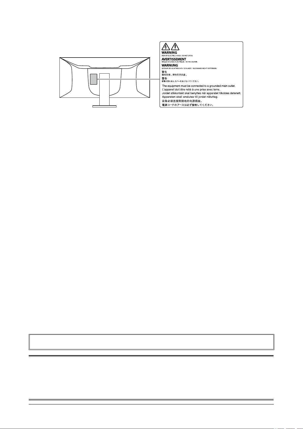
Location of Caution Statement
This product has been adjusted specically for use in the region to which it was originally shipped. If
operated outside this region, the product may not perform as stated in the specications.
No part of this manual may be reproduced, stored in a retrieval system, or transmitted, in any form or by
any means, electronic, mechanical, or otherwise, without the prior written permission of EIZO Corporation.
EIZO Corporation is under no obligation to hold any submitted material or information condential unless
prior arrangements are made pursuant to EIZO Corporation’s receipt of said information. Although every
eort has been made to ensure that this manual provides up-to-date information, please note that EIZO
monitor specications are subject to change without notice.
2
Page 3

Notice for this monitor
About the Usage of This Product
This product is suited to general purposes like creating documents, viewing multimedia content (Assuming
usage of approximately 12 hours per day).
If using this product for the following kinds of applications, where an extremely high degree of reliability and
safety is required, then measures should be in place to maintain safety while using this product.
• Transportation equipment (ships, aircraft, trains, and automobiles)
• Safety devices (Disaster prevention systems, security control systems, etc.)
• Life-critical devices (medical devices, such as life-support devices and operating room devices)
• Nuclear energy control devices (Nuclear energy control systems, security control systems of nuclear facilities, etc.)
• Major system communication devices (operation control systems of transportation systems, air trac control systems, etc.)
This product has been adjusted specically for use in the region to which it was originally shipped. If the
product is used outside the region, it may not operate as specied in the specications.
This product may not be covered by warranty for uses other than those described in this manual.
The specications noted in this manual are only applicable when the following are used:
• Power cords provided with the product
• Signal cables specied by us
Only use optional products manufactured or specied by us with this product.
About the LCD Panel
It takes about 30 minutes (under our measurement conditions) for the monitor display to stabilize. Please
wait 30 minutes or more after the monitor power has been turned on, and then adjust the monitor.
Monitors should be set to a lower brightness to prevent a loss in the screen quality caused by long-term use
and to maintain stable use.
When the screen image is changed after displaying the same image for extended periods of time, an
afterimage may appear. Use the screen saver or power save function to avoid displaying the same image for
extended periods of time. Depending on the image, an afterimage may appear even if it was displayed for
a short period of time. To remove such a phenomenon, change the image or keep the power turned o for
several hours.
If the monitor displays continuously over a long period of time, dark smudges or burn-in may appear. To
maximize the life of the monitor, we recommend the monitor be turned o periodically.
The LCD panel is manufactured using high-precision technology. Although, missing pixels or lit pixels may
appear on the LCD panel, this is not a malfunction. Percentage of eective dots: 99.9994 % or higher.
The backlight of the LCD panel has a xed lifetime. Depending on the usage pattern, such as usage for
long continuous periods, the lifespan of the backlight may run out sooner, requiring replacement. When the
screen becomes dark or begins to icker, please contact your local EIZO representative.
Do not press on the LCD panel or edge of the frame strongly, as this may result in display malfunctions, such
as interference patterns, etc. If pressure is continuously applied to the LCD panel surface, the liquid crystal
may deteriorate or the LCD panel may be damaged. (If the pressure marks remain on the panel, leave the
monitor with a black or white screen. The symptom may disappear.)
Do not scratch or press on the LCD panel with any sharp objects, at this may result in damage to the LCD
panel. Do not attempt to brush with tissues as this may scratch the panel.
Notice for this monitor
3
Page 4

About the Installation
If you place this product on a lacquer-coated desk, the color may adhere to the bottom of the stand due to
the composition of the rubber. Check the desk surface before use.
When the monitor is cold and brought into a room or the room temperature goes up quickly, dew
condensation may occur on the interior and exterior surfaces of the monitor. In that case, do not turn the
monitor on. Instead wait until the dew condensation disappears, otherwise it may cause some damage to the
monitor.
About the Maintenance
Periodic cleaning is recommended to keep the monitor looking new and to prolong its operation lifetime (refer
to “Cleaning” (page 4)).
Cleaning
The stains on the cabinet and LCD panel surface can be removed by moistening part of a soft cloth with
water or by using ScreenCleaner (available as an option).
Attention
• Chemicals such as alcohol and antiseptic solution may cause gloss variation, tarnishing, and fading of the cabinet
or LCD panel, and also quality deterioration of the image.
• Never use thinner, benzine, wax, or abrasive cleaner as they may damage the cabinet or LCD panel surface.
To use the monitor comfortably
• An excessively dark or bright screen may aect your eyes. Adjust the brightness of the monitor
according to the environmental conditions.
• Staring at the monitor for a long time tires your eyes. Take a 10-minute rest every hour.
Notice for this monitor
4
Page 5

CONTENTS
Notice for this monitor ......................................... 3
Cleaning .................................................................... 4
To use the monitor comfortably ............................. 4
CONTENTS ............................................................. 5
Chapter 1 Introduction ....................................... 6
1-1. Features ......................................................... 6
Curved Monitor ................................................ 6
●
Free Layout ..................................................... 6
●
Linking the Input Signal and USB Port ........... 6
●
Docking Station Function ................................ 6
●
Support for DisplayPort Alt Mode / USB
●
Power Delivery ................................................ 7
Reduction of Power Consumption .................. 7
●
Realizing More Convenient Operations
●
Using Screen InStyle ...................................... 8
1-2. Controls and Functions ............................... 8
Front ................................................................ 8
●
Rear ................................................................. 9
●
1-3. Supported Resolutions ...............................10
DisplayPort .....................................................10
●
HDMI ..............................................................11
●
USB-C ............................................................12
●
1-4. Changing the Computer Display Settings ...13
Windows 10 ....................................................13
●
Windows 8.1 ...................................................13
●
macOS ...........................................................13
●
Chapter 2 Basic Adjustment / Setting ............ 14
2-1. Switch Operation Method ...........................14
2-2. Switching Input Signals ..............................15
2-3. Switching Display Modes (Color Modes) ...15
Display Modes ................................................15
●
2-4. Adjusting Brightness ..................................16
2-5. Adjusting Volume.........................................16
Chapter 3 Advanced Adjustment / Setting .... 17
3-1. Basic Operation of the Setting Menu ........17
3-2. Setting Menu Functions ..............................18
Color Adjustment ............................................18
●
Signal Settings ...............................................21
●
Preference Settings ...................................... 23
●
EcoView Settings .......................................... 25
●
Language ...................................................... 26
●
Information .................................................... 26
●
Chapter 4 Connecting Multiple PCs ............... 27
4-1. Connecting Multiple PCs ........................... 27
Connection examples ................................... 27
●
4-2. Using PbyP Display .................................... 28
PbyP Settings ................................................ 28
●
Swapping the Main Window of Three
●
Window Display ............................................. 30
4-3. Linking the Input Signal and USB Port .....31
Connection Example ......................................31
●
Chapter 5 Administrator Settings ................... 33
5-1. Basic Operation of the “Administrator
Settings” Menu ............................................ 33
5-2. Functions of the “Administrator
Settings” Menu ............................................ 34
Chapter 6 Troubleshooting .............................. 36
6-1. No Picture .................................................... 36
6-2. Imaging Problems ....................................... 38
6-3. Other Problems ........................................... 39
Chapter 7 Attaching/Removing the Stand ..... 41
7-1. Removing the Stand ....................................41
7-2. Attaching the Optional Arm ....................... 42
7-3. Attaching the original stand ...................... 43
Chapter 8 Reference ........................................ 44
8-1. Using the Docking Station Function ........ 44
Connection Procedure .................................. 44
●
8-2. Specications ............................................. 46
Accessories ....................................................47
●
Appendix .............................................................. 48
Trademark ............................................................... 48
License .................................................................... 48
CONTENTS
5
Page 6
Chapter 1 Introduction
Thank you very much for choosing an EIZO color LCD monitor.
1-1. Features
Curved Monitor
●
This monitor comes equipped with a curved LCD panel with a resolution of 3840 x 1600. Two
windows can be aligned side-by-side for seamless display.
Free Layout
●
This monitor comes equipped with a PbyP (Picture by Picture) function that can display multiple input
signals at the same time. Three window Picture by Picture (3 PbyP) display and two window Picture
by Picture (2 PbyP) display are possible.
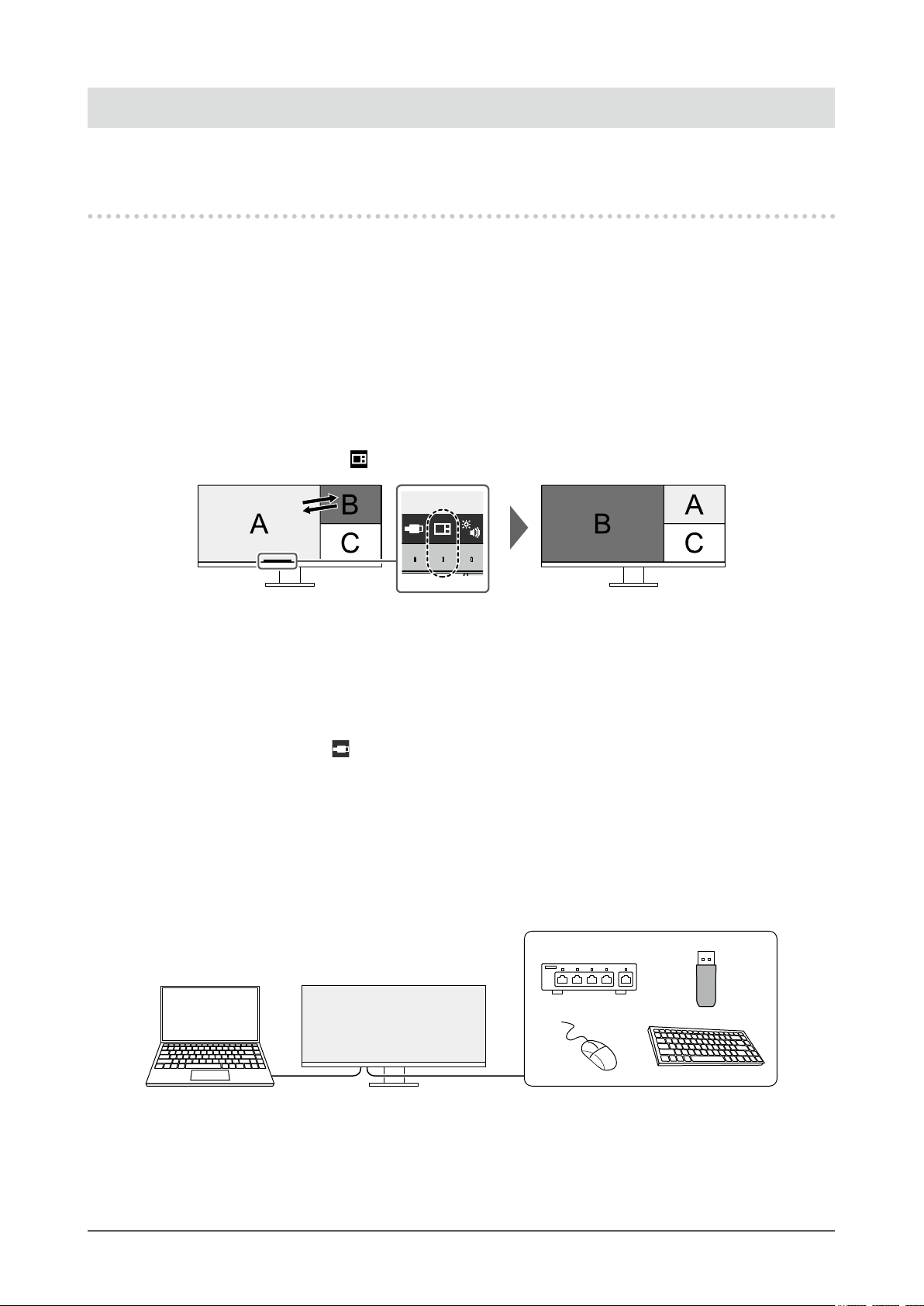
When using three window Picture by Picture (3 PbyP) display, you can swap the main window by
selecting the operation switch (
) on the front of the monitor. (page 30)
Linking the Input Signal and USB Port
●
When two or three PCs are connected to one monitor, you can link the input signals with the USB
upstream ports. This allows you to use a USB device connected to the monitor from multiple PCs by
switching between them.
Select the operation switch (
(page 32)
Docking Station Function
●
This product is equipped with a LAN port and USB hub so that it can be used as a docking station.
By connecting a USB Type-C® (hereinafter USB-C®) cable, you can create a stable network
environment even on notebook PCs or tablet devices that are not equipped with LAN ports. You can
also use USB-compatible peripheral devices and charge smartphones. (page 44)
) on the front of the monitor to swap to an enabled USB upstream port.
Chapter 1 Introduction
6
Page 7
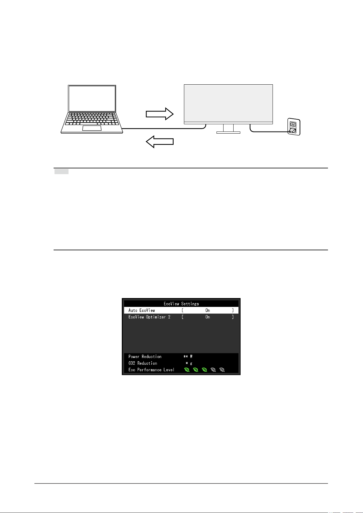
Support for DisplayPort Alt Mode / USB Power Delivery
●
This product is equipped with a USB-C connector and supports the transmission of video signals
(DisplayPort Alt Mode) as well as the charging of USB devices (USB Power Delivery).
It supplies a maximum of 85 W of power to a connected notebook PC when used as an external
monitor.
Video signals
Power supply
Note
• To use the charging function, the connected device must support device charging by using USB Power
Delivery. Charging may not be possible depending on the connected external device.
• Only when one of the following USB-C cables is used, a maximum power of 85 W can be supplied.
- CC200SS-5A or CC200SSW-5A (Included)
- CC100 (Separately sold accessory)
• To display video signals, the connected device must support DisplayPort over USB Type-C (DisplayPort Alt
Mode).
• Connected devices can be charged even when the monitor is in power saving mode.
• When “Compatibility Mode” is set to “On” in the “Administrator Settings” menu, connected devices can be
charged even when the power of the monitor is turned o.
Reduction of Power Consumption
●
This product provides a function that automatically adjusts the screen brightness to reduce power
consumption *1. Power Reduction, CO2 Reduction, and Eco Performance Level can be checked on
the "EcoView Settings" menu. (page 25)
• Auto EcoView
The ambient light sensor on the front of the monitor detects the ambient brightness to automatically
adjust the screen brightness to a comfortable level.
• EcoView Optimizer 2
The monitor automatically adjusts the screen brightness according to the white level of the input
signal. This function can reduce power consumption while maintaining the brightness specied by
the input signal.
*1 Reference values
Maximum power consumption: 194 W (when a USB device is connected and the speakers are working),
standard power consumption: 28 W (brightness 120 cd/m
speakers are not working, at default settings)
2
, when no USB device is connected and the
Chapter 1 Introduction
7
Page 8
Realizing More Convenient Operations Using Screen InStyle
3
54
1 1
2
●
The "Screen InStyle" monitor control utility enables you to use the monitor more conveniently.
• The monitor color mode can be switched automatically to suit the software to be used.
• You can switch input signals using the shortcut keys on the keyboard.
• When multiple monitors are installed, you can turn the power on and o or change the color mode
of all monitors at the same time.
Note
• Screen InStyle can be downloaded from our web site (www.eizoglobal.com).
• The Windows operating systems are only supported.
1-2. Controls and Functions
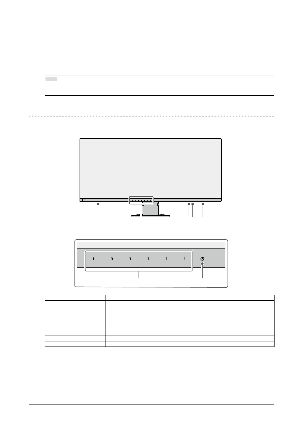
Front
●
1. Speakers Outputs audio.
2. Ambient light sensor Detects ambient brightness. If you use Auto EcoView, the screen brightness is
automatically adjusted according to the ambient brightness (page 25).
3. Power indicator Indicates the monitor’s operation status.
White: Normal operation mode
Orange: Power saving mode
OFF: Main power / power o
4. Operation switches Displays menus. Operate the switches according to the operation guide (page 17).
5. Power switch Turns the power on or o.
Chapter 1 Introduction
8
Page 9
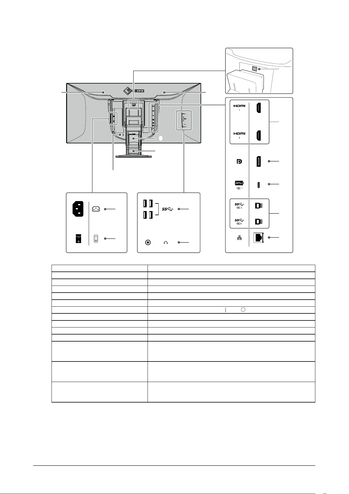
Rear
6
●
8
6
15
9
10
16
7
17
11
12
6. Handle This handle is used for transportation.
7. Security lock slot Complies with Kensington’s MicroSaver security system.
8. Lock button Use this button to remove the monitor from the stand.
9. Cable holder Stores the cables.
10. Stand
11. Power connector Connects the power cord.
12. Main power switch
13. USB-A connector (downstream) Connects to a peripheral USB device (page 44).
14. Headphone jack Connects to headphones.
15. HDMI connector Connects to a PC with HDMI output.
16. DisplayPort connector Connects to a PC with DisplayPort output.
17. USB-C connector (upstream) Connects to a PC with USB-C output. This also transmits the
18. USB-B connector (upstream) Connect the USB cable when using software that requires USB
19. LAN port (RJ-45) When using a network connection with the docking station function
*1 By removing the stand from the monitor, it is possible to attach the monitor to a dierent stand or arm.
*1
Adjusts the height and angle (tilt and swivel) of the monitor.
Turns the main power on or o.
USB signal that is necessary for using software that requires USB
connection or when using the docking station function (page 44).
connection. This makes it possible to connect USB devices such as a
mouse or keyboard to the monitor and use them from multiple PCs.
(page 44), this connects to a network hub or router with a LAN
cable.
13
14
18
19
: On, : O
Chapter 1 Introduction
9
Page 10
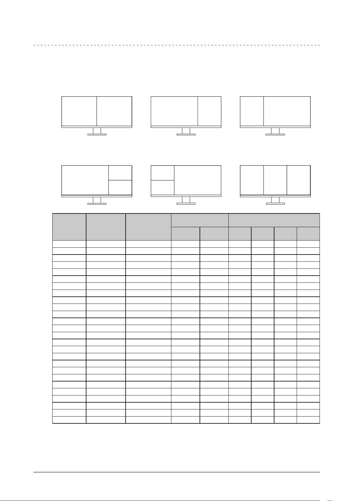
1-3. Supported Resolutions
The monitor supports the following resolutions.
DisplayPort
●
Two window display (2 PbyP)
Layout 1 Layout 2 Layout 3
PbyP-A PbyP-A
PbyP-CPbyP-B PbyP-BPbyP-C
Three window display (3 PbyP)
Layout 1 Layout 2 Layout 3
PbyP-D
PbyP-B
PbyP-D
Vertical Scan
Resolution
Frequency
Scan Format
(Hz)
640 × 480 59.940 Progressive √ √ √ √ √ √
640 × 480 60.000 Progressive √ √ √ √ √ √
720 × 400 70.087 Progressive √ √ √ √ √ √
720 × 480 59.940 Progressive √ √ √ √ √ √
720 × 480 59.941 Progressive √ √ √ √ √ √
720 × 480 60.000 Progressive √ √ √ √ √ √
800 × 600 6 0.317 Progressive √ √ √ √ √ √
1024 × 768 60.004 Progressive √ √ √ √ √ √
1280 × 720 59.855 Progressive √ √ √ √ √ √
1280 × 720 59.940 Progressive √ √ √ √ √ √
1280 × 720 59.979 Progressive √ √ √ √ √ √
1280 × 720 60.000 Progressive √ √ √ √ √ √
1280 × 800 59.810 Progressive √ √ √ √ √ √
1280 × 800 59.910 Progressive √ √ √ √ √ √
1280 × 1024 60.020 Progressive √ √ √ √ √ √
1280 × 1600 59.910 Progressive - - - - √
1600 × 900 60.000 Progressive √ √ √ - - -
1600 × 1200 60.000 Progressive √ √ √ - - 1680 × 1050 59.883 Progressive √ √ √ - - 1680 × 1050 59.954 Progressive √ √ √ - - 1920 × 1080 59.940 Progressive √ √ √ √ - √
1920 × 1080 60.000 Progressive √ √ √ √ - √
1920 × 1600 59.950 Progressive - - √
2560 × 1600 59.972 Progressive √ √ - √
3840 × 1600 29.998 Progressive √
3840 × 1600 59.994 Progressive - √
*1 The applicable signal varies depending on the “Signal Format” settings (refer to “Signal Format” (page 35))
*2 Recommended resolution
*3 Displayed at reduced size
*4 Native resolution of the display area
PbyP-D
PbyP-D
PbyP-B
Single Window
Display
Version
Version
1.1
*2
PbyP-C PbyP-C PbyP-C
*2
PbyP Display
*2
- - -
*2
- √
*1
1.2
PbyP-A PbyP-B PbyP-C PbyP-D
√ - - - -
*2
- - - -
*4
*4
*3
-
*3
*3
*2 *3
Chapter 1 Introduction
10
Page 11
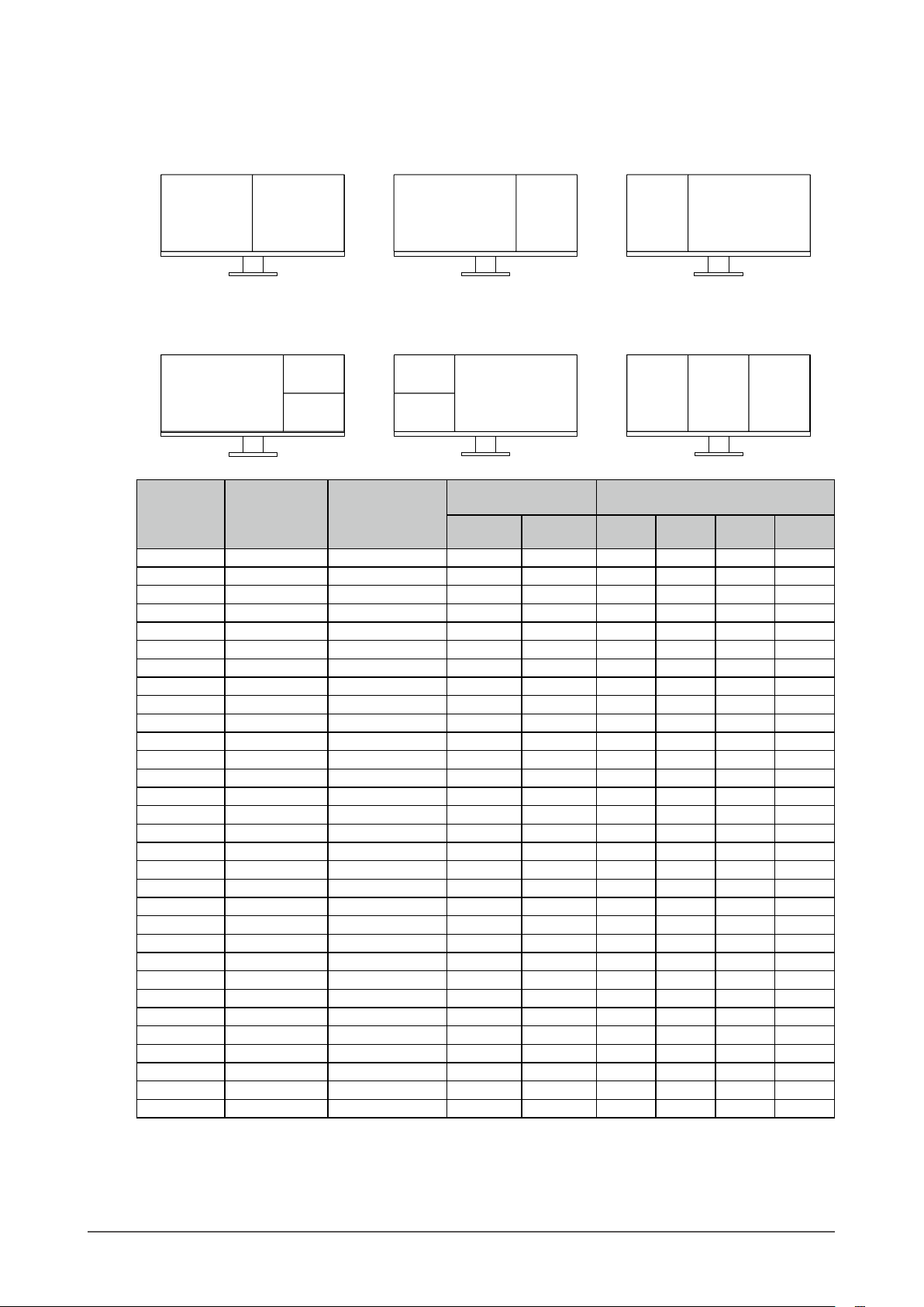
HDMI
●
Two window display (2 PbyP)
Layout 1 Layout 2 Layout 3
PbyP-A PbyP-A
PbyP-CPbyP-B PbyP-BPbyP-C
Three window display (3 PbyP)
Layout 1 Layout 2 Layout 3
PbyP-D
PbyP-B
PbyP-D
Vertical Scan
Resolution
Frequency
Scan Format
(Hz)
640 × 480 59.940 Progressive √ √ √ √ √ √
640 × 480 60.000 Progressive √ √ √ √ √ √
720 × 400 70.087 Progressive √ √ √ √ √ √
720 × 480 59.940 Progressive √ √ √ √ √ √
720 × 480 59.941 Progressive √ √ √ √ √ √
720 × 480 60.000 Progressive √ √ √ √ √ √
720 × 576 50.000 Progressive √ √ √ √ √ √
800 × 600 6 0.317 Progressive √ √ √ √ √ √
1024 × 768 60.004 Progressive √ √ √ √ √ √
1280 × 720 50.000 Progressive √ √ √ √ √ √
1280 × 720 59.855 Progressive √ √ √ √ √ √
1280 × 720 59.940 Progressive √ √ √ √ √ √
1280 × 720 59.979 Progressive √ √ √ √ √ √
1280 × 720 60.000 Progressive √ √ √ √ √ √
1280 × 800 59.810 Progressive √ √ √ √ √ √
1280 × 800 59.910 Progressive √ √ √ √ √ √
1280 × 1024 60.020 Progressive √ √ √ √ √ √
1280 × 1600 59.910 Progressive - - - - √
1600 × 900 60.000 Progressive √ √ √ - - -
1600 × 1200 60.000 Progressive √ √ √ - - 1680 × 1050 59.883 Progressive √ √ √ - - 1680 × 1050 59.954 Progressive √ √ √ - - 1920 × 1080 50.000 Progressive √ √ √ √ - √
1920 × 1080 59.940 Progressive √ √ √ √ - √
1920 × 1080 59.940 Interlace √ √ √ √ - √
1920 × 1080 60.000 Progressive √ √ √ √ - √
1920 × 1080 60.000 Interlace √ √ √ √ - √
1920 × 1600 59.950 Progressive - - √
2560 × 1600 59.972 Progressive √ √ - √
3840 × 1600 29.998 Progressive √ √
3840 × 1600 59.994 Progressive √
*1 The applicable signal varies depending on the “Signal Format” settings (refer to “Signal Format” (page 35))
*2 Recommended resolution
*3 Displayed at reduced size
*4 Native resolution of the display area
PbyP-D
PbyP-D
PbyP-B
Single Window
Display
WQHD+
WQHD+
60Hz
*2
PbyP-C PbyP-C PbyP-C
*2
PbyP Display
*2
- - -
*2
- √
*1
30H
PbyP-A PbyP-B PbyP-C PbyP-D
z
*2
- - - -
- - - - -
*4
*4
*3
-
*3
*3
*3
*3
*3
*2 *3
Chapter 1 Introduction
11
Page 12
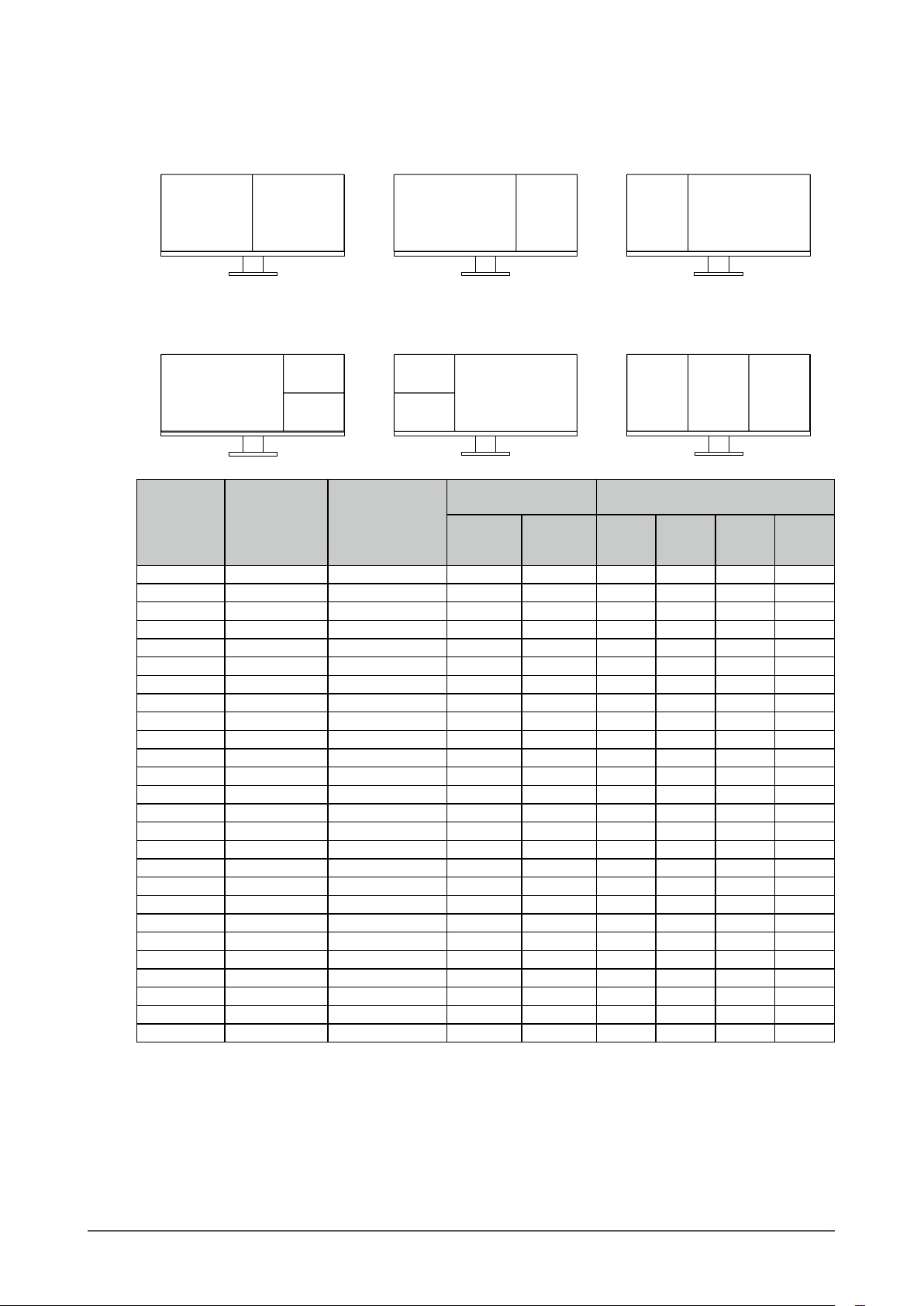
USB-C
●
Two window display (2 PbyP)
Layout 1 Layout 2 Layout 3
PbyP-A PbyP-A
PbyP-CPbyP-B PbyP-BPbyP-C
Three window display (3 PbyP)
Layout 1 Layout 2 Layout 3
PbyP-D
PbyP-B
PbyP-D
Vertical Scan
Resolution
Frequency
Scan Format
(Hz)
640 × 480 59.940 Progressive √ √ √ √ √ √
640 × 480 60.000 Progressive √ √ √ √ √ √
720 × 400 70.087 Progressive √ √ √ √ √ √
720 × 480 59.940 Progressive √ √ √ √ √ √
720 × 480 59.941 Progressive √ √ √ √ √ √
720 × 480 60.000 Progressive √ √ √ √ √ √
800 × 600 6 0.317 Progressive √ √ √ √ √ √
1024 × 768 60.004 Progressive √ √ √ √ √ √
1280 × 720 59.855 Progressive √ √ √ √ √ √
1280 × 720 59.940 Progressive √ √ √ √ √ √
1280 × 720 59.979 Progressive √ √ √ √ √ √
1280 × 720 60.000 Progressive √ √ √ √ √ √
1280 × 800 59.810 Progressive √ √ √ √ √ √
1280 × 800 59.910 Progressive √ √ √ √ √ √
1280 × 1024 60.020 Progressive √ √ √ √ √ √
1280 × 1600 59.910 Progressive - - - - √
1600 × 900 60.000 Progressive √ √ √ - - -
1600 × 1200 60.000 Progressive √ √ √ - - 1680 × 1050 59.883 Progressive √ √ √ - - 1680 × 1050 59.954 Progressive √ √ √ - - 1920 × 1080 59.940 Progressive √ √ √ √ - √
1920 × 1080 60.000 Progressive √ √ √ √ - √
1920 × 1600 59.950 Progressive - - √
2560 × 1600 59.972 Progressive √ √ - √
3840 × 1600 29.998 Progressive √ √
3840 × 1600 59.994 Progressive √
*1 The applicable signal varies depending on the “Signal Format” settings (refer to “Signal Format” (page 35))
*2 Recommended resolution
*3 Displayed at reduced size
*4 Native resolution of the display area
PbyP-D
PbyP-D
PbyP-B
Single Window
Display
WQHD+
WQHD+
60Hz /
USB2.0
*2
USB3.1
PbyP-C PbyP-C PbyP-C
*2
PbyP Display
*2
- - -
*2
- √
*1
30Hz /
*2
PbyP-A PbyP-B PbyP-C PbyP-D
- - - -
- - - - -
*4
*4
*3
-
*3
*3
*2 *3
Chapter 1 Introduction
12
Page 13

1-4. Changing the Computer Display Settings
If the image is not displayed properly after connecting the monitor to a PC, follow the procedure below to
change the display settings on the computer.
Windows 10
●
1. Right-click the mouse anywhere on the desktop except on icons. A menu is displayed.
2. From the displayed menu, click “Display Settings”. The “Settings” screen is displayed.
3. If multiple monitors, including notebook PC screens, are connected to the computer, select “Extend
these displays” in the “Multiple displays” menu, and then click “Keep changes” on the conrmation
screen. After changing the settings, select a monitor in the “Select and rearrange displays” menu.
4. Select the “Make this my main display” option in the “Multiple displays” menu. This enables the
monitor to display images properly.
5. Conrm that the recommended resolution for the monitor is set in the “Resolution” menu.
(“(Recommended)” is displayed after the resolution.)
6. To change the size of text and icons, select a magnication in the menu of zoom percentages
according to personal preference.
7. If a message prompting you to sign out is displayed after changing the settings, sign out and then
sign in again.
Windows 8.1
●
1. Click the “Desktop” tile on the Start Screen to display the desktop.
2. Right-click the mouse anywhere on the desktop except on icons. A menu is displayed.
3. From the displayed menu, click “Screen resolution”. The settings screen is displayed.
4. If multiple monitors, including notebook PC screens, are connected to the computer, select “Extend
these displays” in the “Multiple displays” menu, and then click “Apply”. Click “Keep changes” on
the conrmation screen.
5. Select a monitor in the “Display” menu, and then select the “Make this my main display” option
and click “Apply”. This enables the monitor to display images properly.
6. Conrm that the recommended resolution for the monitor is set in the “Resolution” menu.
(“(recommended)” is displayed after the resolution.)
7. To change the size of text and icons, click “Make text and other items larger or smaller”, select a
size according to personal preference on the settings screen, and then click “Apply”.
8. If a message prompting you to sign out/log o is displayed after changing the settings, sign out/
log o and then sign in/log in again.
macOS
●
1. Select “System Preferences” from the Apple menu.
2. When the “System Preferences” panel is displayed, click “Displays”.
3. If multiple monitors, including notebook PC screens, are connected to the computer, make sure
that “Mirror Displays” is not selected on the “Arrangement” tab. If it is selected, remove the check
mark.
4. Select the “Display” tab, and make sure that “Default for display” is selected for “Resolution”. If
it is not selected, add a check mark. The correct resolution has now been set for your display.
Close the “System Preferences” panel. If multiple monitors, including notebook PC screens, are
connected to the computer, congure these settings in “Display” on each monitor.
5. To select a resolution according to personal preference, select “Scaled” and then select a
resolution (either from a list or icons), and then close the panel.
Chapter 1 Introduction
13
Page 14
Chapter 2 Basic Adjustment / Setting
The input signals and display modes of this monitor can be switched according to your usage environment
and preferences.
This chapter describes the basic functions that can be adjusted and set using the switches on the front of the
monitor.
For advanced adjustment and setting procedures using the Setting menu, see “Chapter 3 Advanced
Adjustment / Setting” (page 17).
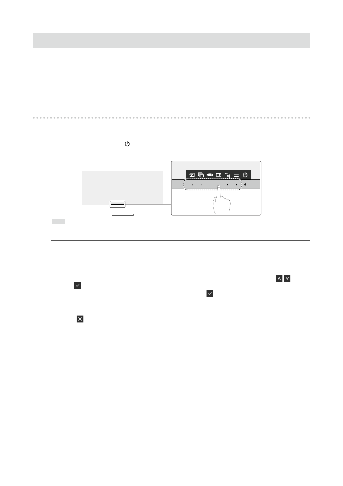
2-1. Switch Operation Method
Displaying the operation guide
1.
1. Touch any switch (except ).
The operation guide appears on the screen.
Note
• Do not directly touch the operation guide that appears on the screen. There are switches below the operation
guide that can be touched to perform adjustment / setting.
Adjusting / setting
2.
1. Touch a switch for adjustment / setting.
The Adjustment / Setting menu appears.
(A submenu may also be displayed. In this case, select the item for adjustment / setting using
select
2. Perform adjustment / setting with the switches and select to accept the changes.
Exiting
3.
1. Select to exit the menu.
.)
and
Chapter 2 Basic Adjustment / Setting
14
Page 15

2-2. Switching Input Signals
When a monitor has multiple signal inputs, the signal to display on-screen can be changed.
For details on PbyP, see “4-2. Using PbyP Display” (page 28).
Note
• "Screen InStyle" allows you to switch input signals using the shortcut keys on the keyboard.
2-3. Switching Display Modes (Color Modes)
This product is preinstalled with color modes for various display purposes.
By switching the mode according to the purpose and contents of the display, you can display images in
an appropriate manner.
Display Modes
●
Color Mode Purpose
User1
User2
sRGB
Paper
Movie
DICOM
Note
• "Screen InStyle" allows you to select the color mode automatically according to the software in use.
• In Paper mode, the amount of blue light emitted from the screen is reduced by changing the color tone and
controlling the brightness.
Select either of these modes to set a user-dened display mode.
Select this mode to display colors in the sRGB color gamut on Windows (unnecessary for
macOS).
Note
• This product is equipped with an LCD panel that has a wider color gamut than sRGB.
This mode uses color tones and contrast similar to that of paper to produce a printed
paper eect. It is suitable for displaying images from media such as books and documents.
This mode displays moving images brightly and with a clear-cut three-dimensional
appearance. It is suitable for playing back video content.
Select this mode to simply display medical purpose digital images based on DICOM® Part
14.
Attention
• This is not intended to be used for diagnostic purposes.
Chapter 2 Basic Adjustment / Setting
15
Page 16

2-4. Adjusting Brightness
The brightness of the screen can be adjusted to suit the installation environment or personal preference.
The screen brightness is adjusted by changing the brightness of the backlight (light source from the LCD
back panel).
Setting Value
0 to 100
2-5. Adjusting Volume
The volume of the speakers and headphones can be set individually.
Setting Value
0 to 30
Speaker volume
Headphone volume (when the
headphones are connected)
Chapter 2 Basic Adjustment / Setting
16
Page 17

Chapter 3 Advanced Adjustment / Setting
This chapter describes the advanced monitor adjustment and setting procedures using the Setting menu.
For basic functions, see “Chapter 2 Basic Adjustment / Setting” (page 14).
3-1. Basic Operation of the Setting Menu
Menu display
1.
1. Touch any switch (except ).
The operation guide appears.
2. Select .
The Setting menu appears.
Adjusting / setting
2.
1. Select a menu to adjust / set with
The Sub menu appears.
2. Select an item to adjust / set with and select .
The Adjustment / Setting menu appears.
and select .
3. Perform adjustment / setting with or and select to accept the changes.
The Sub menu appears.
Selecting
making changes.
Exiting
3.
1. Selecting several times will terminate the Setting menu.
during adjustment / setting will cancel the adjustment / setting and restore the state prior to
Chapter 3 Advanced Adjustment / Setting
17
Page 18

3-2. Setting Menu Functions
Color Adjustment
●
The color mode settings can be adjusted according to personal preference.
Functions that can be adjusted dier depending on the color mode.
Function
Brightness
Contrast
Temperature
Gamma
Super Resolution
Advanced
Settings
Reset
Overdrive
Hue
Saturation
Gain
User1
User2
√ √ √ √
√
√
√
√
√
√
√
√
√ √ √ √
√: Adjustable -: Not adjustable
Color Mode
sRGB Paper Movie DICOM
-
- -
-
- - - -
-
- - - -
- -
- -
- - - -
√ √
√ √
√
√
√
-
-
-
-
-
-
Attention
• It takes about 30 minutes for the monitor display to stabilize. Please wait 30 minutes or more after power to
the monitor has been turned on before adjusting the monitor.
• The same image may be observed in dierent colors on multiple monitors due to monitor-specic
characteristics. Make ne color adjustments visually when matching colors across multiple monitors. Follow
the procedure below to adjust and match colors across multiple monitors.
1. Display a white screen on each monitor.
2. Use one of the monitors as a visual reference point to make adjustments to the “Brightness”,
“Temperature”, and “Gain” of the other monitors.
• When Auto EcoView is set to “On”, the same brightness setting is shared by all of the color modes and cannot
be set individually for each color mode.
Chapter 3 Advanced Adjustment / Setting
18
Page 19

Function Setting Value Description
Color Mode User1
User2
sRGB
Paper
Movie
DICOM
Brightness 0 to 100
Contrast 0 to 100
Temperature O
4000 K to 10000
K
(in increments
of 500 K. 9300 K
is included.)
Gamma 1.8
2.0
2.2
2.4
Super Resolution O
1
2
Select the desired mode according to the monitor application.
The color mode settings can also be adjusted according to
personal preference. Select the mode for adjustment and perform
adjustment using the relevant functions.
Note
• For details on the adjustment status of each mode, see “2-3.
Switching Display Modes (Color Modes)” (page 15).
The screen brightness is adjusted by changing the brightness of
the backlight (light source from the LCD back panel).
Note
• If the image is too dark even when the brightness is set to 100,
adjust the contrast.
The brightness of the screen is adjusted by varying the video
signal level.
Note
• A contrast of 50 displays every color gradation.
• When adjusting the monitor, it is recommended to perform
brightness adjustment, which does not lose gradation
characteristics, prior to contrast adjustment.
• Perform contrast adjustment in the following cases.
- If the image is too dark even when the brightness is set to
100 (Set the contrast to higher than 50.)
Adjust the color temperature.
The color temperature is normally used to express the hue of
“White” and/or “Black” with a numerical value. The value is
expressed in degrees “K” (Kelvin).
The screen becomes reddish at low color temperatures and bluish
at high color temperatures, similar to the temperatures of a ame.
A gain preset value is set for each color temperature setting value.
Note
• The value shown in “K” is available only as a reference.
• “Gain” allows you to perform more advanced adjustment.
• If set to “O”, the image is displayed in the preset color of the
LCD panel (Gain: 100 for each RGB channel).
• When the gain is changed, the color temperature setting
changes to “O”.
Adjust the gamma.
While the brightness of the monitor varies depending on the
video level of the input signal, the variation rate is not directly
proportional to the input signal. Maintaining the balance between
the input signal and brightness of the monitor is referred to as
“Gamma correction”.
Note
• If “sRGB” is selected for the color mode, “sRGB” is displayed
for the gamma value.
• If “Paper” is selected for the color mode, “Paper” is displayed
for the gamma value.
• If “DICOM” is selected for the color mode, “DICOM” is
displayed for the gamma value.
Image blur can be reduced by enhancing its outline.
Select “1” or “2” (outlines are more enhanced than “1”) according
to personal preference.
Chapter 3 Advanced Adjustment / Setting
19
Page 20

Function Setting Value Description
Advanced
Settings
Reset - Reset any color adjustments for the currently selected color mode
Overdrive O
On
Hue -50 to 50
Saturation
Gain 0 to 100
-50 to 50 Adjust the color saturation.
This function allows you to set the overdrive based on the use of
the monitor.
Image lag can be reduced by using the “On” setting when
displaying moving images.
Note
• Depending on the display resolution and the setting of “Picture
Expansion” (page 21), overdrive may be set to “O”.
Adjust the hue.
Note
• Using this function may prevent some color gradations from
being able to be displayed.
Note
• Using this function may prevent some color gradations from
being able to be displayed.
• The minimum value (-50) changes the screen to monochrome.
The brightness of each red, green, and blue color component
is referred to as “Gain”. The hue of “white” can be changed by
adjusting the gain.
Note
• Using this function may prevent some color gradations from
being able to be displayed.
• The gain value changes according to the color temperature.
• When the gain is changed, the color temperature setting
changes to “O”.
back to the default settings.
Chapter 3 Advanced Adjustment / Setting
20
Page 21

Signal Settings
●
Set the details regarding input signal, such as the screen display size and color format.
Function Setting Value Description
Window Selection Left
Right
Center
Upper Left
Upper Right
Lower Left
Lower Right
Picture Expansion Auto
Full Screen
Aspect Ratio
Dot by Dot
*1
*2
Select the window to apply the “Signal Settings” to during PbyP
display. For details on layouts for PbyP display, see “4-2. Using
PbyP Display” (page 28).
Note
• Enabled only during PbyP display.
• If an appropriate signal is not input, a setting value cannot
be selected.
The screen size of the monitor display can be changed.
• “Auto”
The monitor automatically changes the screen size
according to the aspect ratio and resolution information
from the PC.
• “Full Screen”
Images are stretched to full screen. Since aspect ratios are
not maintained, images may be distorted in some cases.
• “Aspect Ratio”
Images are enlarged to full screen without changing the
aspect ratio. Since aspect ratios are maintained, blank
horizontal or vertical borders may appear.
• “Dot by Dot”
Displays the image at the set resolution or size specied by
the input signal.
Note
• Example settings
- Full Screen
*1 The selectable values depend on the layout
*2 Only enabled during HDMI input
- Aspect Ratio
- Dot by Dot
(input signal)
Chapter 3 Advanced Adjustment / Setting
21
Page 22

Function Setting Value Description
Input Color Format Auto
YUV 4:2:2
YUV 4:4:4
YUV
*1
*1
*2
RGB
Input Range Auto
Full
Limited
*1 Only enabled during HDMI input
*2 Only valid for DisplayPort or USB-C input
The color format of the input signal can be specied.
Try changing this setting if colors are not displayed correctly.
Depending on the video reproduction device, there may be a
restriction on black and white video signal levels output to the
monitor. This kind of signal is called “Limited range”. On the
other hand, unlimited signals are called “Full range”.
• “Auto”
Input signal brightness range is automatically judged and is
displayed appropriately (recommended setting). Depending
on the video reproduction device, Limited range and Full
range may not be able to be judged by the monitor. In
such a case, selecting “Full” or “Limited” will allow it to be
displayed appropriately.
• “Full”
To be selected in case of Full range signals. Appropriate
display can be obtained when this is selected, in case both
blacks and whites are corrupted.
• “Limited”
To be selected in case of Limited range signals. In case this
is selected, the output signal range is expanded from 0 to
255 to obtain an appropriate display when black is pale and
white is dull.
Note
• When “YUV” is selected in “Input Color Format”, the setting
is automatically set to “Limited”. Additionally, when “Auto” is
selected and the monitor determines the input color format
to be YUV, the setting is automatically set to “Limited”.
Chapter 3 Advanced Adjustment / Setting
22
Page 23

Preference Settings
●
The monitor’s settings can be congured to suit the usage environment or personal preference.
Function Setting Value Description
Power Save On
O
Power Indicator On
O
The monitor can be set to enter power saving mode according
to the state of the PC.
The monitor changes to power saving mode about 15 seconds
after signal input ceases to be detected.
When the monitor has shifted to power saving mode, images
are not displayed on the screen and audio is not output.
• How to exit power saving mode
- Press the operation switches (excluding
of the monitor
- The monitor automatically exits power saving mode when
the monitor receives input
Note
• At the time of shifting to power saving mode, a message
that indicates the transition is displayed 5 seconds in
advance.
• For PbyP display, if there is no signal input for all connected
PCs, the monitor shifts to power saving mode.
• When not using the monitor, you can turn o the main power
supply or disconnect the power plug so that the power is cut
completely.
• When “Compatibility Mode” (page 34) is set to “On”,
even if the monitor shifts to power saving mode, devices
connected to the USB downstream port are operational.
Therefore, power consumption of the monitor varies with
connected devices even in power saving mode.
The power indicator (white) can be turned o in normal
operation mode.
) on the front
Chapter 3 Advanced Adjustment / Setting
23
Page 24

Function Setting Value Description
USB
Selection
DisplayPort
HDMI 1
HDMI 2
USB-1 (USB-C)
USB-2
USB-3
When two or three PCs are connected to one monitor, you can
link the input signal with the USB upstream port. For details, see
“4-3. Linking the Input Signal and USB Port” (page 31).
The compatibility of setting values and USB connectors is as
follows.
USB-1 (USB-C) : USB-C connector (upstream)
USB-2 : USB-B connector (upstream)
USB-3 : USB-B connector (upstream)
Note
• In the default settings, “USB-2” is set for all input signals.
Change the settings so that they do not overlap.
• When you want to change settings and there is a storage
device such as USB memory connected to the monitor,
change settings only after you have removed the storage
device. In failing to do so, data may be lost or damaged.
• You cannot change the keyboard layout.
Sound Selection (PbyP) Left
Right
Upper Right
Lower Right
Upper Left
Lower Left
*1
Center
Monitor Reset - Restore all settings to their default values except for the
*1 The selectable values depend on the layout
Select the source of audio to output from the monitor during
PbyP display. For details on layouts for PbyP display, see “4-2.
Using PbyP Display” (page 28).
Note
• Enabled only during PbyP display.
following settings.
• Settings on the “Administrator Settings” menu
• Settings for PbyP display
• “USB Selection” in the “Preferences” menu
Chapter 3 Advanced Adjustment / Setting
24
Page 25

EcoView Settings
●
This monitor is equipped with EcoView functions to enable users to conserve energy.
If you use Auto EcoView, which is one of the EcoView functions, the screen brightness is
automatically adjusted according to the ambient brightness.
Function Setting Value Description
Auto EcoView
EcoView Optimizer 2
On
O
On
O
The ambient light sensor on the front of the monitor detects the
ambient brightness to automatically adjust the screen brightness
to a comfortable level using Auto EcoView. The power
consumption of the backlight can be curtailed by adjusting the
brightness to an appropriate level.
This function can also mitigate eye strain and tiredness caused
by a screen that is too bright or too dark.
Note
• Be careful not to block the ambient light sensor on the lower
side of the monitor when using Auto EcoView.
• Even if Auto EcoView is set to “On”, the “Brightness” can
be changed in Color, according to your preferences. The
manner in which Auto EcoView changes the brightness will
also vary depending on the value you set.
• When “DICOM” is selected for the color mode, the Auto
EcoView setting is turned “O”.
The monitor automatically adjusts the screen brightness
according to the white level of the input signal.
This function can reduce power consumption while maintaining
the brightness specied by the input signal.
Note
• The setting is turned “O” in the following cases:
- When “Movie” or “DICOM” is selected for the color mode
- When using PbyP display
• When set to “On”, the appearance of pale colors may
change. If this bothers you, set this function to “O”.
Note
• The power saving level (Power Reduction, CO2 Reduction, and Eco Performance Level) can be checked on
the “EcoView Settings” menu. The more indicators that light up representing the Eco Performance Level, the
higher the power saving level attained.
- Power Reduction: the reduction in the backlight’s power consumption as a result of the adjusted brightness
value.
- CO
Reduction: converted from the “Power Reduction” value, this is an estimate of the quantity of CO2
2
emissions reduced when using the monitor for 1 hour.
• The numeric value is a result of calculation based on a default setting (0.000555t-CO2 / kWh) determined by
a Japanese ministerial ordinance (2006, Ministry of Economy, Trade and Industry, Ministry of Environment,
civil code article 3) and may dier depending on country and year.
Chapter 3 Advanced Adjustment / Setting
25
Page 26

Language
●
The display language for menus and messages can be selected.
Setting Value
English, German, French, Spanish, Italian, Swedish, Japanese, Simplied Chinese, Traditional
Chinese
Attention
• The display language of the “Administrator Settings” menu cannot be changed.
Information
●
You can check the monitor information (model name, serial number (S/N), rmware version, usage
time) and the input signal information.
Example: • Single window display • PbyP display
Chapter 3 Advanced Adjustment / Setting
26
Page 27

Chapter 4 Connecting Multiple PCs
4-1. Connecting Multiple PCs
This product can be connected to multiple PCs and allows you to switch between the connections for
display.
Connection examples
●
HDMI
HH200PR
HDMI cable
(HDMI - HDMI)
(Included)
DisplayPort
PP200
DisplayPort cable
(DisplayPort - DisplayPor t)
(Included)
USB-C
CC200SS-5A
or
CC200SSW-5A
USB cable
(USB-C - USB-C)
(Included)
HDMI
Note
• You can select the input signal to display using the operation switch ( ) on the front of the monitor. For details,
see “2-2. Switching Input Signals” (page 15).
• This product provides a function that automatically recognizes the connector through which PC signals are input,
and displays images on the screen accordingly. For details, see “Auto Input Detection” (page 34).
DisplayPort
USB-C
Chapter 4 Connecting Multiple PCs
27
Page 28

4-2. Using PbyP Display
If you select PbyP display and input multiple signals to the monitor, you can display multiple windows
side-by-side. Up to three windows can be displayed on one screen, so switching signals is no longer
necessary and work productivity improves. The combination of signals can also be changed.
PbyP Settings
●
Two window display (2 PbyP)
Layout 1 Layout 2 Layout 3
Left Right
Function Setting Value Description
Layout Layout 1
Layout 2
Layout 3
Input Left
Right
USB-C
DisplayPort
HDMI 1
HDMI 2
Left Right Left Right
Select a layout.
Select an input signal for each window.
Chapter 4 Connecting Multiple PCs
28
Page 29

Three window display (3 PbyP)
Layout 1 Layout 2 Layout 3
Upper Left
Lower
Left
Right
(Main window)
Left
(Main window)
Upper Right
Lower Right
Function Setting Value Description
Layout Layout 1
Layout 2
Layout 3
Main Window Swap Upper Left
Upper Right
Lower Left
*1
Input Upper Left
Upper Right
Lower Left
Lower Right
Lower Right
USB-C
DisplayPort
HDMI 1
HDMI 2
Left
Right
*1
Center
*1 The item names displayed depend on the layout
Select a layout.
Select the window to use as the main window.
For details, refer to “Swapping the Main Window of Three Window
Display” (page 30).
Note
• This cannot be set for Layout 3.
Select an input signal for each window.
RightLeft Center
Chapter 4 Connecting Multiple PCs
29
Page 30

Swapping the Main Window of Three Window Display
●
When using three window PbyP display, select the operation switch ( ) on the front of the monitor to
swap the main window.
• When “Upper Right” is selected for “Main Window Swap”
• When “Lower Right” is selected for “Main Window Swap”
• When “Upper Left” is selected for “Main Window Swap”
• When “Lower Left” is selected for “Main Window Swap”
Note
• When USB-C connection and USB-B connection are used together, swapping the main window
temporarily disconnects the USB signal. If there is a storage device such as USB memory connected to
the monitor, swap the window only after you have removed the storage device. The wired LAN used via
USB-C connection is also temporarily disconnected (page 44).
Chapter 4 Connecting Multiple PCs
30
Page 31

4-3. Linking the Input Signal and USB Port
When two or three PCs are connected to one monitor, you can link the input signal with the USB
upstream port. This makes it possible to connect USB devices such as a mouse or keyboard to the
monitor and use them from multiple PCs.
Connection Example
●
USB-A
Downstream
USB- C
Upstream
CC200SS-5A or
CC200SSW-5A
USB cable
(USB-C - USB-C)
(Included)
LAN port
LAN cable
(Commercially
available product)
USB-B
Upstream
UU200SS
USB 3.0 cable
(USB-B - USB-A)
(Included)
DisplayPort
PP200
DisplayPort cable
(DisplayPort -
DisplayPort)
(Included)
DisplayPort
Linking
1.
USB-C
LAN port
USB-A
Refer to “USB Selection” (page 24) to link the USB upstream port to the input signal.
Chapter 4 Connecting Multiple PCs
31
Page 32

Switching USB Ports
2.
Use either of the following methods to switch the USB upstream port.
Change the input signal.
●
The USB upstream port switches automatically.
Input signal: USB-C Input signal: DisplayPort
Switches automatically
USB port: USB-C USB port: USB-B
When multiple input signals are displayed with PbyP, use the operation switch ( )
●
on the front of the monitor to switch USB upstream ports.
1. When you touch the operation switch ( ), a frame is displayed around one window.
The USB port linked to the signal for this window is enabled.
The frame is displayed for
approximately five seconds
2. Each time you touch the operation switch ( ), the frame moves clockwise.
Note
• When only one USB port is connected, the connected port is enabled. The frame is also displayed on
windows without USB connection, but the settings will not be applied.
• Even if main window swap is executed during three window PbyP display, the enabled USB port stays the
main window.
Note
• When USB-C connection and USB-B connection are used together, switching the input signal or USB
upstream port temporarily disconnects the USB signal. If there is a storage device such as USB memory
connected to the monitor, switch the port only after you have removed the storage device. The wired LAN
used via USB-C connection is also temporarily disconnected (page 44).
Chapter 4 Connecting Multiple PCs
32
Page 33

Chapter 5 Administrator Settings
This chapter describes how to congure monitor operation using the “Administrator Settings” menu.
5-1. Basic Operation of the “Administrator Settings”
Menu
Menu display
1.
1. Touch to turn o the monitor.
2. While touching the leftmost switch, touch
for more than 2 seconds to turn on the monitor.
The “Administrator Settings” menu appears.
Setting
2.
1. Select an item to set with and select .
The Adjustment / Setting menu appears.
2. Set with and select .
The “Administrator Settings” menu appears.
Applying and exiting
3.
1. Select “Apply” and then .
The settings are applied and the “Administrator Settings” menu exits.
Attention
• The language (English) of the “Administrator Settings” menu cannot be changed.
Chapter 5 Administrator Settings
33
Page 34

5-2. Functions of the “Administrator Settings” Menu
Function Setting Value Description
Auto Input Detection On
O
Compatibility Mode On
O
This function automatically recognizes the connector through
which PC signals are input, and displays images on the
screen accordingly.
• “On”
When the monitor is connected to multiple PCs, if a
specic PC enters power saving mode or no signals
are input to the monitor, the connector is automatically
changed to another one to which signals are input.
• “O”
To be set to this when manually selecting input signals.
In this case, you can select the input signal to display
using the operation switch (
monitor. For details, see “2-2. Switching Input Signals”
(page 15).
Note
• This does not function with PbyP display.
• This product automatically recognizes the connector
through which PC signals are input, and displays images
on the screen accordingly regardless of whether this
function is set to On or O just after the main power
switch on the rear side of the monitor has been turned
on.
• When this function is set to “On”, the monitor only enters
the power saving mode when signals are not input from
any PC.
If you want to avoid the following phenomena, set this
function to "On".
• The positions of windows and icons are shifted when the
monitor is turned o / on or has returned from the power
saving mode.
• Even when the mouse or keyboard are used, the
computer does not return from sleep.
• When the power to the monitor is turned o, a device
connected to the USB downstream port does not work,
or power is not supplied to the connected device.
• When the power to the monitor is turned o, power is not
supplied to devices connected to the USB-C connector.
) on the front of the
Chapter 5 Administrator Settings
34
Page 35

Function Setting Value Description
USB On
O
Ethernet On
O
Signal
Format
On-Screen Logo On
Key Lock O
USB-C WQHD+ 60Hz / USB2.0
WQHD+ 30Hz / USB3.1
DisplayPort Version 1.1
Version 1.2
HDMI 1
HDMI 2
WQHD+ 60Hz
WQHD+ 30Hz
O
Menu
All
You can switch between enabling and disabling of the USB
port of the monitor.
• "On"
Enables the USB port. If you are using the following
functions, set this function to "On".
- Display of video signals using USB-C
- Docking station function
- USB Power Delivery
- Screen InStyle (monitor control)
• "O"
Disables the USB port so that USB peripheral devices
cannot be used.
Note
• By pressing the switch on the far left for three seconds
or more in the state where the power is turned on and
the menu is not displayed, you can change the setting
from “O” to “On”. The same operation cannot be used
to change from "On" to "O".
You can switch between enabling and disabling of the LAN
port of the monitor.
• "On"
Enables the LAN port and allows network connections
from PCs connected with USB-C.
• "O"
Disables the LAN port.
Note
• When "USB" is set to "O", this cannot be set.
You can switch the signal type that the monitor can display.
Try changing this setting if the input signal is not displayed,
or if the displayed image does not appear correctly.
Note
• The “USB-C” settings switch between display signal
priority “WQHD+ 60Hz / USB2.0” and USB speed priority
“WQHD+ 30Hz / USB3.1”. “WQHD+ 60Hz / USB2.0” is
the default setting, with a maximum USB communication
speed of 480 Mbps.
When the monitor is turned on, the EIZO logo appears on the
screen.
When this function is set to “O”, the EIZO logo does not
appear.
In order to prevent changes to settings, the operation
switches on the front of the monitor can be locked.
• “O” (default setting)
Enables all switches.
• “Menu”
Locks the
• “All”
Locks all switches except the power switch.
switch.
Chapter 5 Administrator Settings
35
Page 36

Chapter 6 Troubleshooting
6-1. No Picture
Problem Possible cause and remedy
1. No picture
• Power indicator does not light up.
• Power indicator is lighting white. • Increase “Brightness”, “Contrast”, or “Gain” in the Setting menu (see
• Power indicator is lighting orange. • Switch the input signal.
• Power indicator is ashing orange
and white.
2. The message below appears. This message appears when the signal is not input correctly even
• This message appears when no
signal is input.
Example:
• The message shows that the
input signal is out of the specied
frequency range.
Example:
• Check whether the power cord is connected properly.
• Turn on the main power switch on the rear side of the monitor.
• To u c h
• Turn o the main power switch on the rear side of the monitor, and
then turn it on again a few minutes later.
“Color Adjustment” (page 18)).
• Turn the setting “On” for “Compatibility Mode” on the “Administrator
Settings” menu (see “Compatibility Mode” (page 34)).
• Move the mouse or press any key on the keyboard.
• Check whether the PC is turned on.
• Turn o the main power switch on the rear side of the monitor, and
then turn it on again.
• This symptom may occur when the PC is connected to the
DisplayPort connector. Use a signal cable recommended by us for
the connection. Turn the monitor o and on.
• Check the connection and condition of the USB devices connected
to the monitor.
though the monitor is functioning properly.
• The message shown left may appear, because some PCs do not
output the signal immediately after power-on.
• Check whether the PC is turned on.
• Check whether the signal cable is connected properly.
• Switch the input signal.
• Turn o the main power switch on the rear side of the monitor, and
then turn it on again.
• Try changing “Signal Format” in the “Administrator Settings” menu
(see “Signal Format” (page 35)).
• Try setting “Auto Input Detection” in the “Administrator Settings”
menu to “O” and switching the input signal manually (see “Auto
Input Detection” (page 34)).
• Check whether the PC is congured to meet the resolution and
vertical scan frequency requirements of the monitor (see “1-3.
Supported Resolutions” (page 10)).
• Reboot the PC.
• Select an appropriate setting using the graphics board’s utility. See
the User’s Manual of the graphics board for details.
.
• This message appears when the PC
connected to the USB-C connector
does not support video signal
output.
Example:
Chapter 6 Troubleshooting
36
• Check whether the connected cable is a signal cable recommended
by us.
• Check whether the USB-C of the connected device supports
video signal output (DisplayPort Alt Mode). For details, contact the
manufacturer of the device.
• Connect a DisplayPort cable or an HDMI cable.
Page 37

Problem Possible cause and remedy
• This message appears when the
USB port of the monitor is disabled.
Example:
• Check whether “USB” in the “Administrator Settings” menu is set to
“On” (see “USB” (page 35)).
Chapter 6 Troubleshooting
37
Page 38

6-2. Imaging Problems
Problem Possible cause and remedy
1. The screen is too bright or too
dark.
2. The brightness changes on its
own.
3. Text is blurred. • Check whether the PC is congured to meet the resolution and
4. Afterimages appear. • Afterimages are particular to LCD monitors. Avoid displaying the
5. Green / red / blue / white / dark
dots remain on the screen.
6. Interference patterns or pressure
marks remain on the LCD panel.
7. Noise appears on the screen. • In the Setting menu, set “Overdrive” to “O” (see “Overdrive” (page
8. The positions of windows and
icons are shifted when the
monitor is turned o / on or when
restored from power saving
mode.
9. The color shown on the screen is
not correct.
10. Images are not displayed over the
entire area of the screen.
• Use “Brightness” or “Contrast” in the Setting menu to adjust it (see
“Color Adjustment” (page 18)). (The LCD monitor backlight has
a limited life span. If the screen becomes dark or begins to icker,
contact your local EIZO representative.)
• If the screen is too bright, try changing the Auto EcoView setting
to “On”. The monitor detects the ambient brightness to adjust the
screen brightness automatically (see “Auto EcoView” (page 25)).
• Try changing the Auto EcoView setting to “O” (see “Auto EcoView”
(page 25)).
vertical scan frequency requirements of the monitor (see “1-3.
Supported Resolutions” (page 10)).
• Try setting the magnication of display on the OS to “100%”. When
using multiple monitors, try setting the magnication of display to
“100%” on all monitors.
same image for a long time.
• Use the screen saver or power saving function to avoid displaying
the same image for extended periods of time. Depending on the
image, an afterimage may appear even if it was displayed for a short
period of time. To remove such a phenomenon, change the image
or keep the power turned o for several hours.
• This is due to LCD panel characteristics and not a malfunction.
• Leave the monitor with a white or black screen. The symptom may
disappear.
20)).
• When inputting HDCP system signals, normal images may not be
displayed immediately.
• When inputting an HDMI signal, try changing “Signal Format” in the
“Administrator Settings” menu (see “Signal Format” (page 35)).
• Turn the setting “On” for “Compatibility Mode” on the “Administrator
Settings” menu (see “Compatibility Mode” (page 34)).
• Try changing “Input Color Format” in the Setting menu (see “Input
Color Format” (page 22)).
• Try changing “Picture Expansion” in the Setting menu (see “Picture
Expansion” (page 21)).
• Try changing “Signal Format” in the “Administrator Settings” menu
(see “Signal Format” (page 35)).
• Check whether the setting for the resolution of the PC matches the
resolution of the monitor.
Chapter 6 Troubleshooting
38
Page 39

6-3. Other Problems
Problem Possible cause and remedy
1. The Setting menu does not
appear.
2. Cannot select items in the Setting
menu.
3. No audio output. • Check whether volume is set to 0.
4. USB devices connected to the
monitor do not work / the docking
station function cannot be used.
5. Power indicator is ashing
orange and white.
6. Even when the mouse or
keyboard are used, the computer
does not return from sleep.
• Check whether the switch operation lock function is active (see “Key
Lock” (page 35)).
• Items that are displayed with gray text cannot be changed.
• Check the PC and audio playback software to see whether they are
congured correctly.
• When using PbyP display, check the settings for “Sound Selection
(PbyP)” (see “Sound Selection (PbyP)” (page 24)).
• Check whether the USB cable is correctly connected between the
PC and the monitor.
• When two or three PCs are connected to one monitor, check
whether the correct USB upstream port is enabled (see “4-3. Linking
the Input Signal and USB Port” (page 31)).
• Check whether the USB cable is correctly connected between the
peripheral and the monitor.
• Try using a dierent USB port on the monitor.
• Try using a dierent USB port on the PC.
• Reboot the PC.
• When “Compatibility Mode” is set to “O” in the “Administrator
Settings” menu and the power of the monitor is turned o, devices
connected to the USB downstream port are not operational. Change
the setting for “Compatibility Mode” to “On” (see “Compatibility
Mode” (page 34)).
• When “USB” is set to “O” in the “Administrator Settings” menu,
peripheral devices connected to the USB port cannot be used. Set
“USB” to “On” (see “USB” (page 35)).
• In the following cases, the LAN port cannot be used.
- When “Ethernet” is set to “O” in the “Administrator Settings”
menu. Set “Ethernet” to “On” (see “Ethernet” (page 35)).
- When USB-C connection is not used.
- When the OS of the PC is not supported (see “8-2. Specications”
(page 46)).
• If the peripheral devices work correctly when they are directly
connected to the PC, contact your local EIZO representative.
• Depending on the USB host controller you are using, the connected
USB device may not be recognized properly. Update to the latest
USB driver provided by the manufacturer, or connect the monitor to
the USB 2.0 port.
• Check the PC’s BIOS setting for USB when using Windows. (See
the manual of the PC for details.)
• This symptom may occur when the PC is connected to the
DisplayPort connector. Use a signal cable recommended by us for
the connection. Turn the monitor o and on.
• Check the connection and condition of the USB devices connected
to the monitor.
• Turn o the main power switch on the rear side of the monitor, and
then turn it on again.
• Turn the setting “On” for “Compatibility Mode” on the “Administrator
Settings” menu (see “Compatibility Mode” (page 34)).
Chapter 6 Troubleshooting
39
Page 40

Problem Possible cause and remedy
7. The PC does not work when
power is supplied from the
monitor (USB Power Delivery)
• Check whether the PC has the specications to operate with 85 W
of power supply.
• Use the following USB cables for 85 W power supply.
- CC200SS-5A or CC200SSW-5A (Included)
- CC100 (Separately sold accessory)
Chapter 6 Troubleshooting
40
Page 41

Chapter 7 Attaching/Removing the Stand
7-1. Removing the Stand
The stand section of this product can be removed.
Attention
• Do not move the stand up and down after removing it. If you move the stand up and down while it is not attached
to the monitor, this may cause damage or injury.
• If you drop the monitor or stand, this may cause damage or injury due to the weight of the monitor and stand.
Remove the connector cover.
1.
Raise the height of the monitor to the maximum height.
2.
Attention
• If the monitor is not raised to the maximum height, there may be cases when the height of the monitor
accidentally changes while removing the stand. This may be the cause of injury or damage.
Lay the LCD monitor on a cushion or a soft cloth spread over a stable and at
3.
surface with the LCD panel surface facing down.
Attention
• The LCD panel is curved and may be damaged if placed on a hard surface.
Remove the stand.
4.
As shown in the diagram, press the lock button (1) while holding rmly onto the support section of
the stand, and slide the stand in the direction of the pedestal on the bottom (2). Next, pull the stand
upwards to remove it (3).
(3)
(1)
(2)
Chapter 7 Attaching/Removing the Stand
41
Page 42

7-2. Attaching the Optional Arm
By removing the stand from the monitor, it is possible to attach the monitor to a dierent arm or stand.
Attention
• When attaching an arm or stand, follow the instructions of the respective User’s Manual.
• When using another manufacturer’s arm or stand, conrm the following in advance and select one conforming to
the VESA standard. Use the VESA mounting screws supplied with this product when attaching the arm or stand.
- Clearance between screw holes: 100 mm × 100 mm
- VESA mount of the arm or stand, external dimensions: 122 mm x 122 mm or less (sizes larger than this cannot
be attached without interfering with the product).
- Plate thickness: 2.6 mm
- Strong enough to support weight of the monitor unit (excluding the stand) and attachments such as cables.
• When attaching an arm or stand, the installable orientations and movement range (tilt angle) are as follows:
Orientation
Movement range
(tilt angle)
Up: 45˚ Down: 45˚
• Connect the cables after attaching an arm or stand.
• Do not move the removed stand up and down. Doing so may result in injury or device damage.
• The monitor, arm, and stand are heavy. Dropping them may result in injury or equipment damage.
• Check periodically that the screws are tight enough. If the screws are not tight enough, the monitor may come
unattached. This may be the cause of injury or damage.
Attach the arm or stand to the monitor.
1.
Use the VESA mounting screws supplied with this product when attaching the arm or stand.
Chapter 7 Attaching/Removing the Stand
42
Page 43

7-3. Attaching the original stand
Lay the LCD monitor on a cushion or a soft cloth spread over a stable and at
1.
surface with the LCD panel surface facing down.
Attention
• The LCD panel is curved and may be damaged if placed on a hard surface.
Remove the xing screws on the optional arm (or optional stand), and detach
2.
the optional arm (or optional stand).
Attach the original stand.
3.
Insert the four tabs on the stand into the four holes on the back panel (1), and slide the stand towards
the upper portion of the monitor (2). The stand clicks when it is attached correctly.
(1)
Click!
(2)
Chapter 7 Attaching/Removing the Stand
43
Page 44

Chapter 8 Reference
8-1. Using the Docking Station Function
This product is equipped with a LAN port and USB hub so that it can be used as a docking station. By
connecting a USB-C cable, you can create a stable network environment even on notebook PCs or tablet
devices that are not equipped with LAN ports. You can also use USB-compatible peripheral devices and
charge smartphones.
Connection Procedure
●
1. Connect the USB-C cable (CC200SS-5A or CC200SSW-5A).
2. Connect a LAN cable to the LAN port of the monitor.
3. If necessary, connect a mouse, keyboard, or other device to the USB downstream port.
USB-A
Downstream
USB-C
CC200SS-5A
or
CC200SSW-5A
USB cable
(USB-C - USB-C)
(Included)
LAN port
LAN cable
(Commercially
available product)
Chapter 8 Reference
44
USB-C
LAN port
Page 45

Attention
• When the OS of the PC you are using is Windows 8.1, it is necessary to install the driver to use the LAN port. The
driver is stored in the monitor. If you connect the PC and the monitor with a USB cable, the installation screen
appears. Install the driver following the instructions on the screen.
• This function may not work depending on the computer you are using, your OS and your peripheral devices.
Contact the manufacturer of each device for information about USB compatibility.
• Even when the monitor is in power saving mode, devices connected to the USB downstream port are operational.
Due to this, the power consumption of the monitor varies depending on the connected devices, even in power
saving mode.
• When the main power of the monitor is o, a device connected to the USB downstream port will not operate.
• When “Compatibility Mode” (page 34) is set to “O” and the power of the monitor is turned o, devices
connected to the USB downstream port and the LAN port are not operational.
Note
• The MAC address is recorded on the label on the rear of the monitor. MAC address pass-through is not
supported.
• This product supports USB 3.1 Gen 1. When connecting to peripheral devices that support USB 3.1 Gen 1, highspeed data communication is possible.
For USB-C connection, you can switch between display signal priority “WQHD+ 60Hz / USB2.0” and USB speed
priority “WQHD+ 30Hz / USB3.1” (see “Signal Format” (page 35)). “WQHD+ 60Hz / USB2.0” is the default
setting, with a maximum USB communication speed of 480 Mbps.
• For USB-B connection, the LAN port cannot be used.
Chapter 8 Reference
45
Page 46

8-2. Specications
LCD Panel Ty p e IPS (Anti-Glare)
Backlight LED
Size 95.3 cm (37.5 inch)
Resolution 3840 dots × 1600 lines
Display Size (H × V) 879.7 mm × 366.5 mm
Pixel Pitch 0.229 mm × 0.229 mm
Display Colors 8-bit colors: 16.77 million colors
Viewing Angle
(H / V, typical)
Response Time
(typical)
Video Signals Input Terminals DisplayPort (HDCP 1.3 compatible) × 1, HDMI (HDCP 2.2 / 1.4 compatible)
Digital Scanning
Frequency
(H / V)
Frame
Synchronization
Mode
Max. Dot Clock 395.0 MHz
USB Port Upstream USB-C (USB 3.1 Gen 1)
Downstream USB-A (USB 3.1 Gen 1) × 4
Standard USB Specication Revision 3.1 Gen 1
Communication
*4
Speed
Power
Supply
*1 HDMI CEC (or mutual control) is not supported.
*2 You can switch between display signal priority “WQHD+ 60Hz / USB2.0” and USB speed priority “WQHD+
30Hz / USB3.1” (see “Signal Format” (page 35)). “WQHD+ 60Hz / USB2.0” is the default setting, with a
maximum USB communication speed of 480 Mbps.
*3 Supports Pin Assignment E. The separately sold accessory CP200 (USB-C - DisplayPort) can be connected
to the DisplayPort connector of the PC.
*4 For USB-C connection, if you select display signal priority “WQHD+ 60Hz / USB2.0”, the maximum
communication speed is 480 Mbps (see “Signal Format” (page 35)).
*5 It is possible to supply power even if the PC and the monitor are not connected by USB.
Upstream USB-C (USB 3.1 Gen 1): Maximum 85 W
Downstream USB-A (USB 3.1 Gen 1): Maximum 900 mA per port
178˚ / 178˚
Gray-to-gray: 6 ms (overdrive setting: O)
5 ms (overdrive setting: On)
× 2, USB-C (DisplayPort Alt Mode, HDCP 1.3 compatible) × 1
DisplayPort: 31 kHz to 99 kHz /
29 Hz to 61 Hz,
69 Hz to 71 Hz (at 720 × 400)
HDMI: 31 kHz to 99 kHz /
29 Hz to 61 Hz,
69 Hz to 71 Hz (at 720 × 400)
USB-C (DisplayPort Alt Mode): 31 kHz to 99 kHz /
29 Hz to 61 Hz,
69 Hz to 71 Hz (at 720 × 400)
49.5 Hz to 61 Hz
*2*3
× 1
USB-B (USB 3.1 Gen 1) × 2
5 Gbps (super), 480 Mbps (high), 12 Mbps (full), 1.5 Mbps (low)
*5
*1
Chapter 8 Reference
46
Page 47

Audio Audio Input Format DisplayPort: 2ch linear PCM (32 kHz / 44.1 kHz /
48 kHz / 88.2 kHz / 96 kHz /
176.4 kHz / 192 kHz)
HDMI: 2ch linear PCM (32 kHz / 44.1 kHz /
48 kHz / 88.2 kHz / 96 kHz /
176.4 kHz / 192 kHz)
USB-C (DisplayPort Alt Mode): 2ch linear PCM (32 kHz / 44.1 kHz /
48 kHz / 88.2 kHz / 96 kHz /
176.4 kHz / 192 kHz)
Speakers 1 W + 1 W
Headphones 2 mW + 2 mW (32 Ω)
Input Terminals DisplayPort × 1, HDMI × 2, USB-C (DisplayPort Alt Mode) × 1 (each shared
with video signal)
Output Terminals Headphone jack × 1
Network Port RJ-45 (USB LAN Adapter)
Supported OS Microsoft Windows 10 (32-bit/64-bit)
Microsoft Windows 8.1 (32-bit/64-bit)
macOS Sierra (10.12) or later
Wired LAN IEEE802.3ab (1000BASE-T), IEEE802.3u (100BASE-TX),
IEEE802.3 (10BASE-T)
Power Input 100 - 240 VAC ±10 %, 50 / 60 Hz 1.95 A - 0.85 A
Physical
Specications
Operating
Environmental
Requirements
Transportation /
Storage
Environmental
Requirements
Maximum Power
Consumption
Power Save Mode 0.5 W or less (no USB device connected, “USB” in the “Administrator
Standby Mode 0.5 W or less (no USB device connected, default settings)
Dimensions 893.9 mm × 418.2 mm to 633.2 mm × 281.4 mm to 307.6 mm (W × H × D)
Dimensions
(Without Stand)
Net Weight Approx. 13.2 kg
Net Weight
(Without Stand)
Height Adjustment
Range
Tilt Up 35.0˚, Down 5.0˚
Swivel 70.0˚
Temperature 5 ˚C to 35 ˚C
Humidity 20 % to 80 % R.H. (no condensation)
Air Pressure 540 hPa to 1060 hPa
Temperature -20 ˚C to 60 ˚C
Humidity 10 % to 90 % R.H. (no condensation)
Air Pressure 200 hPa to 1060 hPa
194 W or less
Settings” menu: O)
(Tilt: 35˚)
893.9 mm × 411.0 mm to 603.7 mm × 240.0 mm (W × H × D) (Tilt: 0˚)
893.9 mm × 398.2 mm × 109.8 mm (W × H × D)
Approx. 9.5 kg
215.0 mm (Tilt: 35˚) / 192.7 mm (Tilt: 0˚)
Accessories
●
For the latest information about accessories, refer to our web site www.eizoglobal.com.
Chapter 8 Reference
47
Page 48

Appendix
Trademark
The terms HDMI and HDMI High-Denition Multimedia Interface, and the HDMI Logo are trademarks or
registered trademarks of HDMI Licensing, LLC in the United States and other countries.
The DisplayPort Compliance Logo and VESA are registered trademarks of the Video Electronics
Standards Association.
The SuperSpeed USB Trident Logo is a registered trademark of USB Implementers
Forum, Inc.
The USB Power Delivery Trident Logos are trademarks of USB Implementers Forum,
Inc.
USB Type-C is a registered trademark of USB Implementers Forum, Inc.
DICOM is the registered trademark of the National Electrical Manufacturers Association for its standards
publications relating to digital communications of medical information.
Kensington and Microsaver are registered trademarks of ACCO Brands Corporation.
Thunderbolt is a trademark of Intel Corporation in the United States and/or other countries.
Microsoft and Windows are registered trademarks of Microsoft Corporation in the United States and
other countries.
Adobe is a registered trademark of Adobe Systems Incorporated in the United States and other
countries.
Apple, macOS, Mac OS, OS X, Macintosh and ColorSync are registered trademarks of Apple Inc.
ENERGY STAR is a registered trademark of the United States Environmental Protection Agency in the
United States and other countries.
Ethernet is a registered trademark of Fuji Xerox Co., Ltd.
EIZO, the EIZO Logo, ColorEdge, CuratOR, DuraVision, FlexScan, FORIS, RadiCS, RadiForce,
RadiNET, Raptor and ScreenManager are registered trademarks of EIZO Corporation in Japan and other
countries.
ColorEdge Tablet Controller, ColorNavigator, EcoView NET, EIZO EasyPIX, EIZO Monitor Congurator,
EIZO ScreenSlicer, G-Ignition, i•Sound, Quick Color Match, RadiLight, Re/Vue, SafeGuard, Screen
Administrator, Screen InStyle, ScreenCleaner and UniColor Pro are trademarks of EIZO Corporation.
All other company names, product names, and logos are trademarks or registered trademarks of their
respective owners.
License
The bitmap font used for this product is designed by Ricoh Industrial Solutions Inc.
Appendix
48
Page 49

03V28545C1
UM-EV3895
Copyright © 2020 EIZO Corporation. All rights reserved.
3rd Edition - November, 2020
 Loading...