

Page 1
User’s Manual
Color LCD Monitor
Important
Please read this “User’s Manual”, and “PRECAUTIONS” (separate
volume) carefully to familiarize yourself with safe and effective usage.
• Refer to the “Setup Guide” for information on the installation /
connection of the monitor.
• For the latest product information including the “User’s Manual”,
refer to our web site :
http://www.eizoglobal.com
Page 2
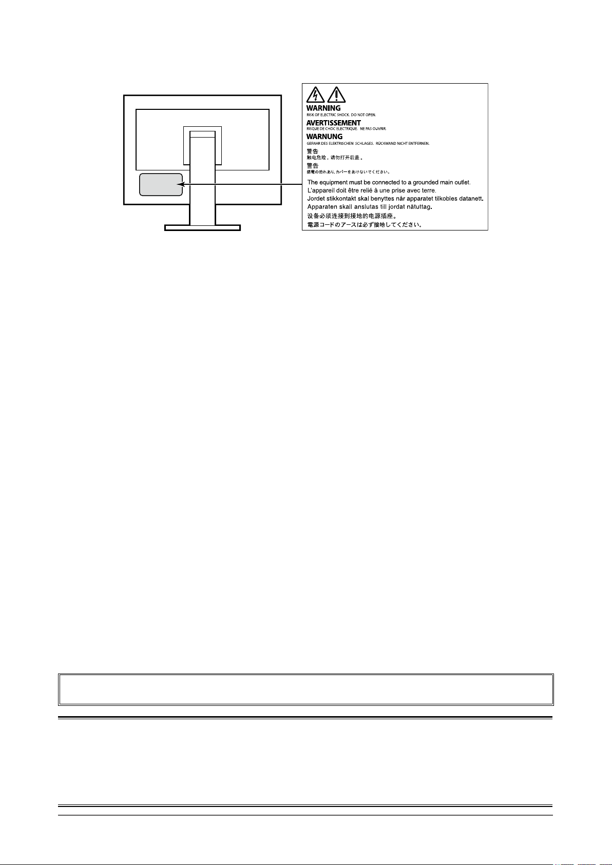
Location of Caution Statement
This product has been adjusted specically for use in the region to which it was originally shipped. If
operated outside this region, the product may not perform as stated in the specications.
No part of this manual may be reproduced, stored in a retrieval system, or transmitted, in any form or by
any means, electronic, mechanical, or otherwise, without the prior written permission of EIZO Corporation.
EIZO Corporation is under no obligation to hold any submitted material or information condential unless
prior arrangements are made pursuant to EIZO Corporation’s receipt of said information. Although every
effort has been made to ensure that this manual provides up-to-date information, please note that EIZO
monitor specications are subject to change without notice.
2
Page 3

Notice for this monitor
Aside from creating documents, viewing multimedia content, and other general purposes, this product is also
suited to applications such as creating CAD data and other drawings (Assuming usage of approximately 12
hours per day).
If using this product for the following kinds of applications, where an extremely high degree of reliability and
safety is required, then measures should be in place to maintain safety while using this product.
• Transportation equipment (ships, aircraft, trains, and automobiles)
• Safety devices (Disaster prevention systems, security control systems, etc.)
• Life-critical devices (medical devices, such as life-support devices and operating room devices)
• Nuclear energy control devices (Nuclear energy control systems, security control systems of nuclear facilities, etc.)
• Major system communication devices (operation control systems of transportation systems, air trafc control systems, etc.)
This product has been adjusted specically for use in the region to which it was originally shipped. If the
product is used outside the region, it may not operate as specied in the specications.
This product may not be covered by warranty for uses other than those described in this manual.
The specications noted in this manual are only applicable when the following are used:
• Power cords provided with the product
• Signal cables specied by us
Only use optional products manufactured or specied by us with this product.
If you place this product on a lacquer-coated desk, the color may adhere to the bottom of the stand due to
the composition of the rubber. Check the desk surface before use.
It takes about 30 minutes (under our measurement conditions) for the monitor display to stabilize. Please
wait 30 minutes or more after the monitor power has been turned on, and then adjust the monitor.
Monitors should be set to a lower brightness to reduce changes in luminosity caused by long-term use and
maintain a stable display.
When the screen image is changed after displaying the same image for extended periods of time, an
afterimage may appear. Use the screen saver or power save function to avoid displaying the same image for
extended periods of time. Depending on the image, an afterimage may appear even if it was displayed for
a short period of time. To remove such a phenomenon, change the image or keep the power turned off for
several hours.
If the monitor displays continuously over a long period of time, dark smudges or burn-in may appear. To
maximize the life of the monitor, we recommend the monitor be turned off periodically.
Periodic cleaning is recommended to keep the monitor looking new and to prolong its operation lifetime (refer
to “Cleaning” (page 4)).
The LCD panel is manufactured using high-precision technology. Although, missing pixels or lit pixels may
appear on the LCD panel, this is not a malfunction. Percentage of effective dots: 99.9994 % or higher.
The backlight of the LCD panel has a xed lifetime. Depending on the usage pattern, such as usage for
long continuous periods, the lifespan of the backlight may run out sooner, requiring replacement. When the
screen becomes dark or begins to icker, please contact your local EIZO representative.
Do not press on the LCD panel or edge of the frame strongly, as this may result in display malfunctions, such
as interference patterns, etc. If pressure is continuously applied to the LCD panel surface, the liquid crystal
may deteriorate or the LCD panel may be damaged. (If the pressure marks remain on the panel, leave the
monitor with a black or white screen. The symptom may disappear.)
Notice for this monitor
3
Page 4
Do not scratch or press on the LCD panel with any sharp objects, at this may result in damage to the LCD
panel. Do not attempt to brush with tissues as this may scratch the panel.
When the monitor is cold and brought into a room or the room temperature goes up quickly, dew
condensation may occur on the interior and exterior surfaces of the monitor. In that case, do not turn the
monitor on. Instead wait until the dew condensation disappears, otherwise it may cause some damage to the
monitor.
Cleaning
The stains on the cabinet and LCD panel surface can be removed by moistening part of a soft cloth with water.
Attention
• Chemicals such as alcohol and antiseptic solution may cause gloss variation, tarnishing, and fading of the cabinet
or LCD panel, and also quality deterioration of the image.
• Never use thinner, benzine, wax, or abrasive cleaner as they may damage the cabinet or LCD panel surface.
Note
• It is recommended that ScreenCleaner (available as an option) be used to clean the cabinet and LCD panel surface.
To use the monitor comfortably
• An excessively dark or bright screen may affect your eyes. Adjust the brightness of the monitor
according to the environmental conditions.
• Staring at the monitor for a long time tires your eyes. Take a 10-minute rest every hour.
Notice for this monitor
4
Page 5

CONTENTS
Notice for this monitor ......................................... 3
Cleaning .................................................................... 4
To use the monitor comfortably ............................. 4
CONTENTS ............................................................. 5
Chapter 1 Introduction ....................................... 6
1-1. Features ......................................................... 6
Support for DisplayPort over USB Type-C
●
(DP Alt Mode) / USB Power Delivery
High Degree of Flexibility for Installation ........ 7
●
Reduction of Power Consumption .................. 7
●
Realizing More Convenient Operations
●
Using Screen InStyle ...................................... 7
1-2. Controls and Functions ............................... 8
Front ................................................................ 8
●
Rear ................................................................. 9
●
1-3. Supported Resolutions ...............................10
For DisplayPort ..............................................10
●
For HDMI ........................................................11
●
For USB-C ......................................................12
●
1-4.
Changing the Computer Display Settings
Windows 10 ....................................................13
●
Windows 8.1 / Windows 7 ..............................13
●
macOS ...........................................................13
●
Chapter 2 Basic Adjustment / Setting ............ 14
2-1. Switch Operation Method ...........................14
2-2. Switching Input Signals ..............................15
PbyP display ...................................................15
●
PinP display ....................................................17
●
2-3.
Switching Display Modes (Color Modes)
Display Modes ................................................18
●
2-4. Conserving Energy ......................................19
2-5. Adjusting Brightness ..................................21
2-6. Adjusting Volume.........................................21
Chapter 3 Advanced Adjustment / Setting .... 22
3-1. Basic Operation of the Setting Menu ....... 22
3-2. Setting Menu Functions ............................. 23
Color Adjustment ........................................... 23
●
Signal Settings .............................................. 26
●
Preference Settings ...................................... 28
●
Language ...................................................... 29
●
Information .................................................... 30
●
Chapter 4 Administrator Settings ................... 31
4-1. Basic Operation of the “Administrator
Settings” Menu .............................................31
4-2. Functions of the “Administrator
Settings” Menu ............................................ 32
................ 6
...13
...18
Chapter 5 Troubleshooting .............................. 34
5-1. No Picture .................................................... 34
5-2. Imaging Problems ....................................... 35
5-3. Other Problems ........................................... 36
Chapter 6 Reference ........................................ 37
6-1. Attaching the Optional Arm ........................37
Attaching the optional arm
●
(or optional stand) ......................................... 38
Attaching the original stand .......................... 38
●
6-2. Detaching/Attaching the Cable Holder ..... 39
Detaching the cable holder ........................... 39
●
Attaching the cable holder ............................ 39
●
6-3. Detaching / Attaching the Cable Cover .... 40
Attaching the cable cover .............................. 40
●
Detaching the cable cover .............................41
●
6-4. Connecting Multiple PCs ........................... 42
Connection examples ....................................42
●
6-5. Using the USB Hub Function ..................... 43
Connection procedure................................... 43
●
6-6. Specications ............................................. 44
Accessories ................................................... 45
●
Appendix .............................................................. 46
Trademark ............................................................... 46
License .................................................................... 46
ENERGY STAR ........................................................ 46
FCC Declaration of Conformity .............................47
CONTENTS
5
Page 6
Chapter 1 Introduction
Thank you very much for choosing an EIZO color LCD monitor.
1-1. Features
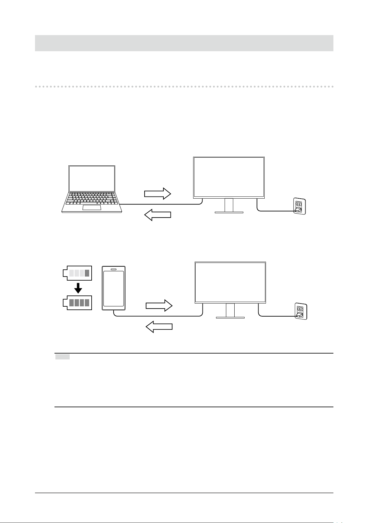
Support for DisplayPort over USB Type-C (DP Alt Mode) / USB Power
●
Delivery
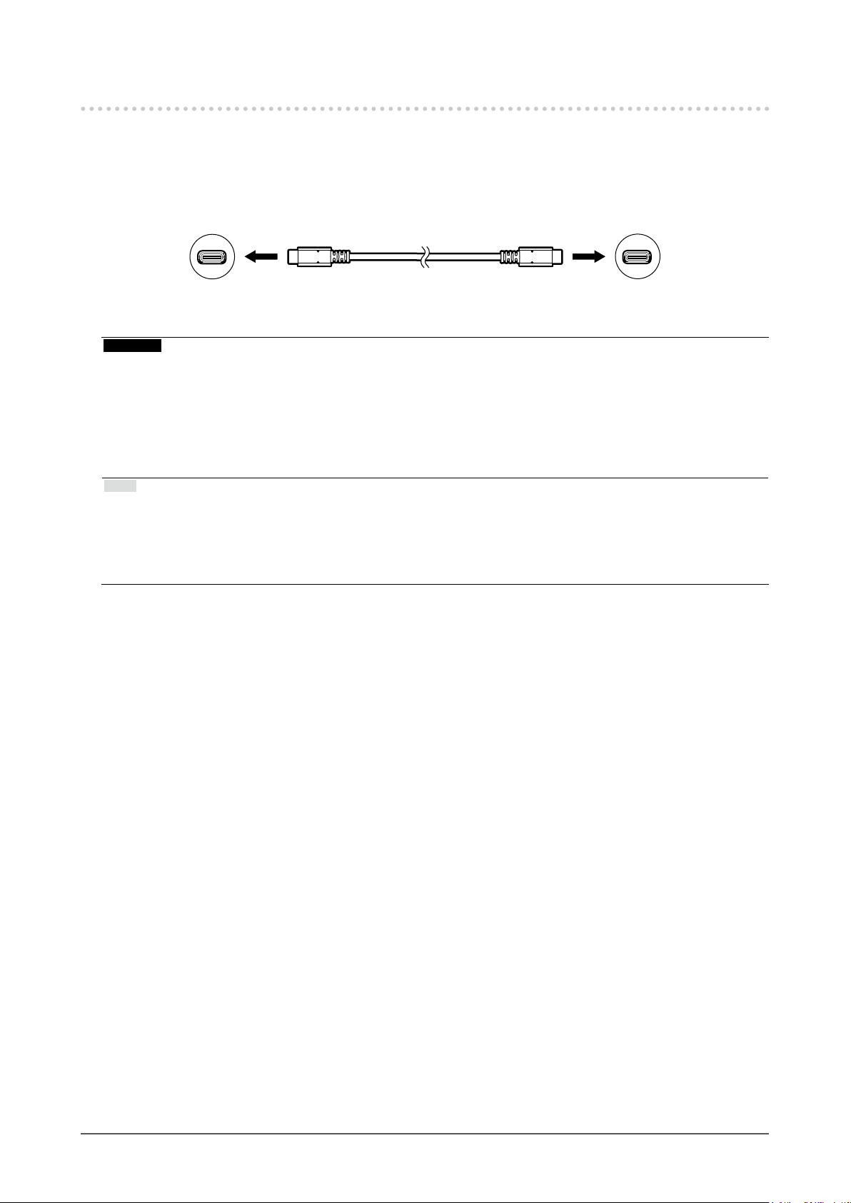
This product is equipped with a USB Type-C (USB-C) connector compatible with DP Alt Mode and
USB Power Delivery.
• While being used as an external monitor of a notebook PC, this product can supply power to the
PC.
Video Signals
Power Supply
• While displaying photos and motion pictures from a smartphone or tablet, this product can charge
the device.
Video Signals
100%
Power Supply
Note
• Devices to be connected must be equipped with a USB-C connector, and support the charging function
based on USB-C or USB Power Delivery.
• The device connected to the monitor can be charged even when the monitor is in power saving mode.
• Even when the monitor is turned off with the main power turned on, the connected device can be recharged.
In this case, the “Compatibility Mode” needs to be left “On”. For details about how to modify the settings,
please refer to “4-1. Basic Operation of the “Administrator Settings” Menu” (page 31).
Chapter 1 Introduction
6
Page 7
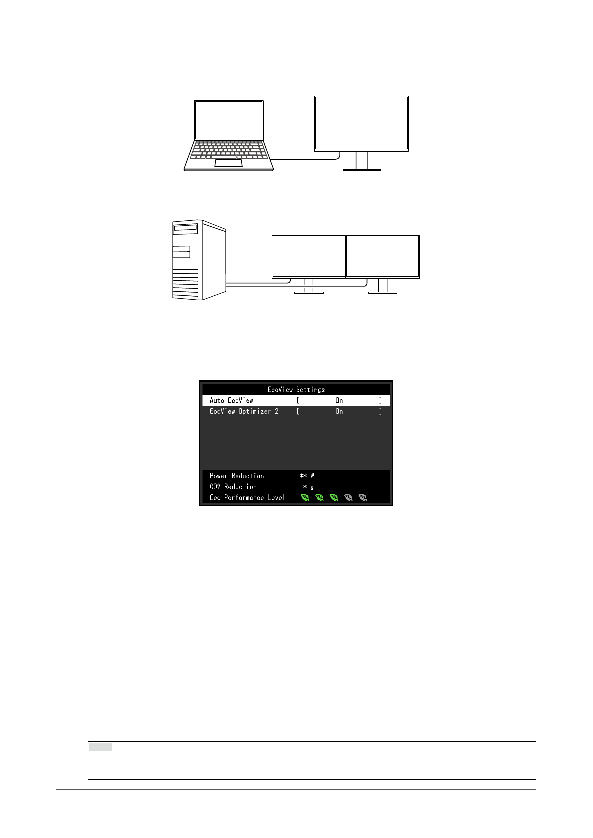
High Degree of Flexibility for Installation
●
• This product can be used as an external monitor of a notebook computer.
• This product can be used in a multi-monitor conguration in which multiple monitors are connected
to a single PC.
Reduction of Power Consumption
●
This product provides a function that automatically adjusts the screen brightness to reduce power
consumption *1. Power Reduction, CO2 Reduction, and Eco Performance Level can be checked on
the "EcoView Settings" menu. (page 19)
• Auto EcoView
The ambient light sensor on the front of the monitor detects the ambient brightness to automatically
adjust the screen brightness to a comfortable level.
• EcoView Optimizer 2
The monitor automatically adjusts the screen brightness according to the white level of the input
signal. This function can reduce power consumption while maintaining the brightness specied by
the input signal.
*1 Reference values
Maximum power consumption: 163 W (when a USB device is connected and the speakers are working),
standard power consumption: 32 W (brightness 120 cd/m
speakers are not working, at default settings)
Realizing More Convenient Operations Using Screen InStyle
●
The "Screen InStyle" monitor control utility enables you to use the monitor more conveniently.
• The monitor color mode can be switched automatically to suit the software to be used.
• When multiple monitors are installed, you can turn the power on and off or change the color mode
of all monitors at the same time.
Note
• Screen InStyle can be downloaded from our web site (http://www.eizoglobal.com).
• The Windows operating systems are only supported.
2
, when no USB device is connected and the
Chapter 1 Introduction
7
Page 8
1-2. Controls and Functions
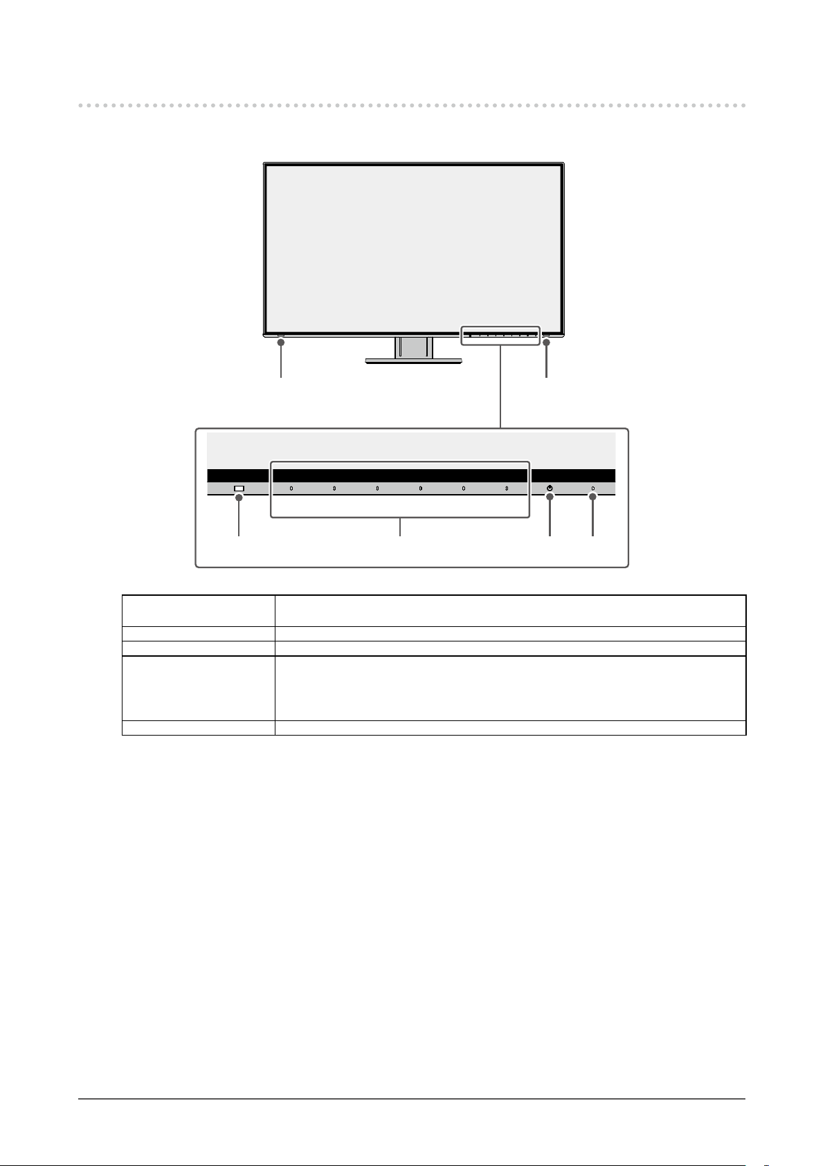
Front
●
5 5
4321
1. Ambient light sensor Detects ambient brightness. If you use Auto EcoView, the screen brightness is
automatically adjusted according to the ambient brightness (page 20).
2. Operation switches Displays menus. Operate the switches according to the operation guide (page 22).
3. Power switch Turns the power on or off.
4. Power indicator Indicates the monitor’s operation status.
White: Normal operation mode
Orange: Power saving mode
OFF: Main power / power off
5. Speakers Outputs audio.
Chapter 1 Introduction
8
Page 9
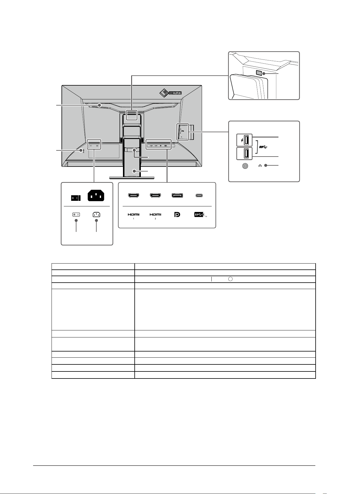
Rear
●
6
11
12
7
15
16
10
8 9
6. Handle This handle is used for transportation.
7. Security lock slot Complies with Kensington’s MicroSaver security system.
8. Main power switch
9. Power connector Connects the power cord.
10. Input signal connectors The following connectors are available on the monitor rear in order of left to
11. Lock button Use this button to remove the monitor from the stand.
12. USB downstream port
(support for boost charging)
13. USB downstream port Connects to a peripheral USB device.
14. Headphone jack Connects to headphones.
15. Cable holder Holds the monitor cables.
16. Stand
*1 An optional arm (or optional stand) can be attached by removing the stand section (see “6-1. Attaching the
*1
Optional Arm” (page 37)).
Turns the main power on or off.
right.
HDMI connector (1)
HDMI connector (2)
DisplayPort connector
USB-C connector (USB upstream port)
Connects to a peripheral USB device. (page 28)
Adjusts the height and angle (tilt and swivel) of the monitor.
: On, : Off
13
14
Chapter 1 Introduction
9
Page 10
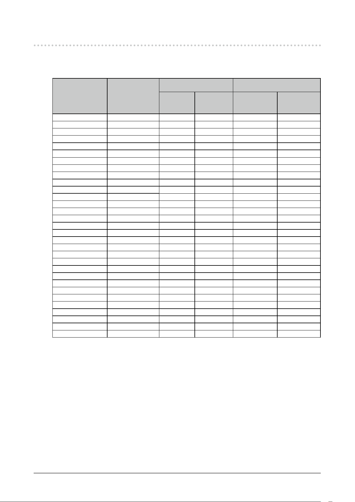
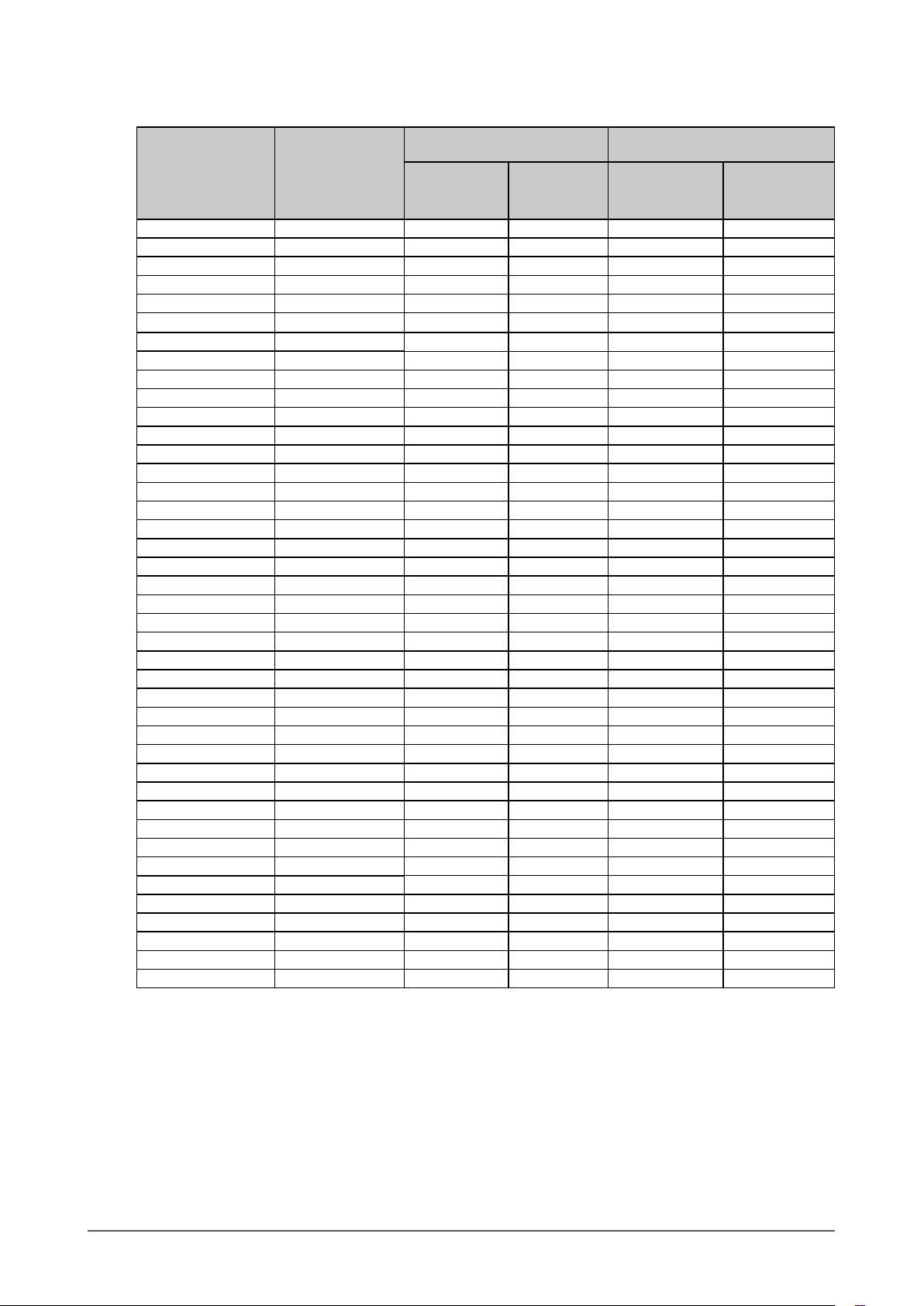
1-3. Supported Resolutions
The monitor supports the following resolutions.
For DisplayPort
●
Single screen and PinP
Resolution
720 × 400 70.087 √ √ √ √
640 × 480 59.940 √ √ √ √
640 × 480 60.000 √ √ √ √
800 × 600 60.317 √ √ √ √
1024 × 768 60.004 √ √ √ √
1280 × 720 59.855 √ √ √ √
1280 × 720 59.979 √ √ √ √
1280 × 800 59.810 √ √ √ √
1280 × 800 59.910 √ √ √ √
1280 × 1024 60.020 √ √ √ √
1600 × 900 60.000 √ √ √ √
1600 × 1200 60.000 √ √ √ √
1680 × 1050 59.954 √ √ √ √
1680 × 1050 59.883 √ √ √ √
1920 × 1200 59.885 √ √ √ 1920 × 1200 59.950 √ √ √ 2560 × 1440 59.951 √ √ - 1280 × 1600 59.910 - - √ 3840 × 2160 59.997 √
3840 × 2160 29.981 √ √
1920 × 2160 59.988 - - √
1280 × 720 60.000 √ √ √ √
1280 × 720 59.940 √ √ √ √
1920 × 1080 60.000 √ √ √ √
1920 × 1080 59.940 √ √ √ √
1920 × 1080 30.000 √ √ √ √
1920 × 1080 29.970 √ √ √ √
720 × 480 60.000 √ √ √ √
720 × 480 59.940 √ √ √ √
720 × 480 60.000 √ √ √ √
720 × 480 59.940 √ √ √ √
*1 Supported signals differ depending on the settings in “Administrator Settings”. For information on how to
change the settings, see “4-2. Functions of the “Administrator Settings” Menu” (page 32).
*2 This is the recommended resolution.
Vertical scan
frequency (Hz)
Version 1.2 Version 1.1
display
*2
*1
Dual screen
- - -
*2
PbyP display
display
- -
*2
Quad screen
display
-
Chapter 1 Introduction
10
Page 11
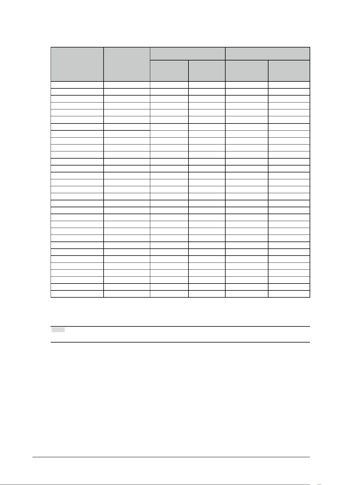
For HDMI
●
Single screen and PinP
Resolution
720 × 400 70.087 √ √ √ √
640 × 480 59.940 √ √ √ √
640 × 480 60.000 √ √ √ √
800 × 600 6 0.317 √ √ √ √
1024 × 768 60.004 √ √ √ √
1280 × 720 59.855 √ √ √ √
1280 × 720 59.979 √ √ √ √
1280 × 800 59.810 √ √ √ √
1280 × 800 59.910 √ √ √ √
1280 × 1024 60.020 √ √ √ √
1600 × 900 60.000 √ √ √ √
1600 × 1200 60.000 √ √ √ √
1680 × 1050 59.954 √ √ √ √
1680 × 1050 59.883 √ √ √ √
1920 × 1200 59.885 √ √ √ 1920 × 1200 59.950 √ √ √ 2560 × 1440 59.951 √ √ - 1280 × 1600 59.910 - - √ 3840 × 2160 59.997 √ - - 3840 × 2160 29.981 √ √ - 1920 × 2160 59.988 - - √
1920 × 2160 29.952 - - √ -
1280 × 720 60.000 √ √ √ √
1280 × 720 59.940 √ √ √ √
1280 × 720
1920 × 1080 60.000 √ √ √ √
1920 × 1080 59.940 √ √ √ √
1920 × 1080
1920 × 1080 30.000 √ √ √ √
1920 × 1080 29.970 √ √ √ √
720 × 480 60.000 √ √ √ √
720 × 480 59.940 √ √ √ √
720 × 480 60.000 √ √ √ √
720 × 480 59.940 √ √ √ √
720 × 576 50.000 √ √ √ √
720 × 576 50.000 √ √ √ √
3840 × 2160 60.000 √
3840 × 2160 59.940 √
3840 × 2160 50.000 √ - - -
3840 × 2160 30.000 √ √
3840 × 2160 29.970 √ √
*1 Supported signals differ depending on the settings in “Administrator Settings”. For information on how to
change the settings, see “4-2. Functions of the “Administrator Settings” Menu” (page 32).
*2 This is the recommended resolution.
Vertical scan
frequency (Hz)
50.000
50.000
4K UHD 60Hz 4K UHD 30Hz
display
√ √ √ √
√ √ √ √
*2
*2
*1
Dual screen
- - -
- - -
*2
*2
PbyP display
display
*2
- -
- -
Quad screen
display
-
Chapter 1 Introduction
11
Page 12
For USB-C
●
Single screen and PinP
Resolution
720 × 400 70.087 √ √ √ √
640 × 480 59.940 √ √ √ √
640 × 480 60.000 √ √ √ √
800 × 600 6 0.317 √ √ √ √
1024 × 768 60.004 √ √ √ √
1280 × 720 59.855 √ √ √ √
1280 × 720 59.979 √ √ √ √
1280 × 800 59.810 √ √ √ √
1280 × 800 59.910 √ √ √ √
1280 × 1024 60.020 √ √ √ √
1600 × 900 60.000 √ √ √ √
1600 × 1200 60.000 √ √ √ √
1680 × 1050 59.954 √ √ √ √
1680 × 1050 59.883 √ √ √ √
1920 × 1200 59.885 √ √ √ 1920 × 1200 59.950 √ √ √ 2560 × 1440 59.951 √ √ - 1280 × 1600 59.910 - - √ 3840 × 2160 59.997 √
3840 × 2160 29.981 √ √
1920 × 2160 59.988 - - √
1280 × 720 60.000 √ √ √ √
1280 × 720 59.940 √ √ √ √
1920 × 1080 60.000 √ √ √ √
1920 × 1080 59.940 √ √ √ √
1920 × 1080 30.000 √ √ √ √
1920 × 1080 29.970 √ √ √ √
720 × 480 60.000 √ √ √ √
720 × 480 59.940 √ √ √ √
720 × 480 60.000 √ √ √ √
720 × 480 59.940 √ √ √ √
*1 Supported signals differ depending on the settings in “Administrator Settings”. For information on how to
change the settings, see “4-2. Functions of the “Administrator Settings” Menu” (page 32).
*2 This is the recommended resolution.
Vertical scan
frequency (Hz)
4K UHD 60Hz
/ USB2.0
display
*2
*1
4K UHD 30Hz
/ USB3.1
- - -
*2
Dual screen
PbyP display
display
- -
*2
Quad screen
display
-
Note
• Only the progressive scan type is supported.
Chapter 1 Introduction
12
Page 13

1-4. Changing the Computer Display Settings
If the image is not displayed properly after connecting the monitor to a PC, follow the procedure below to
change the display settings on the computer.
Windows 10
●
1. Right-click the mouse anywhere on the desktop except on icons. A menu is displayed.
2. From the displayed menu, click “Display Settings”. The “Settings” screen is displayed.
3. If multiple monitors, including notebook PC screens, are connected to the computer, select “Extend
these displays” in the “Multiple displays” menu, and then click “Keep changes” on the conrmation
screen. After changing the settings, select a monitor in the “Select and rearrange displays” menu.
4. Select the “Make this my main display” option in the “Multiple displays” menu. This enables the
monitor to display images properly.
5. Conrm that the recommended resolution for the monitor is set in the “Resolution” menu.
(“(Recommended)” is displayed after the resolution.)
6. To change the size of text and icons, select a magnication in the menu of zoom percentages
according to personal preference.
7. If a message prompting you to sign out is displayed after changing the settings, sign out and then
sign in again.
Windows 8.1 / Windows 7
●
* For Windows 8.1, click the "Desktop" tile on the Start Screen to display the desktop.
1. Right-click the mouse anywhere on the desktop except on icons. A menu is displayed.
2. From the displayed menu, click “Screen resolution”. The settings screen is displayed.
3. If multiple monitors, including notebook PC screens, are connected to the computer, select “Extend
these displays” in the “Multiple displays” menu, and then click “Apply”. Click “Keep changes” on
the conrmation screen.
4. Select a monitor in the “Display” menu, and then select the “Make this my main display” option
and click “Apply”. This enables the monitor to display images properly.
5. Conrm that the recommended resolution for the monitor is set in the “Resolution” menu.
(“(recommended)” is displayed after the resolution.)
6. To change the size of text and icons, click “Make text and other items larger or smaller”, select a
size according to personal preference on the settings screen, and then click “Apply”.
7. If a message prompting you to sign out/log off is displayed after changing the settings, sign out/
log off and then sign in/log in again.
macOS
●
1. Select “System Preferences” from the Apple menu.
2. When the “System Preferences” panel is displayed, click “Displays”.
3. If multiple monitors, including notebook PC screens, are connected to the computer, make sure
that “Mirror Displays” is not selected on the “Arrangement” tab. If it is selected, remove the check
mark.
4. Select the “Display” tab, and make sure that “Default for display” is selected for “Resolution”. If
it is not selected, add a check mark. The correct resolution has now been set for your display.
Close the “System Preferences” panel. If multiple monitors, including notebook PC screens, are
connected to the computer, congure these settings in “Display” on each monitor.
5. To select a resolution according to personal preference, select “Scaled” and then select a
resolution (either from a list or icons), and then close the panel.
Chapter 1 Introduction
13
Page 14
Chapter 2 Basic Adjustment / Setting
This product enables users to change the brightness according to personal preference or to suit the usage
environment and reduce power consumption to conserve energy.
This chapter describes the basic functions that can be adjusted and set using the switches on the front of the
monitor.
For advanced adjustment and setting procedures using the Setting menu, see “Chapter 3 Advanced
Adjustment / Setting” (page 22).
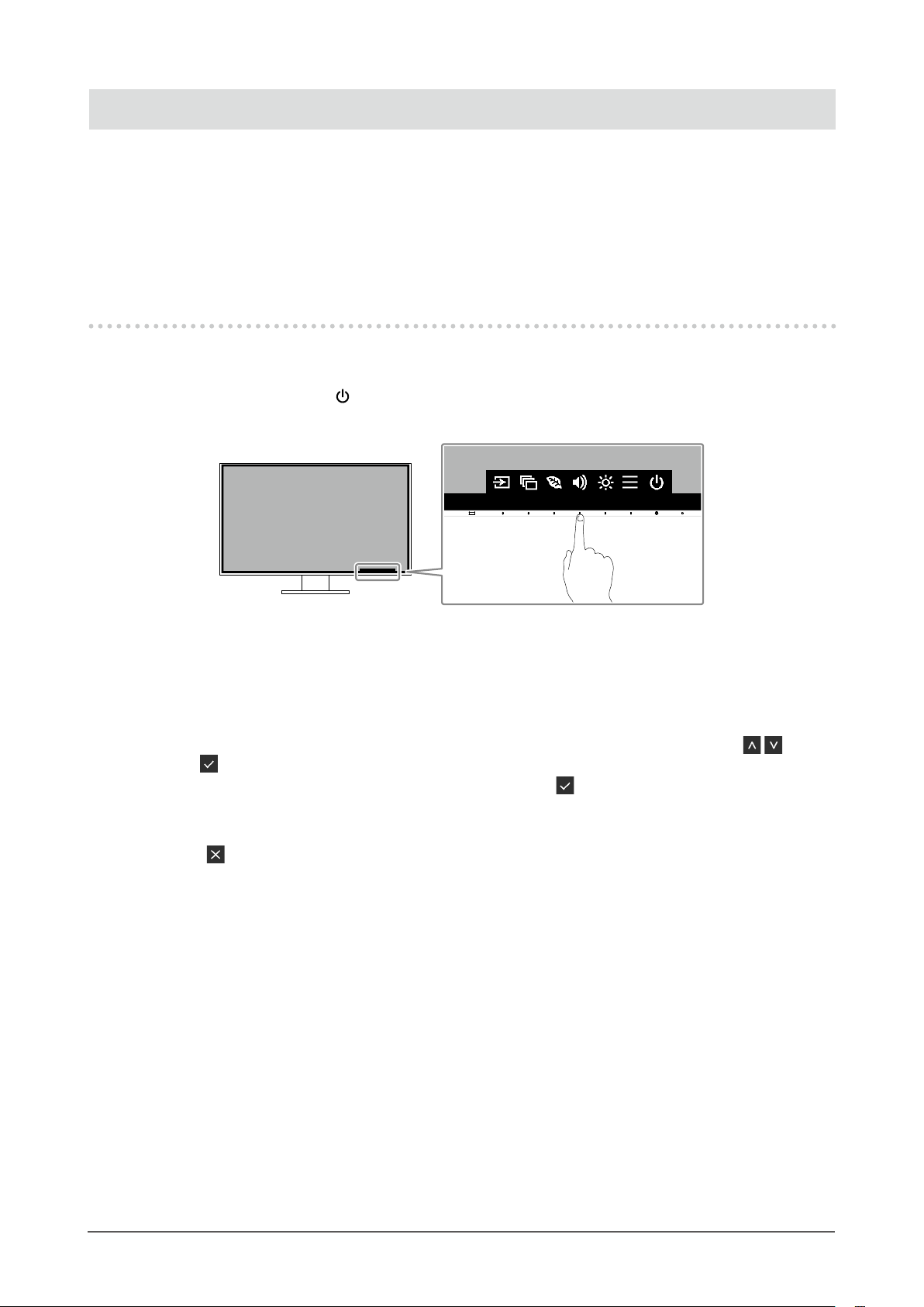
2-1. Switch Operation Method
Displaying the operation guide
1.
1. Touch any switch (except ).
The operation guide appears on the screen.
Adjusting / setting
2.
1. Touch a switch for adjustment / setting.
The Adjustment / Setting menu appears.
(A submenu may also be displayed. In this case, select the item for adjustment / setting using
select
2. Perform adjustment / setting with the switches and select to accept the changes.
Exiting
3.
1. Select to exit the menu.
.)
and
Chapter 2 Basic Adjustment / Setting
14
Page 15
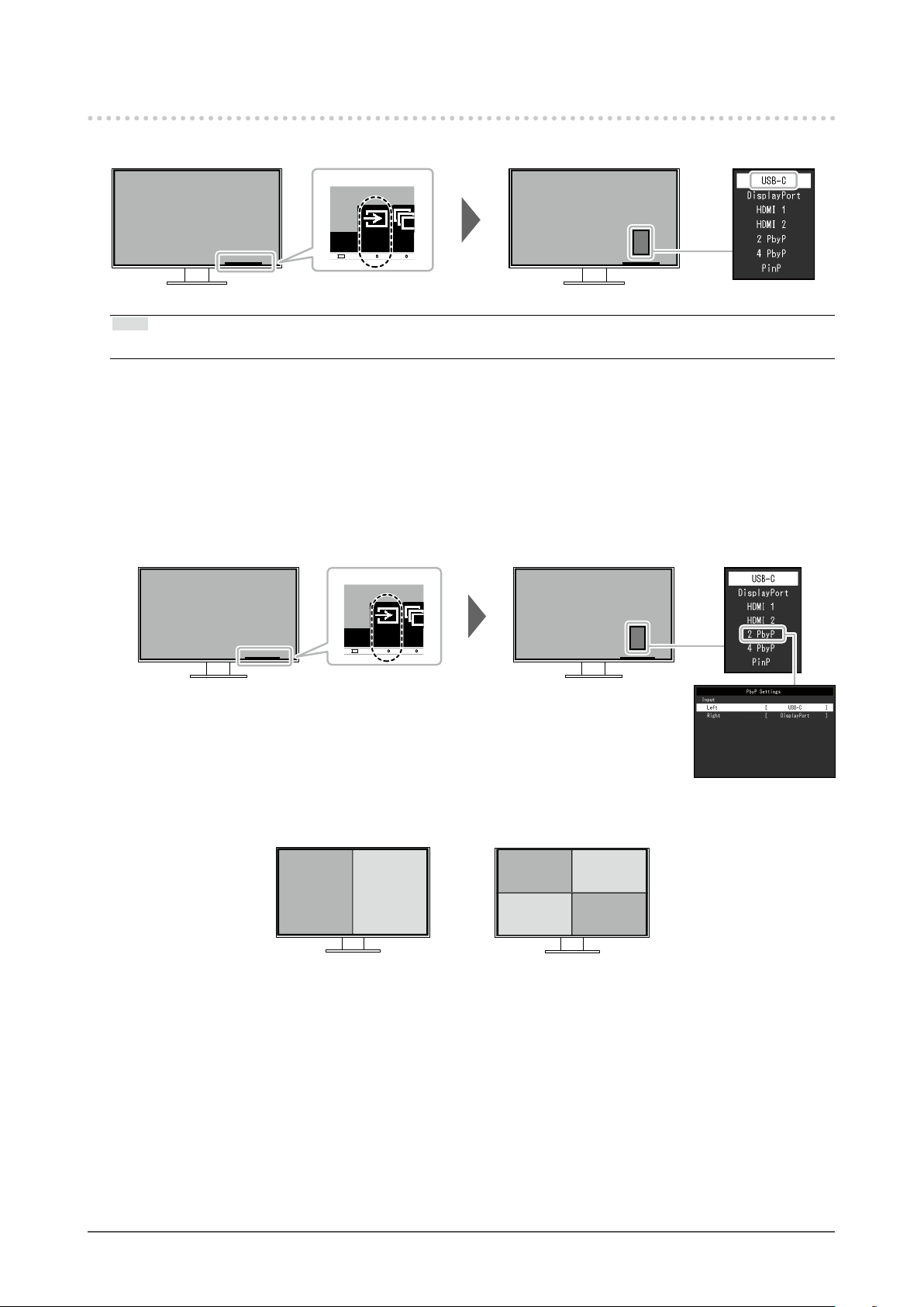
2-2. Switching Input Signals
When a monitor has multiple signal inputs, the signal to display on-screen can be changed.
Note
• "Screen InStyle" allows you to switch input signals using the shortcut keys on the keyboard.
PbyP display
●
By selecting PbyP (Picture by Picture) display when a monitor has multiple input signals, windows can
be displayed side-by-side (dual screen) or side-by-side and above-and-below (quad screen).
Because multiple windows can be displayed on a single monitor, the need for changing between
signals is eliminated, which leads to increased work efciency.
By selecting PbyP display, the combination of signals to display on the left and right windows or quad
screen can be switched.
PbyP display image (dual screen)
A B
PbyP display image (quad screen)
A
B
C
D
Chapter 2 Basic Adjustment / Setting
15
Page 16

PbyP
Settings
Function
Input Left USB-C
Right USB-C
Upper Left USB-C
Lower Left USB-C
Upper Right USB-C
Lower Right USB-C
Setting
Value
DisplayPort
HDMI 1
HDMI 2
DisplayPort
HDMI 1
HDMI 2
DisplayPort
HDMI 1
HDMI 2
DisplayPort
HDMI 1
HDMI 2
DisplayPort
HDMI 1
HDMI 2
DisplayPort
HDMI 1
HDMI 2
Description
Select an input signal to be displayed on the left screen of
the PbyP display (dual screen).
Select an input signal to be displayed on the right screen
of the PbyP display (dual screen).
Select an input signal to be displayed on the upper left
screen of the PbyP display (quad screen).
Select an input signal to be displayed on the lower left
screen of the PbyP display (quad screen).
Select an input signal to be displayed on the upper right
screen of the PbyP display (quad screen).
Select an input signal to be displayed on the lower right
screen of the PbyP display (quad screen).
Note
• You cannot set the same input signal for multiple screens. Therefore, when changing the input signal for a
screen, if you select an input signal that has already been set for another screen, the signals are switched
automatically.
Chapter 2 Basic Adjustment / Setting
16
Page 17

PinP display
●
By selecting PinP (Picture in Picture) display when a monitor has multiple input signals, a large
window and a small window can be displayed.
Because multiple windows can be displayed on a single monitor, the need for changing between
signals is eliminated, which leads to increased work efciency.
By selecting PinP display, the combination of the signals to display on the large and small windows
can be switched.
PinP display image
Large window
PinP
Settings
Function
PinP Size Large
PinP Position Upper Left
Input Large Window USB-C
Small Window USB-C
Setting
Value
Small
Lower Left
Upper Right
Lower Right
DisplayPort
HDMI 1
HDMI 2
DisplayPort
HDMI 1
HDMI 2
A
B
Select the size of the small window.
Select the position of the small window.
Select the input signal for the large window.
Select the input signal for the small window.
Small window
Description
Note
• You cannot set the same input signal for the large and small windows. Therefore, when changing the input
signal for the large window, if you select the input signal that has already been set for the small window, the
input signals for the large and small windows are switched automatically.
Chapter 2 Basic Adjustment / Setting
17
Page 18
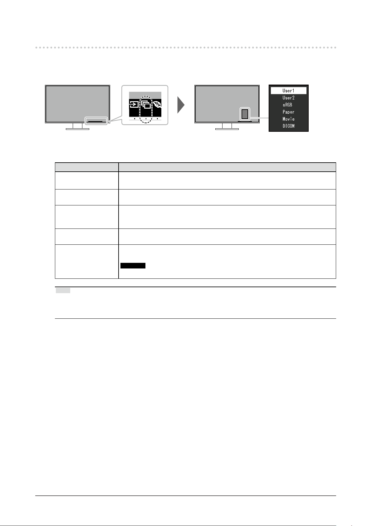
2-3. Switching Display Modes (Color Modes)
This product is preinstalled with color modes for various display purposes.
By switching the mode according to the purpose and contents of the display, you can display images in
an appropriate manner.
Display Modes
●
Color Mode Purpose
User1
User2
sRGB
Paper
Movie
DICOM
Select either of these modes to set a user-dened display mode.
This mode is suitable for matching color reproduction with peripheral devices that
support sRGB, such as when printing photos taken using a digital camera.
This mode uses color tones and contrast similar to that of paper to produce a printed
paper effect. It is suitable for displaying images from media such as books and
documents.
This mode displays moving images brightly and with a clear-cut three-dimensional
appearance. It is suitable for playing back video content.
Select this mode to simply display medical purpose digital images based on DICOM
Part 14.
Attention
• This is not intended to be used for diagnostic purposes.
Note
• "Screen InStyle" allows you to select the color mode automatically according to the software in use.
• In Paper mode, the amount of blue light emitted from the screen is reduced by changing the color tone and
controlling the brightness.
Chapter 2 Basic Adjustment / Setting
18
Page 19

2-4. Conserving Energy
This monitor is equipped with EcoView functions to enable users to conserve energy.
You can use this function to curtail unnecessary power consumption and save on electricity expenses.
Saving power also reduces carbon dioxide emissions.
Note
• The power saving level (Power Reduction, CO2 Reduction, and Eco Performance Level) can be checked on the
“EcoView Settings” menu. The more indicators that light up representing the Eco Performance Level, the higher
the power saving level attained.
- Power Reduction: the reduction in the backlight’s power consumption as a result of the adjusted brightness
value.
- CO
Reduction: converted from the “Power Reduction” value, this is an estimate of the quantity of CO2
2
emissions reduced when using the monitor for 1 hour.
• The numeric value is a result of calculation based on a default setting (0.000555t-CO2 / kWh) determined by a
Japanese ministerial ordinance (2006, Ministry of Economy, Trade and Industry, Ministry of Environment, civil
code article 3) and may differ depending on country and year.
Chapter 2 Basic Adjustment / Setting
19
Page 20

Function
Auto EcoView
EcoView Optimizer 2
Setting
Value
On
Off
On
Off
Description
The ambient light sensor on the front of the monitor
detects the ambient brightness to automatically adjust
the screen brightness to a comfortable level using Auto
EcoView. The power consumption of the backlight can
be curtailed by adjusting the brightness to an appropriate
level.
This function can also mitigate eye strain and tiredness
caused by a screen that is too bright or too dark.
Note
• Be careful not to block the ambient light sensor on the
lower side of the monitor when using Auto EcoView.
• Even when the Auto EcoView setting is “On”, the
operation switch on the front of the monitor or color
adjustment can be used to change the “Brightness”
to suit your personal preference. Moreover, the
manner in which the Auto EcoView function changes
brightness also differs according to the changed
value.
• When “DICOM” is selected for the color mode, the
Auto EcoView setting is turned “Off”.
The monitor automatically adjusts the screen brightness
according to the white level of the input signal.
This function can reduce power consumption while
maintaining the brightness specied by the input signal.
Note
• The setting is turned “Off” in the following cases:
- When “Movie” or “DICOM” is selected for the color
mode
- During PbyP/PinP display
• When set to “On”, the appearance of pale colors may
change. If this bothers you, set this function to “Off”.
Chapter 2 Basic Adjustment / Setting
20
Page 21

2-5. Adjusting Brightness
The brightness of the screen can be adjusted to suit the installation environment or personal preference.
The screen brightness is adjusted by changing the brightness of the backlight (light source from the LCD
back panel).
Setting Value
0 to 100
2-6. Adjusting Volume
The volume of the speakers and headphones can be set individually.
Setting Value
0 to 30
When the speakers are
connected
When the headphones are
connected
Chapter 2 Basic Adjustment / Setting
21
Page 22

Chapter 3 Advanced Adjustment / Setting
This chapter describes the advanced monitor adjustment and setting procedures using the Setting menu.
For basic functions, see “Chapter 2 Basic Adjustment / Setting” (page 14).
3-1. Basic Operation of the Setting Menu
Menu display
1.
1. Touch any switch (except ).
The operation guide appears.
2. Select .
The Setting menu appears.
Adjusting / setting
2.
1. Select a menu to adjust / set with and select .
The Sub menu appears.
2. Select an item to adjust / set with and select .
The Adjustment / Setting menu appears.
3. Perform adjustment / setting with or and select to accept the changes.
The Sub menu appears.
Selecting
making changes.
Exiting
3.
1. Selecting several times will terminate the Setting menu.
Chapter 3 Advanced Adjustment / Setting
22
during adjustment / setting will cancel the adjustment / setting and restore the state prior to
Page 23

3-2. Setting Menu Functions
Color Adjustment
●
The color mode setting status can be adjusted according to personal preference.
Functions that can be adjusted differ depending on the color mode.
Function
Brightness
Contrast
Temperature
Gamma
Super Resolution
Advanced
Settings
Reset
Overdrive
Hue
Saturation
Gain
User1
User2
√ √ √ √
√
√
√
√
√
√
√
√
√ √ √ √
√: Adjustable -: Not adjustable
Color Mode
sRGB Paper Movie DICOM
-
- -
-
- - - -
-
- - - -
- -
- -
- - - -
√ √
√ √
√
√
√
-
-
-
-
-
-
Attention
• It takes about 30 minutes for the monitor display to stabilize. Please wait 30 minutes or more after power to
the monitor has been turned on before adjusting the monitor.
• The same image may be observed in different colors on multiple monitors due to monitor-specic
characteristics. Make ne color adjustments visually when matching colors across multiple monitors.
Chapter 3 Advanced Adjustment / Setting
23
Page 24

Function
Color Mode User1
Brightness 0 to 100
Contrast 0 to 100
Temperature Off
Gamma 1.8
Super Resolution Standard
Setting
Value
User2
sRGB
Paper
Movie
DICOM
4000 K to
10000 K
increments of
500 K. 9300 K
is included.)
2.0
2.2
2.4
Low
Off
Description
Select the desired mode according to the monitor application.
The color setting status can also be adjusted according to personal
preference. Select the mode for adjustment and perform adjustment
using the relevant functions.
Note
• For details on the adjustment status of each mode, see “2-3.
Switching Display Modes (Color Modes)” (page 18).
The screen brightness is adjusted by changing the brightness of the
backlight (light source from the LCD back panel).
Note
• If the image is too dark even when the brightness is set to 100,
adjust the contrast.
The brightness of the screen is adjusted by varying the video signal
level.
Note
• A contrast of 50 displays every color gradation.
• When adjusting the monitor, it is recommended to perform
brightness adjustment, which does not lose gradation
characteristics, prior to contrast adjustment.
• Perform contrast adjustment in the following cases.
- If the image is too dark even when the brightness is set to 100
(Set the contrast to higher than 50.)
Adjust the color temperature.
The color temperature is normally used to express the hue of “White”
and/or “Black” with a numerical value. The value is expressed in
(in
degrees “K” (Kelvin).
The screen becomes reddish at low color temperatures and bluish at
high color temperatures, similar to the temperatures of a ame. A gain
preset value is set for each color temperature setting value.
Note
• The value shown in “K” is available only as a reference.
• “Gain” allows you to perform more advanced adjustment.
• If set to “Off”, the image is displayed in the preset color of the
monitor (Gain: 100 for each RGB channel).
• When the gain is changed, the color temperature setting changes
to “Off”.
Adjust the gamma.
While the brightness of the monitor varies depending on the input
signal, the variation rate is not proportional to the input signal.
Maintaining the balance between the input signal and brightness of
the monitor is referred to as “Gamma correction”.
Note
• If "sRGB" is selected for the color mode, the gamma value is
xed to "sRGB".
• If “Paper” is selected for the color mode, “Paper” is displayed for
the gamma value.
• If “DICOM” is selected for the color mode, “DICOM” is displayed
for the gamma value.
Image blur can be reduced by enhancing its outline.
Chapter 3 Advanced Adjustment / Setting
24
Page 25

Function
Advanced
Settings
Reset - Reset any color adjustments for the currently selected color mode
Overdrive Enhanced
Hue -50 to 50
Saturation
Gain 0 to 100
Setting
Value
This function allows you to set the overdrive intensity based on the
Standard
Off
-50 to 50 Adjust the color saturation.
use of the monitor.
Image lag can be reduced by using the “Enhanced” setting when
displaying moving images.
Adjust the hue.
Note
• Using this function may prevent some color gradations from being
able to be displayed.
Note
• Using this function may prevent some color gradations from being
able to be displayed.
• The minimum value (-50) changes the screen to monochrome.
The brightness of each red, green, and blue color component is
referred to as “Gain”. The hue of “white” can be changed by adjusting
the gain.
Note
• Using this function may prevent some color gradations from being
able to be displayed.
• The gain value changes according to the color temperature.
• When the gain is changed, the color temperature setting changes
to “Off”.
back to the default settings.
Description
Chapter 3 Advanced Adjustment / Setting
25
Page 26
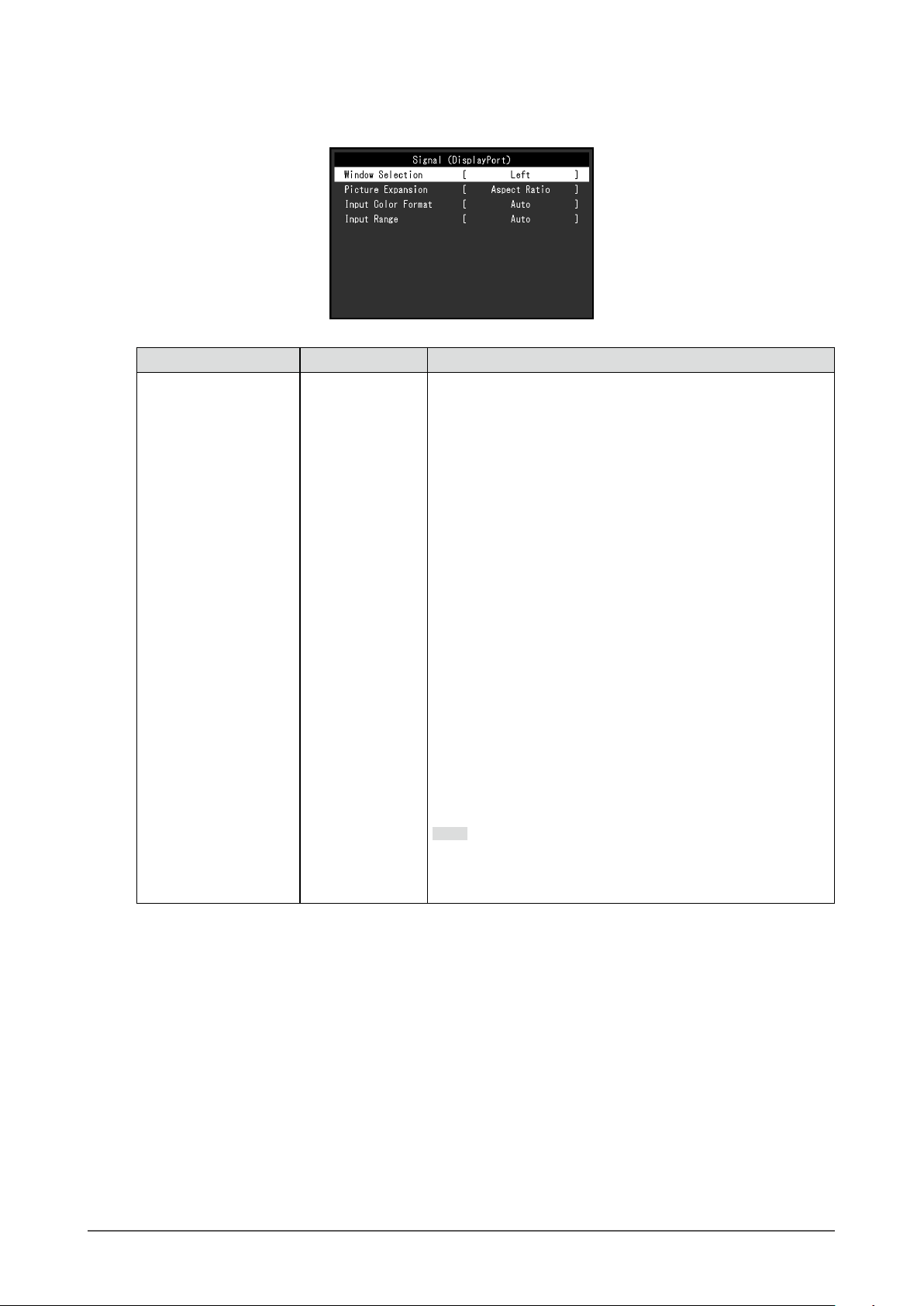
Signal Settings
●
Set the details regarding input signal, such as the screen display size and color format.
Function Setting Value Description
Window Selection Left
Right
Upper Left
Lower Left
Upper Right
Lower Right
Large Window
Small Window
Select the target for the signal settings.
When using PbyP/PinP display, select this target rst.
• “Left”
The setting is applied to the left screen in PbyP display (dual
screen).
• “Right”
The setting is applied to the right screen in PbyP display
(dual screen).
• “Upper Left”
The setting is applied to the upper left screen in PbyP
display (quad screen).
• “Lower Left”
The setting is applied to the lower left screen in PbyP
display (quad screen).
• “Upper Right”
The setting is applied to the upper right screen in PbyP
display (quad screen).
• “Lower Right”
The setting is applied to the lower right screen in PbyP
display (quad screen).
• “Large Window”
The setting is applied to the large window in PinP display.
• “Small Window”
The setting is applied to the small window in PinP display.
Note
• Enabled only during PbyP/PinP display.
• For details on PbyP/PinP, see “2-2. Switching Input Signals”
(page 15).
Chapter 3 Advanced Adjustment / Setting
26
Page 27
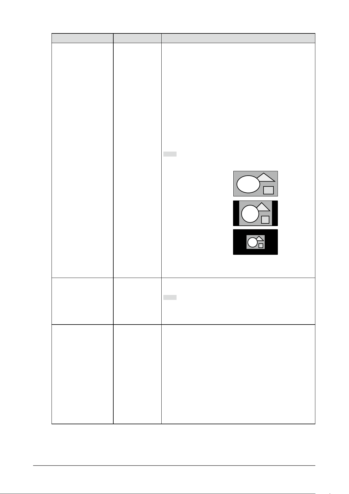
Function Setting Value Description
Picture Expansion Auto
*1
Full Screen
Aspect Ratio
Dot by Dot
The screen size of the monitor display can be changed.
• “Auto”
The monitor automatically changes the screen size
according to the aspect ratio and resolution information
from the PC.
• “Full Screen”
Images are stretched to full screen. Since aspect ratios are
not maintained, images may be distorted in some cases.
• “Aspect Ratio”
Images are enlarged to full screen without changing the
aspect ratio. Since aspect ratios are maintained, blank
horizontal or vertical borders may appear.
• “Dot by Dot”
Displays the image at the set resolution or size specied by
the input signal.
Note
• Example settings
- Full Screen
- Aspect Ratio
- Dot by Dot
(input signal)
• During PinP display, the aspect ratio of the small window is
xed and therefore the display size of the window cannot
be changed.
Input Color Format Auto
YUV 4:2:2
YUV 4:4:4
YUV
RGB
*1
*1
*2
The color format of the input signal can be specied.
Try changing this setting if colors are not displayed correctly.
Note
• This setting is required when a DVI device is connected to
the monitor via the HDMI connector port using a DVI-HDMI
conversion connector.
Input Range Auto
Full
Limited
Depending on the PC, black and white of the video level of the
signal output to the monitor may be limited. If a limited signal is
displayed on the monitor, black will appear faint and white will
appear dull, leading to a reduction in contrast. The output range
of such signals can be extended to match the actual contrast
ratio of the monitor.
• “Auto”
Automatically identies the brightness range of the input
signal and displays the image accordingly.
• “Full”
Extension of the signal output range is not performed.
• “Limited”
Extends the signal output range through 0 to 255 and
displays the image.
*1 Only enabled during HDMI input
*2 Only enabled during DisplayPort input or USB-C input
Chapter 3 Advanced Adjustment / Setting
27
Page 28

Preference Settings
●
The monitor’s settings can be congured to suit the usage environment or personal preference.
Function
USB CHARGE
Port
Power Save On
Power Indicator On
Normal
Charging Only
Off
Off
Setting
Value
Description
The USB downstream port of the monitor supports boost charging via
USB 3.0. By changing this setting to “Charging Only”, the device connected
to the
would be required when it is set to “Normal”.
Note
• Before changing this setting, terminate communication between the
• The device connected to the
• When this is set to “Charging Only”, data communication cannot be
• When this is set to “Charging Only”, charging is possible even when the
The monitor can be set to enter power saving mode according to the state of
the PC.
The monitor changes to power saving mode about 15 seconds after signal
input ceases to be detected.
When the monitor has shifted to power saving mode, images are not
displayed on the screen.
• Exiting power saving mode
Note
• At the time of shifting to power saving mode, a message that indicates
• During PbyP/PinP display, the monitor only enters the power saving
• When not using the monitor, you can turn off the main power supply or
• When the monitor is in power saving mode, devices connected to the
The power indicator (white) can be turned off in normal operation mode.
port can be charged in a shorter period of time than that which
PC any USB devices connected to the monitor. All communication is
temporarily interrupted when the setting is changed.
port must support boost charging.
established between the device connected to the
and the device will not operate.
monitor is not connected to the PC using a USB cable.
- If the monitor receives input, it automatically exits power saving mode
and returns to the normal display mode.
the transition is displayed 5 seconds in advance.
mode when signals are not input from all PCs.
disconnect the power plug so that the power is cut completely.
USB downstream port will still work. Therefore, power consumption of
the monitor varies with connected devices even in power saving mode.
port and the PC,
Chapter 3 Advanced Adjustment / Setting
28
Page 29
Function
Sound
Selection
Monitor Reset - Restore all settings to their default values except for the following settings.
Setting
Value
Left
Right
Upper Left
Lower Left
Upper Right
Lower Right
Large Window
Small Window
Description
Select the source of audio to output from the monitor during PbyP/PinP
display.
• “Left”
Outputs the audio source from the left screen during PbyP display (dual
screen).
• “Right”
Outputs the audio source from the right screen during PbyP display (dual
screen).
• “Upper Left”
Outputs the audio source from the upper left screen during PbyP display
(quad screen).
• “Lower Left”
Outputs the audio source from the lower left screen during PbyP display
(quad screen).
• “Upper Right”
Outputs the audio source from the upper right screen during PbyP
display (quad screen).
• “Lower Right”
Outputs the audio source from the lower right screen during PbyP display
(quad screen).
• “Large Window”
Outputs the audio source from the large window during PinP display.
• “Small Window”
Outputs the audio source from the small window during PinP display.
Note
• Enabled only during PbyP/PinP display.
• For details on PbyP/PinP, see “2-2. Switching Input Signals” (page 15).
• PbyP/PinP Picture Setup
• Settings on the “Administrator Settings” menu
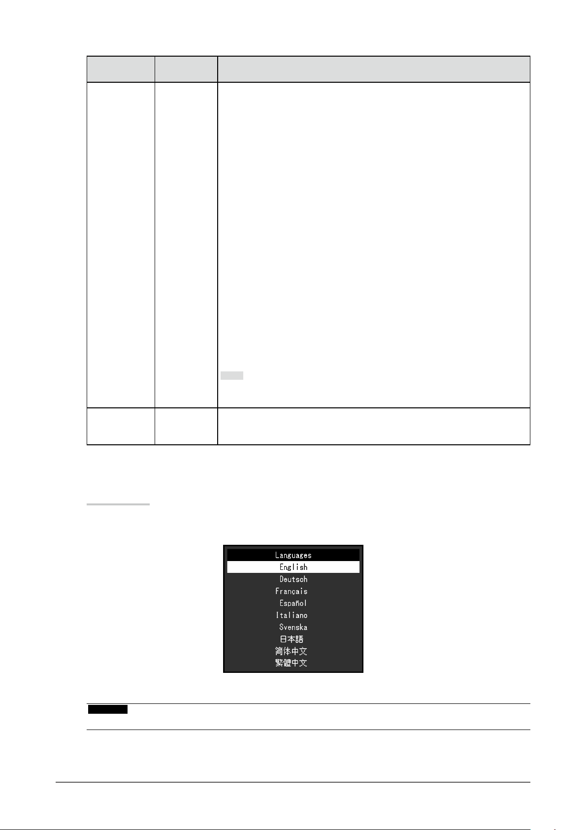
Language
●
The display language for menus and messages can be selected.
Setting Value
English, German, French, Spanish, Italian, Swedish, Japanese, Simplied Chinese, Traditional
Chinese
Attention
• The display language of the “Administrator Settings” menu cannot be changed.
Chapter 3 Advanced Adjustment / Setting
29
Page 30
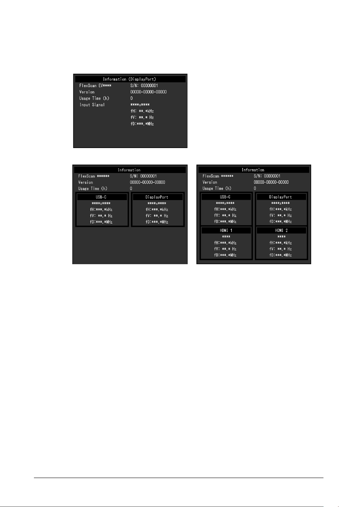
Information
●
Monitor information (product name, serial number, usage time, resolution, and input signal) can be
checked.
Example: • Single screen display
• Dual PbyP/PinP display • Quad PbyP display
Chapter 3 Advanced Adjustment / Setting
30
Page 31
Chapter 4 Administrator Settings
This chapter describes how to congure monitor operation using the “Administrator Settings” menu.
This menu is for administrators. Conguration on this menu is not required for normal monitor use.
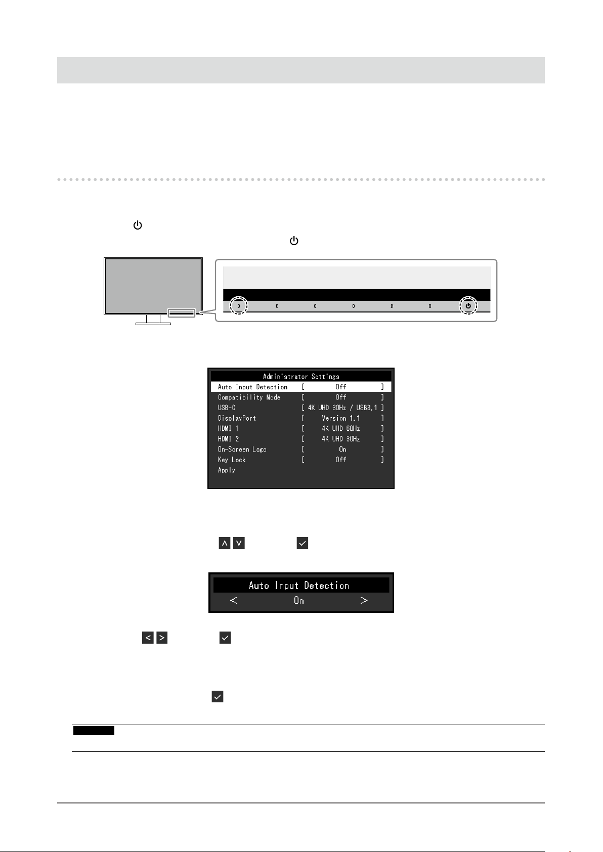
4-1. Basic Operation of the “Administrator Settings”
Menu
Menu display
1.
1. Touch to turn off the monitor.
2. While touching the leftmost switch, touch
The “Administrator Settings” menu appears.
for more than 2 seconds to turn on the monitor.
Setting
2.
1. Select an item to set with and select .
The Adjustment / Setting menu appears.
2. Set with and select .
The “Administrator Settings” menu appears.
Applying and exiting
3.
1. Select “Apply” and then .
The settings are applied and the “Administrator Settings” menu exits.
Attention
• The language (English) of the “Administrator Settings” menu cannot be changed.
Chapter 4 Administrator Settings
31
Page 32

4-2. Functions of the “Administrator Settings” Menu
Function Setting Value Description
Auto Input Detection On
Off
Compatibility Mode On
Off
USB-C 4K UHD 60Hz / USB2.0
4K UHD 30Hz / USB3.1
DisplayPort Version 1.1
Version 1.2
This function automatically recognizes the connector through
which PC signals are input, and displays images on the
screen accordingly.
• “On”
When the monitor is connected to multiple PCs, if a
specic PC enters power saving mode or no signals
are input to the monitor, the connector is automatically
changed to another one to which signals are input.
• “Off”
This function displays the signal from the selected
connector regardless of whether a signal is input or not.
In this case, you can select the input signal to display
using the
For details, see “2-2. Switching Input Signals” (page
15).
Note
• This function is not available during PbyP/PinP display.
• This product automatically recognizes the connector
through which PC signals are input, and displays images
on the screen accordingly regardless of whether this
function is set to On or Off just after the main power
switch on the rear side of the monitor has been turned
on.
• When this function is set to “On”, the monitor only enters
the power saving mode when signals are not input from
any PC.
If you want to avoid the following phenomena, set this function
to "On".
• The positions of windows and icons are shifted when the
monitor is turned off / on or has returned from the power
saving mode.
• Power Save function of the PC does not work normally.
• During USB-C input, the screen blinks two or three times
immediately after the USB cable has been connected or
the PC has returned from the Power Save mode.
• When the power to the monitor is turned off, a device
connected to the USB downstream port does not work.
• When the monitor is turned off, a device connected via a
USB-C connector cannot be recharged.
The USB setting and the types of signals that the monitor can
display can be changed.
The types of signals that the monitor can display can be
changed.
operation switch on the front of the monitor.
Chapter 4 Administrator Settings
32
Page 33

Function Setting Value Description
HDMI 1 4K UHD 60Hz
4K UHD 30Hz
HDMI 2 4K UHD 60Hz
4K UHD 30Hz
On-Screen Logo On
Off
Key Lock Off
Menu
All
The types of signals that the monitor can display can be
changed.
Note
• If the HDMI signal that is being input is not displayed,
change this setting.
The types of signals that the monitor can display can be
changed.
Note
• If the HDMI signal that is being input is not displayed,
change this setting.
When the monitor is turned on, the EIZO logo appears on the
screen.
When this function is set to “Off”, the EIZO logo does not
appear.
In order to prevent changes to settings, the operation
switches on the front of the monitor can be locked.
• “Off” (default setting)
Enables all switches.
• “Menu”
Locks the
• “All”
Locks all switches except the power switch.
switch.
Chapter 4 Administrator Settings
33
Page 34

Chapter 5 Troubleshooting
5-1. No Picture
Problem Possible cause and remedy
1. No picture
• Power indicator does not light up.
• Power indicator is lighting white. • Increase “Brightness”, “Contrast”, or “Gain” in the Setting menu (see
• Power indicator is lighting orange. • Switch the input signal.
• Power indicator is ashing orange
and white.
2. The message below appears. This message appears when the signal is not input correctly even
• This message appears when no
signal is input.
Example:
• The message shows that the
input signal is out of the specied
frequency range.
Example:
• Check whether the power cord is connected properly.
• Turn on the main power switch on the rear side of the monitor.
• To u c h
• Turn off the main power switch on the rear side of the monitor, and
then turn it on again a few minutes later.
“Color Adjustment” (page 23)).
• Turn the setting “On” for “Compatibility Mode” on the “Administrator
Settings” menu (see “Compatibility Mode” (page 32)).
• Move the mouse or press any key on the keyboard.
• Check whether the PC is turned on.
• Turn off the main power switch on the rear side of the monitor, and
then turn it on again.
• This symptom may occur during DisplayPort input.
• This symptom may occur during USB-C input.
though the monitor is functioning properly.
• The message shown left may appear, because some PCs do not
output the signal immediately after power-on.
• Check whether the PC is turned on.
• Check whether the signal cable is connected properly.
• Switch the input signal.
• Turn off the main power switch on the rear side of the monitor, and
then turn it on again.
• Check whether the PC is congured to meet the resolution and
vertical scan frequency requirements of the monitor (see “1-3.
Supported Resolutions” (page 10)).
• Reboot the PC.
• Select an appropriate setting using the graphics board’s utility. Refer
to the User’s Manual of the graphics board for details.
.
- Use a signal cable recommended by us for the connection. Turn
the monitor off and on.
- Disconnect and connect the USB cable that is plugged in to the
upstream port (USB-C).
- Turn off the main power switch on the rear side of the monitor, and
then turn it on again.
• This message shows that a device
that is not compatible with DP Alt
Mode is connected to the USB-C
connector.
Example:
Chapter 5 Troubleshooting
34
• Check whether a signal cable recommended by us is used.
• Check whether the connected device is compatible with DP Alt
Mode. Contact the device manufacturer for information about
compatibility with DP Alt Mode.
• Please connect it via a DisplayPort cable or HDMI cable.
Page 35

5-2. Imaging Problems
Problem Possible cause and remedy
1. The screen is too bright or too
dark.
2. Brightness cannot be changed or
it changes on its own.
3. Text is blurred. • Check whether the PC is congured to meet the resolution and
4. Afterimages appear. • Afterimages are particular to LCD monitors. Avoid displaying the
5. Green / red / blue / white / dark
dots remain on the screen.
6. Interference patterns or pressure
marks remain on the screen.
7. Noise appears on the screen. • In the Setting menu, set “Overdrive” to “Off” (see “Overdrive” (page
8. The positions of windows and
icons are shifted when the
monitor is turned off / on or when
restored from power saving mode.
9. The color shown on the screen is
not correct.
10. Images are not displayed over the
entire area of the screen.
• Use “Brightness” or “Contrast” in the Setting menu to adjust it (see
“Color Adjustment” (page 23)). (The LCD monitor backlight has
a limited life span. If the screen becomes dark or begins to icker,
contact your local EIZO representative.)
• If the screen is too bright, try changing the Auto EcoView setting
to “On”. The monitor detects the ambient brightness to adjust the
screen brightness automatically (see “Auto EcoView” (page 20)).
• Try changing the Auto EcoView setting to “Off” (see “Auto EcoView”
(page 20)).
vertical scan frequency requirements of the monitor (see “1-3.
Supported Resolutions” (page 10)).
same image for a long time.
• Use the screen saver or power saving function to avoid displaying
the same image for extended periods of time. Depending on the
image, an afterimage may appear even if it was displayed for a short
period of time. To remove such a phenomenon, change the image
or keep the power turned off for several hours.
• This is due to LCD panel characteristics and not a malfunction.
• Leave the monitor with a white or black screen. The symptom may
disappear.
25)).
• When inputting HDCP system signals, normal images may not be
displayed immediately.
• Turn the setting “On” for “Compatibility Mode” on the “Administrator
Settings” menu (see “Compatibility Mode” (page 32)).
• Try changing “Input Color Format” in the Setting menu (see “Input
Color Format” (page 27)).
• Try changing “Picture Expansion” in the Setting menu (see “Picture
Expansion” (page 27)).
Chapter 5 Troubleshooting
35
Page 36

5-3. Other Problems
Problem Possible cause and remedy
1. The Setting menu does not
appear.
2. Cannot select items in the
Settings menu.
3. No audio output. • Check whether volume is set to 0.
4. USB devices connected to the
monitor do not work.
5. Powerindicatorisashingorange
and white.
6. Power Save function of the PC
does not work normally.
• Check whether the switch operation lock function is active (see “Key
Lock” (page 33)).
• Items that are displayed with gray text cannot be changed.
• Check the PC and audio playback software to see whether they are
congured correctly.
• Check the “Sound Selection” setting during PbyP/PinP display (see
“Sound Selection” (page 29)).
• Check whether the USB cable is correctly connected between the
PC and the monitor (see “6-5. Using the USB Hub Function” (page
43)).
• Check whether the USB CHARGE port is set correctly (see “USB
CHARGE Port” (page 28)).
• Check whether the USB cable is correctly connected between the
peripheral and the monitor.
• Try using a different USB port on the monitor.
• Try using a different USB port on the PC.
• Reboot the PC.
• If the peripheral devices work correctly when they are directly
connected to the PC, contact your local EIZO representative.
• Depending on the USB 3.1 host controller that you are using,
connected USB devices may not be recognized correctly. Update to
the latest USB 3.1 driver provided by each manufacturer, or connect
the monitor to the USB 2.0 port.
• Check the PC’s BIOS setting for USB when using Windows. (Refer
to the manual of the PC for details.)
• This symptom may occur when the PC is connected to the
DisplayPort connector. Use a signal cable recommended by us for
the connection. Turn the monitor off and on.
• Check the connection and condition of the USB devices connected
to the monitor.
• Turn off the main power switch on the rear side of the monitor, and
then turn it on again.
• Turn the setting “On” for “Compatibility Mode” on the “Administrator
Settings” menu (see “Compatibility Mode” (page 32)).
Chapter 5 Troubleshooting
36
Page 37

Chapter 6 Reference
6-1. Attaching the Optional Arm
An optional arm (or an optional stand) can be attached by removing the stand section. Please refer to our
web site for the supported optional arm (or optional stand). http://www.eizoglobal.com
Attention
• When attaching an arm or stand, follow the instructions of the respective User’s Manual.
• When using another manufacturer’s arm or stand, conrm the following in advance and select one conforming to
the VESA standard. Use the VESA mounting screws supplied with this product when attaching the arm or stand.
- Clearance between screw holes: 100 mm × 100 mm
- VESA mount of the arm or stand, external dimensions: 122 mm x 122 mm or less
- Plate thickness: 2.6 mm
- Strong enough to support weight of the monitor unit (excluding the stand) and attachments such as cables.
• When attaching an arm or stand, the installable orientations and movement range (tilt angle) are as follows:
Orientation
Movement range
(tilt angle)
Up: 45˚ Down: 45˚
• Connect the cables after attaching an arm or stand.
• Do not move the removed stand up and down. Doing so may result in injury or device damage.
• The monitor, arm, and stand are heavy. Dropping them may result in injury or equipment damage.
Chapter 6 Reference
37
Page 38

Attaching the optional arm (or optional stand)
●
1. Lay the LCD monitor on a soft cloth spread over a stable and at surface with the panel surface
facing down.
2. Remove the stand.
As shown in the gure, while holding down the lock button (1), slide the stand toward the stand base until it
touches the stand base (2). Then, lift the stand up (3).
(3)
(1)
(2)
3. Attach the arm or stand to the monitor.
Use the VESA mounting screws supplied with this product when attaching the arm or stand.
Attaching the original stand
●
1. Lay the LCD monitor on a soft cloth spread over a stable and at surface with the panel surface
facing down.
2. Remove the xing screws on the optional arm (or optional stand), and detach the optional arm (or
optional stand).
3. Attach the original stand.
Insert the four tabs on the stand into the four holes on the back panel (1), and slide the stand towards the
upper portion of the monitor (2). The stand clicks when it is attached correctly.
(1)
(2)
Click!
Chapter 6 Reference
38
Page 39
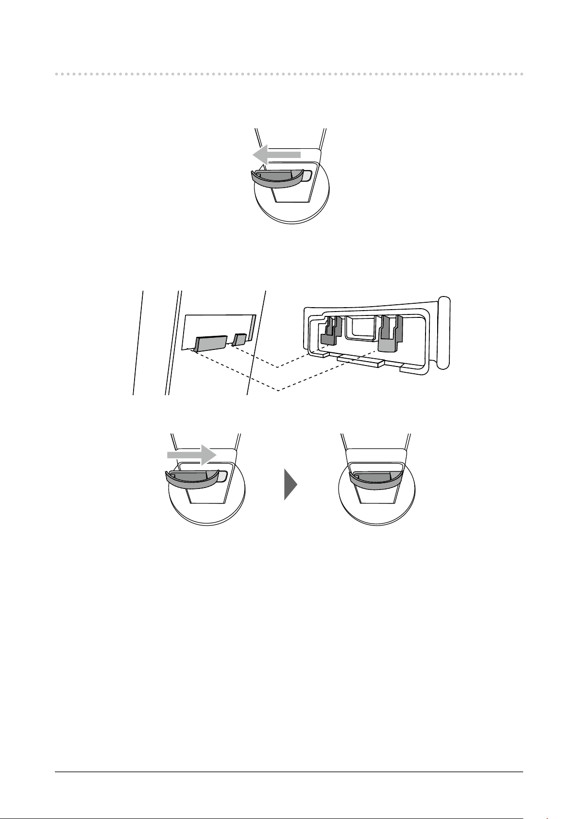
6-2. Detaching/Attaching the Cable Holder
Detaching the cable holder
●
1. Slide the cable holder to the left, and detach it from the stand.
Attaching the cable holder
●
1. Align the tabs of the cable holder with the attachment parts of the stand.
2. Slide the cable holder to the right, and attach it to the stand.
Chapter 6 Reference
39
Page 40

6-3. Detaching / Attaching the Cable Cover
Attaching the cable cover
●
A B
1. Align the tabs of (A) with the attachment parts of the stand.
A
2. Slide (A) downward to secure the tabs to the attachment parts of the stand.
3. Check the tabs of (B) (four locations indicated by ) and the attachment locations of (A).
A
B
Chapter 6 Reference
40
Page 41

4. Pass the cables between (A) and (B), and align (B) with (A) to t in.
5. Slide (B) downward and secure it to (A).
Detaching the cable cover
●
1. Slide (B) upward, and detach it from (A).
2. While holding down of (A) lightly, slide (A) upward to detach it from the stand.
Chapter 6 Reference
41
Page 42
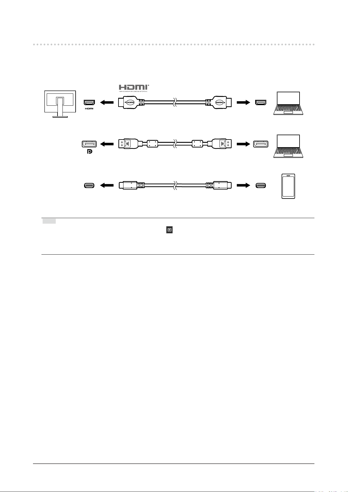
6-4. Connecting Multiple PCs
This product can be connected to multiple PCs and allows you to switch between the connections for
display.
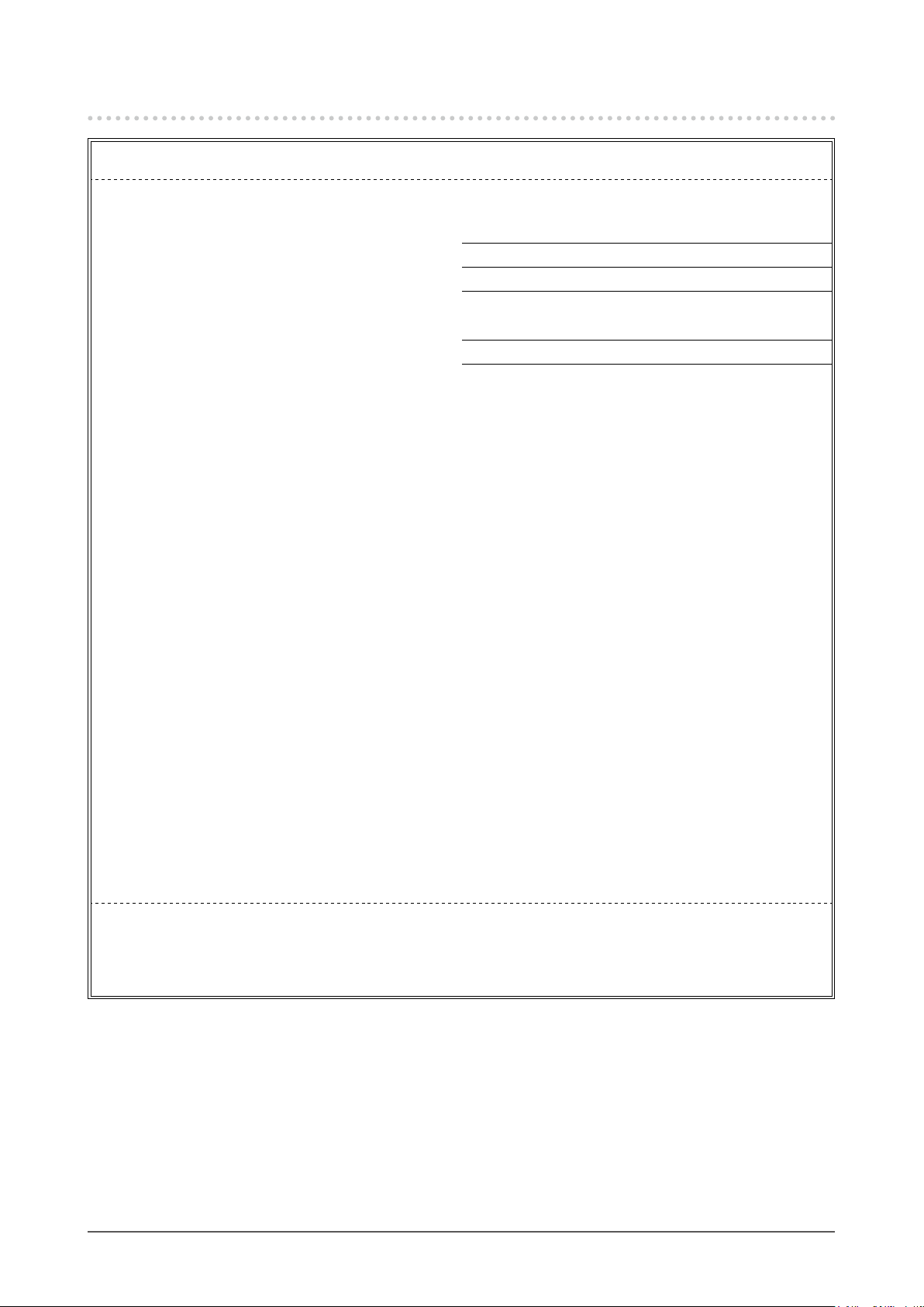
Connection examples
●
HH200PR (HDMI - HDMI) HDMIHDMI
(supplied)
DisplayPort
USB-C CC200SS (USB-C - USB-C) USB-C
Note
• You can select the input signal to display using the operation switch on the front of the monitor. For details, see
“2-2. Switching Input Signals” (page 15).
• This product provides a function that automatically recognizes the connector through which PC signals are input,
and displays images on the screen accordingly. For details, see “Auto Input Detection” (page 32).
PP200 (DisplayPort - DisplayPort)
(supplied)
(supplied)
DisplayPort
Chapter 6 Reference
42
Page 43
6-5. Using the USB Hub Function
This monitor is equipped with a USB hub. It functions as a USB hub when connected to a USBcompatible PC, allowing the connection of peripheral USB devices.
Connection procedure
●
1. Connect the USB cable between the USB-C connectors of the PC and the monitor.
2. Connect a peripheral USB device to the USB downstream port of the monitor
Attention
• If your PC is not equipped with a USB-C connector, a USB-C to Type-A conversion cable is required. Connect the
conversion cable between the USB downstream port of the PC and the USB-C connector of the monitor.
• When you change the setting of “Compatibility Mode” (page 32), remove any peripherals such as a USB
memory device connected to the downstream port of the monitor.
• When the main power of the monitor is off, a device connected to the USB downstream port will not operate.
• When “Compatibility Mode” (page 32) is set to "Off" and the power to the monitor is turned off, a device
connected to the USB downstream port will not work.
Note
• This product supports USB 3.1*1. When connecting to peripheral devices that support USB 3.1, high-speed data
communication is possible (however, only when the USB cable used to connect the PC and peripheral device is
USB 3.1 compliant and “USB-C” in the “Administrator Settings” menu is set to “4K UHD 30Hz / USB3.1”) (page
32).
*1 Only Gen1 5 Gbps is supported.
.
Chapter 6 Reference
43
Page 44

6-6. Specications
LCD Panel Type IPS (Anti-Glare)
Backlight LED
Size 80.0 cm (31.5 inch)
Resolution 3840 dots x 2160 lines
Display Size (H × V) 697.3 mm × 392.2 mm
Pixel Pitch 0.182 mm
Display Colors 8-bit colors: 16.77 million colors
Viewing Angle
(H / V, typical)
Response Time (typical) Gray-to-gray: 14 ms (overdrive setting: Off)
Video Signals Input Terminals DisplayPort (HDCP) × 1, HDMI (HDCP)*1 × 2, USB-C (HDCP) × 1
Digital Scanning
Frequency
(H / V)
Frame Synchronization
Mode
Max. Dot Clock DisplayPort: 540 MHz
USB Port Upstream port (USB-C) x 1
Standard USB Specication Revision 3.1
Communication Speed 5 Gbps (super), 480 Mbps (high), 12 Mbps (full), 1.5 Mbps (low)
Supply Current
Audio Audio Input Format DisplayPort: 2ch linear PCM (32 kHz / 44.1 kHz /
Speakers 1 W + +1 W
Headphones 2 mW + +2 mW (32 Ω)
Input Terminals DisplayPort × 1, HDMI × 2, USB-C × 1 (each shared with video signal)
Output Terminals Stereo mini jack × 1
178˚ / 178˚
5 ms (overdrive setting: Enhanced)
DisplayPort: 31 kHz to 134 kHz /
29 Hz to 31 Hz, 59 Hz to 61 Hz,
69 Hz to 71 Hz (at 720 × 400)
HDMI: 31 kHz to 135 kHz /
29 Hz to 31 Hz, 49 Hz to 61 Hz,
69 Hz to 71 Hz (at 720 × 400)
USB-C (DP Alt Mode): 31 kHz to 134 kHz /
29 Hz to 31 Hz, 59 Hz to 61 Hz,
69 Hz to 71 Hz (at 720 × 400)
59.5 Hz to 60.5 Hz
HDMI: 600 MHz
USB-C (DP Alt Mode): 540 MHz
Downstream port (USB Type-A) x 2 (The
charging)
*2
, Battery Charging Revision 1.2
Downstream
(USB Type-A):
Downstream
(USB Type-A,
port):
Upstream (USB-C): Max. 60 W
USB-C (DP Alt Mode): 2ch linear PCM (32 kHz / 44.1 kHz /
HDMI: 2ch linear PCM (32 kHz / 44.1 kHz /
Max. 900 mA
Max. 1.5 A (Normal)
Max. 2.1 A (Charging only)
48 kHz / 88.2 kHz / 96 kHz / 176.4 kHz /
192 kHz)
48 kHz / 88.2 kHz / 96 kHz / 176.4 kHz /
192 kHz)
48 kHz/ 88.2 kHz / 96 kHz / 176.4 kHz /
192 kHz)
port supports boost
Chapter 6 Reference
44
Page 45

Power Input 100 - 240 VAC ±10 %, 50 / 60 Hz 1.65 A - 0.75 A
Maximum Power
Consumption
Power Save Mode 0.5 W or less (no USB device connected, default settings)
Standby Mode 0.5 W or less (no USB device connected, default settings)
Physical
Specications
Operating
Environmental
Requirements
Transportation /
Storage
Environmental
Requirements
*1 HDMI CEC (or mutual control) is not supported.
*2 Only Gen1 5 Gbps is supported.
Dimensions 717.4 mm × 396.1 mm to 591.1 mm × 253.4 mm to 287.8 mm
Dimensions
(Without Stand)
Net Weight Approx. 11 kg
Net Weight (Without
Stand)
Height Adjustment
Range
Tilt Up 35˚, down 5˚
Swivel 344˚
Temperature 5 ˚C to 35 ˚C
Humidity 20 % to 80 % R.H. (no condensation)
Air Pressure 540 hPa to 1060 hPa
Temperature -20 ˚C to 60 ˚C
Humidity 10 % to 90 % R.H. (no condensation)
Air Pressure 200 hPa to 1060 hPa
163 W or less
(W × H × D) (Tilt: 35˚)
717.4 mm × 427.3 mm to 576.2 mm × 230 mm
(W × H × D) (Tilt: 0˚)
717.4 mm × 416.3 mm × 51.5 mm (W × H × D)
Approx. 7.6 kg
195 mm (Tilt: 35˚) / 148.9 mm (Tilt: 0˚)
Accessories
●
For the latest information about accessories, refer to our web site. http://www.eizoglobal.com
Chapter 6 Reference
45
Page 46
Appendix
Trademark
The terms HDMI and HDMI High-Denition Multimedia Interface, and the HDMI Logo are trademarks or
registered trademarks of HDMI Licensing, LLC in the United States and other countries.
The DisplayPort Compliance Logo and VESA are registered trademarks of the Video Electronics
Standards Association.
The SuperSpeed USB Trident Logo is a registered trademark of USB Implementers
Forum, Inc.
The USB Power Delivery Trident logos are trademarks of USB Implementers Forum, Inc.
DICOM is the registered trademark of the National Electrical Manufacturers Association for its standards
publications relating to digital communications of medical information.
Kensington and Microsaver are registered trademarks of ACCO Brands Corporation.
Thunderbolt is a trademark of Intel Corporation in the United States and/or other countries.
Microsoft and Windows are registered trademarks of Microsoft Corporation in the United States and
other countries.
Adobe is a registered trademark of Adobe Systems Incorporated in the United States and other
countries.
Apple, macOS, Mac OS, OS X, Macintosh and ColorSync are registered trademarks of Apple Inc.
EIZO, the EIZO Logo, ColorEdge, CuratOR, DuraVision, FlexScan, FORIS, RadiCS, RadiForce,
RadiNET, Raptor and ScreenManager are registered trademarks of EIZO Corporation in Japan and other
countries.
ColorEdge Tablet Controller, ColorNavigator, EcoView NET, EIZO EasyPIX, EIZO Monitor Congurator,
EIZO ScreenSlicer, G-Ignition, i•Sound, Quick Color Match, RadiLight, Re/Vue, Screen Administrator,
Screen InStyle and UniColor Pro are trademarks of EIZO Corporation.
All other company and product names are trademarks or registered trademarks of their respective
owners.
License
The bitmap font used for this product is designed by Ricoh Industrial Solutions Inc.
ENERGY STAR
As an ENERGY STAR Partner, EIZO Corporation has determined that this product meets
the ENERGY STAR guidelines for energy efciency.
Appendix
46
Page 47
FCC Declaration of Conformity
For U.S.A., Canada Only
FCC Declaration of Conformity
We, the Responsible Party EIZO Inc.
5710 Warland Drive, Cypress, CA 90630
Phone: (562) 431-5011
declare that the product Trade name: EIZO
Model: FlexScan EV3285
is in conformity with Part 15 of the FCC Rules. Operation of this product is subject to the following two
conditions: (1) this device may not cause harmful interference, and (2) this device must accept any
interference received, including interference that may cause undesired operation.
This equipment has been tested and found to comply with the limits for a Class B digital device, pursuant
to Part 15 of the FCC Rules. These limits are designed to provide reasonable protection against
harmful interference in a residential installation. This equipment generates, uses, and can radiate radio
frequency energy and, if not installed and used in accordance with the instructions, may cause harmful
interference to radio communications. However, there is no guarantee that interference will not occur in
a particular installation. If this equipment does cause harmful interference to radio or television reception,
which can be determined by turning the equipment off and on, the user is encouraged to try to correct
the interference by one or more of the following measures.
* Reorient or relocate the receiving antenna.
* Increase the separation between the equipment and receiver.
* Connect the equipment into an outlet on a circuit different from that to which the receiver is connected.
* Consult the dealer or an experienced radio/TV technician for help.
Changes or modications not expressly approved by the party responsible for compliance could void the
user’s authority to operate the equipment.
Note
Use the attached specied cable below or EIZO signal cable with this monitor so as to keep interference
within the limits of a Class B digital device.
- AC Cord
- Shielded Signal Cable (enclosed)
Canadian Notice
This Class B information technology equipment complies with Canadian ICES-003.
Cet équipement informatique de classe B est conforme à la norme NMB-003 du Canada.
Appendix
47
Page 48

03V27413B1
UM-EV3285
Copyright © 2018 EIZO Corporation. All rights reserved.
2nd Edition-October, 2018
 Loading...