

Page 1

English
Français
中
文
Deutsch
Setup Manual
Important:
Please read PRECAUTIONS, this Setup Manual and the User’s Manual
stored on the CD-ROM carefully to familiarize yourself with safe and
effective usage. Please retain this manual for future reference.
Installationshandbuch
Wichtig:
Manuel d’installation
Important : Veuillez lire attentivement les PRECAUTIONS, ce Manuel d’installation ainsi que
设定手册
重要事项: 请仔细阅读储存在光盘上的用户手册、本设定手册和预防措施、掌握如何
Lesen Sie die VORSICHTSMASSNAHMEN, dieses Handbuch zur Einrichtung
und das Benutzerhandbuch (auf der CD-ROM) aufmerksam durch, um sich mit
der sicheren und effizienten Bedienung vertraut zu machen. Bewahren Sie dieses Handbuch zum späteren Nachschlagen auf.
le Manuel d’utilisation inclus sur le CD-ROM, afin de vous familiariser avec ce
produit et de l’utiliser efficacement et en toute sécurité. Veuillez conserver ce
manuel pour référence ultérieure.
安全、有效地使用本产品。请保留本手册、以便今后参考。
Page 2
Compatible Resolutions/Frequencies
Kompatible Auflösungen/Bildwiederholfrequenzen
Résolutions/Fréquences compatibles
兼容的分辨率/频率
This monitor can be connected to a PC through either an analog or digital signal cable. The cable to be used depends
on the type of the PC.
For details, refer to "Connecting Cables" and confirm the shape of the connector of the PC.
The monitor supports the following resolutions.
Den Monitor können Sie entweder mit einem analogen oder einem digitalen Signalkabel an einen PC anschließen.
Welches Kabel Sie verwenden, hängt vom PC ab.
Nähere Informationen dazu finden Sie im Abschnitt „Kabel anschließen“. Achten Sie dabei bitte auch auf die richtige
Form der Steckdose am PC.
Der Monitor unterstützt die nachfolgend aufgeführten Auflösungen.
Ce moniteur peut être raccordé à un PC à l’aide d’un câble d’interface analogique ou numérique. Le câble utilisé est
fonction du type de PC.
Pour en savoir plus, reportez-vous à la rubrique « Connexion des câbles » puis validez la forme du connecteur du PC.
Le moniteur est compatible avec les résolutions suivantes.
本显示器可通过一根模拟信号电缆或数字信号电缆与个人计算机连接。选用何种电缆取决于个人计算机的类型。
如需有关详细信息,请参阅“连接电缆”并确认个人计算机的连接器的形状。
本显示器支持下列分辨率。
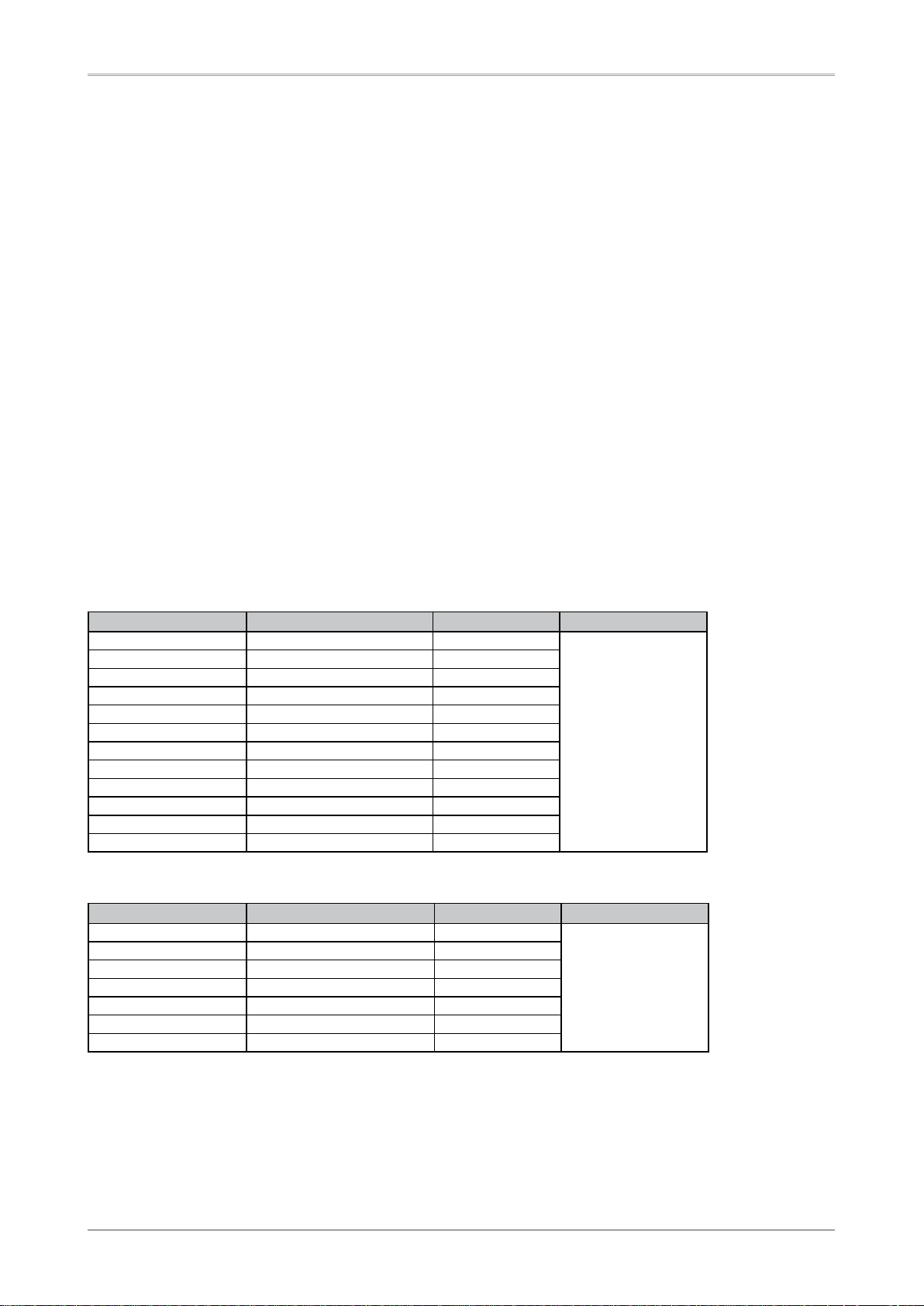
Analog Input
Resolution Display Mode Frequency Dot Clock
640 × 480 Apple Macintosh 67 Hz
640 × 480 VGA, VESA ~85 Hz
720 × 400 VGA TEXT 70 Hz
800 × 600
832 × 624 Apple Macintosh 75 Hz
1024 × 768
1152 × 864
1152 × 870 Apple Macintosh 75 Hz
1280 × 960
1280 × 960 Apple Macintosh 75 Hz
1280 × 1024
1680 × 1050
*
VESA CVT, VESA CVT RB 60 Hz
VESA ~85 Hz
VESA ~85 Hz
VESA 75 Hz
VESA 60 Hz
VESA ~75 Hz
150 MHz
(Max.)
Digital Input
Resolution Display Mode Frequency Dot Clock
640 × 480 VGA 60 Hz
720 × 400 VGA TEXT 70 Hz
800 × 600
1024 × 768
1280 × 960
1280 × 1024
1680 × 1050
*
Recommended resolusion (Set this resolution). When displaying the wide format input signal, a graphics board in conformance with
VESA CVT standard is required.
*
Empfohlene Auflösung (diese Auflösung festlegen). Zur Anzeige des Eingangssignals für das Breitbild ist eine Grafikkarte erforderlich,
die die Anforderungen des Standards VESA CVT erfüllt.
*
Résolution recommandée (Réglez votre appareil sur cette résolution). Lors de l’affichage du signal d’entrée format large, une carte
vidéo conforme à la norme VESA CVT est requise.
*
推荐的分辨率( 设定此分辨率 )。当显示宽荧幕格式输入信号时,需要符合 VESACVT 标准的显卡。
*
VESA 60 Hz
VESA 60 Hz
VESA 60 Hz
VESA 60 Hz
VESA CVT RB 60 Hz
120 MHz
(Max.)
Page 3
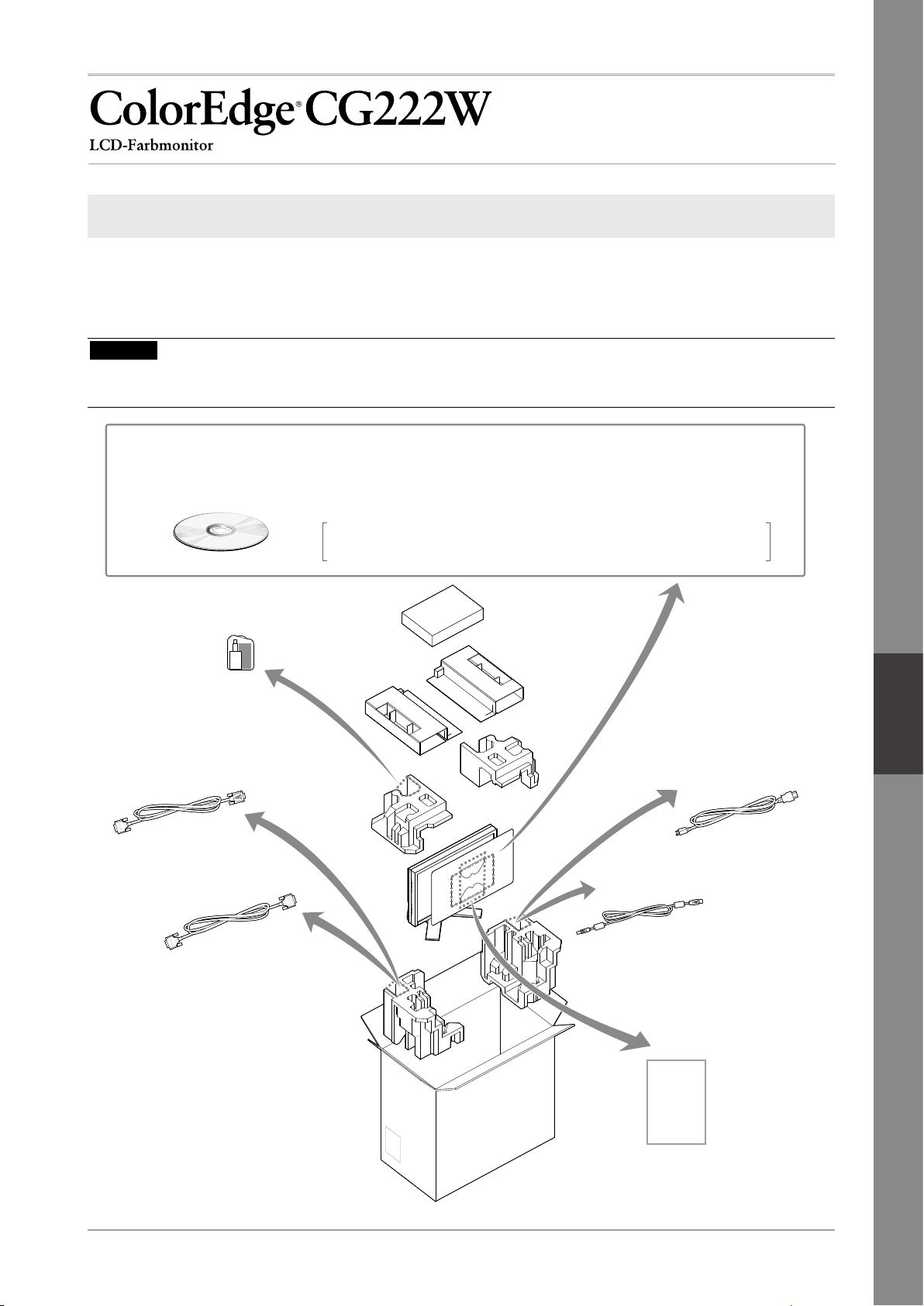
Checking Package Contents
English
Français
中
文
Deutsch
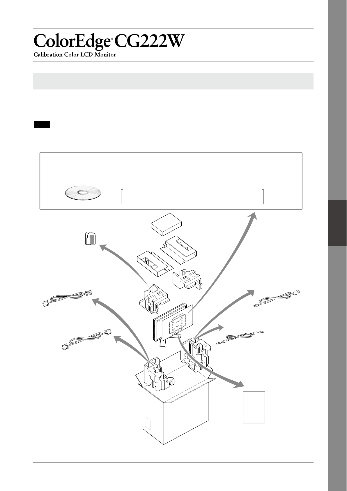
When removing the monitor from its packaging, remove accessories first, and then lift the monitor out gently.
Contact your local dealer if any items are missing or damaged.
The package contains the following items.
Note
•
Do not throw out the packaging (box and protective packaging). Keep it in a safe location. It will be required
when sending the unit in for repairs.
•
ColorNavigator Quick Reference
•
Recycling Information
Cleaning kit
“ScreenCleaner”
Analog signal cable
(FD-C16)
Digital signal cable
(FD-C39)
•
Setup Manual (this manual)
•
Mounting Screws (M4 x 12, 4 pcs)
•
EIZO LCD Utility Disk (CD-ROM)
•
Calibration software
ColorNavigator
Hood
Monitor
•
•
•
User’s Manuals (PDF format)
ColorEdge CG222W
ColorNavigator etc.
EIZO USB cable
(MD-C93)
Limited warranty
PRECAUTIONS
Power cord
Adjustment
Certificate
Adjustment Certificate
This sheet is attached to the “PAD-LCD”
LCD panel protection pad
.
1
Page 4
Controls and Functions
15
A
B
16
98762 31 4 5
1010
11 12 1413
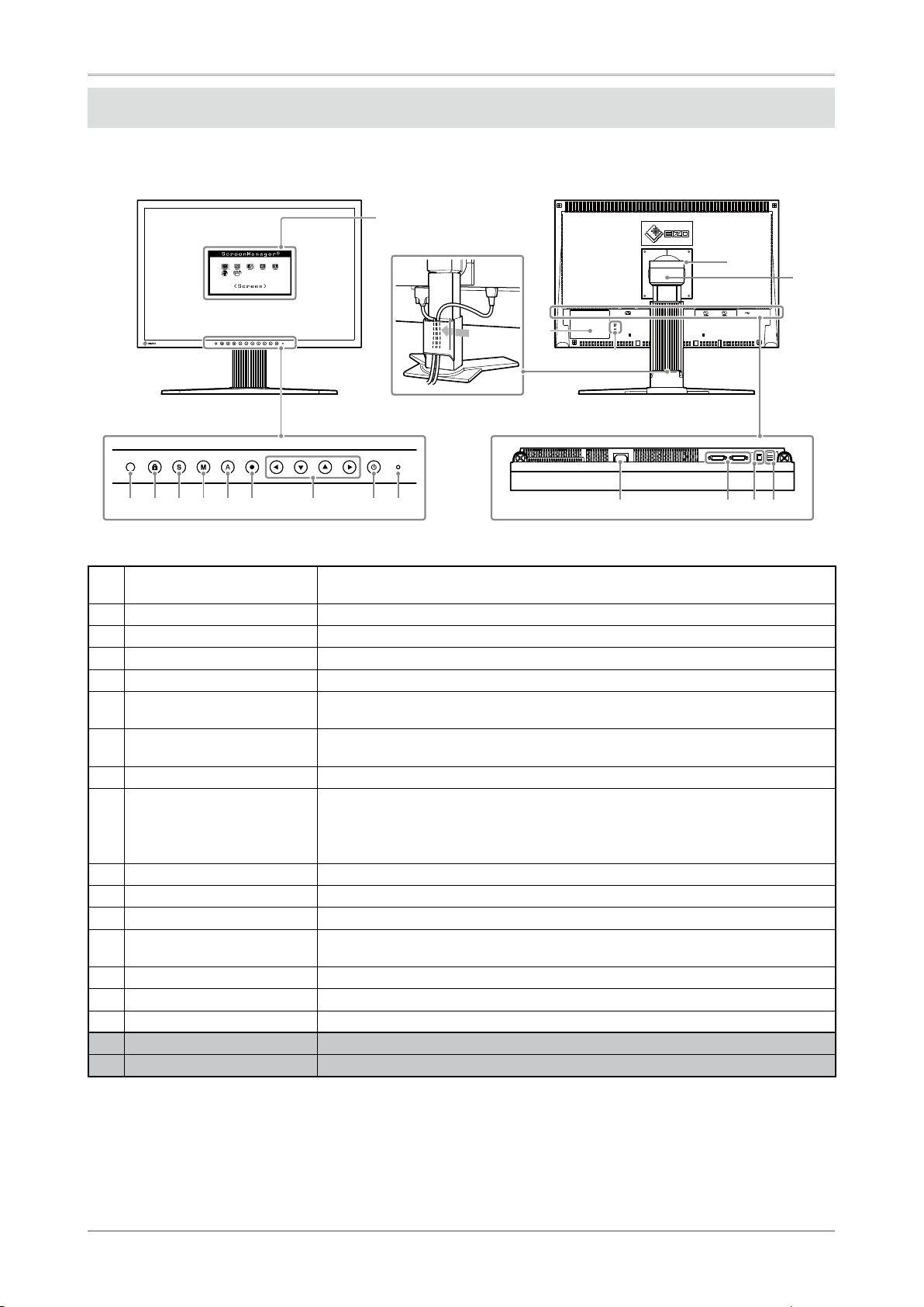
Display and adjustment buttons are located on the front of the monitor, and connectors are located on the rear.
The name and functions of the buttons and connectors are described below.
Adjustment menu
(ScreenManager
1 Sensor Detects ambient brightness. BrightRegulator function.
2 Adjustment Lock button This function locks the buttons to retain the status adjusted or set once.
3 Input Signal Selection button Switches input signals for display when two PCs are connected to the monitor.
4 Mode button Allows you to switch the display mode.
5 Auto button Performs the function to adjust the screen automatically. (analog input only)
6 Enter button Displays the Adjustment menu, determines an item on the menu screen, and
7 Control buttons
(Left, Down, Up, Right)
8 Power button Turns the power on or off.
9 Power indicator Indicates monitor’s operation status.
10 Security lock slot Complies with Kensington’s MicroSaver security system.
11 Power connector Connects the power connector.
12 Input signal connectors DVI-I Connector x 2
13 USB port (Up) Connects the USB cable in order to use the provided software. For how to use it,
14 USB port (Down) Connects a peripheral USB device.
15 Stand Used to adjust the height and angle of the monitor screen.
16 Cable holder Covers the monitor cables.
A Caution Statements The equipment must be connected to a grounded main outlet.
B Caution Statements CAUTION Risk of electric shock. Do not open.
* ScreenManager ® is an EIZO’s nickname of the Adjustment menu. (For how to use ScreenManager, refer to the User’s Manual on the CD-ROM.)
For details, refer to the User’s Manual on the CD-ROM.
saves values adjusted.
Chooses an adjustment item or increases/decreases adjusted values for
advanced adjustments using the Adjustment menu.
Blue: Operating Orange: Power saving Off: Power off
Flashing blue (2 times for each): When the timer is set for ColorNavigator,
notifies that a recalibration is required (for CAL mode or EMU mode).
refer to the User’s Manual on the CD-ROM.
® *
)
2
Page 5

Connecting Cables
English
Français
中
文
Deutsch
Connect the monitor to the PC. Turn the monitor, the PC, and all peripheral devices off before connecting the
cables. For details, refer to the User’s Manual contained in the supplied CD-ROM.
Connect to PCConnect to PC
Connect to monitor
Connect to monitor
Power cord
Connect to power outlet
Connect the monitor to the PC with a signal cable that matches the connectors.
1
After connecting the cable connectors, tighten the screws of the connectors to secure the coupling.
Connectors on the monitor cable Connectors on the PC
DVI-I
DVI-I
Connect the monitor to the PC with the USB cable.
2
Connect to the monitor Connect to the PC
[Analog signal cable]
FD-C16 Analog connection
[Digital signal cable]
FD-C39 Digital connection
USB cable
Digital/Analog signal cable
Note
• The USB cable is required for calibration. Be sure to connect the monitor and PC with the USB
cable.
Plug the power cord into a power outlet and the power connector on the monitor.
3
Press to turn on the monitor.
4
The monitor’s Power indicator lights up blue.
Turn on the PC.
5
The screen image appears.
If an image does not appear, refer to "No-Picture Problem" for additional advice.
Tips
•
When the PC and the monitor are turned off, monitor power is turned off completely, even
though the power cord is still connected to the monitor.
3
Page 6
Setting Resolution
When you connect the monitor to the PC and find that the resolution is improper, or when you want to change
the resolution, follow the procedure below.
Recommended resolution: 1680 dots x 1050 lines (60 Hz)
MacOS X
Select "System Preferences" from the Apple menu.
1
When the "System Preferences" dialog is displayed, click "Displays" for "Hardware".
2
On the displayed dialog, select the "Display" tab and select desired resolution in the "Resolutions" field.
3
Your selection will be reflected immediately. When you are satisfied with the selected resolution, close the
4
window.
Windows XP
Right-click the mouse anywhere on the desktop except for icons.
1
From the displayed menu, click "Properties".
2
When the "Display Properties" dialog is displayed, click the "Settings" tab and select desired resolution for
3
"Screen resolution" under "Display".
Click the "OK" button to close the dialog.
4
Windows Vista
Right-click the mouse anywhere on the desktop except for icons.
1
From the displayed menu, click "Personalize".
2
On the "Personalization" window, click "Display Settings".
3
On the "Display Settings" dialog, select the "Monitor" tab and select desired resolution in the
4
"Resolution" field.
Click the "OK" button.
5
When a confirmation dialog is displayed, click "Yes".
6
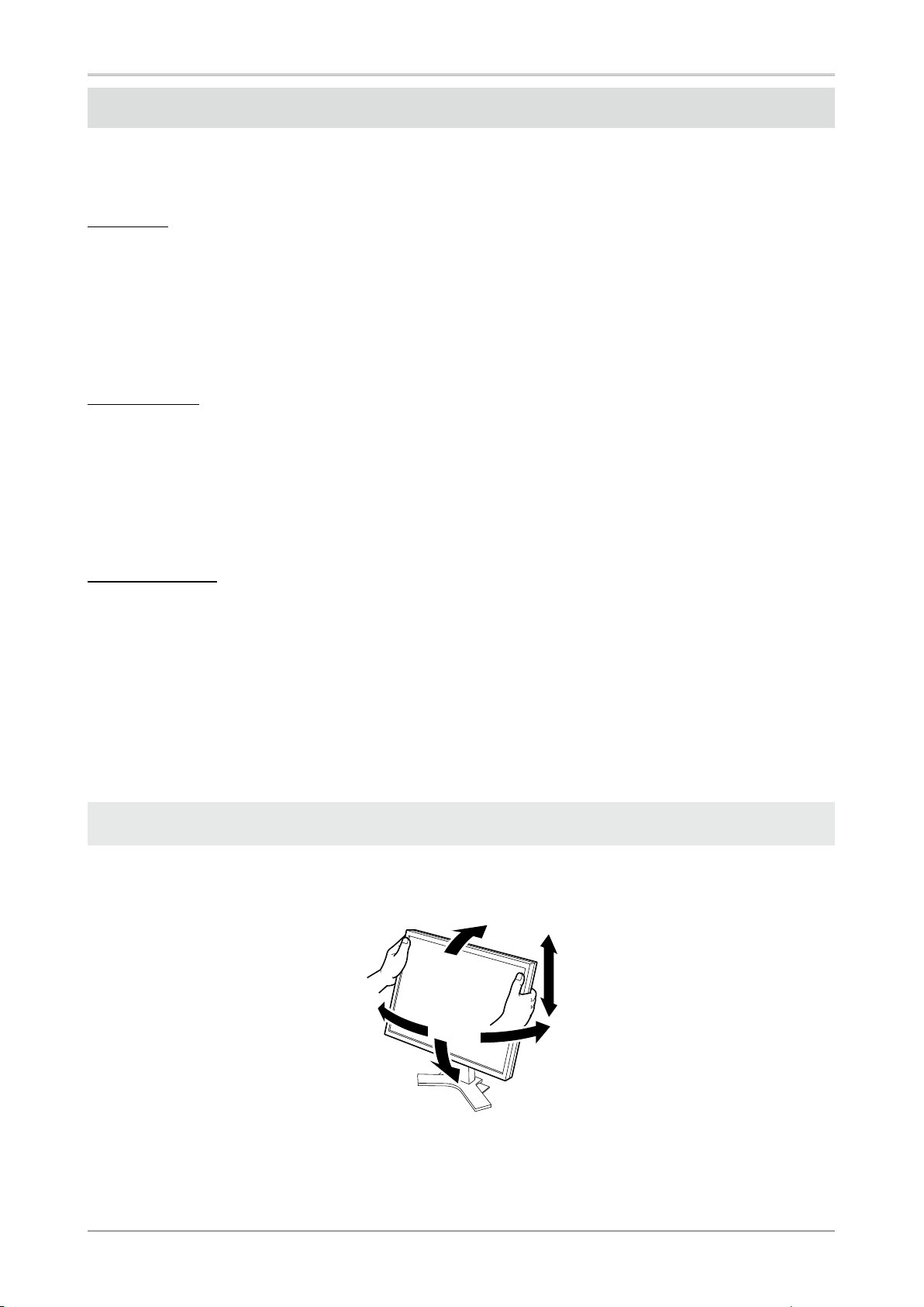
Adjusting the Monitor Height and Angle
The angle and height of the monitor can be adjusted.
Adjust the screen height and angle, tilt and swivel the screen to the best condition for working.
4
Page 7
How to Install the Hood
English
Français
中
文
Deutsch
CAUTION
Do not carry the monitor with the hood
attached.
While carrying the monitor, the hood may fall or slip
off, which may result in injury or equipment damage.
Close the open/close cover until it contacts the
stopper.
If the cover is not closed properly, the ventilation slots
on the monitor will be covered and proper airflow
will be prevented. This may cause overheating inside
the monitor and may result in fire, electric shock, or
equipment damage.
Package Contents
Check that all the following items are included in the packaging box.
Do not place any objects on the hood.
If the hood falls or slips off or the monitor falls over, it
may result in injury or equipment damage.
Do not rotate the monitor into the portrait
position.
Doing so may cause the hood to slip off, which may
result in injury or equipment damage.
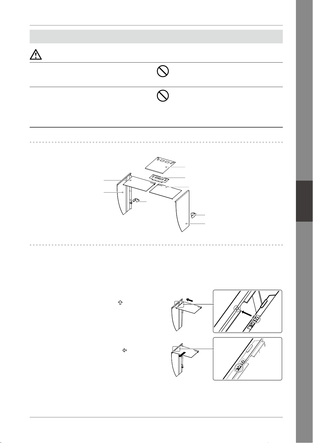
Open/close cover
Top cover
Left cover
Hook
Metal fitting
Top cover
Hook
Right Cover
Assemble the left and right hoods
Assemble the hoods in the direction of the arrows marked on the insertions on the top covers of the right
and left hoods.
Hold the left hood’s left and top covers with the sides with the anti-reflective sheet
1
facing inward.
Connect the top and left covers by
2
aligning the arrow (1 ) on the top
cover’s insertion with the two lines on
the left cover’s insertion slot.
Slide the top cover in the direction
3
shown by the arrow (2 ).
Assembly of the left hood is complete.
Assemble the right hood in the same way.
4
5
Page 8
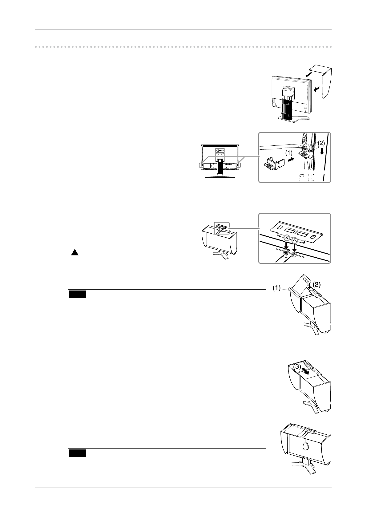
Attach the left and right hoods to the monitor
Be sure to install the second hood only after the other hood is firmly attached with hook.
Attach the top side of the left hood to the monitor first and
1
then securely fit the left side of the hood in order to fix the
hood to the monitor.
Insert the hook into the upper hole on
2
the hood (1) and slide it down along
the projection on the back side of the
monitor (2).
Attach the right hood in the same way.
3
Check the locations of the depressions
4
in the fitting and insert the fitting into
the left and right hoods by aligning
those depressions with the projections
( ) in the grooves on the right and left
hoods.
Insert into the
upper hole
Attach the open/close cover to the left hood.
5
Note
Do not attach the open/close cover to the right hood. Doing so prevents
•
the cover from closing.
Place the open/close cover on the top of the left hood (without
6
contacting the metal fitting) from front (1) to back (2).
Slide the open/close cover to the right (3) until it contacts the
7
stopper on the metal fitting.
When performing calibration, slide the open/close cover to the
8
left in order to attach the sensor.
Note
The open/close cover does not slide onto the right cover.
•
6
Page 9
Measurement Device
Either OK
English
Français
中
文
Deutsch
Prepare for the Monitor Calibration
For details regarding the calibration procedure, refer to the ColorNavigator User’s Manual on the
CD-ROM.
Installing ColorNavigator
Uninstall any measurement driver software that may be installed on the PC.
1
Insert the EIZO LCD Utility Disk into the PC’s CD/DVD drive.
2
MacOS X
3
Click the CD-ROM icon on the desktop, and then click [Start Menu] in the displayed window.
Windows XP
A menu will open automatically. If the menu does not open automatically, double-click the
"Launcher.exe" icon in the CD-ROM.
Windows Vista
When using Windows Vista, a "User Account Control" dialog may appear by clicking the
"Launcher.exe" icon. In this case, click [Continue] to open the menu.
Click "Install ColorNavigator" in the EIZO LCD Utility’s initial screen.
4
Follow the instructions to complete the installation.
Note
Measurement driver software is automatically installed during ColorNavigator installation. It is
•
not necessary to install the driver software that is supplied with your measurement device.
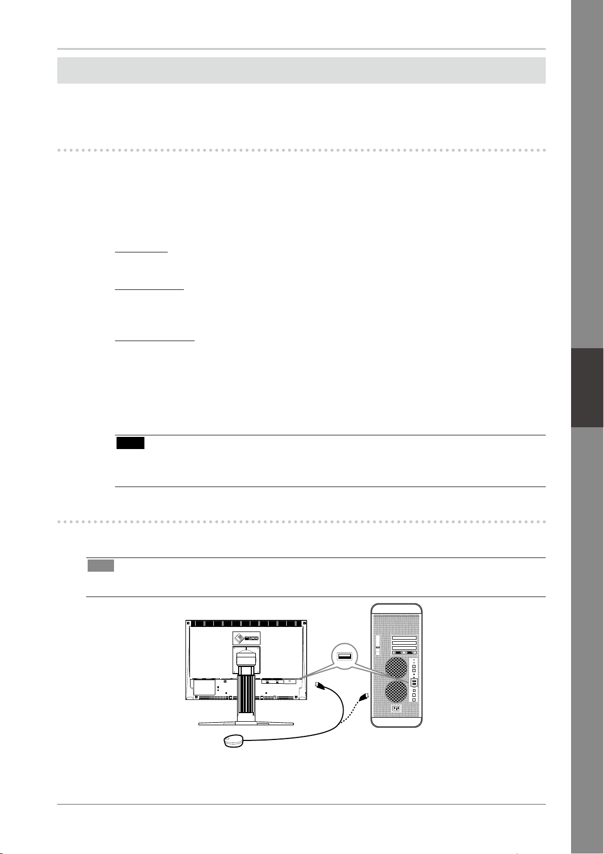
Connecting the measurement device
Connect an optional measurement device which you purchased separately.
Tips
Refer to the User’s Manual for the measurement device in regard to connection.
•
7
Page 10
How to calibrate the monitor
Startup ColorNavigator and calibrate the monitor. Follow the instructions displayed on the screen and in
the ColorNavigator Quick Reference.
For details, refer to the "ColorEdge ColorNavigator User’s Manual" on the EIZO LCD Utility Disk.
Note
When calibrating the monitor, the monitor and the PC must have had the power on for at least 30
•
minutes. Be sure to calibrate the monitor after the power has been turned on for 30 minutes or more.
Tips
For detailed information about calibration, visit http://www.eizo.com.
•
You can use the mode button on the front panel to switch the monitor to one of the four image
adjustment modes (sRGB mode, Custom mode, CAL mode, and EMU mode) suitable for the displayed
image.
No-Picture Problem
If no picture is displayed on the monitor even after the following remedial action is taken, contact your local
dealer.
1. Check the Power indicator.
Symptom Status Possible cause and remedy
No picture Power indicator does not light
up.
Power indicator lights blue. • Set high values for Gain RGB levels.
Power indicator lights orange.
• Check whether the power cord is correctly
connected.
• If the problem persists, turn off the monitor,
and then turn it on again a few minutes later.
• Press .
• Switch the input signal with
• Press a key on the keyboard or click the mouse.
• Turn on the PC.
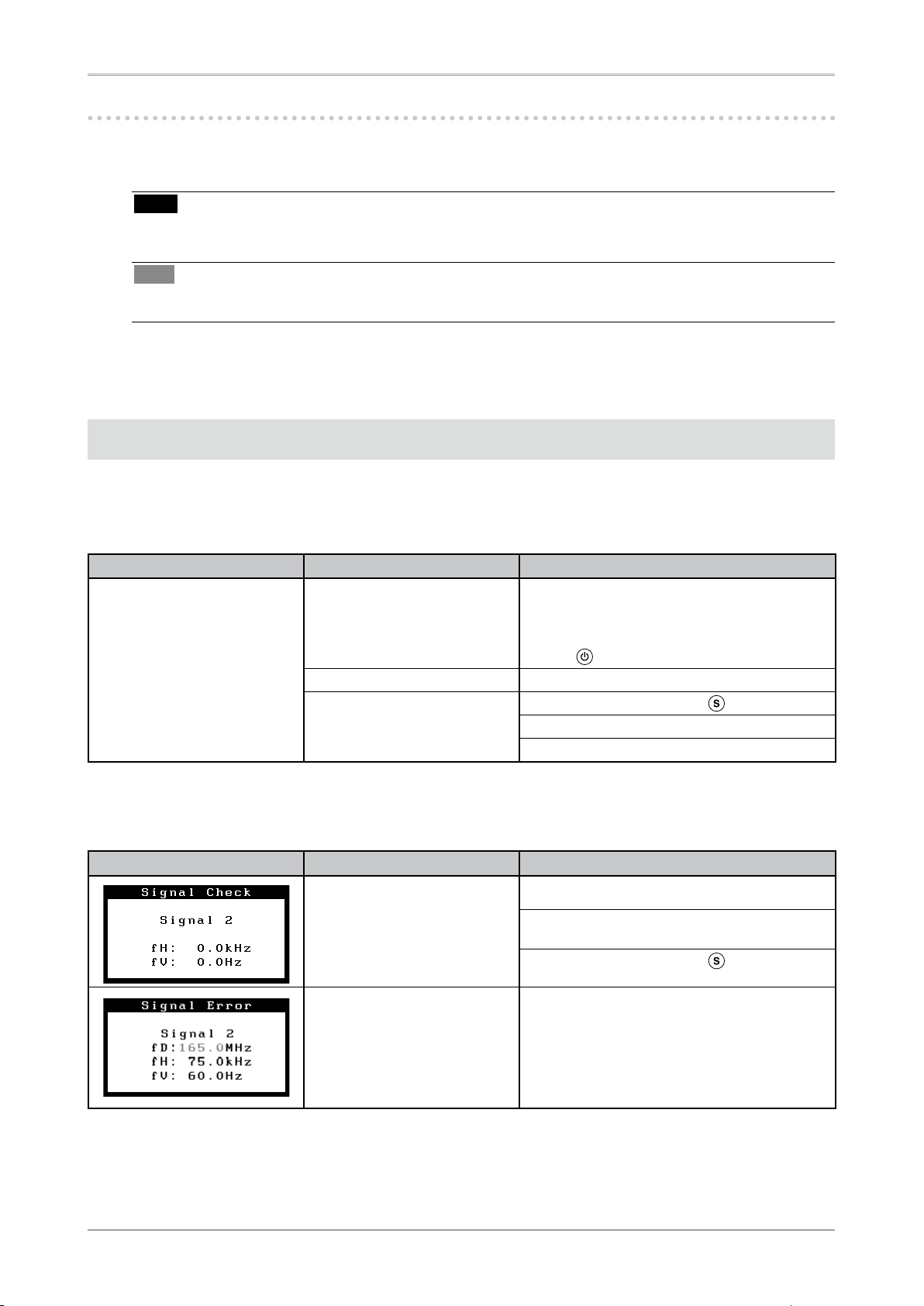
2. Check the error message that remains on the screen.
These messages appear when the input signal is incorrect even if the monitor is functioning.
Symptom Status Possible cause and remedy
The input signal is not received. • Check whether the PC is turned on.
• Check whether the signal cable is properly
connected to the PC.
• Switch the input signal with
The signal frequency is outside
the specification. Incorrect
signal frequency is shown in
red.
• Restart the PC.
• Change the mode to an appropriate mode
using the graphics board’s utility software.
Refer to the manual of the graphics board for
details.
.
.
8
Page 11
English
Français
中
文
Deutsch
Überprüfen des Verpackungsinhalts
Wenn Sie den Monitor aus der Verpackung nehmen, entfernen Sie zuerst die Zubehörteile, und heben Sie
anschließend den Monitor vorsichtig heraus.
Kontaktieren Sie bitte Ihren Händler, wenn Teile fehlen oder beschädigt sind.
Die Verpackung enthält folgende Teile.
Hinweis
•
Werfen Sie die Verpackung nicht weg (Schachtel und Schutzverpackung). Bewahren Sie sie an einem sicheren
Ort auf. Wenn das Gerät zur Reparatur eingesandt werden muss, wird die Verpackung wieder benötigt.
•
ColorNavigator-Kurzanleitung
•
Informationen zum Thema Recycling
Reinigungsset
„ScreenCleaner“
Analoges Signalkabel
(FD-C16)
Digitales Signalkabel
(FD-C39)
•
Installationshandbuch
(das vorliegende Handbuch)
•
Befestigungsschrauben
(M4 x 12, 4 Stck.)
•
CD-ROM mit EIZOs LCD Utility Disk
•
Kalibirierungssoftware
ColorNavigator
Abdeckhaube
Monitor
•
Benutzerhandbücher (im PDF-Format)
ColorEdge CG222W
ColorNavigator usw.
•
Beschränkte Garantie
•
VORSICHTSMASSNAHMEN
Netzkabel
EIZO USB-Kabel
(MD-C93)
Justagezer-
tifizierung
Justagezertifizierung
Dieses Blatt ist am Displayschutz des
„PAD-LCD“ LCD-Displays befestigt.
1
Page 12

Bedienelemente und Funktionen
15
A
B
16
98762 31 4 5
1010
11 12 1413
Die Tasten für die Bilddarstellung und verschiedene Einstellungen befinden sich an der Vorderseite des
Monitors, während sich sämtliche Anschlüsse an seiner Rückseite befinden. Die Namen und Funktionen der
Tasten und Anschlüsse werden im Folgenden beschrieben.
Justierungsmenü
(ScreenManager ® *)
1 Sensor Erkennt die Umgebungshelligkeit. Funktion zur Helligkeitsregulierung.
2 Taste zur Justiersperre Mit dieser Funktion werden die Tasten zum Beibehalten des justierten oder
3 Taste zur Auswahl des
Eingangssignals
4 Taste zur Modusauswahl Mithilfe dieser Taste wechseln Sie den Anzeigemodus.
5 Taste zur automatischen
Einstellung
6 Eingabetaste Zeigt das Justierungsmenü an, wählt ein Element im Menübildschirm und
7 Steuertasten
(Links, Unten, Oben, Rechts)
8 Netzschalter Zum Ein- und Ausschalten.
9 Betriebsanzeige
10
Öffnung für Diebstahlsicherung
11 Netzstecker Zum Anschließen an eine Netzsteckdose.
12 Signaleingänge DVI-I-Anschluss x 2
13 USB-Anschluss (hinten) Schließen Sie das USB-Kabel an, um die mitgelieferte Software verwenden
14 USB-Anschluss (seitlich) Stellt eine Verbindung zu einem USB-Peripheriegerät her.
15 Fuß Zum Einstellen der Höhe und Neigung des Bildschirms.
16 Kabelabdeckung Verdeckt die Anschlusskabel.
A Hinweise Das Gerät muss an eine ordnungsgemäß geerdete Steckdose angeschlossen
B Hinweise ACHTUNG Gefahr des elektrischen schlages. Rückwand nicht entfernen.
*
ScreenManager ® ist der Name des Justierungsmenüs von EIZO. (Informationen zur Verwendung von ScreenManager entnehmen Sie dem
Benutzerhandbuch auf der CD-ROM.)
Nähere Informationen finden Sie in der Betriebsanleitung auf der CD-ROM.
eingestellten Status gesperrt.
Schaltet zwischen den Signalen zweier angeschlossener PC um.
Stellt den Bildschirm automatisch ein (funktioniert nur beim Analogeingang).
speichert geänderte Werte.
Wählt ein Einstellungselement oder erhöht/reduziert justierte Werte erweiterter
Einstellungen mithilfe des Justierungsmenüs.
Zeigt den Betriebsstatus des Monitors an.
Blau: In Betrieb Orange: Energiesparmodus
Aus: Hauptstromversorgung getrennt
Blau blinkend (jeweils 2-fach): Beachten Sie, dass der Monitor (im CAL-Modus oder im
EMU-Modus) neu zu kalibrieren ist, wenn der Timer auf ColorNavigator eingestellt ist.
Kompatibel mit dem Kensington MicroSaver-Sicherheitssystem.
zu können. Informationen zur Verwendung der Software entnehmen Sie der
Benutzerhandbuch auf der CD-ROM.
werden.
2
Page 13

English
Français
中
文
Deutsch
Kabel anschließen
Schließen Sie den Monitor an den PC an. Schalten Sie den Monitor, den PC und alle externen Geräte aus, bevor Sie
die Kabel anschließen. Nähere Informationen finden Sie in der Betriebsanleitung auf der mitgelieferten CD-ROM.
Am PC anschließen
Am Monitor anschließen
Netzkabel
An Steckdose anschließen
Digitales/Analoges Signalkabel
Verbinden Sie Monitor und PC mithilfe eines passenden Signalkabels.
1
Ziehen Sie nach dem Anschließen der Kabel die Schrauben der Verbinder an, um ein
versehentliches Ausstecken zu verhindern.
Anschlüsse am Monitor kabel Anschlüsse am PC
DVI-I
DVI-I
Schließen Sie das USB-Kabel an, um die mitgelieferte Software verwenden zu können.
2
Am Monitor anschließen Am PC anschließen
[Analoges Signalkabel]
FD-C16 Analoge Verbindung
[Digitales Signalkabel]
FD-C39 Digitale Verbindung
USB-Kabel
Hinweis
• Das USB-Kabel ist für die Kalibrierung erforderlich. Verbinden Sie Monitor und PC mit dem
USB-Kabel.
3
Verbinden sie mithilfe des Netzkabels den Netzanschluss des Monitors mit einer
Steckdose.
Drücken Sie , um den Monitor einzuschalten.
4
Die Betriebsanzeige des Monitors leuchtet auf (blau).
Schalten Sie den PC ein.
5
Schalten Sie den PC ein.
Wenn kein Bild erscheint, ermitteln Sie mit Hilfe des Kapitels „Problem: Kein Bild“ die Ursache
dieses Problems.
Hinweis
•
Wenn sowohl PC als auch Monitor ausgeschaltet sind, ist die Stromversorgung für den Monitor
komplett unterbrochen, auch wenn das Netzkabel noch mit dem Monitor verbunden ist.
3
Page 14

Auflösung einstellen
Führen Sie die folgenden Schritte aus, wenn die Bildschirmauflösung nach dem Anschließen des Monitors an
den PC mangelhaft ist oder wenn Sie die Bildschimauflösung ändern möchten.
Empfohlene Bildschirmauflösung: 1680 Bildpunkte x 1050 Zeilen (60 Hz)
MacOS X
Wählen Sie im Apple-Menü die Option „Systemeinstellungen“.
1
Klicken Sie im Dialogfenster „Systemeinstellungen“ unter „Hardware“ auf „Monitore“.
2
Wählen Sie im angezeigten Dialogfenster die Registerkarte „Monitore“ und anschließend im Feld
3
„Auflösungen“ die gewünschte Bildschirmauflösung.
Die Bildschirmauflösung wird sofort auf den gewünschten Wert geändert. Wenn Sie mit dieser Auflösung
4
zufrieden sind, schließen Sie das Fenster.
Windows XP
Klicken Sie mit der rechten Maustaste irgendwo auf den leeren Desktop.
1
Wählen Sie im angezeigten Menü die Option „Eigenschaften“.
2
Klicken Sie im Dialogfenster „Eigenschaften von Anzeige“ auf die Registerkarte „Einstellungen“ und
3
wählen Sie dort unter „Anzeige“ die gewünschte „Bildschirmauflösung“.
Klicken Sie auf „OK“, um das Dialogfenster zu schließen.
4
Windows Vista
Klicken Sie mit der rechten Maustaste irgendwo auf den leeren Desktop.
1
Klicken Sie im angezeigten Menü auf „Anpassen“.
2
Klicken Sie im Dialogfenster „Systemsteuerung -> Anpassung“ auf „Anzeige“.
3
Klicken Sie im Dialogfenster „Anzeigeeinstellungen“ auf die Registerkarte „Monitor“ und wählen Sie
4
im Feld „Auflösung“ die gewünschte Bildschirmauflösung.
Klicken Sie auf „OK“.
5
Wenn ein Bestätigungsdialog erscheint, klicken Sie darin auf „Ja“.
6
Einstellung von Höhe und Winkel des Monitors
Winkel und Höhe des Monitors sind verstellbar.
Stellen Sie die für Ihren Arbeitsplatz optimale Höhe, den Winkel, sowie die Neigung und Drehung des
Bildschirms ein.
4
Page 15

English
Français
中
文
Deutsch
Installation der Haube
ACHTUNG
Tragen Sie den Monitor nicht mit angebrachter
Haube.
Beim Tragen des Monitors könnte die Haube abfallen
oder vom Gerät rutschen, wodurch es zu Verletzungen
oder einer Beschädigung des Geräts kommen könnte.
Schließen Sie die Abdeckung zum Öffnen/
Schließen, bis sie den Anschlag berührt.
Falls die Abdeckung nicht richtig geschlossen wird,
sind die Lüftungsschlitze abgedeckt, und der richtige
Luftfluss wird verhindert. Dadurch kann es zu
Überhitzen im Monitor kommen, was zu einem Brand,
Stromschlag oder einer Beschädigung des Geräts
führen kann.
Lieferumfang
Prüfen Sie, ob sich alle der folgenden Gegenstände in der Verpackung befinden.
Stellen Sie keine Gegenstände auf die Haube.
Falls die Haube abfällt oder vom Gerät rutscht oder
falls der Monitor umkippt, kann es zu Verletzungen
oder einer Beschädigung des Geräts kommen.
Drehen Sie den Monitor nicht in die HochformatPosition.
Anderenfalls könnte die Haube vom Gerät rutschen,
wodurch es zu Verletzungen oder einer Beschädigung
des Geräts kommen könnte.
Abdeckung zum Öffnen/Schließen
Obere Abdeckung
Linke Abdeckung
Haken
Metallverbindungsstück
Obere Abdeckung
Haken
Rechte Abdeckung
Montage der linken und rechten Haube
Montieren Sie die Hauben in Richtung der Pfeile, die auf den Einfügungsteilen der oberen Abdeckungen
der rechten und linken Haube markiert sind.
Halten Sie die linke und obere Abdeckung der linken Haube so, dass die
1
Antireflexionsbeschichtung nach innen zeigt.
Schließen Sie die obere und linke
2
Abdeckung an, indem Sie den Pfeil
) auf dem Einfügungsteil der oberen
(1
Abdeckung auf die beiden Striche im
Einfügungsschlitz der linken Abdeckung
ausrichten.
Schieben Sie die obere Abdeckung in
3
die von Pfeil (2 ) angezeigte Richtung.
Die Montage der linken Haube ist
abgeschlossen.
Montieren Sie die rechte Haube auf die gleiche Weise.
4
5
Page 16

Befestigen Sie die linke und die rechte Haube am Monitor.
Achten Sie darauf, die zweite Haube erst zu installieren, nachdem Sie die andere Haube sicher mit einem
Haken angebracht haben.
Befestigen Sie die Oberseite der linken Haube zuerst am
1
Monitor, und befestigen Sie dann die linke Seite der Haube
sicher, um die Haube am Monitor anzubringen.
Schieben Sie den Haken in die obere
2
Öffnung an der Haube (1) und schieben
Sie am Vorsprung an der Rückseite des
Monitors (2) entlang nach unten.
In die obere
Öffnung schieben
Befestigen Sie die rechte Haube auf die gleiche Weise.
3
Überprüfen Sie die Stellen
4
mit den Vertiefuungen an den
Verbindungsstücken, und führen Sie die
Verbindungsstücke in die rechte und linke
Haube ein, indem Sie jene Vertiefungen
auf die Vorsprünge (
rechten und linken Haube ausrichten.
) in den Nuten der
Befestigen Sie die Abdeckung zum Öffnen/Schließen an der
5
linken Haube.
Hinweis
Befestigen Sie die Abdeckung zum Öffnen/Schließen nicht an der rechten
•
Haube. Anderenfalls kann die Abdeckung nicht geschlossen werden.
Setzen Sie die Abdeckung zum Öffnen/Schließen auf die
6
Oberseite der linken Haube (ohne das Metallverbindungsstück
zu berühren), und zwar von vorne (1) nach hinten (2).
Schieben Sie die Abdeckung zum Öffnen/Schließen nach rechts
7
(3), bis sie den Anschlag am Metallverbindungsstück berührt.
Schieben Sie die Abdeckung zum Öffnen/Schließen bei der
8
Durchführung der Kalibrierung nach links, um den Sensor
anzubringen.
Hinweis
Die Abdeckung zum Öffnen/Schließen kann nicht auf die rechte
•
Abdeckung geschoben werden.
6
Page 17

English
Français
中
文
Deutsch
Messgerät
Beides möglich
Vorbereitung für die Kalibrierung des Monitors
Einzelheiten bezüglich des Kalibriervorgangs entnehmen Sie bitte dem ColorNavigator-Benutzerhandbuch
auf der CD-ROM.
Installation von ColorNavigator
Deinstallieren Sie alle Messtreiber, die auf Ihrem PC installiert sind.
1
Legen Sie die EIZO LCD Dienstprogramm-Disk in das CD/DVD-Laufwerk ein.
2
MacOS X
3
Klicken Sie auf das CD-ROM-Symbol am Desktop, und klicken Sie in dem daraufhin erscheinenden Fenster auf [Start Menu].
Windows XP
Es öffnet sich automatisch ein Menüfenster. Falls sich das Menüfenster nicht von selbst öffnet,
doppelklicken Sie bitte auf das „Launcher.exe“ -Symbol auf der CD-ROM.
Windows Vista
Wenn Sie Windows Vista verwenden, kann ein „User Account Control“ Dialogfenster nach dem
Anklicken des „Launcher.exe“ -Symbols erscheinen.
Klicken Sie in diesem Fall auf [Continue], um das Menü zu öffnen.
Klicken Sie auf „Install ColorNavigator“ im Anfangsbildschirm des EIZO LCD-
4
Dienstprogramms.
Befolgen Sie die Anleitungen, um die Instalaltion abzuschließen.
Hinweis
Der Messtreibre wird während der ColorNavigator-Installation automatisch installiert. Es ist
•
nicht erforderlich, den mit Ihrem Messgerät mitgelieferten Treiber zu installieren.
Anschließen des Messgeräts
Schließen Sie ein separat gekauftes Messgerät an.
Hinweis
Zusätzliche Hinweise zum Anschluss finden Sie im Benutzerhandbuch des Messgeräts.
•
7
Page 18

Kalibrierung des Monitors
Starten Sie den ColorNavigator und kalibrieren Sie den Monitor. Befolgen Sie die Anweisungen, die auf
dem Bildschirm und im ColorNavigator-Kurzanleitung angeführt werden.
Einzelheiten entnehmen Sie bitte dem „ColorEdge ColorNavigator-Benutzerhandbuch“ auf der
CD-ROM mit EIZOs LCD Utility Disk.
Hinweis
Bevor Sie den Monitor kalibrieren, müssen Monitor und PC bereits mindestens 30 Minuten
•
eingeschaltet gewesen sein. Vergewissern Sie sich, dass der Strom bereits mindestens 30 Minuten lang
eingeschaltet war, bevor Sie den Monitor kalibrieren.
Hinweis
Nähere Informationen über den Kalibriervorgang finden Sie auf http://www.eizo.com.
•
Mit der Modustaste an der Vorderseite des Monitors können Sie aus den vier Bildeinstellmodi (sRGB,
Custom, CAL und EMU) den für jedes einzelne Bild am besten geeigneten Modus auswählen.
Problem: Kein Bild
Wird auch nach dem Durchführen der nachfolgend vorgeschlagenen Lösungen kein Bild angezeigt, wenden Sie
sich an Ihren Fachhändler.
1. Prüfen Sie den Status der Betriebsanzeige.
Symptom Status Mögl. Ursache und Lösung
Kein Bild Anzeigenstatus: Aus. • Prüfen Sie, ob das Netzkabel richtig
Anzeigenstatus: Blau • Stellen Sie für Ermittle RGB-Pegel hohe Werte
Betriebsanzeigenstatus:
Orange
eingesteckt ist.
• Besteht das Problem weiterhin, schalten Sie
den Monitor aus und nach wenigen Minuten
wieder ein.
• Drücken Sie
ein.
• Wechseln Sie durch Drücken der Taste
Signaleingang.
• Drücken Sie eine Taste auf der Tastatur, oder
klicken Sie mit der Maus.
• Schalten Sie den PC ein.
.
2. Überprüfen Sie die Fehlermeldung auf dem Bildschirm.
Diese Meldungen werden angezeigt, wenn das Eingangssignal nicht ordnungsgemäß übertragen wird, der
Monitor jedoch korrekt funktioniert.
Symptom Status Mögl. Ursache und Lösung
Das Eingangsignal wird nicht
empfangen.
Die Signalfrequenz liegt nicht
im zulässigen Bereich. Die
falsche Signalfrequenz wir rot
angezeigt.
• Prüfen Sie, ob der PC eingeschaltet ist.
• Prüfen Sie, ob das Signalkabel ordnungsgemäß
am PC angeschlossen ist.
• Wechseln Sie durch Drücken der Taste
Signaleingang.
• Starten Sie den PC neu.
• Wechseln Sie mithilfe des zur Grafikkarte
gehörenden Dienstprogramms in einen
kompatiblen Modus. Weitere Informationen
hierzu entnehmen Sie dem Handbuch der
Grafikkarte.
den
den
8
Page 19

Contrôle du contenu de la boîte
English
Français
中
文
Deutsch
En enlevant le moniteur de son emballage, retirez d’abord les accessoires, puis soulevez doucement le moniteur
pour le sortir.
Contactez votre revendeur local si un article manque ou est endommagé.
La boîte doit comporter les éléments suivants.
Attention
•
Ne jetez pas l’emballage (boîte et emballages de protection). Conservez-le dans un endroit sûr. Vous en aurez
besoin si vous étiez amené à retourner l’appareil pour réparation.
•
Référence rapide de ColorNavigator
•
Informations sur le recyclage
Kit de nettoyage
« ScreenCleaner »
Câble de signal
analogique (FD-C16)
Câble de signal
numérique(FD-C39)
•
Manuel d’installation (ce manuel)
•
Vis de montage (M4 x 12, 4 pièces)
•
EIZO LCD Utility Disk (CD-ROM)
•
Logiciel d’étalonnage
ColorNavigator
Capot
Moniteur
•
•
Garantie limitée
•
PRECAUTIONS
Manuels d’utilisation au format PDF
ColorEdge CG222W
ColorNavigator etc.
Cordon
d’alimentation
Câble EIZO USB
(MD-C93)
Certification
du réglage
Certification du réglage
La présente feuille est jointe à la housse de
protection du panneau LCD « PAD-LCD ».
1
Page 20

Commandes et fonctions
15
A
B
16
98762 31 4 5
1010
11 12 1413
Les boutons d’affichage et de réglage sont disposés à l’avant du moniteur et les connecteurs à l’arrière. Vous
trouverez à la suite le nom et les fonctions des boutons et des connecteurs.
Menu Ajustage
(ScreenManager ® *)
1 Capteur Détecte la luminosité ambiante. Fonction BrightRegulator.
2 Touche de Verrouillage des
réglages
3 Touche de sélection du
signal d’entrée
4 Touche Mode Permet de changer le mode d’affichage.
5 Touche de réglage Auto Pour ajuster automatiquement l’écran. (entrée analogique uniquement)
6 Touche de validation Pour afficher le menu Ajustage, pour sélectionner un élément de l’écran de
7 Touches de commande
(Gauche, Bas, Haut, Droite)
8 Touche d’alimentation Pour mettre sous/hors tension.
9 Voyant d’alimentation Pour indiquer l’état de fonctionnement du moniteur.
10 Fente pour le verrouillage
de sécurité
11 Connecteur d’alimentation Permet de raccorder le connecteur d’alimentation.
12 Connecteurs de signal
d’entrée
13 Port USB (amont) Raccorde le câble USB pour utiliser le logiciel fourni. Consultez le manuel
14 Port USB (aval) Permet de raccorder un périphérique USB.
15 Pied Utilisé pour ajuster la hauteur et l’angle de l’écran du moniteur.
16 Enveloppe de câbles Protège les câbles du moniteur.
A Étiquettes de sécurité L’appareil doit être relié à une prise avec terre.
B Étiquettes de sécurité ATTENTION Risque de choc elestrique. Ne pas ouvrir.
*
ScreenManager ® est un alias choisi par EIZO pour le menu Ajustage. (Consultez le manuel d’utilisation sur le CD-ROM si vous désirez de plus amples
détails sur l’utilisation de ScreenManager.)
Pour en savoir plus, reportez-vous au manuel d’utilisation qui se trouve sur le
CD-ROM.
Cette fonction verrouille les touches pour maintenir l’état réglé ou défi ni
précédemment.
Pour commuter les signaux d’entrée de l’affichage lors de la connexion de 2 PC
au moniteur.
menu et sauvegarder les valeurs ajustées.
Pour sélectionner un élément d’ajustage ou augmenter/diminuer les valeurs
ajustées pour des ajustages avancés à l’aide du menu Ajustage.
Bleu : En fonctionnement Orange : Economie d’énergie Eteint : Hors tension
Bleu clignotant (2 énergie): Lorsque le minuteur est défini dans ColorNavigator,
indique qu’un nouveau calibrage est nécessaire (en mode CAL ou EMU).
Compatible avec le système de sécurité MicroSaver de Kensington.
Connecteur DVI-I x 2
d’utilisation inclus sur le CD-ROM pour savoir comment utiliser ce logiciel.
2
Page 21

Connexion des câbles
English
Français
中
文
Deutsch
Permet de connecter le moniteur au PC. Eteignez le moniteur, le PC et tous les périphériques avant de connecter
les câbles. Pour en savoir plus, reportez-vous au manuel d’utilisation qui se trouve sur le CD-ROM fourni.
Connexion au PC
Connexion au moniteur
Cordon
d’alimentation
Connexion à la prise
d’alimentation
1
2
Connectez le moniteur au PC à l’aide d’un câble de signal correspondant aux connecteurs.
Une fois que les connecteurs de câble sont connectés, serrez les vis des connecteurs pour assurer le
couplage.
Connecteurs du moniteur Câble Connecteurs du PC
Raccordez le moniteur au PC avec le câble USB.
Connexion au moniteur Connexion au PC
DVI-I
DVI-I
Câble USB
Câble de signal numérique/analogique
[Câble de signal analogique]
FD-C16 Connexion analogique
[Câble de signal numérique]
FD-C39 Connexion numérique
Attention
• Le câble USB est nécessaire pour le calibrage. Veillez à raccorder le moniteur et le PC avec le
câble USB.
Branchez le cordon d’alimentation dans une prise secteur et dans le connecteur
3
d’alimentation du moniteur.
Appuyez sur pour mettre le moniteur sous tension.
4
Le voyant d’alimentation du moniteur s’éclaire en bleu.
Mettez le PC sous tension.
5
L’image affichée apparaît. Si une image n’apparaît pas, consultez la sectio « Problème de nonaffichage d’images » pour savoir commentprocéder.
Remarque
•
Lorsque le PC et le moniteur sont éteints, l’alimentation du moniteur est entièrement coupée,
même si le cordon d’alimentation est encore connecté au moniteur.
3
Page 22

Réglage de la résolution
Si vous n’êtes pas satisfait de la résolution après avoir raccordé le moniteur au PC ou si vous souhaitez modifier
la résolution, conformez-vous à la procédure décrite à la suite.
Résolution recommandée : 1 680 points x 1 050 lignes (60 Hz)
MacOS X
Sélectionnez « System Preferences » dans le menu Apple.
1
Lorsque la boîte de dialogue « System Preferences » s’affiche, cliquez sur « Displays » pour « Hardware ».
2
Dans la boîte de dialogue figurant à l’écran, sélectionnez l’onglet « Display » et sélectionnez la résolution
3
souhaitée dans le champ « Resolutions ».
Votre sélection s’affiche immédiatement. Une fois la résolution souhaitée atteinte, fermez la fenêtre.
4
Windows XP
A l’aide de la souris, réalisez un clic droit sur n’importe quel point du bureau à l’exception des icônes.
1
Une fois le menu affiché, cliquez dans « Properties ».
2
Lorsque la boîte de dialogue « Display Properties » s’affiche, cliquez sur l’onglet « Settings » et sélectionnez
3
la résolution souhaitée pour « Screen resolution » dans « Display ».
Cliquez sur le bouton « OK » pour fermer la boîte de dialogue.
4
Windows Vista
A l’aide de la souris, réalisez un clic droit en n’importe quel point du bureau à l’exception des icônes.
1
Une fois le menu affiché, cliquez sur « Personalize ».
2
Dans la fenêtre « Personalization », cliquez sur « Display Settings ».
3
Dans la boîte de dialogue « Display Settings », sélectionnez l’onglet « Monitor » et choisissez la résolution
4
souhaitée dans le champ « Resolution ».
Cliquez sur le bouton « OK ».
5
Lorsque la boîte de dialogue de confirmation s’affiche, cliquez sur « Yes ».
6
Réglage de la hauteur et de l’inclinaison du moniteur
Il est possible de régler la hauteur et l’inclinaison du moniteur.
Ajustez la hauteur et l’angle de l’écran, inclinez et faites pivoter le moniteur jusqu’à obtenir des conditions de
travail optimales.
4
Page 23

Installation du capot
English
Français
中
文
Deutsch
ATTENTION
Ne transportez pas le moniteur avec son capot.
Lorsque vous transportez le moniteur, le capot peut
tomber ou glisser et entraîner ainsi des blessures ou
endommager l’appareil.
Refermez le panneau d’ouverture/fermeture
jusqu’à ce qu’il touche le taquet d’arrêt.
Si le panneau n’est pas refermé correctement, les fentes
de ventilation du moniteur seront obstruées et la
circulation d’air ne se fera pas correctement. Cela peut
provoquer une surchauffe à l’intérieur du moniteur
pouvant entraîner des incendies, chocs électriques et
dégâts de l’appareil.
Contenu de l’emballage
Vérifiez que tous les éléments indiqués ci-dessous sont inclus dans le carton d’emballage.
Ne placez aucun objet sur le capot.
Si le capot tombe ou glisse ou que le moniteur tombe,
cela peut entraîner des blessures ou endommager
l’appareil.
Ne faites pas pivoter le moniteur en position
portrait.
Cela pourrait faire glisser le capot et entraîner des
blessures ou endommager l’appareil
Panneau d’ouverture/fermeture
panneau supérieur
panneau gauche
Crochet
Pièce en métal
panneau supérieur
Crochet
panneau droit
Montez le capot gauche et le capot droit
Montez les capots dans la direction des flèches indiquées sur les insertions des panneaux supérieurs des
capots gauche et droit.
Tenez les panneaux gauche et supérieur du capot gauche de façon à ce que le film
1
antireflet soit à l’intérieur.
Raccordez le panneau supérieur et
2
le panneau gauche en alignant la
flèche (1
supérieur sur les deux lignes de la fente
d’insertion du panneau gauche.
) de l’insertion du panneau
Faites glisser le panneau supérieur dans
3
la direction de la flèche (2 ).
Le montage du capot gauche est
terminé.
Montez le capot droit de la même manière.
4
5
Page 24

Fixez les capots gauche et droit sur le moniteur
Veillez à installer le second capot uniquement après avoir fermement fixé le premier capot avec le crochet.
Fixez d’abord le haut du capot gauche sur le moniteur, puis
1
attachez correctement le côté gauche du capot afin de fixer le
capot sur le moniteur.
Introduisez le crochet dans l’orifice
2
supérieur du capot (1) puis faites-le
glisser vers le bas le long de la partie
saillante située à l’arrière du moniteur
(2).
Fixez le capot droit de la même manière.
3
Vérifiez l’emplacement des creux dans la
4
pièce et insérez la pièce dans les capots
gauche et droit en alignant ces creux
sur les saillies (
capots droit et gauche.
) dans les rainures des
Insérer dans le
trou supérieur
Fixez le panneau d’ouverture/fermeture sur le capot gauche.
5
Attention
Ne fixez pas le panneau d’ouverture/fermeture sur le capot droit. Cela
•
empêcherait le panneau de se fermer.
Placez le panneau d’ouverture/fermeture sur le haut du capot
6
gauche (sans entrer en contact avec la pièce de métal) de
l’avant (1) vers l’arrière (2).
Faites glisser le panneau d’ouverture/fermeture vers la droite (3)
7
jusqu’à ce qu’il touche le taquet d’arrêt sur la pièce de métal.
Lors de l’exécution du calibrage, faites glisser le panneau
8
d’ouverture/fermeture vers le gauche afin de fixer le capteur.
Attention
Le panneau d’ouverture/fermeture ne glisse pas sur le panneau droit.
•
6
Page 25

Appareil de mesure
L’un ou l’autre est
OK
English
Français
中
文
Deutsch
Préparez le moniteur pour le calibrage
Pour plus d’informations sur la procédure de calibrage, reportez-vous au Manuel d’utilisation de
ColorNavigator fourni sur le CD-ROM.
Installer ColorNavigator
Désinstallez tout pilote de mesurage installé sur le PC.
1
Insérez le disque d’utilitaires EIZO LCD dans le lecteur de CD/DVD du PC.
2
MacOS X
3
Cliquez sur l’icône du CD-ROM sur le bureau, puis cliquez sur [Start Menu] dans la fenêtre affi
chée.
Windows XP
Un menu doit apparaître automatiquement. Si ce n’est pas le cas, double-cliquez sur le fi chier
« Launcher.exe » dans l’arborescence du CD-ROM.
Windows Vista
Si vous utilisez Windows Vista, une boîte de dialogue « User Account Control » peut apparaître en
cliquant sur l’icône « Launcher.exe ». Dans ce cas, cliquez sur [Continue] pour ouvrir le menu.
Cliquez sur « Install ColorNavigator » dans l’écran initial des utilitaires EIZO
4
LCD.
Suivez les instructions pour terminer l’installation.
Attention
Le pilote de mesure est automatiquement installé pendant l’installation de ColorNavigator. Il
•
n’est pas nécessaire d’installer le pilote fourni avec votre appareil de mesure.
Raccordement de l’appareil de mesure
Raccordez un dispositif de mesure en option que vous vous serez procuré séparément.
Remarque
Consultez le manuel d’utilisation de l’appareil de mesure pour plus de détails concernant le raccordement.
•
7
Page 26

Calibrer le moniteur
Démarrez ColorNavigator et étalonnez le moniteur. Suivez les instructions à l’écran ainsi que les
instructions du Guide de Référence rapide de ColorNavigator.
Pour plus d’informations, reportez-vous au « Manuel d’utilisation de ColorEdge ColorNavigator »,
fourni sur le CD-ROM d’utilitaires EIZO LCD.
Attention
Pour pouvoir calibrer le moniteur, ce dernier ainsi que le PC doivent être sous tension depuis au moins
•
30 minutes. Assurez-vous de calibrer le moniteur en respectant ce délai minimum de 30 minutes.
Remarque
Pour en savoir plus sur le calibrage, consultez l’adresse Internet suivante : http://www.eizo.com.
•
Vous pouvez utiliser le bouton Mode situé à l’avant du panneau pour commuter le moniteur sur l’un des
quatre modes de réglage d’image (mode sRGB, mode Custom (personnalisé), mode CAL et mode EMU)
approprié à l’image affichée.
Problème de non-affichage d’images
Si aucune image ne s’affiche sur le moniteur même après avoir utilisé les solutions suivantes, contactez votre
revendeur local.
1. Vérifiez le voyant d’alimentation.
Symptôme Etat Cause possible et solution
Aucune image Le voyant ne s’allume pas. • Le voyant s’allume en bleu.
• Si le problème persiste, mettez le moniteur
hors tension pendant quelques minutes, puis
remettez-le sous tension.
• Appuyez sur .
Le voyant s’allume en bleu. • Augmentez le niveau de la valeur de réglage
RGB pour le réglage [Gain].
Le voyant d’alimentation
s’allume en orange.
• Changez le signal d’entrée en appuyant sur
• Appuyez sur une touche du clavier ou cliquez
avec la souris.
• Mettez le PC sous tension.
2. Vérifiez le message d’erreur qui apparaît à l’écran.
Ces messages s’affichent lorsque le signal d’entrée est incorrect même si le moniteur fonctionne correctement.
Symptôme Etat Cause possible et solution
Le signal d’entrée n’est pas
reçu.
• Vérifiez si le PC est sous tension.
• Vérifiez si le câble de signal est correctement
connecté au PC.
• Changez le signal d’entrée en appuyant sur
.
.
La fréquence du signal est en
dehors de la spécification. La
fréquence de signal incorrecte
est indiquée en rouge.
• Redémarrez le PC.
• Passez en un mode approprié à l’aide du
logiciel utilitaire de la carte vidéo. Consultez le
manuel de la carte vidéo pour de plus amples
détails.
8
Page 27

检查包装内容
English
Français
中
文
Deutsch
拆下显示器的包装时,请先拿开附件,然后再轻轻提起显示器。
如果发现任何物品缺失或损坏,请与您当地的经销商联系。
包装中包括以下物品。
注意
•
请勿丢弃包装(箱子或保护性包装)。将它放在安全的地方。设备送交维修时将需要用到它。
•
ColorNavigator快速参考
•
回收信息
清洗套餐
“ScreenCleaner”
模拟信号电缆
(FD-C6)
数字信号电缆
(FD-C39)
•
设定手册(本手册)
•
安装螺丝(M4x2,4pcs)
•
EIZOLCDUtilityDisk(光盘)
•
测定软件
ColorNavigator
遮光板
显示器
•
用户手册(PDF格式)
ColorEdgeCG222W
ColorNavigator 等
EIZOUSB 电缆
(MD-C93)
•
调节认证
•
预防措施
电源线
调节认证
调节认证
此表单附在“PAD-LCD”液晶显示屏的
防护垫上。
Page 28

控制和功能
15
A
B
16
98762 31 4 5
1010
11 12 1413
显示和调整按钮位于显示器正面,连接器位于后部。按钮与连接器的名称及功能如下所述:
调整菜单
(ScreenManager® *)
传感器 探测周围亮度。BrightRegulator功能。
如需有关详细信息,请参阅光盘上的“用户手册”。
2 调整锁定按钮 此功能可锁定按钮以保持调整后的状态或设定后的状态。
3 输入信号选择按钮 当两个个人计算机连接在显示器上时,可用此按钮切换显示的输入信号。
4 模式按钮 可切换显示模式。
5 自动调节按钮 自动调节屏幕到合适状态。(仅限模拟输入)
6 确认按钮 显示调整菜单,确定菜单屏幕上的某个项目,并保存已调整的值。
7 控制按钮(左、下、上、右) 选择调整项目,或增加/降低利用调整菜单进行高级调整时的已调整值。
8 电源按钮 打开或关闭电源。
9 电源指示器 指示显示器的运行状态。
蓝色:运行中橙色:省电状态熄灭:电源关闭
闪烁蓝光:在为ColorNavigator设置计时器时,通知需要进行重新校准(针对
CAL模式或EMU模式)。
0
安全锁插槽 符合 Kensington的防盗锁安全系统。
电源连接器 连接电源连接器。
2
输入信号连接器 DVI-I连接器x2
3 USB端口(上) 使用软件时,用 USB电缆连接。关于如何使用此软件,请参考光盘上的用户手册。
4 USB端口(下) 连接外接 USB设备。
5
底座 用于调整显示器屏幕的高度和角度。
6
电缆固定器 固定显示器电缆。
A 警告声明 这设备必须连接至接地主插座。
B 警告声明 小心 有触电的风险。请勿打开。
*ScreenManager®是调整菜单的 EIZO别称。(关于如何使用 ScreenManager,请参考光盘中的用户手册。)
2
Page 29

连接电缆
English
Français
中
文
Deutsch
将显示器连接到计算机。在连接电缆之前,请关闭显示器、计算机及所有外围设备。如需有关详细信息,请参
阅所提供的光盘上包含的“用户手册”。
连接计算机
连接显示器
电源线
连接电源插座
数字信号电缆/模拟信号电缆
用一根与连接器匹配的信号电缆连接显示器和个人计算机。
1
连接到电缆连接器后,请拧紧连接器的螺钉,使配合紧密。
显示器上的连接器 电缆 个人计算机上的连接器
DVI-I
DVI-I
使用 USB电缆连接显示器和计算机。
2
连接显示器 连接计算机
USB电缆
[ 模拟信号电缆 ]
FD-C6模拟连接
[ 数字信号电缆 ]
FD-C39数字连接
注意
•进行校准时需要 USB电缆。请务必使用 USB电缆连接。
将电源线插头插入电源插座和显示器上的电源连接器。
3
按 打开显示器。
4
显示器电源指示器亮起蓝色。
将个人计算机开机。
5
屏幕图像出现。
如果无法出现图像,请参考“无图片的问题”以获得帮助。
注意
•
在关闭计算机与显示器之后,尽管电源线仍然与显示器相连,但显示器电源已被完全切断。
3
Page 30

设置分辨率
在显示器与个人计算机相连之后,如果发现分辨率不合适,或需要更改分辨率时,请按照以下步骤操作。
建议分辨率:1680点x1050行(60Hz)
MacOSX
从Apple菜单中选择“系统预置”。
1
显示“系统预置”对话框时,单击“硬件”中的“显示器”。
2
在显示的对话框中,选择“显示器”选项卡并在“分辨率”区域选择需要的分辨率。
3
您的选择将会即刻反应出来。在您满意所选定的分辨率时,关闭窗口。
4
WindowsXP
在桌面(除图标之外)任意位置单击鼠标右键。
1
从显示的菜单中单击“属性”。
2
出现“显示属性”对话框时,单击“设置”选项卡并在“显示”下为“屏幕分辨率”选择所需的分辨率。
3
单击“确定”按钮关闭对话框。
4
WindowsVista
在桌面(除图标之外)任意位置单击鼠标右键。
1
从显示的菜单中单击“个性化”。
2
在“个性化”窗口中单击“显示设置”。
3
在“显示设置”对话框中选择“显示器”选项卡并在“分辨率”区域选择需要的分辨率。
4
单击“确定”按钮。
5
在确认对话框显示时,单击“是”。
6
调整显示器的高度与角度
显示器的高度与角度可以调整。
调整屏幕的高度与角度,并将屏幕倾斜和旋转到最佳工作位置。
4
Page 31

遮光板的安装
English
Français
中
文
Deutsch
注意
请勿在安装了遮光板的状态下移动显示器。
在移动中可能会发生遮光板的脱落导致人员伤害或设
备损坏。
请将遮光板的开合板闭合至碰到挡块的位置。
如果没有充分闭合,会堵塞显示器上的通风孔,妨碍
正常的空气流通。可能会 因此造成显示器内部高温,
导致火灾、触电和故障等事故。
包装内容
请检查包装盒中是否包含下列物品。如果缺少物品,或物品存在损坏现象,请与您所在地的经销商联系。
请勿在遮光板上放置物品。
可能会发生遮光板的坠落或显示器的翻倒,导致人员
伤害或设备损坏。
请勿竖起显示器。
可能会发生遮光板的脱落,导致人员伤害或设备损坏。
开合板
顶板
左侧板
固定钩
左右遮光板的组装
请按照左右遮光板(顶板)嵌入部分指示的箭头方向进行组装。
握住左侧遮光板的左侧板及顶板,使贴有防反射膜的一面向内。
1
将顶板嵌入部分箭头(1 )的位置对
2
准左侧板的嵌入槽(双线记号),垂直
嵌入。
固定用金属零件
顶板
固定钩
右侧板
顶板沿着箭头(2 ) 方向滑动。
3
左遮光板组装完成。
右遮光板按照相同的方法进行组装。
4
5
Page 32

将左右遮光板安装在显示器上
请在将一侧的遮光板用固定钩确实固定后,再安装另外一侧的遮光板。
左遮光板从显示器的上部开始安装,然后从侧面确实嵌入左侧
1
板,以便将遮光板固定在显示器上。
将挂钩插入遮光板(1)上部的孔中,并
2
沿着显示器(2)背部的凸出物向下滑
动。
右遮光板按照相同的方法安装。
3
确认固定用金属零件凹槽的位置,将固
4
定用金属零件的凹槽对准左右遮光板槽
的突出部分 ( 的位置 )并嵌入。
嵌入上侧的孔
将开合板安装在左遮光板上。
5
注意
•如果将开合板安装在右遮光板上,开合板将无法闭合。
按照从前 (1)到后 (2)的顺序将开合板覆盖在左遮光板
6
上部(无固定用金属件的部分)。
将开合板向右滑动闭合 (3),直到碰到固定用金属件的挡块。
7
进行校准时,将开 / 合盖滑动到左侧,以安装传感器。
8
注意
•开合板无法向右遮光板侧滑动。
6
Page 33

测定仪
二者均可
English
Français
中
文
Deutsch
显示器校准的准备工作
如需有关校准步骤的详细信息,请参阅光盘上的 ColorNavigator用户手册。
ColorNavigator的安装
已经安装了传感器附带的驱动程序时,请将该驱动程序卸载
1
将 EIZOLCD附带的实用光盘插入计算机的 CD/DVD驱动器。
2
MacOSX
3
单击桌面上的CD-ROM图标,然后在显示的窗口中单击[StartMenu](开始菜单)。
WindowsXP
将自动打开一个菜单。如果没有自动打开菜单,则双击CD-ROM中的“Launcher.exe”图标。
WindowsVista
使用WindowsVista时,单击“Launcher.exe”图标,此时可能出现“UserAccountControl”(用
户帐户控制)对话框。在这种情况下,单击[Continue](继续)以打开菜单。
画面显示 EIZOLCD实用启动画面,点击“InstallColorNavigator”,遵循画面
4
的指示进行安装。
注意
•如果安装了“ColorNavigator”,各种测定仪的驱动程序也将同时被安装。因此没有安装测定仪
附带软件的必要。
测定仪的连接
连接您单独购买的可选的测量设备。
注意
•有关测定仪的连接,请参照测定仪的用户使用手册。
7
Page 34

校准的实行
启动ColorNavigator并校准显示器。按照屏幕上与 ColorNavigator快速参考中显示的说明进行操作。
如需有关详细信息,请参阅 EIZOLCD实用程序光盘上的“ColorEdgeColorNavigator用户手册”。
注意
•校准显示器时,显示器与计算机必须已经通电至少 30分钟。请确保在通电30分钟及更长时间之后
校准显示器。
注意
•如需有关校准的详细信息,请访问http://www.eizo.com。
您可以使用前面板上的模式按钮来将显示器切换到四种图像调整模式(sRGB 模式、自定义模式、CAL
模式及EMU模式)中的一种,以适合所显示的图像。
无图片的问题
若已使用建议的修正方法后仍然无画面显示,请与您所在地的经销商联系。
.检查电源指示器。
症状 状态 原因和补救措施
无图片 电源指示器不亮。 •检查电源线是否已正确连接。
•如果问题仍未被解决,请关闭显示器,几分钟
后再打开。
•按 。
电源指示器点亮(蓝色)。 •将RGB增益级别设置为高值。
电源指示器点亮(橙色)。
•用 切换输入信号。
•按键盘上的某个键,或单击鼠标。
•将个人计算机开机。
2.查看屏幕上的出错信息。
即使显示器功能正常,当输入信号不正确时,这些信息仍会出现。
症状 状态 原因和补救措施
输入信号未收到。 •检查个人计算机是否已开机。
信号频率超出规定范围。错误的
信号频率会以红色显示。
•检查信号线是否已正确连接到个人计算机。
•用 切换输入信号。
•重新启动计算机。
•使用图形卡的实用程序软件将模式改变到某个
适当的模式。详情请参考图形卡的使用说明。
8
Page 35

Hinweise zur Auswahl des richtigen Schwenkarms für Ihren Monitor
Dieser Monitor ist für Bildschirmarbeitsplätze vorgesehen. Wenn nicht der zum Standardzubehör gehörige
Schwenkarm verwendet wird, muss statt dessen ein geeigneter anderer Schwenkarm installiert werden. Bei
der Auswahl des Schwenkarms sind die nachstehenden Hinweise zu berücksichtigen:
Der Standfuß muß den nachfolgenden Anforderungen entsprechen:
a) Der Standfuß muß eine ausreichende mechanische Stabilität zur Aufnahme des Gewichtes vom
Bildschirmgerät und des spezifizierten Zubehörs besitzen. Das Gewicht des Bildschirmgerätes und des
Zubehörs sind in der zugehörenden Bedienungsanleitung angegeben.
b)Die Befestigung des Standfusses muß derart erfolgen, daß die oberste Zeile der Bildschirmanzeige nicht
höher als die Augenhöhe eines Benutzers in sitzender Position ist.
c) Im Fall eines stehenden Benutzers muß die Befestigung des Bildschirmgerätes derart erfolgen, daß die
Höhe der Bildschirmmitte über dem Boden zwischen 135 – 150 cm beträgt.
d)Der Standfuß muß die Möglichkeit zur Neigung des Bildschirmgerätes besitzen (max. vorwärts: 5°, min.
nach hinten ≥ 5°).
e) Der Standfuß muß die Möglichkeit zur Drehung des Bildschirmgerätes besitzen (max. ±180°). Der
maximale Kraftaufwand dafür muß weniger als 100 N betragen.
f) Der Standfuß muß in der Stellung verharren, in die er manuell bewegt wurde.
g) Der Glanzgrad des Standfusses muß weniger als 20 Glanzeinheiten betragen (seidenmatt).
h)Der Standfuß mit Bildschirmgerät muß bei einer Neigung von bis zu 10° aus der normalen aufrechten
Position kippsicher sein.
Hinweis zur Ergonomie :
Dieser Monitor erfüllt die Anforderungen an die Ergonomie nach EK1-ITB2000 mit dem Videosignal,
1680 × 1050 , Digital Eingang und mindestens 60,0 Hz Bildwiederholfrequenz, non interlaced. Weiterhin
wird aus ergonomischen Gründen empfohlen, die Grundfarbe Blau nicht auf dunklem Untergrund zu
verwenden (schlechte Erkennbarkeit, Augenbelastung bei zu geringem Zeichenkontrast.)
„Maschinenlärminformations-Verordnung 3. GPSGV:
Der höchste Schalldruckpegel beträgt 70 dB(A) oder weniger gemäss EN ISO 7779“
Copyright© 2008 EIZO NANAO CORPORATION All rights reserved.
No part of this manual may be reproduced, stored in a retrieval system, or transmitted, in any form or by any
means, electronic, mechanical, or otherwise, without the prior written permission of EIZO NANAO CORPORATION.
EIZO NANAO CORPORATION is under no obligation to hold any submitted material or information confidential
unless prior arrangements are made pursuant to EIZO NANAO CORPORATION’s receipt of said information.
Although every effort has been made to ensure that this manual provides up-to-date information, please note that
EIZO monitor specifications are subject to change without notice.
Apple, Macintosh and Mac OS are registered trademarks of Apple Inc.
Windows is a registered trademark of Microsoft Corporation.
ColorNavigator is a trademark of EIZO NANAO CORPORATION.
ColorEdge and EIZO are registered trademarks of EIZO NANAO CORPORATION in Japan and other countries.
Page 36

EIZO NANAO CORPORATION
153 Shimokashiwano, Hakusan, Ishikawa 924-8566 Japan
Phone: +81 76 277 6792 Fax:+81 76 277 6793
EIZO NANAO TECHNOLOGIES INC.
5710 Warland Drive, Cypress, CA 90630, U.S.A.
Phone: +1 562 431 5011 Fax: +1 562 431 4811
EIZO EUROPE AB
Lovangsvagen 14 194 61, Upplands Väsby, Sweden
Phone: +46 8 594 105 00 Fax: +46 8 590 91 575
EIZO NANAO AG
Moosacherstrasse 6, Au CH - 8820 Wädenswil, Switzerland
Phone: +41-0-44 782 24 40 Fax: +41-0-44 782 24 50
This document is printed on recycled chlorine free paper.
http://www.eizo.com
1st Edition-February, 2008 Printed in Japan.
00N0L408A1
(U.M-SUCG222W-4)
 Loading...