

Page 1
LCD Monitor integrated
Windows-based Terminal
Touch Panel
LCD Monitor integrated
Windows-based Terminal
For Microsoft Windows CE 2.12
Version C
Please confirm the version of the software built in eClient, and refer to
the suited User's Manual (Refer to the User's Manual Version List on
next page).
This is the manual for the following software version.
*
Microsoft Windows CE:
*
Microsoft Terminal Server Client: Ver.5.60 or later
*
ICA Client:
Ver.6.30 [Build 1078] or later
2.12 Rev.3.53 or later
Page 2

User’s Manual Version List
A handling description changes with versions of the software built in eClient. Please
refer to below.
NOTE
• The version of software built in eClient can be checked with a [System]-[ICA] tab of
[Terminal Properties].
OS: Microsoft Windows CE 2.12
Software
Manual Terminal Server
C
(This Manual)
B 2.12 Rev.3.51 or later Version 5.60 or later
A 2.12 Rev.3.50 or later Version 5.51 or later
Microsoft Windows CE
2.12 Rev.3.53 or later Version 5.60 or later
Microsoft
Windows
[Build1078] or later
[Build992] or later
[Build992] or later
ICA Client
Software
Version 6.30
Version 6.20
Version 6.20
Page 3
English
p
SAFETY SYMBOLS
This manual uses the safety symbols below. They denote critical information. Please read them
carefully.
WARNING
Failure to abide by the information in a WARNING may result in serious injury and
can be life threatening.
CAUTION
Failure to abide by the information in a CAUTION may result in moderate injury
and/or property or product damage.
Indicates a prohibited action.
Indicates to ground for safety.
Copyright© 2002-2003 EIZO NANAO CORPORATION All rights reserved. No part of this
manual may be reproduced, stored in a retrieval system, or transmitted, in any form or by any
means, electronic, mechanical, or otherwise, without the prior written permission of Eizo Nanao
Corporation.
Eizo Nanao Corporation is under no obligation to hold any submitted material or information
confidential unless
said information. Although every effort has been made to ensure that this manual provides upto-date information, please note that EIZO monitor specifications are subject to change without
notice.
ENERGY STAR is a U.S. registered mark.
Apple and Macintosh are registered trademarks of Apple Computer, Inc.
VGA is a registered trademark of International Business Machines Corporation.
DPMS is a trademark and VESA is a registered trademark of Video Electronics Standards
Association.
Windows is a registered trademark of Microsoft Corporation.
ScreenManager and PowerManager are trademarks of Eizo Nanao Corporation.
FlexScan and EIZO are registered trademarks of Eizo Nanao Corporation.
As an ENERGY STAR
product meets the ENERGY STAR guidelines for energy efficiency.
rior arrangements are made pursuant to Eizo Nanao Corporation's receipt of
®
Partner, Eizo Nanao Corporation has determined that this
3
Page 4

English
TABLE OF CONTENTS
1. INTRODUCTION ..................................................................................... 5
1-1. General Description ......................................................................................5
1-2. Features ........................................................................................................6
1-3. Package Contents..........................................................................................6
1-4. Controls & Connectors ................................................................................7
1-5. Overview ......................................................................................................9
2. CONNECTING THE eClient.................................................................. 10
2-1. Setting up the eClient..................................................................................10
2-2. Connecting the eClient................................................................................11
3. SETTING UP THE eClient .................................................................... 13
3-1. WBT Setup Wizard .....................................................................................13
3-2. Dial-Up Connection (531L/531LT-GR only)...............................................27
4. ADDING & CHANGING A CONNETION NAME................................... 34
4-1. Adding a Connection Name........................................................................34
4-2. Deleting a Connection ................................................................................52
4-3. Editing a Connection ..................................................................................53
4-4. Setting an Autostart Connection.................................................................55
5. LOGON & LOGOFF.............................................................................. 56
5-1. Logon to a WTS .........................................................................................56
5-2. Logoff from the WTS..................................................................................59
6. USING THE TERMINAL PROPERTIES ................................................ 61
6-1. General Information & Reset to Default ....................................................61
6-2. Input Devices Settings .................................................................................63
6-3. Colors & Power Save Settings.....................................................................68
6-4. Network Settings ........................................................................................70
6-5. Printer Settings............................................................................................73
6-6. Dial-Up (PPP) Connection Settings (531L/531LT-GR only)........................76
6-7. ICA Settings................................................................................................77
6-8. Product Information, Security, & Updating Software .................................80
7. PRACTICAL SETUP............................................................................. 87
8. TROUBLESHOOTING........................................................................... 92
9. CLEANING............................................................................................ 94
10. SPECIFICATIONS............................................................................... 96
11. REFERENCE..................................................................................... 100
11-1. Attaching an Arm Stand .........................................................................100
INDEX ..................................................................................................... 102
TABLE OF CONTENTS
4
Page 5
1. INTRODUCTION
g
Thank you very much for purchasing the EIZO eClient 530L/531L/531LT-GR.
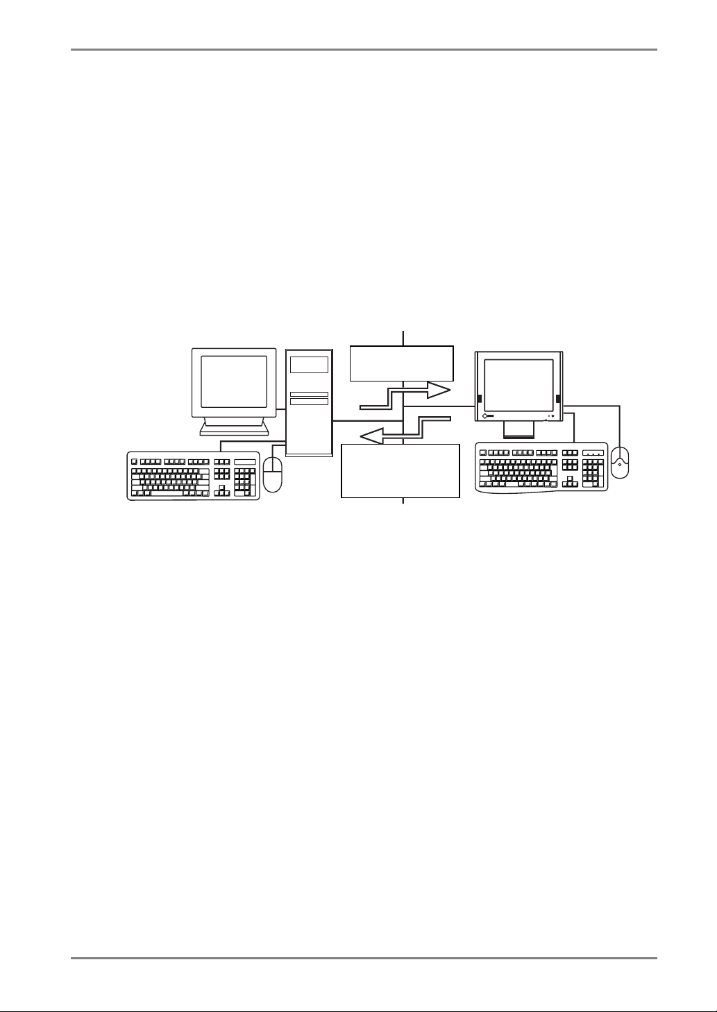
1-1. General Description
The eClient is a terminal which displays applications on a Windows Terminal Server
(WTS) or a web site and conveys input by a keyboard or a mouse to the WTS. To
operate the eClient, please connect it to a WTS with Microsoft Window NT Terminal
Server Edition or Windows 2000 Server / Advanced Server / Datacenter Server.
Windows Terminal Server (WTS)
Output data of
English
eClient
Input data from
keyboard/mouse
(stylus)
· Operation of applications
· Stora
e of data
· Display data
· Operation by keyboard/mouse
(stylus)
1. INTRODUCTION
5
Page 6

English
1-2. Features
• Lower TCO*
*TCO (Total Cost of Ownership)
Expense for managing and administrating computer systems.
• Saves Space and Power Consumption
• Less Heat, Less Noise
• 531L/531LT-GR
* Serial Port for Modem/PDA (*Hayes AT Compatible Modem Supported)
* Portrait resolution supported
[In use of the Citrix ICA Client (ICA)]
• 531LT-GR
* A Touch Panel and a Stylus Provided
1-3. Package Contents
Please contact your local dealer for assistance if any of the listed items are missing or
damaged. Please make sure that all the listed items are in the package.
• eClient 530L/531L/531LT-GR
• Mouse
• Power Cord
• Screw (M4 x 12 mm) x 4
• User’s Manual
• Stickers of the Brightness Control Guide
• Stylus (531LT-GR only)
NOTE
• We recommend that you retain the original packing materials in case of future need.
• A keyboard is not included. It must be purchased separately.
• Key combinations on the keyboard can adjust brightness (see page 69). Key
combinations for an adjustment are presented on the stickers. Please apply them
for your convenience.
Please use the enclosed mouse. Eizo Nanao Corporation will no be held responsible for
accident or damage caused by the use of a mouse manufactured by other companies.
6 1. INTRODUCTION
Page 7

1-4. Controls & Connectors
Front
English
(1) (2)
(1) Power Switch
(2) Power Indicator
Power Indicator Unit
Green Operation
Screen saver mode
Yellow Power save mode
NOTE
• When turning off/on the unit, leave the unit off for a few seconds before turning
it on again.
1. INTRODUCTION
7
Page 8
English
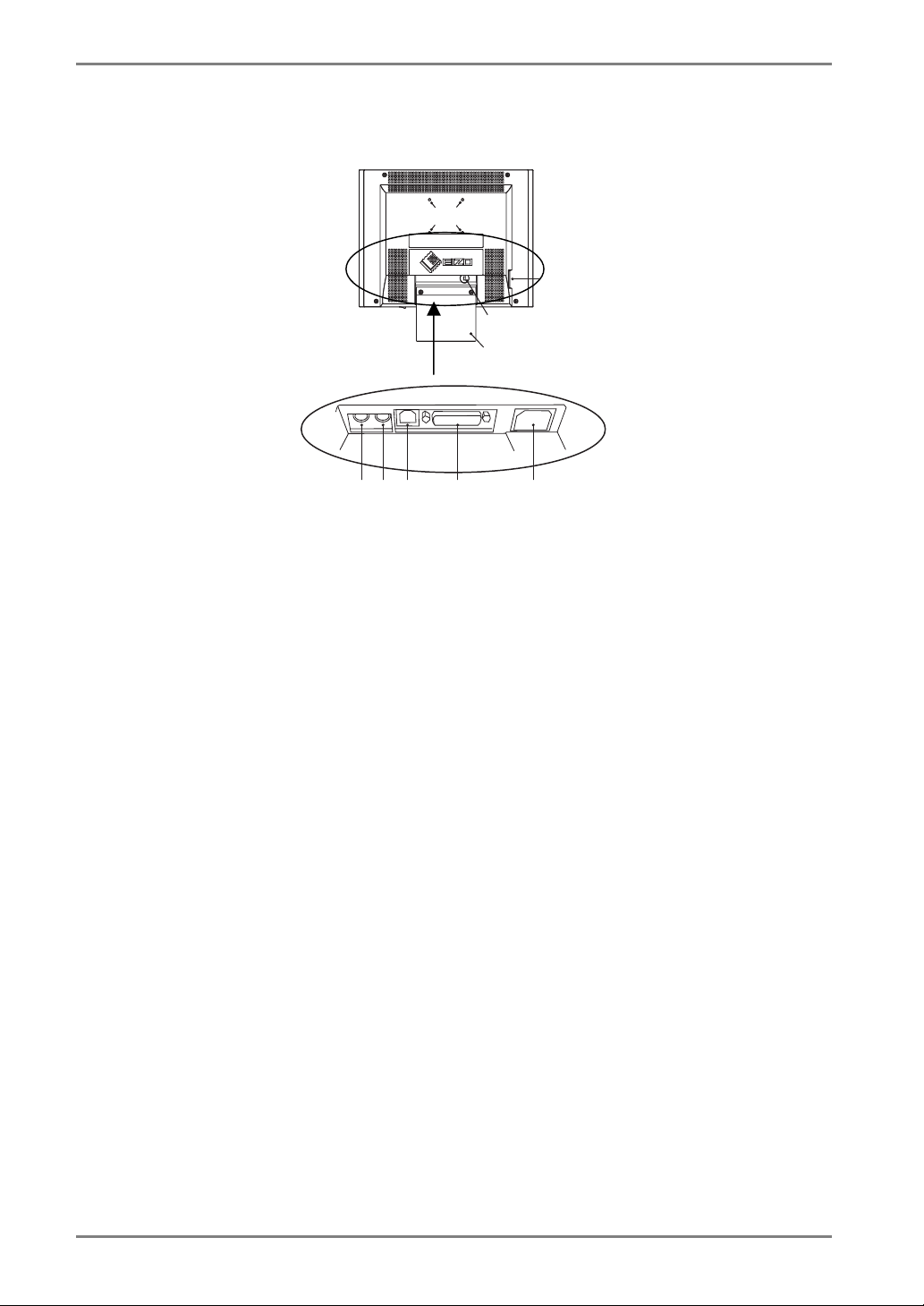
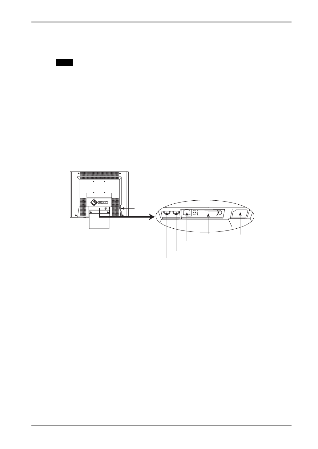
Rear
(10)
(8)
(9)
(11)
(3)(4) (5) (6) (7)
(3) Mouse Connector
(4) Keyboard Connector
(5) Ethernet Connector (10 Base-T)
(6) Parallel Connector
(7) Power Connector
(8) Serial Connector (RS-232C) (531L/531LT-GR)
1
(9) Security Lock*
(10) Holes for Mounting an Arm Stand*
2
(11) Stand
1
This allows for connection of a security cable. This lock supports Kensington's
*
MicroSaver security system. For further information, please consult:
Kensington Technology Group
2855 Campus Drive, San Mateo, CA
94403 USA
1-800-650-4242, x3348
Intl: 650-572-2700
Fax: 650-572-9675
http://www.kensington.com
2
Please see “11. REFERENCE” on page 100 for details.
*
8 1. INTRODUCTION
Page 9

1-5. Overview
Directions for the eClient’s Setup
2. CONNECTING THE p.10
3. SETTING UP THE eClient
3-1. WBT Setup Wizard p.13
3-2. Dial-Up Connection p.27
4. ADDING & CHANGING A CONNETION NAME
Directions for the eClient’s Operation.
5. LOGON & LOGOFF
4-1. Adding a Connection Name p.34
4-2. Deleting a Connection p.52
4-3. Editing a Connection p.53
4-4. Setting an Autostart Connection p.55
5-1. Logon to a WTS p.56
5-2. Logoff from the WTS p.59
English
Directions for Changing Terminal Properties’ Settings.
6. USING THE TERMINAL PROPERTIES
6-1. General Information & Reset to Default p.61
6-2. Input Devices Settings p.63
6-3. Colors & Power Save Settings p.68
6-4. Network Settings p.70
6-5. Printer Settings p.73
6-6. Dial-Up (PPP) Connection Settings p.76
6-7. ICA Settings p.77
6-8. Product Information, Security, & Updating Software p.80
Directions for Using a DHCP Server, a Practical Setup
7. PRACTICAL SETUP p.87
1. INTRODUCTION
9
Page 10

English
2. CONNECTING THE eClient
This chapter shows how to connect the eClient to a WTS.
2-1. Setting up the eClient
Please observe the following cautions when connecting the eClient.
WARNING
Place the eClient on a strong, stable surface.
A unit placed on an inadequate surface may fall, resulting in injury
or equipment damage. If the unit falls, disconnect the power
immediately and have the unit checked by a qualified service
engineer before using it again. Using a unit after it has been
dropped may result in fire or electric shock.
Set the unit in an appropriate location.
* Do not install in a dusty or humid environment.
* Do not place in a location where steam can have direct contact
with the screen.
* Do not place near heat generating devices or a humidifier.
10 2. CONNECTING THE eClient
Page 11
2-2. Connecting the eClient
NOTE
• Before connecting the eClient, confirm the following:
• The eClient is turned off.
• The WTS is turned on.
• Connect the peripherals to the appropriate connectors of the unit.
1. In case of connecting the WTS through LAN:
Connect the eClient to the network with an ethernet cable.
In case of a dial-up or dial-in connection (531L/531LT-GR only):
Connect the eClient to a modem or a modem card.
English
Modem
Card
Printer
Network
Keyboard
Mouse
Power Cord
2. Plug a keyboard and a mouse into the eClient. If using other devices,
please connect them to the appropriate connectors.
If using a touch panel, a mouse should not be connected (531LT-GR only).
2. CONNECTING THE eClient
11
Page 12

English
3. Plug the power cord into the power connector.
WARNING
Use the enclosed power cord and connect to the standard
power outlet of your country.
Be sure to remain within the rated voltage of the power cord.
Not doing so may cause in fire or electric shock.
The equipment must be connected to a grounded main
outlet.
Not doing so may cause in fire or electric shock.
12 2. CONNECTING THE eClient
Page 13
3. SETTING UP THE eClient
This chapter presents how to prepare for a connection with a WTS when the eClient
starts up for the first time.
3-1. WBT Setup Wizard
1. Turn on the power switch.
The power indicator turns green.
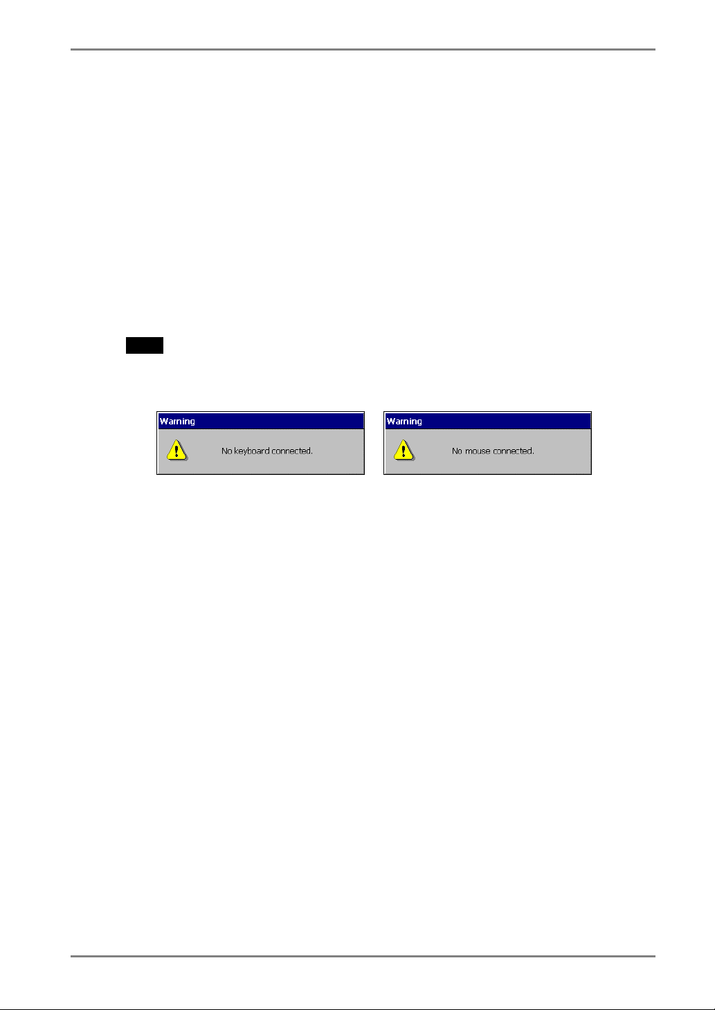
NOTE
• When no picture is displayed, or when the following message is shown on the
screen, please refer to “8. Troubleshooting” on page 92.
- Message -
English
In use of a stylus or a finger as an input device, “No Mouse Connected!!” caution
does not effect your operation (531LT-GR only).
3. SETTING UP THE eClient
13
Page 14

English
2. “Touch panel calibration” is displayed (531LT-GR only).
Five targets are displayed on the screen. Press the targets with a stylus or a
fingertip to locate the center of the touch panel. If you accidentally touched the
screen in the wrong spot during calibration, you will distort the touch panel
calibration.
3. “Calibration measured” window is displayed when you finished
(531LT-GR only).
Click the “Enter” key to accept the settings.
14 3. SETTING UP THE eClient
Page 15
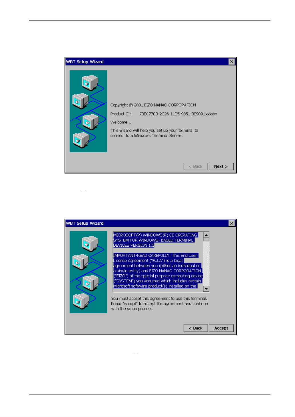
4. “WBT Setup Wizard” is displayed.
Click [N
ext>].
English
5. End User License Agreement page is displayed.
Read the content and click [A
ccept] to continue.
3. SETTING UP THE eClient
15
Page 16
English
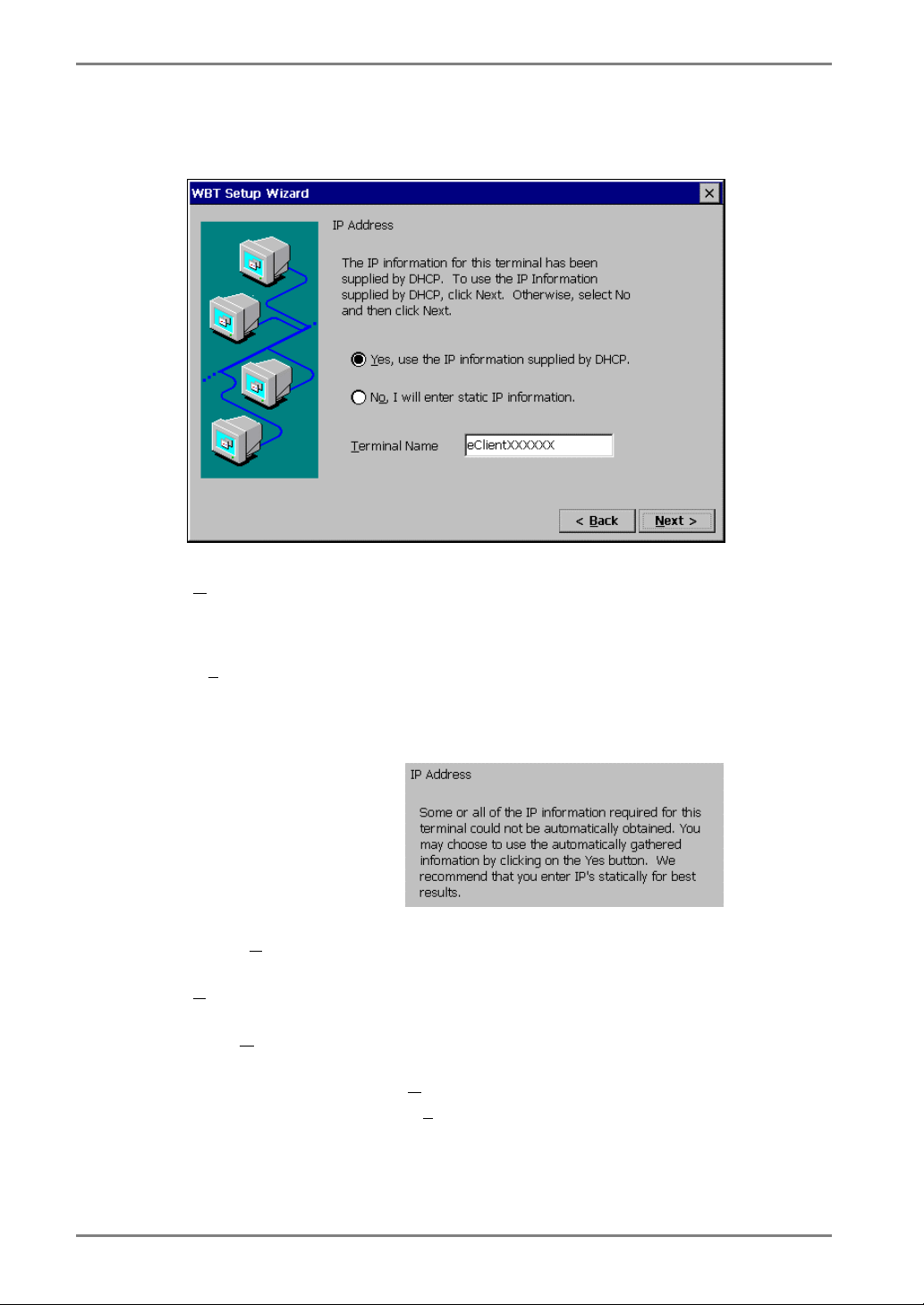
6. IP address setting page is displayed.
es, use the IP information supplied by DHCP.]
[Y
...................................Select this when using DHCP service. All the
, I will enter static IP information.]
[No
...................................Select this when not using DHCP service. Enter the IP
necessary information of the eClient including the IP
address will be obtained by the DHCP.
address of the eClient.
If DHCP service is not in operation, following message
appears.
Type a [ T
Desktop Client) protocol.
erminal Name] ................Type the name to identify this unit on the network.
[T
Click [N
Refer to step 8 if you select [Y
Refer to step 7 if you select [No
erminal Name] for connection to a WTS by the RDP (Microsoft Remote
ext>].
16 3. SETTING UP THE eClient
es, use the IP information supplied by DHCP.]
, I will enter static IP information.]
Page 17
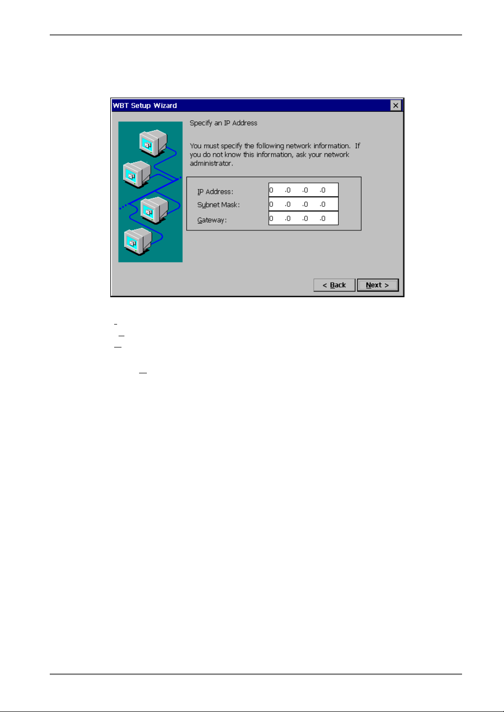
7. IP address page is displayed.
P Address] ........................Type the IP address of the unit.
[I
bnet Mask] ....................Type the subnet mask of the network.
[Su
ateway] ...........................Type IP address of the Gateway machine if necessary.
[G
Click [N
ext>] when finished.
English
3. SETTING UP THE eClient
17
Page 18
English
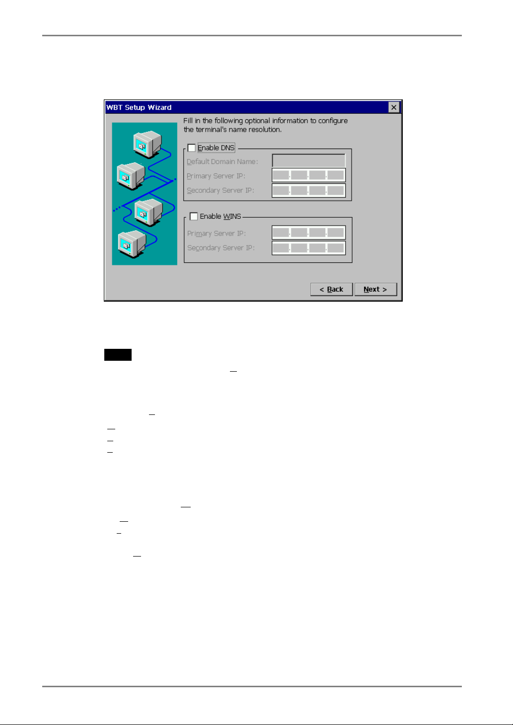
8. DNS and WINS settings page is displayed.
This check box should be marked when DNS or WINS is used.
NOTE
• Skip the page by clicking [N
If using DNS
Click the [Enable DNS] check box to activate this box.
[D
[P
[S
If using WINS
Click the [Enable WINS] check box to activate this box.
[Prim
[Sec
Click [N
ext>] if DNS or WINS is not used.
efault Domain Name] .....Type the default domain name.
rimary Server IP]..............Type the DNS primary Server IP address.
econdary Server IP] ..........Type the DNS secondary Server IP address.
ary Server IP]..............Type the WINS primary Server IP address.
ondary Server IP] ..........Type the WINS secondary Server IP address.
ext>] when finished.
18 3. SETTING UP THE eClient
Page 19
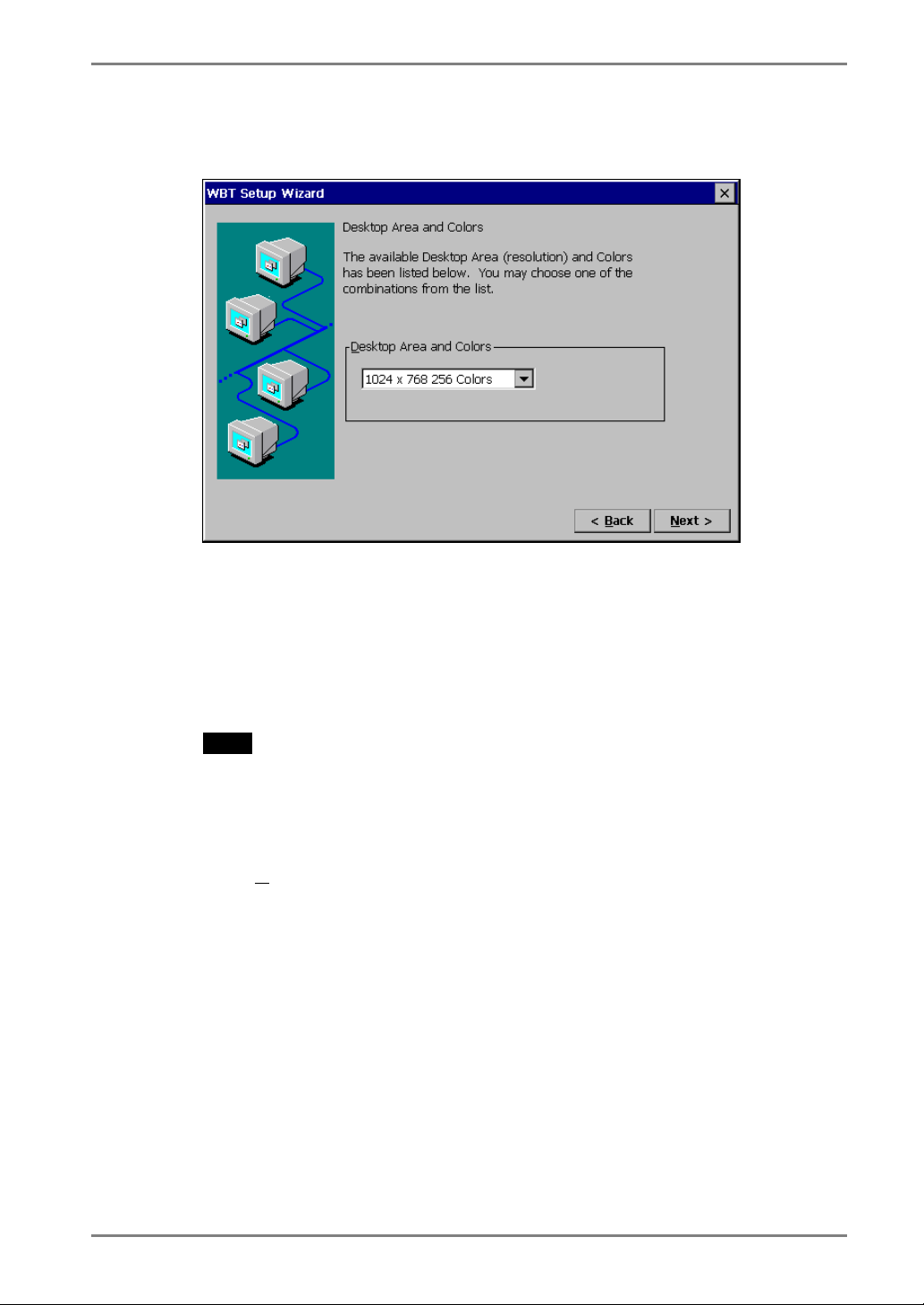
9. Desktop area resolution and color settings page is displayed.
Select the preferable display mode from the two available modes:
· 1024 x 768 (256 colors)
· 1024 x 768 (65,536 colors)
· 768 x 1024 (256 colors) (531L/531LT-GR only)
· 768 x1024 (65,536 colors) (531L/531LT-GR only)
English
NOTE
• The orientation of 768 x 1024 is a portrait. (768 x 1024 available for Citrix ICA.
When RDP is used, 640 x 480 is displayed on center of the screen.)
To use the portrait orientation mode, please change the monitor’s tilt stand to
an arm, and set the monitor portrait (90° clockwise).
Click [N
3. SETTING UP THE eClient
ext>] when finished.
19
Page 20
English
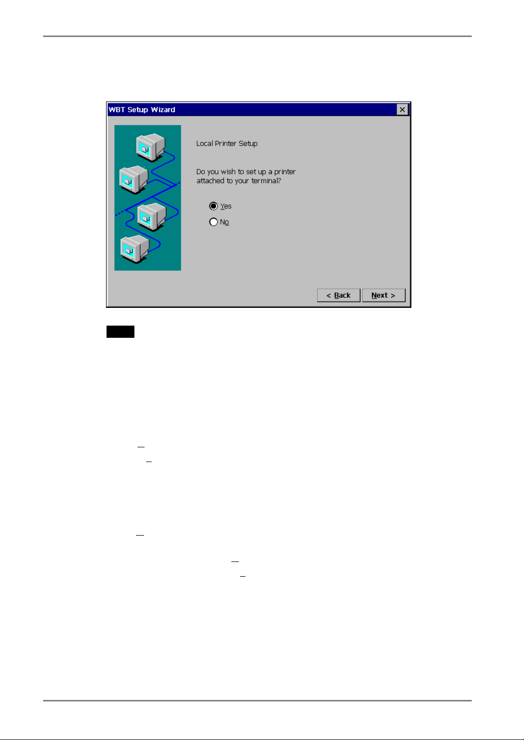
10. Local Printer Setup page is displayed.
NOTE
• The following is required to install a local printer;
* A printer is connected to the printer port or the serial connector of the eClient.
* An RDP protocol is used for connection to a WTS.
* Microsoft Windows 2000 Server / Advanced Server / Datacenter Server is
installed in a WTS
• A Local Printer mentioned here is a printer connected directly to the Parallel
Connector of the unit.
Select [Y
Select [No
* When not using a Local Printer
* When using a ICA protocol for connection to a Server
Click [N
Refer to step 11 if selecting [Y
Refer to step 17 if selecting [No
es] when using a local printer.
] in the following cases:
* When the OS of the Server is Windows NT Server 4.0 Terminal Server
Edition
ext>] when finished.
es].
].
20 3. SETTING UP THE eClient
Page 21

11. Printer port selection page is displayed.
Select a printer port.
The eClient supports LPT1.
Click [N
ext>].
English
3. SETTING UP THE eClient
21
Page 22
English
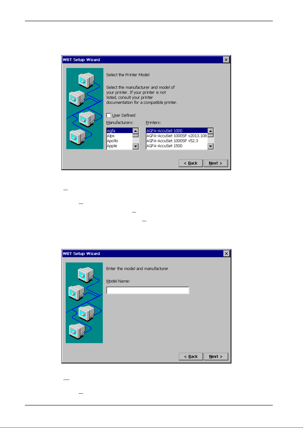
12. Printer model selection page is displayed.
Select a manufacturer and model of your printer.
ser Defined].....................Click the check box if your printer is not listed.
[U
Click [N
Refer to step 13 if clicking [U
Refer to step 14 if not clicking [U
ext>] when finished.
ser Defined].
ser Defined].
13. Printer model and manufacturer settings page is displayed.
odel Name] ....................Type a model and manufacturer of your printer.
[M
Click [N
ext>] when finished.
22 3. SETTING UP THE eClient
Page 23

14. Printer name setting page is displayed.
Name the printer or use the indicated name. (Some programs do not support the
Server and the printer name combinations of more than 31 characters.)
Click [N
ext>] when finished.
English
3. SETTING UP THE eClient
23
Page 24
English
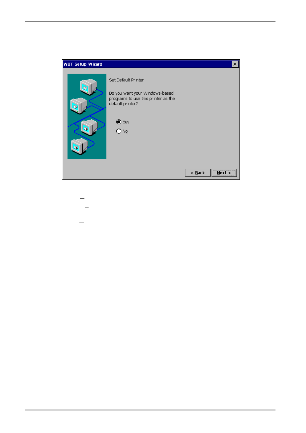
15. Default printer setting page is displayed.
Select [Y
Select [No
Click [N
es] to set this printer as the default printer.
] not to set this printer as the default printer.
ext>].
24 3. SETTING UP THE eClient
Page 25
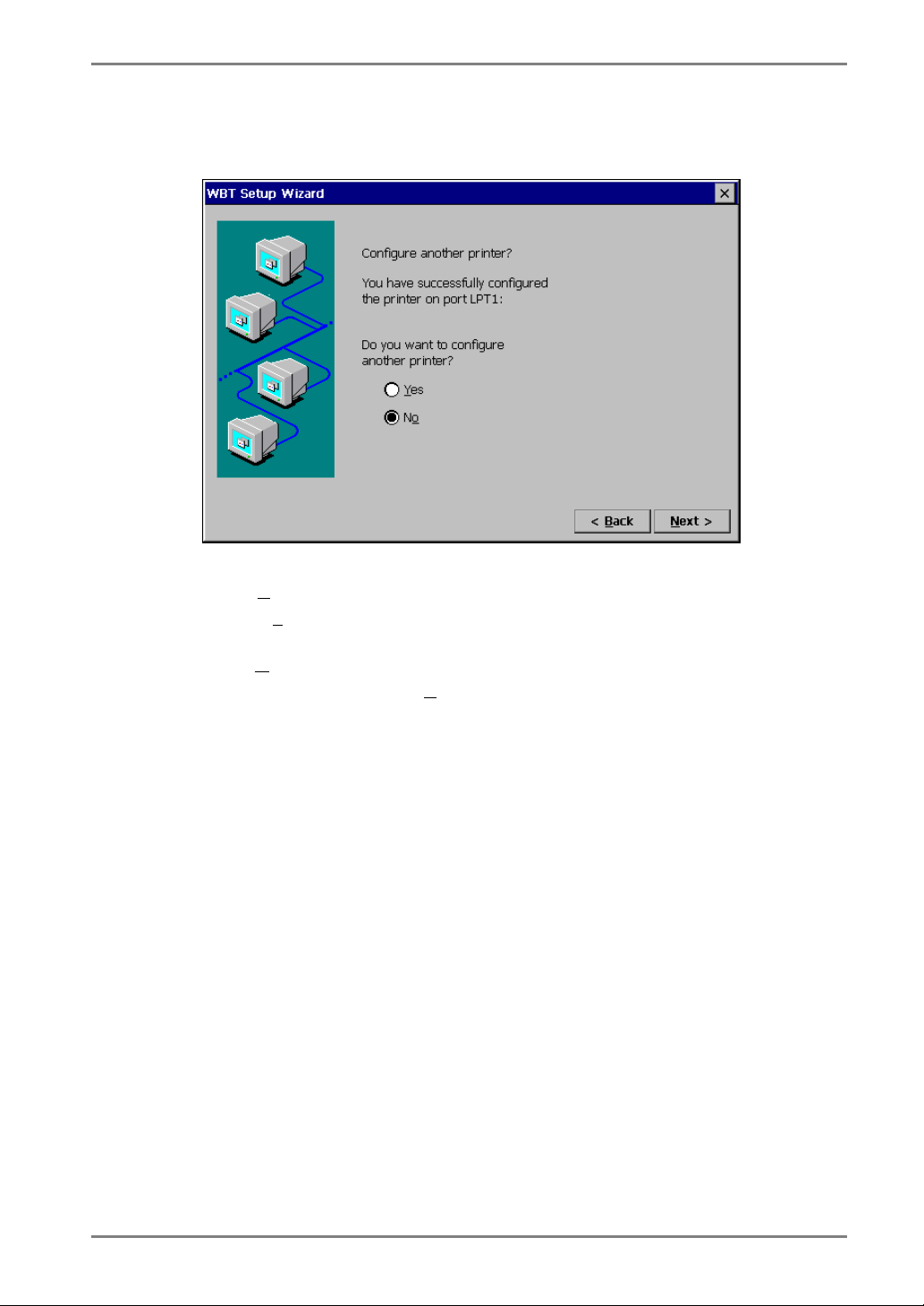
16. Another printer configuration page is displayed.
Select [Y
Select [No
Click [N
Refer to step 11 if selecting [Y
Refer to step 17 if selecting [No].
es] to configure another printer.
] to finish printer settings.
ext>] when finished.
es].
English
3. SETTING UP THE eClient
25
Page 26
English
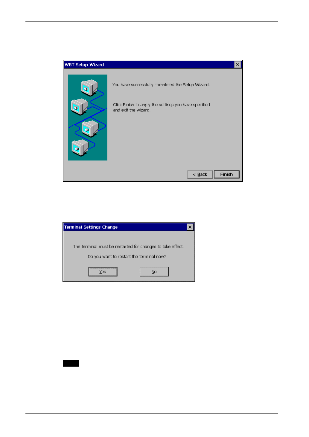
17. The last page of the “WBT Setup Wizard” is displayed.
Click [Finish] in the last page to display a “Terminal Settings change” dialog box.
(This dialog box is displayed only when there are changes in the settings.)
Click [Yes] to restart the eClient to activate the changes.
· Click [No] to finish the “WBT Setup Wizard” and display “Terminal Connection
Manager” on the screen. The setting is not activated until the eClient is
restarted.
This completes the eClient settings.
The “Terminal Connection Manager” dialog box will be displayed after restarting.
NOTE
• When you are connecting to the WTS with a LAN card, another installation for
a LAN card connection must be completed. Please follow the next page.
• When you are connecting to the WTS with a modem, another installation for a
modem connection (a dial-up connection) must be completed. Please follow
the “3-2. Dial-up Connection”, page 27.
26 3. SETTING UP THE eClient
Page 27
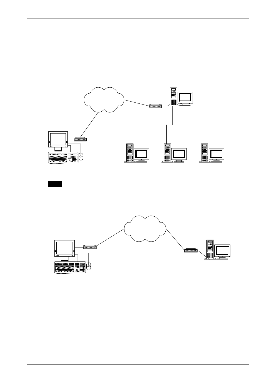
3-2. Dial-Up Connection (531L/531LT-GR only)
The following details the installation of a dial-up connection for RAS (Remote Access
Service).
No restriction of the protocol is made for the “Dial-up connection”. To use a dial-up
connection requires an RAS server in operation.
[Dial-up Connection]
Telephone
Lines
RAS Server
English
eClient
NOTE
• Another type of connection using a modem, a dial-in connection, is available to
connect to the WTS with an ICA protocol. Please see page 40.
[Dial-in Connection]
eClient
WTS
WTS
Telephone
Lines
FTP Server
WTS
1. Press “F2” key in the “Terminal Connection Manager”.
3. SETTING UP THE eClient
27
Page 28
English
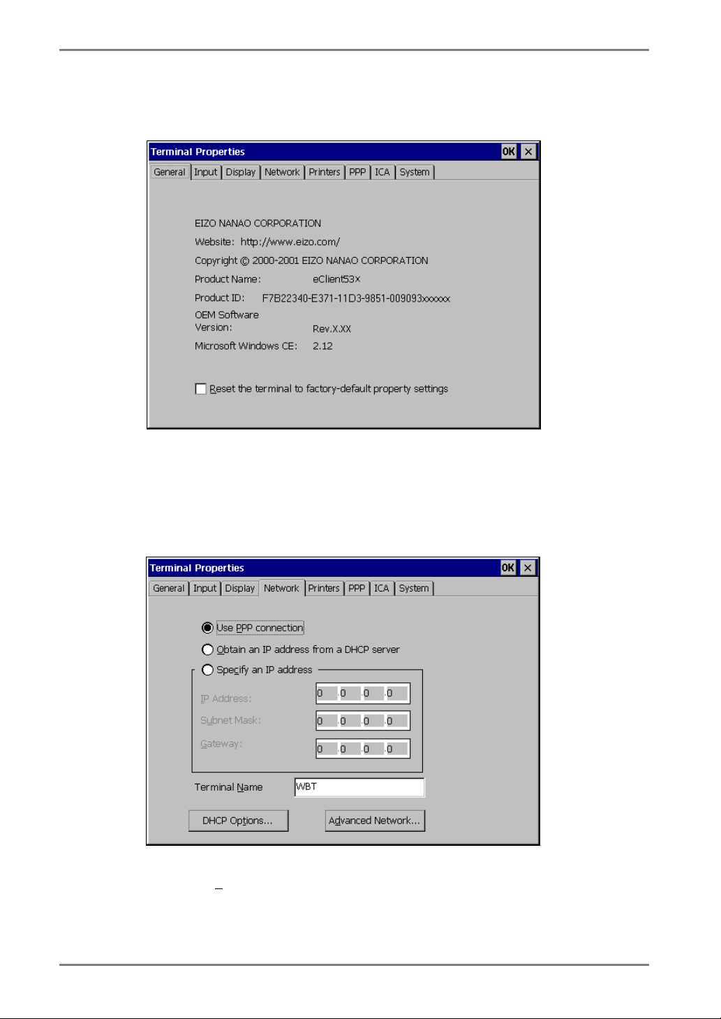
2. “Terminal Properties” is displayed.
Click the [Network] tab.
3. The network setting window is displayed.
Select [Use P
Click [PPP] tab when finished.
PP connection or another network adapter].
28 3. SETTING UP THE eClient
Page 29
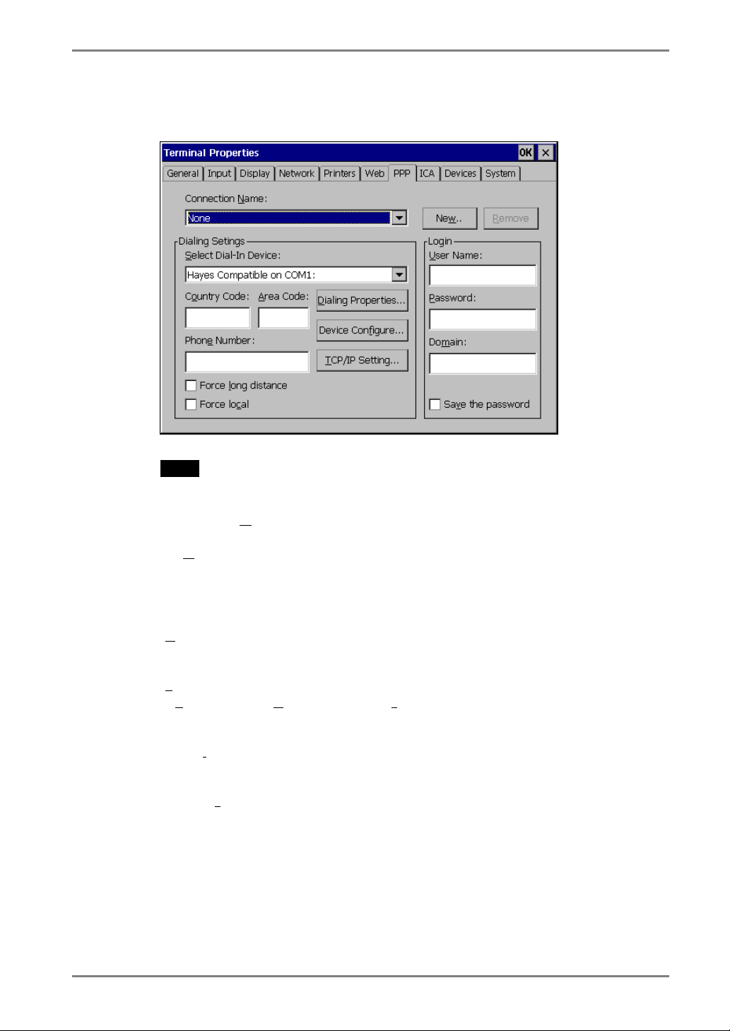
4. The dial-up setting window is displayed.
English
NOTE
• Enter your information in the pertinent fields.
[Connection N
([None] indicates no connection name chosen.)
...]...............................Click the button to create a new dial-up connection
[New
emove] ............................Delete the connection name displayed currently.
[R
[Dialing Settings]
elect Dial-In Device].........Choose a modem connecting device type.
[S
untry Code:], [Area Code:], [Phone Number]
[Co
...................................Enter a country code, an area code, and a phone
[Force l
[Force loc
ong distance]...........Click here to use the country code, area code, and the
ame] ............Choose a connection name for a dial-up connection.
name.
“Create New Dial-Up Connection” dialog box is
displayed.
Enter the name and click [OK].
number for the connection name.
phone number when connecting to the connection
name.
al]........................Click here to use only the phone number when
connecting to the connection name. (In case the area
code of the connection name is different from the
present area code.)
3. SETTING UP THE eClient
29
Page 30
English
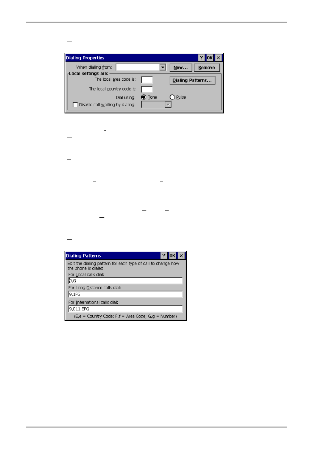
ialing Properties...]
[D
...................................Click the button to set information of the sender.
[When dialing f
ew...]...............................Click this to add a new sender’s location.
[N
emove] ............................Remove the current sender’s location.
[R
[Local Settings are...]
[The local a
...................................Enter the area code and the country code of the
[Dial using:] ........................Choose your using dial from;
[Disable call w
...................................Click the check box and enter the number to disable
ialing Patterns...].............Click the button and use this group box to set your
[D
rom:] ..........Choose the sender’s location.
“Create New Location” dialog box is displayed.
Enter a new sender’s location and click [OK].
rea code is:], [The local country code is:]
sender’s location.
one] / [Pulse]
[T
aiting by dialing:]
call waiting by dialing.
modem’s dialing patterns.
Click [OK] when finished.
Click [OK] of the [Dialing Properties] when finished.
“Terminal Properties” is displayed.
30 3. SETTING UP THE eClient
Page 31

English
[Device Conf
...................................Click the button the detailed settings of the modem.
[Port Settings] tab
[M
anual Dial (user supplies dial strings)]
...................................Click this box to set up for manual dialing.
[Terminals]
[Use terminal window bef
...................................Click this box to record terminal window information
[Connection Preferences]
aud Rate].........................Set data transmission rate from 110 to 115,200 bps.
[B
ata Bits]...........................Set data bits.
[D
arity]................................Set enabling to check the data's transmission.
[P
top Bits] ...........................Set length of the Stop Bits.
[S
low Control]....................Set Flow Control.
[F
[Call Option] tab
ancel the call if not connected within]
[C
...................................Click the box and set the intervals to the right box
ait for dial tone before dialing]
[W
...................................Click to dial after dial tone.
[Wait for credit card t
...................................Click the box and set the intervals before canceling the
tra Settings (Special modem commands may be inserted into the dial strings)]
[Ex
...................................Enter a special modem command if required.
Click [OK] on [Device Properties] when finished. “Terminal Properties” will be
displayed.
igure...]
(Please refer to the instruction manual of a modem for
settings of the modem.)
ore / after Dialing]
before or after dialing.
before canceling the connection in case of connection
failure.
one]
connection in use of a credit card for dialing.
NOTE
• When changing settings in the [Device Properties], click the [Call Option] tab
before clicking [OK] to close the window.
3. SETTING UP THE eClient
31
Page 32

English
CP/IP Settings...]
[T
Click the button to set the TCP/IP settings of the WTS.
se server-assigned IP address]
[U
...................................Click the box to use a server-assigned IP address.
pecify an IP address] ........Enter a provided IP address.
[S
[Use serv
...................................Click the box to use a server-assigned DNS or WINS
[Specif
...................................Enter an DNS or WINS server IP address provided.
er-assigned DNS or WINS server IP address]
server IP address.
y DNS or WINS server IP address]
32 3. SETTING UP THE eClient
Page 33

English
[Primary DNS], [Secondary DNS]
...................................Enter IP address of the primary DNS and IP address of
the secondary DNS.
[Primary WINS], [Secondary WINS]
...................................Enter IP address of the primary WINS and IP address
of the secondary WINS.
[Use software c
...................................Click to use software compression.
[Use IP he
...................................Click to IP header compression.
[Use default g
Click [OK] in the [TCP/IP Settings] when finished.
“Terminal Properties” is displayed.
ser’s Name], [Password], [Domain]
[U
...................................Enter your information in the pertinent fields. If you
e the password] ............Click to save the password.
[Sav
Click [OK] in the “Terminal Properties” when finished.
The “Terminal Properties” saves the settings and close.
This completes the dial-up connection settings.
A small window will be displayed on the right bottom of the window if the settings
are successfully installed.
ompression]
ader compression]
ateway]..........Click to use the default Gateway.
do not know the information, contact your system
administrator.
3. SETTING UP THE eClient
33
Page 34

English
4. ADDING & CHANGING A CONNETION NAME
This chapter shows how to add, delete, and modify connection names to a WTS.
All the settings are managed in the “Terminal Connection Manager”.
4-1. Adding a Connection Name
These are settings for the Server connection.
Each protocol has different settings. Please install the appropriate settings.
• In use of the Microsoft Remote Desktop Client (RDP) page 35
• In use of the Citrix ICA Client (ICA) page 40
NOTE
• Please install Citrix MetaFrame server into the Server when using the ICA protocol.
34 4. ADDING & CHANGING A CONNETION NAME
Page 35

In Use of RDP Protocol
1. Display [Terminal Connection Manager].
English
Click the [Configure] tab and [A
WTS.
dd...] to set the connection information of the
2. Protocol selection dialog box is displayed.
Select the “Microsoft Remote Desktop Client” (RDP)
Click [OK] when finished.
4. ADDING & CHANGING A CONNETION NAME
35
Page 36

English
3. “WTS Connection Wizard” is displayed.
[Na
me]................................Type the connection name to the Server. Name the
erver] ...............................Type the IP address or the name of the Server, or
[S
ow Speed Connection].....Click the check box when making a low speed
[L
Click [N
ext>] when finished.
connection to differentiate the Server from others.
WINS setting is necessary when the name is typed.
connection. Enable this function when connecting
through a Remote Access Service using a modem that
takes time to receive data from the Server.
36 4. ADDING & CHANGING A CONNETION NAME
Page 37

4. Automatic Logon setting page is displayed.
Type the name, the password, and the domain name of the WTS beforehand to
enable an Automatic Logon to the WTS after connecting.
English
NOTE
• If an Automatic Logon is not needed, click [N
Click the check box of the [A
sername]..........................Type the name to connect the WTS.
[U
assword] ..........................Type the password for the user name.
[P
omain] ............................Type the domain name.
[D
Click [N
ext>] when finished.
utomatic Logon] to enable the item.
ext>].
4. ADDING & CHANGING A CONNETION NAME
37
Page 38

English
5. Specifying an application to run after connecting to a WTS is
displayed.
Select whether to display the Windows desktop screen or start up an application.
[D
esktop] ............................Select this to start the Windows desktop screen when
pplication file name:] .....Select this to start an application when you connect.
[A
[W
orking directory:] ...........Input the name of the application and the working
you connect.
directory if necessary.
NOTE
• When the [A
the specified application will be started after logging on. In this case, closing
the application logs off and disconnects from the WTS.
Click [N
pplication file name:] and the [Working Directory] are named, only
ext>] when finished.
38 4. ADDING & CHANGING A CONNETION NAME
Page 39

English
6. The last page of the “WTS Connection Wizard” is displayed on the
screen.
Click [Finish] to return to the “Terminal Connection Manager” dialog box.
The registered connection name is displayed in the “Terminal Connection
Manager” dialog box.
This completes the setup of the eClient for connection to a WTS with the RDP
protocol.
NOTE
• Please repeat step 1 to 6 to entry more than two kinds of connections.
4. ADDING & CHANGING A CONNETION NAME
39
Page 40

English
In Use of the ICA protocol
1. Click the [Configure] tab.
Click [A
dd...].
2. “New Connection” dialog box is displayed on the screen.
Select “Citrix ICA Client” (ICA).
Click [OK] when finished.
40 4. ADDING & CHANGING A CONNETION NAME
Page 41

3. “Specify Connection Type” dialog box is displayed.
[Network Connection]........Select for network connection.
[Dial-In Connection]...........Select for dial-in connection.
Click [N
Go to step 4 when selecting [Network Connection].
Go to step 5 when selecting [Dial-In Connection].
ext>] when finished.
English
4. ADDING & CHANGING A CONNETION NAME
41
Page 42

English
4. Citrix Server or published application selection page is displayed.
1) Select [S
2) Click [Server L
erver] (WTS) or [Published Application].
ocation…].
[Server Group]................Select the WTS Group to connect. (A WTS Group
consists of [Primary], [Backup 1], and [Backup 2].
The WTS will be searched in order of [Primary],
[Backup 1], and [Backup 2].
dd]...............................Add another Server address. Type the Server Name
[A
or IP address. (The typed Server Name or IP
address will be shown in the [Address] list.
elete]...........................Delete the selected WTS from the [Address] list.
[D
[Default L
[Address] ........................The added WTS IP address appears.
Click the drop-down list box below [Address]. Select the appropriate WTS
protocol from the list.
[TCP browser] ................Citrix MetaFrame uses UDP protocol to search for the
[TCP + HTTP browser]...Select this when not using a UDP because of the
[SSL + HTTPS browser]
...................................This is not available with eClient.
Click [OK] to return to the previous page and save the adjustments.
ist] ...................Revert the state of the [Address] list to the saved one.
WTS. Select this when using a UDP protocol.
firewall in your network environment.
42 4. ADDING & CHANGING A CONNETION NAME
Page 43

English
3) Click [R
4) Select a WTS or a published application from the list.
NOTE
• Published applications are specific application set by a system administrator.
When connected, you are presented with the application itself.
Click [Next>].
efresh] to refresh the list to the newest information.
4. ADDING & CHANGING A CONNETION NAME
43
Page 44

English
5. “Dial-In Devices” dialog box is displayed.
NOTE
• This setting is available in the 531L/531LT-GR only.
• A dial-in connection is not available during a dial-up connection. Disconnect
the dial-up connection before making dial-in connection.
[Dial-In Device:]..................Select the device name connected to the modem.
[Phone Number] .................Enter a country code, an area code, and a phone
[Use Tone Dialing]..............Click to use tone dialing.
[Configure] .........................Click the button the detailed settings of the modem.
[Hayes Compatible on COM1] is available for the
eClient.
number for the connection.
(Please refer to the instruction manual of the modem
for details.)
[Port Settings] tab
anual Dial (user supplies dial strings)]
[M
...................................Click this box to set up for manual dialing.
[Terminals]
[Use terminal window b
...................................Click this box to record terminal window information
[Use terminal window a
...................................Click this box to record terminal window information
efore dialing]
before dialing.
fter dialing]
after dialing.
44 4. ADDING & CHANGING A CONNETION NAME
Page 45

English
[Connection Preference]
aud Rate].........................Set the data transmission rate from 110 to 115,200.
[B
ata Bits]...........................Set the data bits.
[D
arity]................................Set to check the data’s appropriate transmission.
[P
top Bits] ...........................Set the length of the Stop Bits.
[S
low Control]....................Set Flow Control.
[F
[Call Option] tab
ancel the call if not connected within]
[C
...................................Click the box and type the interval to the right box
before canceling the connection in case of connection
failure.
ait for dial tone before dialing]
[W
...................................Click to dial after dial tone.
[Wait for credit card t
...................................Click to set the intervals before canceling the
xtra Settings (Special modem commands may be inserted into the dial strings)]
[E
...................................Enter a special modem command if needed.
Click [OK] on [Device Properties] when finished. The dialog box saves the settings
and closes.
• Click the [Close] button to cancel the settings.
one]
connection using a credit card.
NOTE
• When changing settings in the [Device Properties], click the [Call Option] tab
before clicking [OK] to close the window.
Click [N
ext>].
4. ADDING & CHANGING A CONNETION NAME
45
Page 46

English
6. A title for the ICA connection page is displayed.
Type a connection name of the WTS.
Click [N
ext].
7. An application selection page is displayed.
Specify the command line and the working directory of an application to operate.
NOTE
• Leave these fields blank and click [N
[Command Line:]................Type the application name and the path.
[Working Directory:] ..........Type the working directory for the application.
NOTE
• When the [Command Line] and the [Working Directory] are named, only the
specified application will be started after logging on. In this case, closing the
application logs off from the WTS.
Click [N
ext>] when finished.
ext>] to run a Windows desktop.
46 4. ADDING & CHANGING A CONNETION NAME
Page 47

8. Automatic logon settings page is displayed.
Type the name, the password, and the domain name of the WTS beforehand to
enable an Automatic logon to the WTS after connecting.
NOTE
• If an Automatic Logon is not needed, click [Next.]
[User Name:].......................Type the name to automatically connect the WTS.
[Password:] .........................Type the password for the user name.
[Domain:] ...........................Type the domain name.
[Allow Smart Card logon]...This is not available with eClient.
Click [N
ext>] when finished.
English
4. ADDING & CHANGING A CONNETION NAME
47
Page 48

English
9. Colors selection page is displayed.
Set the colors of the WTS’ screen.
NOTE
• Thousands can be selected only when the color setting of the eClient is 65536
colors.
Click [N
ext>] when finished.
48 4. ADDING & CHANGING A CONNETION NAME
Page 49

English
10. Compression and encryption, and sound settings page is displayed.
[Use Printer Configuration Utility]
...................................Click the check box to install the printer at the [ICA
Client Printer Configurations].
[Compress Data Stream].....Click the check box to reduce the amount of data
transferred between the WTS and the eClient, which
can increase performance. (If you have sufficient
bandwidth, leave compression off to conserve
processing power on the WTS.)
[SpeedScreen:].....................Select the speed at which the keyboard and mouse
perform on the screen.
Select [On] when connecting to the WTS with a
dial-up connection. Select [Off] when connecting to
the WTS with a LAN connection. Select [Auto] to
automatically switch the speed depending on the
network environment.
[Encryption Level:] .............Encryption level can be selected from RC5 (128 bit -
Login Only), basic, RC 5 (40 bit), RC5 (56 bit), RC5
(128 bit). The level becomes higher as the bit gains.
RC5 (128 bit - Login Only) indicates the 128 bit level
security available only at logon.
Click [N
ext>] when finished.
4. ADDING & CHANGING A CONNETION NAME
49
Page 50

English
11. Firewall settings page is displayed.
NOTE
• These settings are effective when connecting to the WTS through internet.
• If no change is made, the settings under the [Firewall settings] of [Global ICA
Client Settings] will be applied (see page 78 for details).
Set the connection to the WTS through the SOCKS proxy server when the SOCKS
proxy server is working to limit the access to the WTS.
[Proxy]
Click the drop-down list box, and select [SOCKS] from the list.
(The [Secure (HTTPS)] setting is not available with eClient.)
[Address of SOCKS proxy to use] / [Port]
...................................Type the IP address of the SOCKS proxy server and
[Use alternate address through firewalls]
...................................Click the check box to connect to the WTS through
[SSL/TLS Relay]
[Address of SSL relay to use] / [Port]
...................................These are not available with eClient.
Click [Finish] when finished.
[Terminal Connection Manager] is displayed.
The registered connection name is displayed in the “Terminal Connection
Manager” dialog box.
the port number of the proxy server.
the Firewall.
50 4. ADDING & CHANGING A CONNETION NAME
Page 51

English
This completes the setup of the eClient for connection to a Server with the ICA
protocol.
NOTE
• Please repeat the step 1 to 11 when you adding another connection name.
4. ADDING & CHANGING A CONNETION NAME
51
Page 52

English
4-2. Deleting a Connection
This function deletes an existing Connection Name.
1. Display the “Terminal Connection Manager” dialog box.
2. Click the [Configure] Tab.
3. Select the Connection Name you want to delete.
4. Click [Delete].
5. “Confirm Connection Delete” dialog box is displayed.
Click [Y
es] to delete the information of the selected WTS.
52 4. ADDING & CHANGING A CONNETION NAME
Page 53

4-3. Editing a Connection
This function modifies attributes of the WTS connections.
1. Display the “Terminal Connection Manager” dialog box.
2. Click the [Configure] Tab.
3. Select the connection you want to modify.
4. Click [Edit...].
5. [Edit Connection] dialog box or [Edit Connection Details] is
displayed.
• For RDP Connection
English
(Please see pages 35 to 39 for each setting.)
[Net Connections] tab........Change connection settings to a WTS.
[Application] tab................Change a description of an application on a startup.
Click [OK] to enable the settings.
4. ADDING & CHANGING A CONNETION NAME
53
Page 54

English
• For ICA Connection
(Please see to pages 40 to 50 for each setting.)
[Server/Dial-In] tab .............Either Server or Dial-In tab is displayed depending on
the connection type.
[Server] Tab (for LAN connection)
To change the WTS / the public application to use
[Dial-In] Tab (for Dial-In connection)
To change settings of the Dial-In connection
(531L/531LT-GR only)
[Application] tab.................To change a description of an application to run
[Logon] tab .........................To set/cancel Automatic Logon
[Windows] tab ....................To set the colors of the WTS screen
[Options] tab ......................To set/cancel the printer after connecting the WTS,
compression of data, the speed at which the keyboard
and mouse perform on the screen, and encryption level
setting.
[Title] tab............................To change the connection name
[Firewall Settings] tab .........To change the settings on the Firewall and the proxy
WTS
If no change is made in this settings, the settings under
the [Firewall settings] of “Global ICA Client Settings”
will be applied (see page 78 for details).
Click [OK] to enable the settings.
NOTE
• When changing settings in the Dial-In connection, click and show the [Call
Option] tab of [Device Properties] of the [Dial-In] tab before clicking [OK] to
close the window.
54 4. ADDING & CHANGING A CONNETION NAME
Page 55

4-4. Setting an Autostart Connection
This function configures a connection to start automatically each time the eClient is
turned on. (This function is available for a LAN connection.)
1. Display the “Terminal Connection Manager” dialog box.
2. Click the [Configure] tab.
3. Select the desired Connection Name for Autostart Connection.
4. Click [Startup...]
5. “Connection Startup” dialog box is displayed.
English
Select [A
Click [OK] to save the setting. The setting is effective from the next startup.
4. ADDING & CHANGING A CONNETION NAME
utomatically start the selected connection at startup.]
55
Page 56

English
5. LOGON & LOGOFF
This chapter shows how to log on to and log off from a WTS.
5-1. Logon to a WTS
1. Turn on the eClient.
2. “Terminal Connection Manager” dialog box is displayed.
Please follow the instruction depending on the network environment of the eClient.
LAN connection
Go to step 3.
Modem connection (531L/531LT-GR only)
* Dial-Up connection to the RAS Server
Click the active button of a small window on the right bottom of the screen.
A dial-up connection is made by clicking the button. Check the clock’s
running, and go onto step 3.
* Dial-In connection to the Citrix MetaFrame Server
Go to step 3.
NOTE
• A dial-in connection is not available during a dial-up connection. Disconnect
the dial-up connection before making dial-in connection.
56 5. LOGON & LOGOFF
Page 57

English
3. Click the [Connections] tab.
Select the desired [Connection Name] and click [Connect] (or simply double click
the connection name).
NOTE
• To connect to the default connection WTS set in the “Terminal Connection
Manager” dialog box, press [Ctrl] + [Alt] + [Home] keys. (See page 55 on a
default connection server setting.)
4. The eClient connects to the WTS, and the “Log On to Windows”
dialog box is displayed.
Type your [User name] and [Password], and click [OK] to log on to the WTS.
After logon, the eClient allows you to use Microsoft Windows applications
running on the WTS.
NOTE
• If an Automatic Logon connection has been defined, this menu will not be
displayed upon connection. (For details, please refer to [Automatic Logon] on
page 37, 47.)
5. LOGON & LOGOFF
57
Page 58

English
Multi Session
You can log on to the WTS with the several connection names, and switch the active
sessions.
• Logon
1. Log on with a Connection Name, as following the previous steps.
2. Press [Ctrl] + [Alt] + [End] keys after logon.
3. “Terminal Connection Manager” is displayed.
Select another Connection Name to log on to, and click [Connect]. (Or double
click the connection name.)
4. “Log On to Windows” dialog box is displayed after connecting to
the WTS.
Type your [User name] and [Password], and click [OK] to log on to the WTS.
(Repeat the step 2 to 4 to log on to another connection name.)
• Switching the Active Session of the WTS
Press [Ctrl] + [Alt] + [UP ARROW] key / [DOWN ARROW] key to switch the active
session.
NOTE
• The multi session is not available on a dial-in connection. (531L/531LT-GR only)
58 5. LOGON & LOGOFF
Page 59

5-2. Logoff from the WTS
If your eClient starts its operation with a desktop
1. Log off from the WTS.
(1) Close all applications.
(2) Select [Start] on the taskbar.
(3) Microsoft Windows NT Server 4.0 Terminal Server Edition:
Select [Logoff].
Microsoft Windows 2000 Server / Advanced Server / Datacenter Server:
Select [Shut Down...] and select [Logoff] of the [Shut Down Windows] dialog
box.
(4) Click [OK] on the Logoff Window. The session ends and automatically logs
off from the WTS. The “Terminal Connection Manager” dialog box is
displayed.
If a dial-up connection is running, click the active button of the window on the
right of the screen. Clicking the button Disconnects the dial-up connection.
(531/531LT-GR only)
English
2. Shut down the eClient.
5. LOGON & LOGOFF
59
Page 60

English
If your eClient starts its operation with an application
1. Log off from the WTS.
Close applications to log off from the WTS.
“Terminal Connection Manager” is displayed.
If a dial-up connection is running, click the active button of the window on the
right bottom of the screen. Clicking the button Disconnects the dial-up
connection.
(531L/531LT-GR only)
2. Shut down the eClient.
NOTE
• It is possible to Disconnect from a WTS without closing applications in use (or
without logging off). (The last view of the application is displayed when the next
connection to the WTS is made.)
60 5. LOGON & LOGOFF
Page 61

6. USING THE TERMINAL PROPERTIES
This chapter presents how to modify all settings of the eClient using the “Terminal
Properties”.
To display the “Terminal Properties” during logging on, press F2 in the “Terminal
Connection Manager” dialog box. (Press Ctrl + Alt + End to display the “Terminal
Connection Manager”.)
6-1. General Information & Reset to Default
Click [General] tab to confirm general settings and to reset the eClient to factory-default
settings.
English
Product Information
[Product Name] ..................Name of this model
[Product ID]........................Product ID Number of the unit
[OEM Software Version] ....Revision of the Microsoft Windows CE
[Microsoft Windows CE].... Version of the Microsoft Windows CE
6. USING THE TERMINAL PROPERTIES
61
Page 62

English
Resetting to Default
1. Click [Reset the terminal to factory-default property settings] check
box.
2. The “System Settings Change” dialog box is displayed.
Click [Yes].
3. “Terminal Properties” is displayed.
Click [OK].
“Terminal Setting Change” dialog box is displayed.
Click [Y
restarting the terminal.
es] to restart the terminal. “WBT Setup Wizard” will be displayed after
62 6. USING THE TERMINAL PROPERTIES
Page 63

6-2. Input Devices Settings
Click the [Input] tab to modify keyboard, NumLock Key, mouse characteristics, and
touch panel calibration.
English
(530L/531L)
(531LT-GR)
Keyboard Settings
[Keyboard]
ale]...............................Selects a keyboard language.
[Loc
umLock Enable on Boot UP]
[N
...................................enables/cancel NumLock function on start-up.
[Character Repeat]
[Repeat d
[Rep
6. USING THE TERMINAL PROPERTIES
elay] ....................Allows adjusting the amount of time that elapses
before begins repeating when you hold down a key.
eat rate] ......................Allows adjusting the speed at which a character
repeats when hold down a key.
63
Page 64

English
Mouse Settings
Click [Properties...] to display the [Mouse Properties].
[Button Configuration] .......Assigns the primary mouse button and the secondary
mouse button.
[Speed] ................................Adjusts the speed at which the pointer moves on your
screen.
[Acceleration]......................Adjusts the speed the mouse pointer accelerates as you
move the mouse.
64 6. USING THE TERMINAL PROPERTIES
Page 65

Touch Panel Properties (531LT-GR only)
Click [Properties...] to display the “Touch panel Properties”.
English
[Mouse Right Click Emulation]
nable right click emulation]
[E
...................................Holding stylus for a fixed period of time emulates
mouse right button click. Click the [En
emulation] check box , set a holding time, and adjust
holding sensitivity.
able right click
6. USING THE TERMINAL PROPERTIES
65
Page 66

English
[Calibration]
This enables to recalibrate the touch panel.
Click [Recalibrate] to show the “Touch Panel calibration”.
Five targets are displayed on the touch panel. Press the targets with a stylus or a
fingertip to locate the center of the touch panel. If you accidentally touched the
screen in the wrong spot during calibration, you will distort the touch panel
calibration.
“Calibration measured” window is displayed when you finished.
66 6. USING THE TERMINAL PROPERTIES
Page 67

Click [Enter] key to accept the settings.
Click [OK] to return to the “Terminal Properties” and save the settings.
Click [OK] to close “Terminal Properties” and save the adjustments.
The “Terminal Settings change” dialog box will be displayed when the [Locale:],
[Repeat delay:], and [Repeat rate:] are changed.
Click [Y
es] and restart the eClient.
English
NOTE
• Changing the Double-click speed, and Double-click width and height
When you have difficulty with double-clicking on the touch panel with a stylus (or a
fingertip):
[Double-click speed]
1) Click Window’s [Start] and select [Settings] - [Control Panel].
2) Double-click [Mouse] and adjust the speed at [Double-click speed].
[Double-click width and height]
1) Click Window’s [Start] and select [Run…].
2) Type ‘RegEdit.exe’ on [Name] and click [OK].
3) [Registry Editor] is displayed. Select [HKEY_CURRENT_USER] - [Control
Panel] - [Mouse].
4) Double-click [DoubleClickHeight] and [DoubleClickWidth] and change the
settings on [Value Data]. (Height and width will be increase as the value
increase.)
5) Close [Registry Editor].
6) Logoff from the Server and re-logon to confirm the settings are effective. (If
you do not logon to the Server after changing the settings, the change will not
be effective.)
6. USING THE TERMINAL PROPERTIES
67
Page 68

English
6-3. Colors & Power Save Settings
Click the [Display] tab to modify display parameters such as colors, screen saver, and
power save.
Resolution and Colors
[Desktop Area and Colors]
etails] ..............................Adjusts the resolution and colors of the screen.
[D
Screen Saver
[Screen Saver]
able Screen Saver] ..........Click the [Enable Screen Saver] check box and set an
[En
idle period from 1 to 60 minutes before Screen Saver
starts in minutes. Once the Screen Saver starts, the
backlight is turned off.
[Enable P
ower Save] ...........Interacts with [Screen Saver] and shift the state of the
monitor into the power save mode. (The power
consumption is lower than 10 W in the power save
mode.)
Click the [Enable P
interval (from 0 to 60 minutes) between the time when
the Screen Saver starts and when the unit shifts into
[Power Saver].
ower save] check box and select an
68 6. USING THE TERMINAL PROPERTIES
Page 69

English
Brightness
[Contrast/Brightness]
ettings].............................Enables to adjust the brightness of the screen.
[S
nable Contrast/Brightness control from Keyboard]
[E
Enables to adjust the brightness/contrast from a
Keyboard.
• [Alt] key and [+] key: The brightness of the screen
increases.
• [Alt] key and [-] key: The brightness of the screen
decreases.
Click [OK] to close “Terminal Properties” and save the adjustments.
The “Terminal Settings change” dialog box will be displayed to restart the terminal and
activate the adjustments when the [D
Contrast/Brightness control from Keyboard] of [Brightness/Contrast] is changed.
etails], [Wait] period of [Screen Saver], or [Enable
Click [Y
NOTE
• Do your part to conserve energy, turn off the unit when you are finished using it.
es] to restart the unit.
Complete energy use can only be accomplished by disconnecting the unit's power
supply cord from the plug receptacle.
6. USING THE TERMINAL PROPERTIES
69
Page 70

English
6-4. Network Settings
Click [Network] tab to set network information for the eClient.
NOTE
• All settings shown here are previously adjusted on the “WBT Setup Wizard”.
• Please set the properties depending on the eClient connection settings.
PP connection or another network adapter]
[Use P
...................................Click to use a modem connection to the WTS.
(531L/531LT-GR only)
To connect to the WTS with a LAN network, set the following.
btain an IP address from a DHCP server]
[O
...................................This allows the user to receive IP information from a
DHCP service automatically. The DHCP service of a
server must be in operation to receive the information.
ify an IP address.] .......If not using a DHCP service, please select this and
[Spec
enter the information shown below.
P address] .........................Type the eClient IP address.
[I
bnet Mask].....................Type the subnet mask.
[Su
ateway] ...........................Type the Gateway IP address.
[G
[Terminal N
ame] ................Type a name to recognize this unit from others on the
network (only in use of the RDP protocol).
70 6. USING THE TERMINAL PROPERTIES
Page 71

English
[DHCP Opt
vanced Network...] .......Allows setting for DNS/WINS service. A DNS/WINS
[Ad
[E
nable DNS]......................Click the check box and type default domain name
[Enable W
Click [OK] to finish and return to the “Terminal Properties” dialog box.
Click [OK] to show the [Terminal Settings Change] dialog box.
ions...]..............Click this to receive essential information about the
eClient from the DHCP server every time the eClient is
turned on. Refer to “Practical Setup” on page 87 for
details.
server is required for the setting.
and IP address of the DNS server.
INS] ...................Click the check box and type IP address of the WINS
server.
Click [Y
6. USING THE TERMINAL PROPERTIES
es] to restart the eClient.
71
Page 72

English
NOTE
• The [Terminal Settings Change] dialog box will not be displayed when [Terminal
N
ame], [DHCP Options], and [Advanced Network…] are changed, though the unit
needs to be restarted to set the adjustment effective.
72 6. USING THE TERMINAL PROPERTIES
Page 73

6-5. Printer Settings
Click [Printers] tab.
You can add, delete and change the settings of the printer in this section.
NOTE
• The eClient supports a LPT1 port.
• Use a RDP protocol to set the printer's adjustment. If you are using the ICA
protocol, please refer to the instruction manual of the Citrix MetaFrame.
English
6. USING THE TERMINAL PROPERTIES
73
Page 74

English
Adding another printer settings
This enables to add a printer when no printer is connected to the LPT1 port.
1. Select LPT1 and click [Add].
2. “Printer Properties” dialog box is displayed.
[Friendly Name]..................Name the printer or use the indicated name. (Some
• When your printer is listed
anufactures] / [Printers]
[M
...................................Select the manufacturer and model of your printer.
• When your printer is not listed
ser Defined].....................Click the check box.
[U
[Model Name] ....................Type the model and manufacturer of your printer.
[Make this the d
...................................Click the check box to set the printer as the default
Click [OK] to return to the “Terminal Properties” dialog box.
Click [OK] to save the settings and close the “Terminal Properties” dialog box.
efault printer]
programs do not support server and printer name
combinations of more than 31 characters.)
printer.
Deleting a printer settings
This enables to delete printer settings when a printer is connected to the LPT1 port.
1. Select LPT1 and click [Delete].
2. “Delete Printer” dialog box is displayed.
Click [Yes] to delete the settings of the printer.
74 6. USING THE TERMINAL PROPERTIES
Page 75

English
Modifying the settings
This enables to delete printer settings when a printer is connected to the LPT1 port.
1. Select LPT1 and click [Properties...].
2. “Printer Properties” dialog box is displayed.
Change the settings as needed.
riendly Name]..................Changes the printer's name. (If you are naming the
[F
printer, the name combination must be 31 character or
less.)
• When your printer is listed
anufactures] / [Printers]
[M
...................................Select the manufacturer and model of your printer.
• When your printer is not listed
ser Defined].....................Click the check box.
[U
[Model Name] ....................Type the model and manufacturer of your printer.
[Make this the d
...................................Sets/cancels setting the printer as a default. (The
Click [OK] to return to the “Terminal Properties” dialog box.
Click [OK] in the “Terminal Properties” dialog box to save the settings and close the
“Terminal Properties” dialog box.
efault printer]
eClient corresponds to only LPT1 port, and only one
printer at a time can be installed. The installed printer
will be always the default printer.)
6. USING THE TERMINAL PROPERTIES
75
Page 76

English
6-6. Dial-Up (PPP) Connection Settings
(531L/531LT-GR only)
Click [PPP] tab to adjust the dial-up settings of eClient.
The following details the installation of a dial-up connection to a WTS or a Web Server.
(To use a dial-up connection requires an RAS server in operation.) Please see page 27
for each setting.
76 6. USING THE TERMINAL PROPERTIES
Page 77

6-7. ICA Settings
Click [ICA] tab to confirm information about Citrix ICA Client version and to change
the settings when connecting to the Citrix Server with ICA protocol.
NOTE
• The ICA settings are effective only when the unit is connected to the WTS with ICA
protocol. Also, the settings will affect all the settings with ICA protocol.
English
Confirming Citrix ICA Client information
[Client Software].................Version of the Citrix ICA Client.
6. USING THE TERMINAL PROPERTIES
77
Page 78

English
General Settings of the ICA Connection
You can change the settings for the ICA Connection.
1. Click [Settings...].
2. “Global ICA Client Settings” dialog box is displayed.
[Hotkeys] tab ......................Enables to change the hotkeys when logging on to the
Server. There are the hotkeys to control the eClient
and the ones same as standard Windows hotkeys.
Please refer to the instruction manual of the Citrix
MetaFrame for details.
NOTE
• No hotkeys are set in the eClient in the factory default.
[Preference] tab ...................Select Colors sent from WTS, and type a client name
to identify this unit on the network. The color setting
change affects when adding a new connection.
[Server Location] tab ..........Type the server location when the WTS is not on the
same network (see page 42).
This enables to change the server group name as well.
78 6. USING THE TERMINAL PROPERTIES
Page 79

English
[Firewall Settings] tab .........Change the settings of Firewall and SOCKS proxy
server (see page 50).
This setting change is displayed when adding a new
connection.
NOTE
• If connecting a WTS through internet, the settings should be completed before
the WTS is selected.
• If you configure a default SOCKS proxy server, you must specify at least one
WTS in the [Server Location] tab for a WTS and published application
browsing to work.
• If the Firewall settings are changed at the eClient, it is impossible to cancel the
settings of a specific connection name. To change the Firewall settings, select
a specific connection name and modify them or add a new connection name
and change the settings.
[PNLite] tab........................Register a public application name to a Terminal
Connection Manager as a Connection Entry.
Click [OK] to return to the “Terminal Properties” dialog box.
Click [OK] of the “Terminal Properties” to close the “Terminal Properties” and save the
settings.
6. USING THE TERMINAL PROPERTIES
79
Page 80

English
6-8. Product Information, Security & Updating
Software
Click [System] tab to confirm information about the eClient, to set the security, and to
update firmware.
Product Information
[Software]
[Microsoft Windows CE]
...................................Microsoft Windows CE Version, Revision
[Windows Terminal Server Client]
...................................Window Terminal Server Client Revision
[Boot software] ...................Boot Software Version of the eClient
[Update...]...........................See page 83.
[Hardware]
[Serial Number] ..................Serial Number of the unit
[Ethernet Address] ..............Ethernet address for the unit
[Network] (Information adjusted for the connection to a WTS)
[IP Address] ........................IP address of the unit
[Subnet Mask].....................Subnet mask of the unit
[Gateway] ...........................IP address of the Gateway machine if necessary
80 6. USING THE TERMINAL PROPERTIES
Page 81

English
Security Settings
This enables settings on network information of the WTS invisible to prevent from
undesirable change. When the security is active, the following settings become.
• “Terminal Connection Manager”
* [Configure] tab
• “Terminal Properties”
* [General] tab... [Reset the terminal to factory - default settings]
* [Network] tab
* [Printers] tab
* [PPP] tab
* [ICA] tab
* [System] tab... [Update...], [Security]
PROCEDURE
1. Click the [Security Enable] box.
2. Click [Setting Password...].
3. “Security Password” dialog box is displayed.
assword] ..........................Enter the password.
[P
irm password:]...........Enter the same password for confirmation
[Conf
Click [Ok] to return to the “Terminal Properties” dialog box.
Click [OK] to save the settings and close the “Terminal Properties” dialog box.
6. USING THE TERMINAL PROPERTIES
81
Page 82

English
CANCELING SETTINGS
1. Display “Terminal Connection Manager”.
2. Press [Ctrl], [A], and [F2] at the same time.
3. “Enter Security Password” dialog box is displayed.
[Password:] .........................Enter the password
Click [OK] on [Enter Security Password] when finished.
4. All settings in the “Terminal Properties” will be active.
Click the [Security Enable] check box on the [System] tab and remove the check
mark.
Click [OK] on the “Terminal Properties” to save the settings and close the “Terminal
Properties”. Security becomes canceled.
Administration Console
Assign the eClient a server with the Network Administrator, utility software for eClient.
Other servers with the Network Administrator will not be able to control the eClient
after setting the administration console.
dministration Console]....assign an IP address of a server with the Network
[A
Administrator.
82 6. USING THE TERMINAL PROPERTIES
Page 83

English
Software Updating
You can update the built-in software.
NOTE
• Before updating, please complete the following:
* Copy the update file (*.bin) to the accessible file folder of the FTP Server.
* If the WTS is connected with LAN, close all the connections to the FTP Server.
* Make a dial-up connection if it is adopted to connect the WTS. Software Updating
is not available if a dial-in is adopted to connect the WTS.
1. Click the [Update...] of [Software].
The following message appears.
Obey the instruction of the message completely and do not turn off the unit while
updating.
Click [Yes] to continue.
6. USING THE TERMINAL PROPERTIES
83
Page 84

English
2. The “Software Update” dialog box appears.
erver:] .............................Type IP address or full domain name of the FTP
[S
Server.
ser Name:].......................Type the user name to connect the FTP Server.
[U
assword:] .........................Type the password for the user name to connect the
[P
FTP Server.
ile Name:] ........................Type the folder and copied file name located in the
[F
FTP Server.
<Example>
Type the file name as indicated below if the file is in
the “update folder” in the “software folder”:
\software\update\*.bin
84 6. USING THE TERMINAL PROPERTIES
Page 85

English
NOTE
• Clicking the "Execute automatic software update." check box will automatically
consult the update file in the location indicated in the "Software Update" dialog
box each time turning on the unit. If the update file consulted is newer, the
software will be updated automatically while displaying the following dialog
box. When updating the software, please set the following;
(This function is not available for a modem connection. Please do not click the
check box.)
* Keep the keyboard and the mouse connected. (Operate with the keyboard
and the mouse if failed to update.)
* Click [Sa
ve Settings] to save settings.
• Click [Save Settings] if using the same settings for the next update.
* After inputting information, click [Save Setting] if using the “Automatic
Update" function.
3. Preventing from update failure, check if the settings are correct and
the network environment is suitable.
Click [Network Test].
If the settings are correct, the following message is displayed.
Click [OK].
4. Click [Download].
The following message is displayed when you successfully download the software.
Click [OK] and restart the eClient.
6. USING THE TERMINAL PROPERTIES
85
Page 86

English
NOTE
• Failing to download results in program's returning to the "Software Update"
dialog box.
* In case of returning to the "Software Update" dialog box, confirm such as
network settings and redo the [Settings] before clicking [Download].
* In case of retry dialog box is displayed, confirm connection or network
settings by following the message, and click [Retry]. If the setting still fails,
click [Cancel] to automatically restore the original software and restart the
unit. the unit restarts and resets the update settings. Set the "Software
Update" settings once again and download the software from the FTP
Server. Do not turn off the unit when this dialog box is displayed until all the
process is completed. The eClient will not restart correctly.
86 6. USING THE TERMINAL PROPERTIES
Page 87

7. PRACTICAL SETUP
By utilizing the DHCP Option function of the DHCP Server, necessary information is
supplied by the DHCP Server, and each setting is automatically set every time the unit is
turned on.
The following information can be obtained by the eClient.
• WTS/Web Server Connection Settings
• Automatic Software Update
• Security Settings
• Administration Console Setting
NOTE
• For DHCP Option settings, confirm the following:
* The eClient is connected to the WTS/Web server through built-in LAN.
* A DHCP Server is used for obtaining the IP address.
• If you need to change the following settings from the defaults, please change them
before using the DHCP option function.
(information not given by using the DHCP option)
Items Default Settings
Input Tab
Display
Tab
Printer
Tab
ICA Tab
Locale (Input Language) English (United States)
NumLock Enable on Boot UP Enable
Button Configuration Right-Handed
Enable right click emulation
(531LT-GR)
Holding time (531LT-GR) 3 seconds
Desktop area and color 1024 x 768 256 Colors
Enable Screen Saver / Wait Enable / 5 Minutes
Enable Power Save / Wait Enable / 1 Minute
Contrast/Brightness Maximum
nable Contrast/Brightness
[E
control from Keyboard]
Printer Settings No printer connected
Hotkeys Disable
Colors 256 colors
Client Name eClient******(Last 6 digits of the
Server Location Automatically Found
Firewall Settings Disabled
Enable
Enable
Mac address)
English
7. PRACTICAL SETUP
87
Page 88

English
DHCP Server Settings
Please open DHCP settings to configure each DHCP Option as follows.
[Key] ...................................Set the value as “EIZO”. (The eClient will not accept
any value but “EIZO”.)
[Server] ...............................Type an IP address of the Server installing an update
file and a registry file of the eClient.
[User Name]........................Type the user name to logon to the FTP Server.
[Password] ..........................Type the password for the user name.
[Automatic Connection] .....Enable/unable an automatic connection.
[File Name] .........................Type the file name to update the software of the
eClient.
[Security Setting] .................Enable/unable the security settings.
[Administration Console]....Type the IP address of the Server where Network
Administrator (eClient utility software) is installed.
88 7. PRACTICAL SETUP
Page 89

NOTE
• Making a Registry File to Connect to a WTS/Web Server.
Please refer to the example below, make a registry file, and save it in Unicode
format. Please change the italic bold phrases as necessary.
- ConnectionName
: Type the connection name in the “Terminal Connection Manager”.
- TerminalServerAddress
: Type the IP address or the full domain name of the WTS.
- URL
: Type the URL of the Web Server. (Including “http://”.)
Registry file ..................................................................................... Value
[HKEY_LOCAL_MACHINE\SOFTWARE\Microsoft\WBT] ......
"SetupWizardEnabled"=dword:0 .....................
Specifies whether starting up “WBT
Setup Wizard” or not. (Fixed to
“0”)
(RDP Connection)
Registry file ..................................................................................... Value
[HKEY_LOCAL_MACHINE\SOFTWARE\Microsoft\WBT\Clients\
Registration\RDP\Connections\ConnectionName]
"DeleteCmdLineArgs"="/d ConnectionName" .......... Command argument to delete
"DeleteExe"="TSConMan" ...........................
"PropertiesCmdLineArgs"="/e ConnectionName" ...... Command argument to change
"PropertiesExe"="TSConMan" .......................
"StartCmdLineArgs"=""ConnectionName"" ............ Command argument to connect to a
"StartExe"="mstsc.exe" ...........................
"Description"="ConnectionName" ................... Name displayed on the Connection
[HKEY_CURRENT_USER\Software\Microsoft\Terminal Server Client\ConnectionName]
"Full Address"="TerminalServerAddress" ........... IP address or full domain name of
connection information
Fixed – command (an executable
file) to delete connection
information.
connection information.
Fixed – Command (executable file)
to change connection information
WTS
Fixed – Command (executable file)
to connect to a WTS
Manager
the WTS
(ICA Connection)
Registry file ..................................................................................... Value
[HKEY_LOCAL_MACHINE\SOFTWARE\Microsoft\WBT\Clients\ Registration\ICA\Global\WFClient]
"Version"="2" ....................................
[HKEY_LOCAL_MACHINE\SOFTWARE\Microsoft\WBT\Clients\Registration\ICA\Connections\
ConnectionName]
"DeleteCmdLineArgs"="/D:ConnectionName" .......... Command argument to delete
"DeleteExe"="CEICAMGR" ...........................
"PropertiesCmdLineArgs"="/P:ConnectionName" ...... Command argument to change
"PropertiesExe"="CEICAMGR" .......................
Event for use of ICA protocol.
(Fixed to “2”)
connection information
Fixed – command (an executable
file) to delete connection
information.
connection information.
Fixed – Command (executable file)
to change connection information
English
7. PRACTICAL SETUP
89
Page 90

English
"StartCmdLineArgs"="/L "ConnectionName"" ......... Command argument to connect to a
"StartExe"="WFICACE" .............................
"ScreenPercent"="100" ............................
"Description"="ConnectionName" ................... Name displayed on the Connection
"Address"="TerminalServerAddress" ................ IP address or full domain name of
WTS
Fixed – Command (executable file)
to connect to a WTS
Fixed – Assign the ratio of the
eClient screen to the displayed
Window of the WTS.
Manager
the Meta Frame Server
(Web Connection)
Registry Value
[HKEY_LOCAL_MACHINE\SOFTWARE\Microsoft\WBT]
"SetupWizardEnabled"=dword:0 .....................
[HKEY_LOCAL_MACHINE\SOFTWARE\Microsoft\WBT\Clients\
Registration\Web\Connections\Web1]
"StartCmdLineArgs"="URL" ......................... Specifies the URL (including
Specifies whether starting up “WBT
Setup Wizard” or not. (0; not
starting up, 1; starting up)
http://) to access.
Registry Value
[HKEY_LOCAL_MACHINE\SOFTWARE\Microsoft\WBT\Shell]
"EnableAutoConnect"=dword:1 ......................
"ConnectionDefaultKey"="ConnectionName" .......... Specify connection information
"ConnectionDefaultType"="RDP" ....................
Specifies whether to
enable/disable automatic
connection. (0;disable, 1;enable)
name of the automatic connection.
Specify the type of the automatic
connection. (The type is RDP,
ICA, or Web.)
*1 One entry name can be set at the Administration Console function.
90 7. PRACTICAL SETUP
Page 91

English
eClient Settings
The eClient’s default setting is to enable DHCP Options. There is no need for extra
settings. After initial setup, confirm the following:
• [Use P
• Press “DHCP Option” on “Network” tab in the “Terminal Properties”. “DHCP
PP connection or another network adapter]in the [Network] tab of “Terminal
Properties” is selected.
Options” is displayed.
[Enable DHCP Option] is selected, and code numbers assigned for the DHCP
options.
After completing the above, the eClient will automatically receive information such as
an IP address from the DHCP Server every time the unit is turned on.
NOTE
• If the DHCP Option is used to setup the eClient for the first time, “Terminal
Connection Manager” will appear because the unit automatically receives
information from the DHCP Server. (“WBT Setup Wizard will not be displayed.)
• If the DHCP Option is set once and needs to be canceled, please change the key of
the DHCP Server. Even if changing the DHCP Option in the eClient, the DHCP
Server will overwrite the option next time the unit is restarted, and the changes in
the eClient will not be effective.
7. PRACTICAL SETUP
91
Page 92

English
8. TROUBLESHOOTING
This page presents problem that can be corrected by the user. If a problem persists even
after applying the suggested remedies, contact an EIZO dealer.
Problems Points to check with possible solutions
1. No picture is displayed on the screen. Check if the power is OFF.
Check brightness setting. Minimum settings
will cause screen to be blank.
Try pressing a key on the keyboard, or clicking
the mouse. (The monitor may be in a power
saving mode.)
2. The following messages appear on screen
after the power is on:
(The operation automatically starts
up after the message disappears.)
* “WARNING
No Keyboard Connected”
* “WARNING
No Mouse Connected”
3. Input devices (such as a keyboard, a
mouse, a stylus) does not work properly.
Check if the cable of the keyboard is securely
connected to the proper connector.
Check if the cable of the mouse is securely
connected to the proper connector. (In use of a
stylus or a finger as an input device, “No
Mouse Connected!!” caution does not effect
your operation.)
Turn off the power, and turn it on a few seconds
later.
Solution on a mouse or a kyboard
Check if the cable of the keyboard or the mouse
is securely connected.
Check if the cable of the keyboard or the mouse
is connected to the proper connector.
Solution on a stylus (531LT-GR)
The touch panel may not be calibrated properly.
Please recalibrate the touch panel (see page 65).
Solution on a keyboard, a mouse, and a stylus (531LTGR)
Check if the network cable or the modem is
securely connected. (To make sure the ethernet
cable is connected securely, check if one of the
indicators on the ethernet connector turns
green.)
92 8. TROUBLESHOOTING
Page 93

Problems Points to check with possible solutions
4. Afterimages appear on the screen.
5. The screen has defective pixels (e.g.
slightly light or dark).
6. Finger prints appear on the screen. Leaving the white screen on may solve the
NOTE
• Please do not connect and disconnect a keyboard or a mouse repeatedly while the
eClient is in operation, as this may cause the eClient damage.
When the screen image has been changed after
displaying the same image for a long period,
afterimages may appear. Use the screen saver
and avoid leaving the screen on all the time.
This is due to the characteristics of the panel
itself, and not the failure.
problem.
English
8. TROUBLESHOOTING
93
Page 94

English
9. CLEANING
Periodic cleaning is recommended to keep the monitor looking new and to prolong its
operation lifetime.
NOTE
• Never use thinner, benzene, alcohol (ethanol, methanol, or isopropyl alcohol),
abrasive cleaners, or other strong solvents, as these may cause damage to the
cabinet or LCD panel.
Cabinet
To remove stains, wipe the cabinet with a soft, lightly moistened cloth using a mild
detergent. Do not spray wax or cleaner directly onto the cabinet.
LCD Panel
• The LCD surface can be cleaned with a soft cloth, such as cotton or lens paper.
• If necessary, stubborn stains can be removed by moistening part of a cloth with water
to enhance its cleaning power.
94 9. CLEANING
Page 95

English
Mouse
If you find that the pointer on the screen doesn’t move smoothly, your mouse needs to
be cleaned. Periodically clean the mouse for your operation.
(1) Turn off the eClient.
(2) Turn the mouse upside down and remove the mouse trackball cover. Press the
cover towards “Open” while pulling the other side of the cover.
Press
(3) Remove the trackball.
(4) Wipe the trackball with a soft cloth with neutral detergent.
(5) Clean all the rollers, getting all the lint off of them.
You can use a wet cotton swab to clean the rollers. Turn them to clean the
entire roller.
Rollers
(6) Remove the dust inside of the mouse.
(7) Put the trackball back into the mouse.
(8) Close the mouse trackball cover.
9. CLEANING
95
Page 96

English
10. SPECIFICATIONS
530L
CPU and
Memory
Display
Complying Protocol
Software
Complying Software for
Windows Terminal Server
Mouse
Power Supply
Power Consumption
Interface
Connector
Dimensions
(With the tilt stand)
Weight 5.0 kg (11.0 lbs.)
Environmental Specifications Temperature Operating: 0°C to 35°C (32°F to 95°F)
Certifications and Standards
100 -120 VAC range TÜV/NRTL, c-TÜV, FCC class A, CB, TÜV Rheinland
200-240 VAC range CE, CB, TÜV Rheinland/GS, TÜV Rheinland/Ergonomic
CPU NEC VR4121-168, 168 MHz
Memory RAM; 32 MB, ROM;16 MB
LAN
LCD Panel
Dot Pitch 0.297 mm x 0.297 mm
Resolution 1024 x 768
Viewable
Image Size
Display Color
LAN 10BASE-T (RJ-45) x 1
Keyboard,
Mouse
Parallel IEEE1284 (D-Sub 25 pin) x 1
10BASE-T
38 cm (15 inch) TFT color LCD panel
Anti-Glare Hard Coating
(Viewing Angle: Horizontal; 120°, Vertical; 140°)
304.1 mm (H) x 228.1 mm (V)
(11.9" (H) x 8.9" (V))
256 / 65536 colors
Microsoft Remote Desktop (RDP)
Citrix Independent Computing Architecture (ICA)
Microsoft Windows CE Version 2.12
Windows-based Terminal 1.5 Browser Add-on
Citrix ICA Client 6.3
Microsoft Windows NT Server 4.0 Terminal Server
Edition, Microsoft Windows 2000
Server / Advanced Server / DataCenter Server,
Citrix MetaFrame 1.8 / 1.8 + FR1 / XP
PS/2 2 button Mouse
100-120/200-240 VAC ± 10 %, 50/60 Hz, 0.5/0.3 A
Min: 30 W, Power saving mode: Less than 5 W
PS/2 (Mini DIN 6 pin) x 2
396 mm (W) x 390 mm (H) x 164 mm (D)
(15.6" (W) x 15.4" (H) x 6.5" (D))
(without the tilt stand 3.6 kg (7.9 lbs.))
Storage: -20°C to 60°C (-4°F to 140°F)
Humidity 30 % to 80 % R.H. Non-condensing
Ergonomics Approved, EPA ENERGY STAR
TCO’99
Approved, EPA ENERGY STAR
®
program,
®
program, TCO’99
96 10. SPECIFICATIONS
Page 97

English
531L
CPU and
Memory
Display
Complying Protocol
Software
Complying Software for
Windows Terminal Server
Mouse
Power Supply
Power Consumption
Interface
Connector
Dimensions
(With the tilt stand)
Weight 5.0 kg (11.0 lbs.)
Environmental Specifications Temperature Operating: 0°C to 35°C (32°F to 95°F)
Certifications and Standards
100 -120 VAC range TÜV/NRTL, c-TÜV, FCC class A, CB, TÜV Rheinland
200-240 VAC range CE, CB, TÜV Rheinland/GS, TÜV Rheinland/Ergonomic
CPU NEC VR4121-168, 168 MHz
Memory RAM; 32 MB, ROM;16 MB
LAN
LCD Panel
10BASE-T
38 cm (15 inch) TFT color LCD panel
Anti-Glare Hard Coating
(Viewing Angle: Horizontal; 120°, Vertical; 140°)
Dot Pitch 0.297 mm x 0.297 mm
Resolution 1024 x 768 (768 x 1024)
Viewable
Image Size
Display Color
304.1 mm (H) x 228.1 mm (V)
(11.9" (H) x 8.9" (V))
256 / 65536 colors
Microsoft Remote Desktop (RDP)
Citrix Independent Computing Architecture (ICA)
Microsoft Windows CE Version 2.12
Windows-based Terminal 1.5 Browser Add-on
Citrix ICA Client 6.3
Microsoft Windows NT Server 4.0 Terminal Server
Edition, Microsoft Windows 2000
Server / Advanced Server / DataCenter Server,
Citrix MetaFrame 1.8 / 1.8 + FR1 / XP
PS/2 2 button Mouse
100-120/200-240 VAC ± 10 %, 50/60 Hz, 0.5/0.3 A
Min: 30 W, Power saving mode: Less than 5 W
LAN 10BASE-T (RJ-45) x 1
Keyboard,
PS/2 (Mini DIN 6 pin) x 2
Mouse
Parallel IEEE1284 (D-Sub 25 pin) x 1
Serial Port RS-232C (D-Sub 9 pin) x 1
396 mm (W) x 390 mm (H) x 164 mm (D)
(15.6" (W) x 15.4" (H) x 6.5" (D))
(without the tilt stand 3.6 kg (7.9 lbs.))
Storage: -20°C to 60°C (-4°F to 140°F)
Humidity 30 % to 80 % R.H. Non-condensing
Ergonomics Approved, EPA ENERGY STAR
TCO’99
Approved, EPA ENERGY STAR
®
program,
®
program, TCO’99
10. SPECIFICATIONS
97
Page 98

English
531LT-GR
CPU and
Memory
Display
Touch Panel
Complying Protocol
Software
Complying Software for
Windows Terminal Server
Mouse
Power Supply
Power Consumption
Interface
Connector
Dimensions
(With the tilt stand)
Weight 5.0 kg (11.0 lbs.)
Environmental Specifications Temperature Operating: 0°C to 35°C (32°F to 95°F)
Certifications and Standards
100 -120 VAC range TÜV/NRTL, c-TÜV, FCC class A, CB, EPA ENERGY
200-240 VAC range CE, CB, TÜV Rheinland/GS, EPA ENERGY STAR®
CPU NEC VR4121-168, 168 MHz
Memory RAM; 32 MB, ROM;16 MB
LAN
LCD Panel
Dot Pitch 0.297 mm x 0.297 mm
Resolution 1024 x 768 (768 x 1024)
Viewable
Image Size
Display Color
LAN 10BASE-T (RJ-45) x 1
Keyboard,
Mouse
Parallel IEEE1284 (D-Sub 25 pin) x 1
Serial Port RS-232C (D-Sub 9 pin) x 1
10BASE-T
38 cm (15 inch) TFT color LCD panel
Anti-Glare Hard Coating
(Viewing Angle: Horizontal; 120°, Vertical; 140°)
304.1 mm (H) x 228.1 mm (V)
(11.9" (H) x 8.9" (V))
256 / 65536 colors
Detective Method; Analog Resistive Type
Surface Treatment; Non-Glare Coating
Microsoft Remote Desktop (RDP)
Citrix Independent Computing Architecture (ICA)
Microsoft Windows CE Version 2.12
Windows-based Terminal 1.5 Browser Add-on
Citrix ICA Client 6.3
Microsoft Windows NT Server 4.0 Terminal Server
Edition, Microsoft Windows 2000
Server / Advanced Server / DataCenter Server,
Citrix MetaFrame 1.8 / 1.8 + FR1 / XP
PS/2 2 button Mouse
100-120/200-240 VAC ± 10 %, 50/60 Hz, 0.5/0.3 A
Min: 30 W, Power saving mode: Less than 5 W
PS/2 (Mini DIN 6 pin) x 2
396 mm (W) x 390 mm (H) x 164 mm (D)
(15.6" (W) x 15.4" (H) x 6.5" (D))
(without the tilt stand 3.6 kg (7.9 lbs.))
Storage: -20°C to 60°C (-4°F to 140°F)
Humidity 30 % to 80 % R.H. Non-condensing
STAR
program
®
program
98 10. SPECIFICATIONS
Page 99

English
Dimensions
mm (inches)
530L
531L
531LT-GR
10. SPECIFICATIONS
99
Page 100

English
11. REFERENCE
11-1. Attaching an Arm Stand
The eClient can be used with an arm stand by removing the tilt stand and attaching the
arm stand to the terminal.
NOTE
• Use an arm stand that satisfies the following.
- When using the eClient with an arm stand, the arm stand must be VESA
approved :
Use an arm stand with a 75 mm x 75 mm hole spacing on the arm mounting pad.
Use an arm stand that is able to support an object weighing 8.0 kg.
A GS approved arm stand.
- Use an arm stand with sufficient stability (mechanical firmness) to support the
weight of the monitor.
- Use an arm stand remaining that position where it is manually moved.
- Use an arm stand with the ability to tilt the monitor forward and backward.
• Please connect cables after attaching an arm stand.
Setup Procedure
1. Lay the eClient down as shown below. Do not scratch the panel.
2. Remove the stand by loosening the screws (M4 x 16 mm).
100 11. REFERENCE
 Loading...