

Page 1
D Originalbetriebsanleitung
Stichsäge
GB Original operating instructions
Jigsaw
F Mode d’emploi d’origine
Scie à guichet
I Istruzioni per l’uso originali
Seghetto alternativo
S Original-bruksanvisning
Sticksåg
CZ Originální návod k obsluze
Přímočará pila
SK Originálny návod na obsluhu
Priamočiara píla
TH-JS 85
1
Art.-Nr.: 43.211.40 I.-Nr.: 11010
Anl_TH_JS_85_SPK1.indb 1Anl_TH_JS_85_SPK1.indb 1 24.10.12 10:2224.10.12 10:22
Page 2
1
1
15
13
13
2 3
4
5
2
17 10
2
15
14
8 9 7
6
16
3
14
1.
12
2.
- 2 -
Anl_TH_JS_85_SPK1.indb 2Anl_TH_JS_85_SPK1.indb 2 24.10.12 10:2224.10.12 10:22
Page 3
4 5
14
12
10
6 7
16 9 7 7 5
8 9
2
13 13
11
+
1
3
_
- 3 -
Anl_TH_JS_85_SPK1.indb 3Anl_TH_JS_85_SPK1.indb 3 24.10.12 10:2324.10.12 10:23
Page 4
10 11
A
B
C
D
8
12 13
6
14
Anl_TH_JS_85_SPK1.indb 4Anl_TH_JS_85_SPK1.indb 4 24.10.12 10:2324.10.12 10:23
- 4 -
15
3.
17
b
a
b
a
1.
7
b
2.
Page 5

Inhaltsverzeichnis
1. Sicherheitshinweise
2. Gerätebeschreibung und Lieferumfang
3. Bestimmungsgemäße Verwendung
4. Technische Daten
5. Vor Inbetriebnahme
6. Bedienung
7. Austausch der Netzanschlussleitung
8. Reinigung, Wartung und Ersatzteilbestellung
9. Entsorgung und Wiederverwertung
10. Lagerung
D
- 5 -
Anl_TH_JS_85_SPK1.indb 5Anl_TH_JS_85_SPK1.indb 5 24.10.12 10:2324.10.12 10:23
Page 6

D
Warnung - Zur Verringerung des Verletzungsrisikos Bedienungsanleitung lesen
Tragen Sie einen Gehörschutz. Die Einwirkung von Lärm kann Gehörverlust bewirken.
Tragen Sie eine Staubschutzmaske. Beim Bearbeiten von Holz und anderer Materialien kann ge-
sundheitsschädlicher Staub entstehen. Asbesthaltiges Material darf nicht bearbeitet werden!
Tragen Sie eine Schutzbrille. Während der Arbeit entstehende Funken oder aus dem Gerät heraustretende Splitter, Späne und Stäube können Sichtverlust bewirken.
- 6 -
Anl_TH_JS_85_SPK1.indb 6Anl_TH_JS_85_SPK1.indb 6 24.10.12 10:2324.10.12 10:23
Page 7

D
Achtung!
Beim Benutzen von Geräten müssen einige Sicherheitsvorkehrungen eingehalten werden, um
Verletzungen und Schäden zu verhindern. Lesen
Sie diese Bedienungsanleitung / Sicherheitshinweise deshalb sorgfältig durch. Bewahren Sie diese gut auf, damit Ihnen die Informationen jederzeit
zur Verfügung stehen. Falls Sie das Gerät an andere Personen übergeben sollten, händigen Sie
diese Bedienungsanleitung / Sicherheitshinweise
bitte mit aus. Wir übernehmen keine Haftung für
Unfälle oder Schäden, die durch Nichtbeachten
dieser Anleitung und den Sicherheitshinweisen
entstehen.
1. Sicherheitshinweise
Die entsprechenden Sicherheitshinweise fi nden
Sie im beiliegenden Heftchen!
Warnung
Lesen Sie alle Sicherheitshinweise und Anweisungen. Versäumnisse bei der Einhaltung der
Sicherheitshinweise und Anweisungen können
elektrischen Schlag, Brand und/oder schwere
Verletzungen verursachen. Bewahren Sie alle
Sicherheitshinweise und Anweisungen für
die Zukunft auf.
2. Gerätebeschreibung und
Lieferumfang
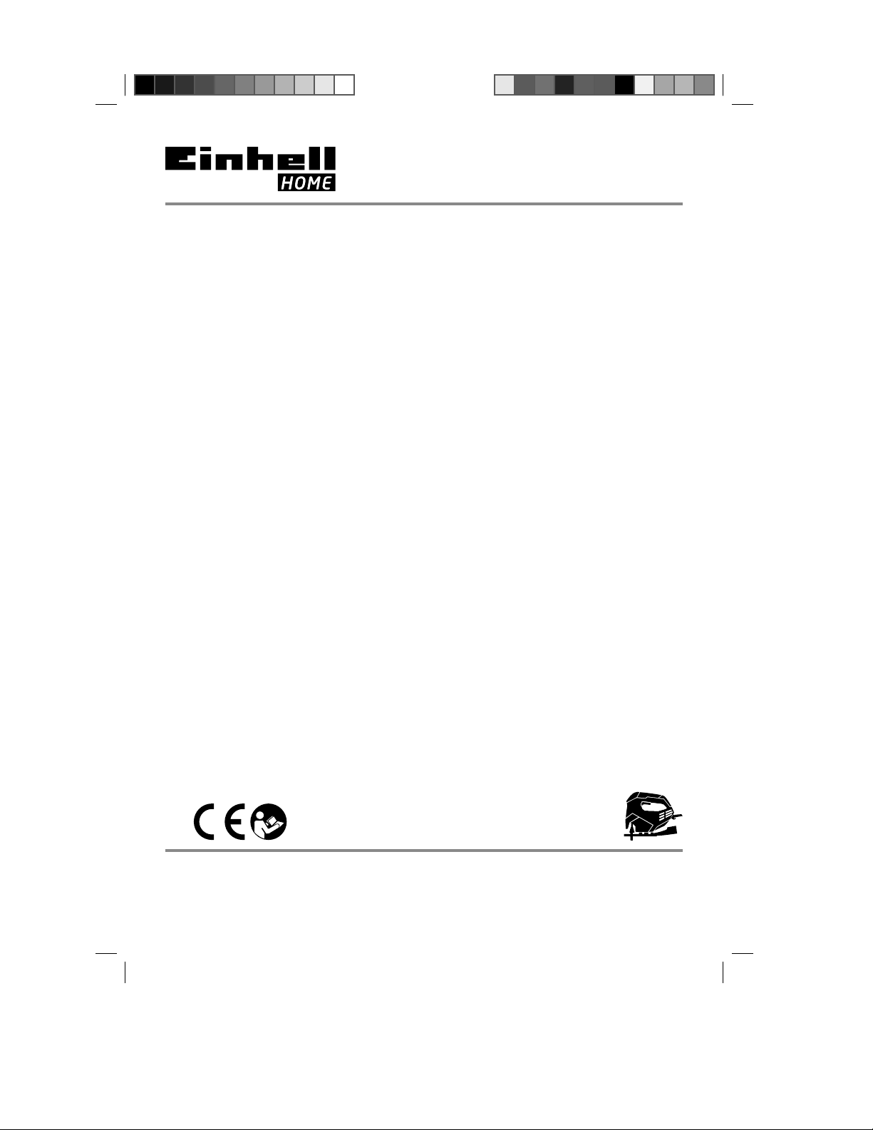
2.1 Gerätebeschreibung (Bild 1-3)
1. Drehzahlregler
2. Feststellknopf
3. Ein-/Ausschalter
4. Netzkabel
5. Adapter für Spanabsaugung
6. Schalter für Staub-Blas-funktion
7. Verstellbarer Sägeschuh
8. Umschalter für Pendelhub
9. Gradskala für Sägeschuh
10. Führungsrolle
11. Parallelanschlag
12. Sägeblatt
13. Feststellschrauben für Parallelanschlag
14. Sägeblattaufnahme
15. Schutzabdeckung
16. Feststellhebel für Sägeschuh
17. Splitterschutz
2.2 Lieferumfang
Bitte überprüfen Sie die Vollständigkeit des Artikels anhand des beschriebenen Lieferumfangs.
Bei Fehlteilen wenden Sie sich bitte spätestens
innerhalb von 5 Arbeitstagen nach Kauf des Artikels unter Vorlage eines gültigen Kaufbeleges an
unser Service Center oder an den nächstgelegenen zuständigen Baumarkt. Bitte beachten Sie
hierzu die Gewährleistungstabelle in den Garantiebestimmungen am Ende der Anleitung.
Öffnen Sie die Verpackung und nehmen Sie
•
das Gerät vorsichtig aus der Verpackung.
Entfernen Sie das Verpackungsmaterial so-
•
wie Verpackungs-/ und Transportsicherungen
(falls vorhanden).
Überprüfen Sie, ob der Lieferumfang vollstän-
•
dig ist.
Kontrollieren Sie das Gerät und die Zubehör-
•
teile auf Transportschäden.
Bewahren Sie die Verpackung nach Möglich-
•
keit bis zum Ablauf der Garantiezeit auf.
Achtung!
Gerät und Verpackungsmaterial sind kein
Kinderspielzeug! Kinder dürfen nicht mit
Kunststoff beuteln, Folien und Kleinteilen
spielen! Es besteht Verschluckungs- und Erstickungsgefahr!
Stichsäge
•
Parallelanschlag
•
Sägeblatt für Holz
•
Originalbetriebsanleitung
•
Sicherheitshinweise
•
3. Bestimmungsgemäße
Verwendung
Die Stichsäge ist zum Sägen von Holz, Metallen,
Buntmetallen und Kunststoff en unter Verwendung
des entsprechenden Sägeblatts bestimmt.
Die Maschine darf nur nach ihrer Bestimmung
verwendet werden. Jede weitere darüber hinausgehende Verwendung ist nicht bestimmungsgemäß. Für daraus hervorgerufene Schäden oder
Verletzungen aller Art haftet der Benutzer/Bediener und nicht der Hersteller.
- 7 -
Anl_TH_JS_85_SPK1.indb 7Anl_TH_JS_85_SPK1.indb 7 24.10.12 10:2324.10.12 10:23
Page 8

D
Bitte beachten Sie, dass unsere Geräte bestimmungsgemäß nicht für den gewerblichen, handwerklichen oder industriellen Einsatz konstruiert
wurden. Wir übernehmen keine Gewährleistung,
wenn das Gerät in Gewerbe-, Handwerks- oder
Industriebetrieben sowie bei gleichzusetzenden
Tätigkeiten eingesetzt wird.
4. Technische Daten
Netzspannung:................................230 V~ 50 Hz
Leistungsaufnahme: ...................................620 W
Hubzahl: .....................................800 - 3.000 min
Hubhöhe: .................................................. 20 mm
Schnitttiefe Holz: ....................................... 85 mm
Schnitttiefe Kunststoff : .............................. 12 mm
Schnitttiefe Eisen: ....................................... 8 mm
Gehrungschnitt: ............ bis 45° (links und rechts)
Schutzklasse: ................................................II /
Gewicht: ......................................................2,1 kg
Geräusch und Vibration
Die Geräusch- und Vibrationswerte wurden entsprechend EN 60745 ermittelt.
Schalldruckpegel L
Unsicherheit K
Schallleistungspegel L
Unsicherheit K
Tragen Sie einen Gehörschutz.
Die Einwirkung von Lärm kann Gehörverlust bewirken.
Schwingungsgesamtwerte (Vektorsumme dreier
Richtungen) ermittelt entsprechend EN 60745.
Schneiden von Holz
Schwingungsemissionswert a
Unsicherheit K = 1,5 m/s
Schneiden von Blech
Schwingungsemissionswert ah = 9,3 m/s
Unsicherheit K = 1,5 m/s
.............................. 90 dB(A)
pA
............................................ 3 dB
pA
WA
...................... 101 dB(A)
WA
........................................... 3 dB
2
2
= 11,0 m/s
h
2
2
Warnung!
Der angegebene Schwingungsemissionswert ist
nach einem genormten Prüfverfahren gemessen
worden und kann sich, abhängig von der Art und
Weise, in der das Elektrowerkzeug verwendet
wird, ändern und in Ausnahmefällen über dem
angegebenen Wert liegen.
Der angegebene Schwingungsemissionswert
kann zum Vergleich eines Elektrowerkzeuges mit
einem anderen verwendet werden.
Der angegebene Schwingungsemissionswert
kann auch zu einer einleitenden Einschätzung der
-1
Beeinträchtigung verwendet werden.
Beschränken Sie die Geräuschentwicklung
und Vibration auf ein Minimum!
Verwenden Sie nur einwandfreie Geräte.
•
Warten und reinigen Sie das Gerät regelmä-
•
쓑
ßig.
Passen Sie Ihre Arbeitsweise dem Gerät an.
•
Überlasten Sie das Gerät nicht.
•
Lassen Sie das Gerät gegebenenfalls über-
•
prüfen.
Schalten Sie das Gerät aus, wenn es nicht
•
benutzt wird.
Tragen Sie Handschuhe.
•
Restrisiken
Auch wenn Sie dieses Elektrowerkzeug
vorschriftsmäßig bedienen, bleiben immer
Restrisiken bestehen. Folgende Gefahren
können im Zusammenhang mit der Bauweise
und Ausführung dieses Elektrowerkzeuges
auftreten:
1. Lungenschäden, falls keine geeignete Staub-
schutzmaske getragen wird.
2. Gehörschäden, falls kein geeigneter Gehör-
schutz getragen wird.
3. Gesundheitsschäden, die aus Hand-Arm-
Schwingungen resultieren, falls das Gerät
über einen längeren Zeitraum verwendet wird
oder nicht ordnungsgemäß geführt und gewartet wird.
- 8 -
Anl_TH_JS_85_SPK1.indb 8Anl_TH_JS_85_SPK1.indb 8 24.10.12 10:2324.10.12 10:23
Page 9

D
5. Vor Inbetriebnahme
Überzeugen Sie sich vor dem Anschließen, dass
die Daten auf dem Typenschild mit den Netzdaten
übereinstimmen.
Ziehen Sie immer den Netzstecker, bevor Sie
Einstellungen am Gerät vornehmen.
5.1 Schutzabdeckung (Bild 2/Pos. 15)
Die Schutzabdeckung (15) schützt vor ver-
•
sehentlichem Berühren des Sägeblattes (12)
und lässt dennoch den Blick auf den Schnittbereich zu.
Die Schutzabdeckung (15) muss beim Aus-
•
führen von Schnitten immer montiert sein.
Die Schutzabdeckung kann bei Einstellarbei-
•
ten abgenommen werden.
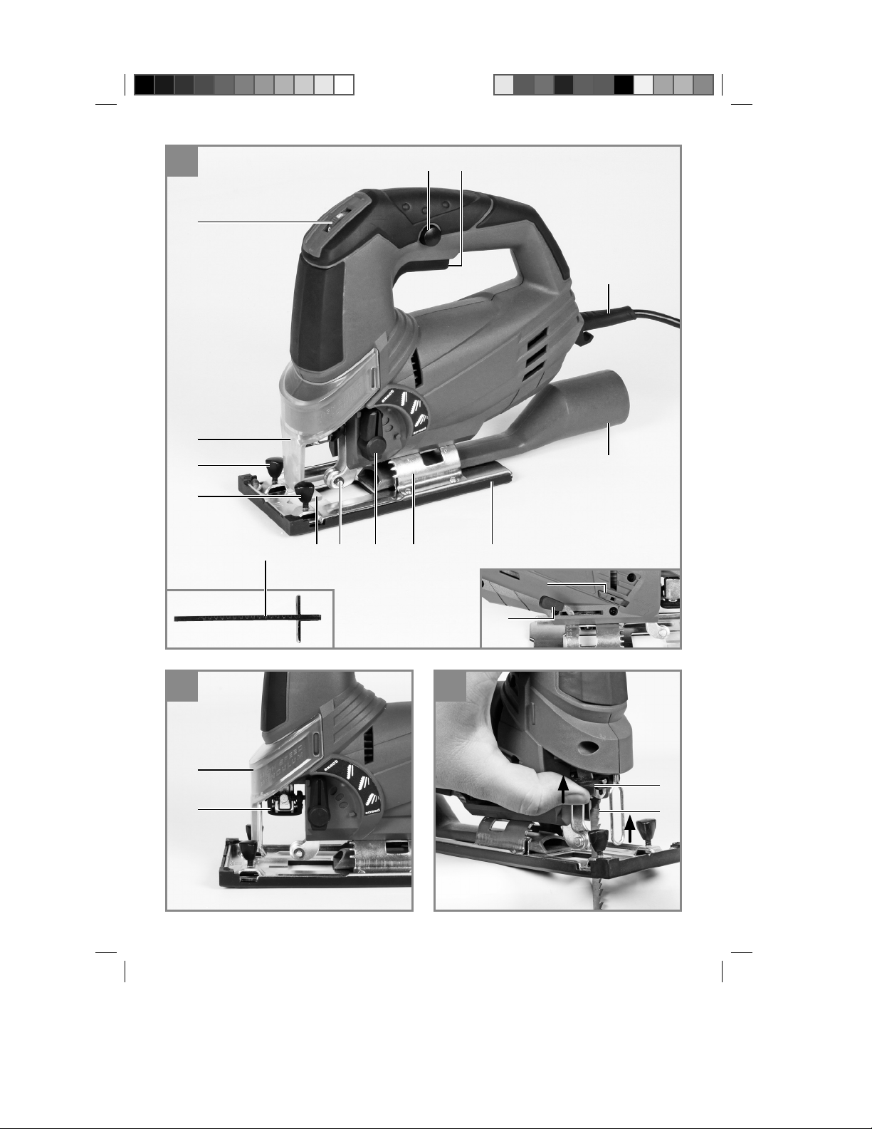
5.2 Sägeblattwechsel (Bilder 3-4/Pos. 12)
Achtung!
Sie können Sägeblätter ohne Benutzung
•
weiterer Werkzeuge einsetzen oder austauschen.
Ziehen Sie den Netzstecker, bevor Sie ein
•
Sägeblatt einsetzen oder austauschen.
Stellen Sie den Umschalter für Pendelhub (8)
•
auf Position D (siehe Bild 10).
Die Zähne des Sägeblattes sind sehr scharf.
•
Schutzabdeckung (15) entnehmen
•
Die Aufnahme für Sägeblatt (14) drücken und
•
das Sägeblatt (12) bis zum Anschlag in die
Sägeblattaufnahme (14) führen (Bild 3). Die
Sägeblattzahnung muss nach vorne zeigen.
Die Aufnahme für das Sägeblatt (14) wieder
•
zurück gleiten lassen. Das Sägeblatt (12)
muss in der Führungsrolle (10) sitzen (Bild 4).
Überprüfen ob das Sägeblatt (12) fest in der
•
Aufnahme sitzt.
Das Entfernen des Sägeblattes erfolgt in um-
•
gekehrter Reihenfolge.
5.3 Montage des Parallelanschlages
(Bild 5/Pos. 11)
Der Parallelanschlag (11) erlaubt es Ihnen
•
parallele Schnitte auszuführen.
Lockern Sie die beiden am Sägeschuh (7)
•
gelegenen Feststellschrauben (13).
Parallelanschlag (11) nun in die Führungen
•
am Sägeschuh (7) einschieben. Sie können
den Parallelanschlag (11) an der linken oder
an der rechten Seite des Gerätes einsetzen.
Die Führungsleiste stets nach unten ausrich-
•
ten. Setzen Sie mit Hilfe der Messskala des
Parallelanschlages (11) den benötigten Ab-
stand fest und ziehen Sie die Feststellschrauben (13) wieder an.
5.4 Einstellen des Sägeschuhs für Gehrungsschnitte (Bild 6)
Den Festellhebel (16) am Sägeschuh lösen.
•
Den Sägeschuh (7) leicht nach hinten ziehen.
•
Der Sägeschuh kann nun bis zu 45° nach
links oder rechts geneigt werden.
Wird der Sägeschuh (7) wieder nach vorn
•
geschoben, so funktioniert dies jeweils nur
in den bei 0°, 15°, 30° und 45° befindlichen
Raststellungen, welche an der Gradskala für
Sägeschuh (9) markiert sind. Sägeschuh in
entsprechende Position bringen und den Festellhebel (16) anziehen.
Der Sägeschuh (7) kann jedoch auch ohne
•
weiteres auf ein anderes Winkelmaß eingestellt werden. Sägeschuh (7) hierzu nach hinten schieben, gewünschten Winkel einstellen
und den Festellhebel (16) wieder anziehen.
Achtung! Bei Gehrungsschnitten müssen die
Feststellschrauben für Parallelanschlag (13) und
der Splitterschutz (17) enfernt werden.
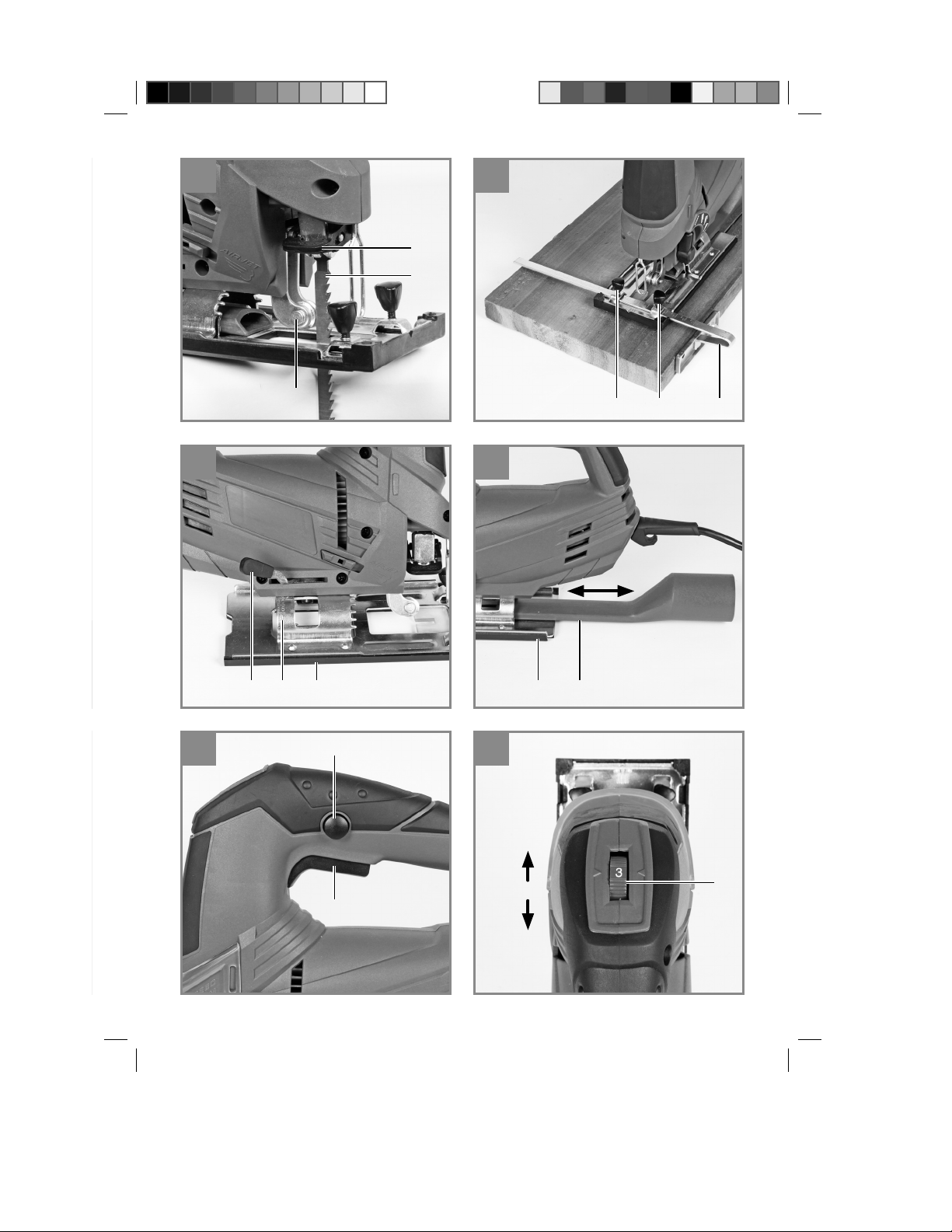
5.5 Adapter für Spanabsaugung
(Bild 7/Pos. 5)
Schließen Sie Ihre Stichsäge mit dem Adap-
•
ter für Spanabsaugung (5) an einen Staubsauger an. Sie erreichen damit eine optimale
Staubabsaugung vom Werkstück. Die Vorteile: Sie schonen sowohl das Gerät als auch
Ihre eigene Gesundheit. Ihr Arbeitsbereich
bleibt außerdem sauberer und sicherer.
Bei der Arbeit entstehender Staub kann ge-
•
fährlich sein. Bitte beachten Sie hierzu die
Sicherheitshinweise.
Setzen Sie den Adapter (5) wie in Abbildung
•
7 dargestellt ein. Der Adapter (5) muss hörbar
einrasten, so dass er fest im Sägeschuh (7)
sitzt. Bei Gehrungsschnitten kann der Adapter für Spanabsaugung (5) nicht verwendet
werden.
Stecken Sie den Saugschlauch ihres Staub-
•
saugers auf die Öffnung des Adapters (5).
Achten Sie auf luftdichte Verbindung der Geräte.
- 9 -
Anl_TH_JS_85_SPK1.indb 9Anl_TH_JS_85_SPK1.indb 9 24.10.12 10:2324.10.12 10:23
Page 10

D
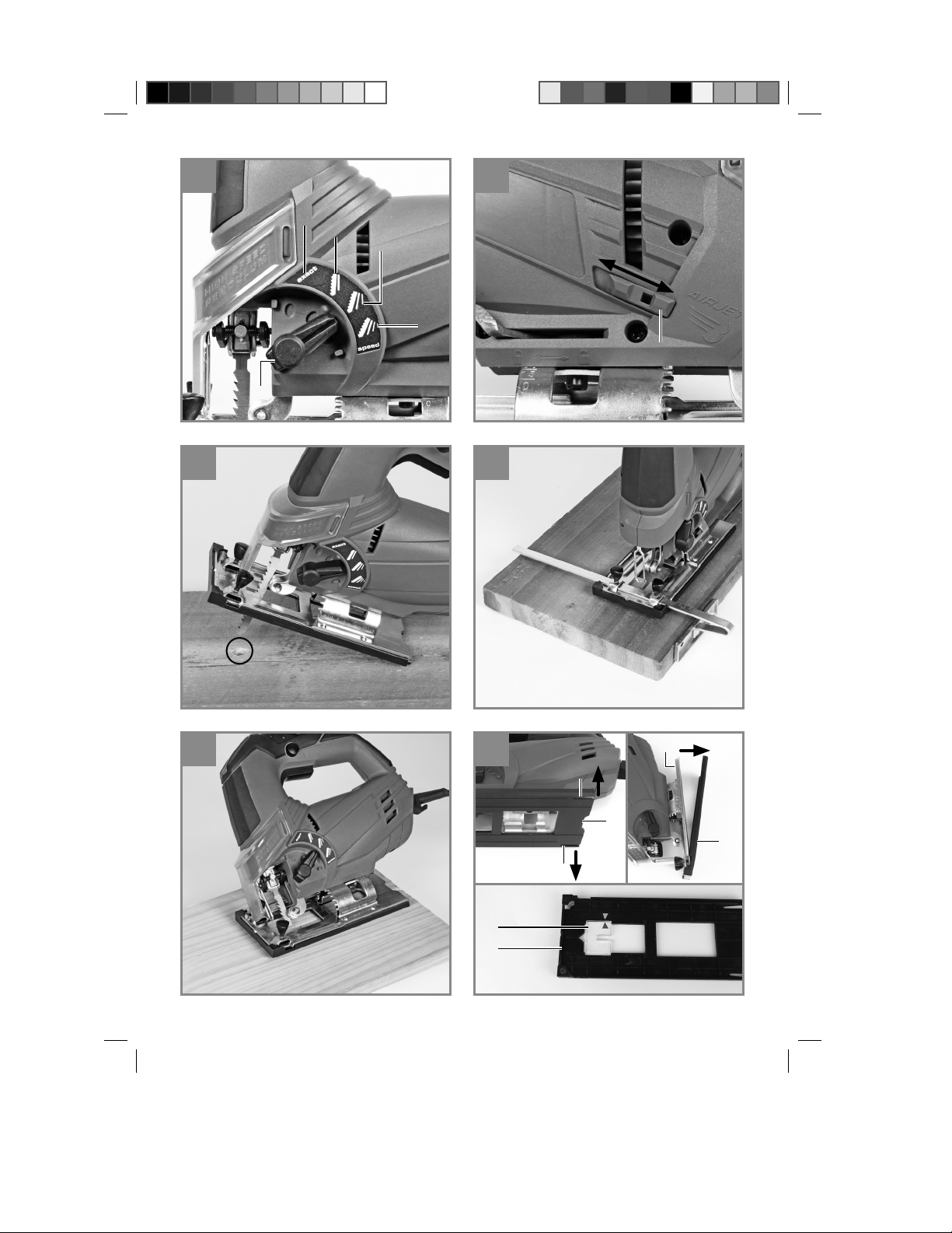
5.6 Splitterschutz (Bild 15/Pos. 17)
Der Splitterschutz (17) sorgt dafür, daß das zu
bearbeitende Material während des Sägens nicht
absplittert oder ausbricht. Um den Splitterschutz
(17) einzusetzen, gehen Sie wie folgt vor:
1. Biegen Sie die beiden Nasen (a) am Sägeschuhschutz (b) leicht nach außen und heben
Sie den Sägeschuhschutz an.
2. Entnehmen Sie den Sägeschuhschutz (b)
vom Sägeschuh (7) wie in Bild 15 gezeigt.
3. Legen Sie den Splitterschutz (17) in den
Sägeschuhschutz (b) ein. Achten Sie dabei
darauf, daß die Pfeile am Splitterschutz und
am Sägeschuhschutz wie in Bild 15 übereinstimmen.
Nun kann der Sägeschuhschutz (b) wieder auf
den Sägeschuh (7) aufgesetzt werden. Gehen
Sie dabei in umgekehrter Reihenfolge vor.
Achtung! Der Splitterschutz (17) kann nur bei
0° Schnitten verwenden werden und muß bei
Gehrungsschnitten bis 45° entfernt werden!
6. Bedienung
6.1 Ein-/ Ausschalter (Bild 8/Pos. 3)
Einschalten:
Ein/Ausschalter (3) drücken
Ausschalten:
Ein/Ausschalter (3) loslassen
6.2 Feststellknopf (Bild 8/Pos. 2)
Mit dem Feststellknopf (2) kann der Ein-/ Ausschalter (3) im Betrieb arretiert werden. Zum Ausschalten Ein-/ Ausschalter (3) kurz eindrücken.
6.3 Elektronische Drehzahlvorwahl
(Bild 9/Pos. 1)
Mit dem Drehzahlregler kann die gewünschte
Drehzahl voreingestellt werden. Drehen Sie den
Drehzahlregler in PLUS-Richtung, um die Drehzahl zu erhöhen, drehen Sie den Drehzahlregler
in MINUS-Richtung um die Drehzahl zu verringern. Die geeignete Hubzahl ist vom jeweiligen
Werkstoff und den Arbeitsbedingungen abhängig.
Die allgemeinen Regeln für die Schnittgeschwindig-keit bei spanabhebenden Arbeiten sind auch
hier gültig.
Mit feinen Sägeblättern können Sie im Allgemeinen mit höherer Hubzahl arbeiten; gröbere Sägeblätter verlangen nach niedrigeren Geschwindigkeiten.
Position 1-2 = Niedrige Hubzahl (für Stahl)
Position 3-4 = Mittlere Hubzahl (für Stahl, Weich-
metall, Kuststoff )
Position 5-6 = Hohe Hubzahl (für Weichholz,
Hartholz, Weichmetall, Kunststoff )
6.4 Einstellung Pendelhub (Bild 10/Pos. 8)
Am Umschalter für Pendelhub (8) kann die
•
stärke der Pendelbewegung des Sägeblattes
(12) beim Hub eingestellt werden.
Sie können Schnittgeschwindigkeit, Schnitt-
•
leistung und Schnittbild an das zu bearbeitende Werkstück anpassen.
Stellen Sie den Umschalter für Pendelhub (8) auf
eine der folgenden Positionen:
Position A = Keine Pendelung
Material: Gummi, Keramik, Aluminium, Stahl
Anmerkung: Für feine und saubere Schnittkan-
ten, dünne Materailien (z.B. Bleche) und harte
Materalien.
Position B = Kleine Pendelung
Material: Kunststoff , Holz, Aluminium
Anmerkung: Für harte Materalien
Position C = Mittlere Pendelung
Material: Holz
Position D = Große Pendelung
Material: Holz
Anmerkung: Für weiche Materalien und Sägen
in Faserrichtung
Die beste Kombination von Drehzahl- und Pendelhubeinstellung ist vom zu bearbeitenden Material abhängig. Wir empfehlen die ideale Einstellung stets anhand eines Probeschnittes an einem
Abfallstück zu ermitteln.
- 10 -
Anl_TH_JS_85_SPK1.indb 10Anl_TH_JS_85_SPK1.indb 10 24.10.12 10:2324.10.12 10:23
Page 11

D
6.5 Staub-Blas-Funktion (Bild 11 / Pos. 6)
Durch einen zuschaltbaren Luftstrom bleibt die
Schnittlinie frei von Staub und Spänen.
Zum Einschalten muss der Schalter für
•
Staub-Blas-Funktion (6) nach vorn geschoben werden.
Zum Ausschalten muss der Schalter für
•
Staub-Blas-Funktion (6) wieder zurück geschoben werden.
6.6 Ausführen von Schnitten
Stellen Sie sicher, dass der Ein-/Ausschalter
•
(3) nicht eingedrückt ist. Verbinden Sie erst
dann den Netzstecker mit einer geeigneten
Steckdose.
Schalten Sie die Stichsäge nur mit eingesetz-
•
tem Sägeblatt ein.
Verwenden Sie nur einwandfreie Sägeblätter.
•
Wechseln Sie stumpfe, verbogene oder rissige Sägeblätter sofort aus.
Platzieren Sie den Sägefuß flach auf dem zu
•
bearbeitendem Werkstück. Schalten Sie die
Stichsäge ein.
Lassen Sie das Sägeblatt anlaufen, bis es die
•
volle Geschwindigkeit erreicht hat. Führen Sie
dann das Sägeblatt langsam an der Schnittlinie entlang. Üben Sie dabei nur leichten
Druck auf das Sägeblatt aus.
Beim Sägen von Metall sollte die Schnittlinie
•
mit einem geeigneten Kühlmittel bestrichen
werden.
6.7 Aussägen von Bereichen (Bild 12)
Bohren Sie mit einer Bohrmaschine innerhalb
des auszusägenden Bereiches ein 10 mm großes
Loch. Führen Sie das Sägeblatt in dieses Loch
ein und beginnen Sie, den gewünschten Bereich
auszusägen.
6.8 Ausführen von Parallelschnitten
Parallelanschlag montieren und entspre-
•
chend justieren (siehe Punkt 5.3).
Hinweise in Punkt 6.6 beachten.
•
Schnitt wie in Bild 13 dargestellt ausführen.
•
7. Austausch der
Netzanschlussleitung
Wenn die Netzanschlussleitung dieses Gerätes
beschädigt wird, muss sie durch den Hersteller
oder seinen Kundendienst oder eine ähnlich qualifi zierte Person ersetzt werden, um Gefährdun-
gen zu vermeiden.
8. Reinigung, Wartung und
Ersatzteilbestellung
Ziehen Sie vor allen Reinigungsarbeiten den
Netzstecker.
8.1 Reinigung
Halten Sie Schutzvorrichtungen, Luftschlitze
•
und Motorengehäuse so staub- und schmutzfrei wie möglich. Reiben Sie das Gerät mit
einem sauberen Tuch ab oder blasen Sie es
mit Druckluft bei niedrigem Druck aus.
Wir empfehlen, dass Sie das Gerät direkt
•
nach jeder Benutzung reinigen.
Reinigen Sie das Gerät regelmäßig mit einem
•
feuchten Tuch und etwas Schmierseife. Verwenden Sie keine Reinigungs- oder Lösungsmittel; diese könnten die Kunststoffteile des
Gerätes angreifen. Achten Sie darauf, dass
kein Wasser in das Geräteinnere gelangen
kann. Das Eindringen von Wasser in ein Elektrogerät erhöht das Risiko eines elektrischen
Schlages.
8.2 Kohlebürsten
Bei übermäßiger Funkenbildung lassen Sie die
Kohlebürsten durch eine Elektrofachkraft überprüfen. Achtung! Die Kohlebürsten dürfen nur von
einer Elektrofachkraft ausgewechselt werden.
8.3 Wartung
Im Geräteinneren befi nden sich keine weiteren zu
wartenden Teile.
6.9 Gehrungsschnitt (Bild 14)
Winkel am Sägeschuh entsprechend einstel-
•
len (siehe Punkt 5.4)
Hinweise in Punkt 6.6 beachten.
•
Schnitt wie in Bild 14 dargestellt ausführen.
•
Anl_TH_JS_85_SPK1.indb 11Anl_TH_JS_85_SPK1.indb 11 24.10.12 10:2324.10.12 10:23
8.4 Ersatzteilbestellung:
Bei der Ersatzteilbestellung sollten folgende Angaben gemacht werden;
Typ des Gerätes
•
Artikelnummer des Gerätes
•
Ident-Nummer des Gerätes
•
Ersatzteilnummer des erforderlichen Ersatz-
•
teils
Aktuelle Preise und Infos fi nden Sie unter
www.isc-gmbh.info
- 11 -
Page 12

9. Entsorgung und
Wiederverwertung
Das Gerät befi ndet sich in einer Verpackung um
Transportschäden zu verhindern. Diese Verpackung ist Rohstoff und ist somit wieder verwend-
bar oder kann dem Rohstoff kreislauf zurückge-
führt werden. Das Gerät und dessen Zubehör
bestehen aus verschiedenen Materialien, wie
z.B. Metall und Kunststoff e. Defekte Geräte ge-
hören nicht in den Hausmüll. Zur fachgerechten
Entsorgung sollte das Gerät an einer geeigneten
Sammelstellen abgegeben werden. Wenn Ihnen
keine Sammelstelle bekannt ist, sollten Sie bei
der Gemeindeverwaltung nachfragen.
10. Lagerung
Lagern Sie das Gerät und dessen Zubehör an
einem dunklen, trockenen und frostfreiem sowie
für Kinder unzugänglichem Ort. Die optimale
Lagertemperatur liegt zwischen 5 und 30 ˚C.
Bewahren Sie das Elektrowerkzeug in der Originalverpackung auf.
D
- 12 -
Anl_TH_JS_85_SPK1.indb 12Anl_TH_JS_85_SPK1.indb 12 24.10.12 10:2324.10.12 10:23
Page 13

D
Nur für EU-Länder
Werfen Sie Elektrowerkzeuge nicht in den Hausmüll!
Gemäß europäischer Richtlinie 2002/96/EG über Elektro- und Elektronik-Altgeräte und Umsetzung in
nationales Recht müssen verbrauchte Elektrowerkzeuge getrennt gesammelt werden und einer umweltgerechten Wiederverwertung zugeführt werden.
Recycling-Alternative zur Rücksendeauff orderung:
Der Eigentümer des Elektrogerätes ist alternativ anstelle Rücksendung zur Mitwirkung bei der sachgerechten Verwertung im Falle der Eigentumsaufgabe verpfl ichtet. Das Altgerät kann hierfür auch einer
Rücknahmestelle überlassen werden, die eine Beseitigung im Sinne der nationalen Kreislaufwirtschafts- und Abfallgesetze durchführt. Nicht betroff en sind den Altgeräten beigefügte Zubehörteile und
Hilfsmittel ohne Elektrobestandteile.
Der Nachdruck oder sonstige Vervielfältigung von Dokumentation und Begleitpapieren der Produkte,
auch auszugsweise, ist nur mit ausdrücklicher Zustimmung der iSC GmbH zulässig.
Technische Änderungen vorbehalten
- 13 -
Anl_TH_JS_85_SPK1.indb 13Anl_TH_JS_85_SPK1.indb 13 24.10.12 10:2324.10.12 10:23
Page 14

D
Garantiebestimmungen
Die Fa. iSC GmbH bzw. der zuständige Baumarkt garantiert die Behebung von Mängeln bzw. den Geräteaustausch entsprechend der unten stehenden Übersicht, wobei die gesetzlichen Gewährleistungsansprüche unberührt bleiben.
Kategorie Beispiel Garantieleistung
Mängel an Material oder Konstruktion
Verschleißteile* Kohlebürsten, Führungsrollen 6 Monate
Verbrauchsmaterial/
Verbrauchsteile*
Fehlteile 5 Arbeitstage
* nicht zwingend im Lieferumfang enthalten!
Bezüglich Verschleißteilen, Verbrauchsmaterial und Fehlteilen garantiert die Fa. iSC GmbH bzw. der
zuständige Baumarkt eine Mängelbehebung bzw. eine Nachlieferung nur, wenn der Mangel innerhalb
von 24h (Verbrauchsmaterial), 5 Arbeitstagen (Fehlteilen) oder 6 Monaten (Verschleißteile) nach Kauf
angezeigt und das Kaufdatum durch Kaufbeleg nachgewiesen wird.
Bei Mängeln an Material oder Konstruktion, bitten wir Sie im Garantiefall das Gerät zusammen mit beiliegender Gerätekarte einzureichen und diese vollständig auszufüllen. Wichtig ist hierbei eine genaue
Fehlerbeschreibung anzugeben.
Sägeblätter Garantie nur bei Sofortdefekt
24 Monate
(24h nach Kauf / Kaufbelegdatum)
Beantworten Sie hierfür folgende Fragen:
Hat das Gerät bereits einmal funktioniert oder war es von Anfang an defekt?
•
Ist Ihnen vor dem Auftreten des Defektes etwas aufgefallen (Symptom vor Defekt)?
•
Welche Fehlfunktion weist das Gerät Ihrer Meinung nach auf (Hauptsymptom)?
•
Beschreiben Sie diese Fehlfunktion.
- 14 -
Anl_TH_JS_85_SPK1.indb 14Anl_TH_JS_85_SPK1.indb 14 24.10.12 10:2324.10.12 10:23
Page 15

D
Garantieurkunde
Sehr geehrte Kundin, sehr geehrter Kunde,
unsere Produkte unterliegen einer strengen Qualitätskontrolle. Sollte dieses Gerät dennoch einmal nicht
einwandfrei funktionieren, bedauern wir dies sehr und bitten Sie, sich an unseren Servicedienst unter
der auf dieser Garantiekarte angegebenen Adresse zu wenden. Gern stehen wir Ihnen auch telefonisch
über die untenangegebene Servicerufnummer zur Verfügung. Für die Geltendmachung von Garantieansprüchen gilt folgendes:
1. Diese Garantiebedingungen regeln zusätzliche Garantieleistungen. Ihre gesetzlichen Gewährleis-
tungsansprüche werden von dieser Garantie nicht berührt. Unsere Garantieleistung ist für Sie
kostenlos.
2. Die Garantieleistung erstreckt sich ausschließlich auf Mängel, die auf Material- oder Herstellungs-
fehler zurückzuführen sind und ist auf die Behebung dieser Mängel bzw. den Austausch des Gerätes beschränkt. Bitte beachten Sie, dass unsere Geräte bestimmungsgemäß nicht für den gewerblichen, handwerklichen oder industriellen Einsatz konstruiert wurden. Ein Garantievertrag kommt
daher nicht zustande, wenn das Gerät in Gewerbe-, Handwerks- oder Industriebetrieben sowie bei
gleichzusetzenden Tätigkeiten eingesetzt wird.
Von unserer Garantie sind ferner Ersatzleistungen für Transportschäden, Schäden durch Nichtbe-
achtung der Montageanleitung oder aufgrund nicht fachgerechter Installation, Nichtbeachtung der
Gebrauchsanleitung (wie durch z.B. Anschluss an eine falsche Netzspannung oder Stromart), missbräuchliche oder unsachgemäße Anwendungen (wie z.B. Überlastung des Gerätes oder Verwendung von nicht zugelassenen Einsatzwerkzeugen oder Zubehör), Nichtbeachtung der Wartungsund Sicherheitsbestimmungen, Eindringen von Fremdkörpern in das Gerät (wie z.B. Sand, Steine
oder Staub), Gewaltanwendung oder Fremdeinwirkungen (wie z. B. Schäden durch Herunterfallen)
sowie durch verwendungsgemäßen, üblichen Verschleiß ausgeschlossen. Dies gilt insbesondere
für Akkus, auf die wir dennoch eine Garantiezeit von 12 Monaten gewähren. Der Garantieanspruch
erlischt, wenn an dem Gerät bereits Eingriff e vorgenommen wurden.
3. Die Garantiezeit beträgt 2 Jahre und beginnt mit dem Kaufdatum des Gerätes. Garantieansprüche
sind vor Ablauf der Garantiezeit innerhalb von zwei Wochen, nachdem Sie den Defekt erkannt
haben, geltend zu machen. Die Geltendmachung von Garantieansprüchen nach Ablauf der Garantiezeit ist ausgeschlossen. Die Reparatur oder der Austausch des Gerätes führt weder zu einer
Verlängerung der Garantiezeit noch wird eine neue Garantiezeit durch diese Leistung für das Gerät
oder für etwaige eingebaute Ersatzteile in Gang gesetzt. Dies gilt auch bei Einsatz eines Vor-OrtServices.
4. Für die Geltendmachung Ihres Garantieanspruches übersenden Sie bitte das defekte Gerät porto-
frei an die unten angegebene Adresse. Fügen Sie den Verkaufsbeleg im Original oder einen sonstigen datierten Kaufnachweis bei. Bitte bewahren Sie deshalb den Kassenbon als Nachweis gut auf!
Beschreiben Sie uns bitte den Reklamationsgrund möglichst genau. Ist der Defekt des Gerätes von
unserer Garantieleistung erfasst, erhalten Sie umgehend ein repariertes oder neues Gerät zurück.
Selbstverständlich beheben wir gegen Erstattung der Kosten auch gerne Defekte am Gerät, die vom
Garantieumfang nicht oder nicht mehr erfasst sind. Dazu senden Sie das Gerät bitte an unsere Serviceadresse.
Für Verschleiß-/Verbrauchs- und Fehlteile verweisen wir auf die Einschränkungen dieser Garantie gemäß den Garantiebestimmungen dieser Bedienungsanleitung.
iSC GmbH · Eschenstraße 6 · 94405 Landau/Isar (Deutschland)
Telefon: +49 [0] 180 5 120 509 · Telefax +49 [0] 180 5 835 830
(Festnetzpreis: 14 ct/min, Mobilfunkpreise maximal: 42 ct/min)
Außerhalb Deutschlands fallen stattdessen Gebühren für ein reguläres Gespräch ins dt. Festnetz an.
E-Mail: info@isc-gmbh.info · Internet: www.isc-gmbh.info
- 15 -
Anl_TH_JS_85_SPK1.indb 15Anl_TH_JS_85_SPK1.indb 15 24.10.12 10:2324.10.12 10:23
Page 16
Garantie JA NEIN Kaufbeleg-Nr. / Datum:
1
3
Fehlerbeschreibung und Art.-Nr. und I.-Nr. angeben l
4
Garantiefall JA/NEIN ankreuzen sowie Kaufbeleg-Nr. und Datum angeben und eine Kopie des Kaufbeleges beilegen
4
Service Hotline kontaktieren oder bei iSC-Webadresse anmelden - es wird Ihnen eine Retourennummer zugeteilt l
Sehr geehrte Kundin, sehr geehrter Kunde,
bitte beschreiben Sie uns die von Ihnen festgestellte Fehlfunktion Ihres Gerätes als Grund Ihrer Beanstandung möglichst genau. Dadurch können wir für Sie Ihre Reklamation schneller bearbeiten
und Ihnen schneller helfen. Eine zu ungenaue Beschreibung mit Begriff en wie „Gerät funktioniert nicht“ oder „Gerät defekt“ verzögert hingegen die Bearbeitung erheblich.
D
PLZ: Ort:
3
Welcher Fehler ist aufgetreten (genaue Angabe): Art.-Nr.: I.-Nr.:
Straße / Nr.:
2
Name:
(Festnetzpreis: 14 ct/min, Mobilfunkpreise maximal: 42 ct/min; Außerhalb Deutschlands fallen stattdessen Gebühren für ein reguläres Gespräch ins dt. Festnetz an.)
1
Service Hotline: 01805 120 509 · www.isc-gmbh.info · Mo-Fr 8:00-18:00 Uhr
Mobil:
2
Ihre Anschrift eintragen
- 16 -
Anl_TH_JS_85_SPK1.indb 16Anl_TH_JS_85_SPK1.indb 16 24.10.12 10:2324.10.12 10:23
Telefon:
Retouren-Nr. iSC:
Page 17

GB
Table of contents
1. Safety regulations
2. Layout and items supplied
3. Proper use
4. Technical data
5. Before starting the equipment
6. Operation
7. Replacing the power cable
8. Cleaning, maintenance and ordering of spare parts
9. Disposal and recycling
10. Storage
- 17 -
Anl_TH_JS_85_SPK1.indb 17Anl_TH_JS_85_SPK1.indb 17 24.10.12 10:2324.10.12 10:23
Page 18

GB
Caution - Read the operating instructions to reduce the risk of inquiry
Wear ear-muff s. The impact of noise can cause damage to hearing.
Wear a breathing mask. Dust which is injurious to health can be generated when working on wood
and other materials. Never use the device to work on any materials containing asbestos!
Wear safety goggles. Sparks generated during working or splinters, chips and dust emitted by the device can cause loss of sight.
- 18 -
Anl_TH_JS_85_SPK1.indb 18Anl_TH_JS_85_SPK1.indb 18 24.10.12 10:2324.10.12 10:23
Page 19

GB
Important!
When using the equipment, a few safety precautions must be observed to avoid injuries and
damage. Please read the complete operating
instructions and safety regulations with due care.
Keep this manual in a safe place, so that the information is available at all times. If you give the
equipment to any other person, hand over these
operating instructions and safety regulations as
well. We cannot accept any liability for damage
or accidents which arise due to a failure to follow
these instructions and the safety instructions.
1. Safety regulations
The corresponding safety information can be
found in the enclosed booklet.
Caution!
Read all safety regulations and instructions.
Any errors made in following the safety regulations and instructions may result in an electric
shock, fi re and/or serious injury.
Keep all safety regulations and instructions
in a safe place for future use.
2. Layout and items supplied
2.1 Layout (Fig. 1-3)
1. Speed controller
2. Locking button
3. On/Off switch
4. Power cable
5. Adapter for dust extraction system
6. Switch for dust-blower function
7. Adjustable soleplate
8. Selector switch for pendulum action
9. Dial scale for soleplate
10. Guide roller
11. Parallel stop
12. Saw blade
13. Locking screws for parallel stop
14. Blade holder
15. Safety guard
16. Locking lever for soleplate
17. Splinter guard
2.2 Items supplied
Please check that the article is complete as specifi ed in the scope of delivery. If parts are missing,
please contact our service center or the nearest
branch of the DIY store where you made your
purchase at the latest within 5 work days after
purchasing the article and upon presentation of
a valid bill of purchase. Also, refer to the warranty
table in the warranty provisions at the end of the
operating instructions.
Open the packaging and take out the equip-
•
ment with care.
Remove the packaging material and any
•
packaging and/or transportation braces (if
available).
Check to see if all items are supplied.
•
Inspect the equipment and accessories for
•
transport damage.
If possible, please keep the packaging until
•
the end of the guarantee period.
Important!
The equipment and packaging material are
not toys. Do not let children play with plastic
bags, foils or small parts. There is a danger of
swallowing or suff ocating!
Jigsaw
•
Parallel stop
•
Saw blade for wood
•
Original operating instructions
•
Safety instructions
•
3. Proper use
The jigsaw is designed for sawing wood, metals,
non-ferrous metals and plastics using the appropriate saw blade.
The equipment is to be used only for its prescribed purpose. Any other use is deemed to be a
case of misuse. The user / operator and not the
manufacturer will be liable for any damage or injuries of any kind caused as a result of this.
Please note that our equipment has not been designed for use in commercial, trade or industrial
applications. Our warranty will be voided if the
machine is used in commercial, trade or industrial
businesses or for equivalent purposes.
- 19 -
Anl_TH_JS_85_SPK1.indb 19Anl_TH_JS_85_SPK1.indb 19 24.10.12 10:2324.10.12 10:23
Page 20

GB
4. Technical data
Mains voltage: ............................... 230 V ~ 50 Hz
Power consumption: .................................. 620 W
Stroke speed: ............................ 800 - 3,000 min
Stroke height: ........................................... 20 mm
Cutting depth, wood: ................................ 85 mm
Cutting depth, plastic: .............................. 12 mm
Cutting depth, iron: ..................................... 8 mm
Miter cut: ........................ up to 45° (left and right)
Protection class: ...........................................II /
Weight: .......................................................2.1 kg
Sound and vibration
Sound and vibration values were measured in
accordance with EN 60745.
sound pressure level ........................ 90 dB(A)
L
pA
K
uncertainty .............................................3 dB
pA
L
sound power level ........................ 101 dB(A)
WA
K
uncertainty .............................................3 dB
WA
Wear ear-muff s.
The impact of noise can cause damage to hearing.
Total vibration values (vector sum of three directions) determined in accordance with EN 60745.
Cutting wood
Vibration emission value a
K uncertainty = 1.5 m/s
= 11.0 m/s
h
2
Cutting sheet metal
Vibration emission value ah = 9.3 m/s
K uncertainty = 1.5 m/s
2
2
2
Warning!
The specifi ed vibration value was established in
accordance with a standardized testing method. It
may change according to how the electric equipment is used and may exceed the specifi ed value
in exceptional circumstances.
쓑
Keep the noise emissions and vibrations to a
minimum.
Only use appliances which are in perfect wor-
•
king order.
-1
Adapt your working style to suit the appliance.
•
Do not overload the appliance.
•
Have the appliance serviced whenever ne-
•
Service and clean the appliance regularly.
•
cessary.
Switch the appliance off when it is not in use.
•
Wear protective gloves.
•
Residual risks
Even if you use this electric power tool in
accordance with instructions, certain residual risks cannot be rules out. The following
hazards may arise in connection with the
equipment’s construction and layout:
1. Lung damage if no suitable protective dust
mask is used.
2. Damage to hearing if no suitable ear protection is used.
3. Health damage caused by hand-arm vibrations if the equipment is used over a prolonged period or is not properly guided and
maintained.
5. Before starting the equipment
Before you connect the equipment to the mains
supply make sure that the data on the rating plate
are identical to the mains data.
Always pull the power plug before making
adjustments to the equipment.
5.1 Safety guard (Fig. 2/Item 15)
The safety guard (15) protects the user from
•
accidentally touching the saw blade (12) but
still gives you an unobstructed view of the
cutting area.
The safety guard (15) must always be fitted
•
when carrying out cutting work.
The safety guard can be removed for carrying
•
out adjustments.
The specifi ed vibration value can be used to
compare the equipment with other electric power
tools.
The specifi ed vibration value can be used for initi-
al assessment of a harmful eff ect.
- 20 -
Anl_TH_JS_85_SPK1.indb 20Anl_TH_JS_85_SPK1.indb 20 24.10.12 10:2324.10.12 10:23
Page 21

GB
5.2 Changing the saw blade
(Figs. 3-4/Item 12)
Important.
You can fit or replace saw blades without
•
using any other tools.
Pull out the mains plug before you fit or repla-
•
ce a saw blade.
Set the selector switch for pendulum action
•
(8) to position D (see Fig. 10).
The teeth of the saw blade are very sharp!
•
Remove the safety guard (15).
•
Press the blade holder (14) and insert the
•
saw blade (12) into the blade holder (14) as
far as the stop (Fig. 3). The teeth on the saw
blade must be pointing forwards.
Allow the blade holder (14) to slide back to
•
starting position. The saw blade (12) must sit
in the guide roller (10) (Fig.4).
Check that the saw blade (12) is securely
•
mounted in the blade holder.
To remove the saw blade, follow the instruc-
•
tions above in reverse order.
5.3 Installing the parallel stop (Fig. 5/Item 11)
The parallel stop (11) enables you to saw
•
parallel cuts.
Undo the two locking screws (13) on the so-
•
leplate (7).
Now slide the parallel stop into the guides on
•
the soleplate (7). You can fit the parallel stop
(11) on either the left or right of the equipment.
The guide strip must always face downwards.
•
Set the required distance using the measurement scale on the parallel stop (11) and
tighten the locking screws (13) again.
5.4 Setting the soleplate for miter cuts (Fig. 6)
Undo the locking lever (16) on the soleplate.
•
Pull the sole plate (7) backwards slightly. The
•
soleplate can now be swiveled a maximum
45° to the left and right.
If the soleplate (7) is pushed back to the
•
front again it will only function in the locking
positions at 0°, 15°, 30° and 45°, which are
marked on the graduated scale for the soleplate (9). Move the soleplate into the required
position and refasten the locking lever (16).
However, the soleplate (7) is also easily set
•
to another angle. To do so, slide the soleplate
(7) backwards, set the desired angle and refasten the locking lever (16).
Important. For miter cuts you must remove the
locking screws for the parallel stop (13) and the
splinter guard (17).
5.5 Adapter for dust extraction system
(Fig. /Item 5)
Connect your jigsaw to a vacuum cleaner
•
using the adaptor for dust extraction (5). This
will provide excellent dust extraction on the
work piece. The benefits are that you will protect both the equipment and your own health.
Your work area will also be cleaner and safer.
Dust created when working may be dange-
•
rous. Refer to the section entitled “Safety
instructions”.
Fit the adapter (5) as shown in Fig. 7. The
•
adapter (5) must audibly engage to ensure
that it is secure in the soleplate (7). The adapter for chip extraction (5) cannot be used for
miter cuts.
Fit the vacuum tube of the vacuum cleaner
•
onto the adaptor opening (5). Check that the
connections are air-tight.
5.6 Splinter guard (Fig. 15/Item 17)
The splinter guard (17) ensures that the material
you want to cut does not splinter or crack during
sawing. To use the splinter guard (17), proceed
as follows:
1. Bend the two lugs (a) on the soleplate guard
(b) slightly outwards and raise the soleplate
guard.
2. Remove the soleplate guard (b) from the soleplate (7) as shown in Fig. 15.
3. Insert the splinter guard (17) into the soleplate guard (b). As you do so, make sure that
the arrows on the splinter guard and on the
soleplate guard coincide as shown in Fig. 15.
The soleplate guard (b) can now be placed on the
soleplate (7) again. Proceed in reverse order.
Important. The splinter guard (17) can be
used only for 0° cuts and must be removed
for miter cuts up to 45°!
- 21 -
Anl_TH_JS_85_SPK1.indb 21Anl_TH_JS_85_SPK1.indb 21 24.10.12 10:2324.10.12 10:23
Page 22

GB
6. Operation
6.1 On/Off switch (Fig. 8/Item 3)
To switch on:
Press the On/Off switch (3)
To switch off :
Release the On/Off switch (3)
6.2 Locking button (Fig. 8/Item 2)
You can lock the On/Off switch (3) using the lo-
cking button (2) when the equipment is in operation. To switch off the equipment, press the On/Off
switch (3) briefl y.
6.3 Electric speed selector (Fig. 9/Item 1)
You can pre-select the required speed with the
speed selector. Turn the speed selector in PLUS
director to increase the speed and turn the speed
selector in MINUS direction to reduce the speed.
The appropriate stroke speed depends on the
material you want to cut and on the working conditions. The general rules for cutting speeds in
metal also apply.
While you can generally use a higher speed with
fi ne saw blades, lower speeds are required for
coarse saw blades.
Position 1-2 = low stroke speed (for steel)
Position 3-4 = medium stroke speed (for steel,
soft metal, plastic)
Position 5-6 = high stroke speed (for softwood,
hardwood, soft metal, plastic)
6.4 Setting the pendulum action
(Fig. 10/Item 8)
The strength of the pendulum action of the
•
saw blade (12) can be adjusted using the selector switch for pendulum action (8).
You can adjust the cutting speed, cutting
•
performance and appearance of the cut to the
work piece you want to saw.
Set the selector switch for pendulum action (8) to
one of the following positions:
Position A = no pendulum action
Material: Rubber, ceramic, aluminium, steel
Please note: For fi ne clean cuts, thin materials
(e.g. sheet steel) and hard materials.
Position B = small pendulum action
Material: Plastic, wood, aluminium
Please note: For hard materials
Position C = medium pendulum action
Material: Wood
Position D = large pendulum action
Material: Wood
Please note: For soft materials and sawing along
the grain
The best combination of speed and pendulum
action depends on the material you want to saw.
We recommend you to make a trial cut on a waste
piece in order to check the ideal settings.
6.5 Dust-blower function (Fig. 11 / Item 6)
A current of air can be activated to keep the cutting line free of dust and chips.
To activate, slide the switch for the dust-
•
blower function (6) forwards.
To deactivate, slide the switch for the dust-
•
blower function (6) back again.
6.6 Making cuts
Ensure that the On/Off switch (3) is not de-
•
pressed. Only then should you connect the
mains plug to a suitable socket.
Do not switch on the jigsaw until you have
•
fitted a saw blade.
Use only saw blades that are in perfect con-
•
dition. Replace blunt, bent or cracked saw
blades immediately.
Place the saw foot flat on the work piece you
•
want to saw. Switch on the jigsaw.
Allow the saw blade to accelerate until it
•
reaches full speed. Then slowly move the saw
blade along the cutting line. Exert only gentle
pressure on the saw blade as you do so.
When cutting metal, apply a suitable coolant
•
along the line you want to cut.
6.7 Sawing out sections (Fig. 12)
Drill a 10 mm hole in the section you want to saw
out. Insert the saw blade into this hole and start to
saw out the required section.
6.8 Making parallel cuts
Mount the parallel stop and adjust as required
•
(see section 5.3).
Observe the instructions in section 6.6.
•
Cut as shown in Fig. 13.
•
- 22 -
Anl_TH_JS_85_SPK1.indb 22Anl_TH_JS_85_SPK1.indb 22 24.10.12 10:2324.10.12 10:23
Page 23

GB
6.9 Miter cuts (Fig. 14)
Set the angle on the soleplate (see section
•
5.4).
Observe the instructions in section 6.6.
•
Cut as shown in Fig. 14.
•
7. Replacing the power cable
If the power cable for this equipment is damaged,
it must be replaced by the manufacturer or its
after-sales service or similarly trained personnel
to avoid danger.
8. Cleaning, maintenance and
ordering of spare parts
Always pull out the mains power plug before starting any cleaning work.
8.1 Cleaning
Keep all safety devices, air vents and the
•
motor housing free of dirt and dust as far as
possible. Wipe the equipment with a clean
cloth or blow it with compressed air at low
pressure.
We recommend that you clean the device
•
immediately each time you have finished
using it.
Clean the equipment regularly with a moist
•
cloth and some soft soap. Do not use
cleaning agents or solvents; these could attack the plastic parts of the equipment. Ensure that no water can seep into the device. The
ingress of water into an electric tool increases
the risk of an electric shock.
8.4 Ordering replacement parts:
Please quote the following data when ordering
replacement parts:
Type of machine
•
Article number of the machine
•
Identification number of the machine
•
Replacement part number of the part required
•
For our latest prices and information please go to
www.isc-gmbh.info
9. Disposal and recycling
The equipment is supplied in packaging to prevent it from being damaged in transit. The raw
materials in this packaging can be reused or
recycled. The equipment and its accessories are
made of various types of material, such as metal
and plastic. Never place defective equipment in
your household refuse. The equipment should
be taken to a suitable collection center for proper
disposal. If you do not know the whereabouts of
such a collection point, you should ask in your
local council offi ces.
10. Storage
Store the equipment and accessories out of
children’s reach in a dark and dry place at above
freezing temperature. The ideal storage temperature is between 5 and 30 °C. Store the electric
tool in its original packaging.
8.2 Carbon brushes
In case of excessive sparking, have the carbon
brushes checked only by a qualifi ed electrician.
Important! The carbon brushes should not be rep
laced by anyone but a qualifi ed electrician.
8.3 Maintenance
There are no parts inside the equipment which
require additional maintenance.
- 23 -
Anl_TH_JS_85_SPK1.indb 23Anl_TH_JS_85_SPK1.indb 23 24.10.12 10:2324.10.12 10:23
Page 24

GB
For EU countries only
Never place any electric power tools in your household refuse.
To comply with European Directive 2002/96/EC concerning old electric and electronic equipment and
its implementation in national laws, old electric power tools have to be separated from other waste and
disposed of in an environment-friendly fashion, e.g. by taking to a recycling depot.
Recycling alternative to the return request:
As an alternative to returning the equipment to the manufacturer, the owner of the electrical equipment
must make sure that the equipment is properly disposed of if he no longer wants to keep the equipment.
The old equipment can be returned to a suitable collection point that will dispose of the equipment in
accordance with the national recycling and waste disposal regulations. This does not apply to any accessories or aids without electrical components supplied with the old equipment.
The reprinting or reproduction by any other means, in whole or in part, of documentation and papers
accompanying products is permitted only with the express consent of the iSC GmbH.
Subject to technical changes
- 24 -
Anl_TH_JS_85_SPK1.indb 24Anl_TH_JS_85_SPK1.indb 24 24.10.12 10:2324.10.12 10:23
Page 25

GB
Warranty provisions
iSC GmbH or the DIY store where you made you purchase guarantees the repair of defects or replacement of the equipment in accordance with the overview below. Statutory guarantee claims are unaff ec-
ted.
Category Example Warranty
Defect with regard to material or
construction
Wear parts* Carbon brushes, Guide roller 6 months
Consumables* Saw blade Warranty only in case of an im-
Missing parts 5 work days
* Not necessarily included in the scope of delivery!
For consumables, wear parts and missing parts iSC GmbH guarantees the correction of defects or a
new delivery only if the defect is reported within 24 hours (consumables), 5 work days (missing parts) or
6 months (wear parts) after purchase and the purchase date is verifi ed with the bill.
In case of defects concerning the material or construction, we kindly request you to submit the equipment together with the fully completed warranty card supplied with the equipment. It is important that
you enter an exact description of the defect.
To do so, answer the following questions:
Did the equipment work at all or was it defective from the beginning?
•
Did you notice anything (symptom or defect) prior to the failure?
•
What malfunction does the equipment have in your opinion (main symptom)?
•
Describe this malfunction.
24 months
mediate defect (24 hours after
purchase / date on the bill)
- 25 -
Anl_TH_JS_85_SPK1.indb 25Anl_TH_JS_85_SPK1.indb 25 24.10.12 10:2324.10.12 10:23
Page 26

GB
Warranty certifi cate
Dear Customer,
All of our products undergo strict quality checks to ensure that they reach you in perfect condition. In the
unlikely event that your device develops a fault, please contact our service department at the address
shown on this guarantee card. Of course, if you would prefer to call us then we are also happy to off er
our assistance under the service number printed below. Please note the following terms under which
guarantee claims can be made:
1. These guarantee terms cover additional guarantee rights and do not aff ect your statutory warranty
rights. We do not charge you for this guarantee.
2. Our guarantee only covers problems caused by material or manufacturing defects, and it is restricted to the rectifi cation of these defects or replacement of the device. Please note that our devices
have not been designed for use in commercial, trade or industrial applications. Consequently, the
guarantee is invalidated if the equipment is used in commercial, trade or industrial applications or
for other equivalent activities. The following are also excluded from our guarantee: compensation for
transport damage, damage caused by failure to comply with the installation/assembly instructions
or damage caused by unprofessional installation, failure to comply with the operating instructions
(e.g. connection to the wrong mains voltage or current type), misuse or inappropriate use (such as
overloading of the device or use of non-approved tools or accessories), failure to comply with the
maintenance and safety regulations, ingress of foreign bodies into the device (e.g. sand, stones or
dust), eff ects of force or external infl uences (e.g. damage caused by the device being dropped) and
normal wear resulting from proper operation of the device. This applies in particular to rechargeable
batteries for which we nevertheless issue a guarantee period of 12 months. The guarantee is rendered null and void if any attempt is made to tamper with the device.
3. The guarantee is valid for a period of 2 years starting from the purchase date of the device. Guarantee claims should be submitted before the end of the guarantee period within two weeks of the defect being noticed. No guarantee claims will be accepted after the end of the guarantee period. The
original guarantee period remains applicable to the device even if repairs are carried out or parts are
replaced. In such cases, the work performed or parts fi tted will not result in an extension of the gua-
rantee period, and no new guarantee will become active for the work performed or parts fi tted. This
also applies when an on-site service is used.
4. In order to assert your guarantee claim, please send your defective device postage-free to the
address shown below. Please enclose either the original or a copy of your sales receipt or another dated proof of purchase. Please keep your sales receipt in a safe place, as it is your proof of
purchase. It would help us if you could describe the nature of the problem in as much detail as possible. If the defect is covered by our guarantee then your device will either be repaired immediately
and returned to you, or we will send you a new device.
Of course, we are also happy off er a chargeable repair service for any defects which are not covered by
the scope of this guarantee or for units which are no longer covered. To take advantage of this service,
please send the device to our service address.
Also refer to the restrictions of this warranty concerning wear parts/consumables and missing parts as
set forth in the warranty conditions in these operating instructions.
- 26 -
Anl_TH_JS_85_SPK1.indb 26Anl_TH_JS_85_SPK1.indb 26 24.10.12 10:2324.10.12 10:23
Page 27

F
Sommaire
1. Consignes de sécurité
2. Description de l’appareil et volume de livraison
3. Utilisation conforme à l’aff ectation
4. Données techniques
5. Avant la mise en service
6. Commande
7. Remplacement de la ligne de raccordement réseau
8. Nettoyage, maintenance et commande de pièces de rechange
9. Mise au rebut et recyclage
10. Stockage
- 27 -
Anl_TH_JS_85_SPK1.indb 27Anl_TH_JS_85_SPK1.indb 27 24.10.12 10:2324.10.12 10:23
Page 28

F
Avertissement - Lisez ce mode d’emploi pour diminuer le risque de blessures
Portez une protection de l’ouïe. L’exposition au bruit peut entraîner une perte de l’ouïe.
Portez un masque anti-poussière. Lors de travaux sur su bois et autres matériaux, de la poussière
nuisible à la santé peut être dégagée. Ne travaillez pas sur du matériau contenant de l’amiante !
Portez des lunettes de protection. Les étincelles générées pendant travail ou les éclats, copeaux et
la poussière sortant de l’appareil peuvent entraîner une perte de la vue.
- 28 -
Anl_TH_JS_85_SPK1.indb 28Anl_TH_JS_85_SPK1.indb 28 24.10.12 10:2324.10.12 10:23
Page 29

F
Attention !
Lors de l’utilisation d’appareils, il faut respecter
certaines mesures de sécurité afi n d’éviter des
blessures et dommages. Veuillez donc lire attentivement ce mode d’emploi/ces consignes de
sécurité. Veillez à le conserver en bon état pour
pouvoir accéder aux informations à tout moment.
Si l’appareil doit être remis à d’autres personnes,
veillez à leur remettre aussi ce mode d’emploi/
ces consignes de sécurité. Nous déclinons toute
responsabilité pour les accidents et dommages
dus au non-respect de ce mode d’emploi et des
consignes de sécurité.
1. Consignes de sécurité
Vous trouverez les consignes de sécurité correspondantes dans le cahier en annexe.
Avertissement !
Veuillez lire toutes les consignes de sécurité
et instructions. Tout non-respect des consignes
de sécurité et instructions peut provoquer une
décharge électrique, un incendie et/ou des blessures graves.
Conservez toutes les consignes de sécurité
et instructions pour une consultation ultérieure.
2. Description de l’appareil et
volume de livraison
2.2 Volume de livraison
Veuillez contrôler si l‘article est complet à l‘aide
de la description du volume de livraison. S‘il
manque des pièces, il faut vous adresser dans un
délai de 5 jours ouvrables maximum après votre
achat à notre service après-vente ou au magasin
de bricolage compétent le plus proche muni
d‘une preuve d‘achat valable. Veuillez consulter
pour cela le tableau des garanties dans les conditions de garantie à la fi n du mode d‘emploi.
Ouvrez l’emballage et prenez l’appareil en le
•
sortant avec précaution de l’emballage.
Retirez le matériel d’emballage tout comme
•
les sécurités d’emballage et de transport (s’il
y en a).
Vérifiez si la livraison est bien complète.
•
Contrôlez si l’appareil et ses accessoires ne
•
sont pas endommagés par le transport.
Conservez l’emballage autant que possible
•
jusqu’à la fin de la période de garantie.
Attention !
L’appareil et le matériel d’emballage ne sont
pas des jouets ! Il est interdit de laisser des
enfants jouer avec des sacs et des fi lms en
plastique et avec des pièces de petite taille.
Ils risquent de les avaler et de s’étouff er !
Scie sauteuse
•
Butée parallèle
•
Lame de scie pour bois
•
Mode d’emploi d’origine
•
Consignes de sécurité
•
2.1 Description de l’appareil (fi gure 1-3)
1. Régulateur de vitesse de rotation
2. Bouton de fi xation
3. Interrupteur marche/arrêt
4. Câble réseau
5. Adaptateur pour aspiration des copeaux
6. Interrupteur pour la fonction souffl age pous-
sière
7. Patin réglable
8. Commutateur pour course pendulaire
9. Graduation pour patin
10. Galet de guidage
11. Butée parallèle
12. Lame de scie
13. Vis de fi xation pour butée parallèle
14. Logement de lame de scie
15. Recouvrement de protection
16. Levier de fi xation pour patin
17. Protection contre les éclats
Anl_TH_JS_85_SPK1.indb 29Anl_TH_JS_85_SPK1.indb 29 24.10.12 10:2324.10.12 10:23
3. Utilisation conforme à
l’aff ectation
La scie sauteuse est destinée au sciage du bois,
des métaux, des métaux non ferreux et des
plastiques sous réserve d‘utiliser la lame de scie
correspondante.
La machine doit exclusivement être employée
conformément à son aff ectation. Chaque uti-
lisation allant au-delà de cette aff ectation est
considérée comme non conforme. Pour les
dommages en résultant ou les blessures de tout
genre, le producteur décline toute responsabilité
et l’opérateur/l’exploitant est responsable.
- 29 -
Page 30

F
Veillez au fait que nos appareils, conformément
à leur aff ectation, n’ont pas été construits, pour
être utilisés dans un environnement professionnel, industriel ou artisanal. Nous déclinons toute
responsabilité si l’appareil est utilisé professionnellement, artisanalement ou dans des sociétés
industrielles, tout comme pour toute activité
équivalente.
4. Données techniques
Tension du réseau : .........................230 V~50 Hz
Puissance absorbée : ................................ 620 W
Fréquence : .............................800 – 3 000 tr/min
Hauteur de course : .................................. 20 mm
Profondeur de coupe : .............................. 85 mm
Profondeur de coupe plastique : .............. 12 mm
Profondeur de coupe fer : ........................... 8 mm
Coupe d‘onglet : ....jusqu‘à 45° (gauche et droite)
Catégorie de protection : .............................. II / &
Poids : ........................................................2,1 kg
Bruit et vibration
Les valeurs de bruit et de vibration ont été déterminées conformément à la norme EN 60745.
Niveau de pression acoustique L
Imprécision K
............................................3 dB
pA
Niveau de puissance acoustique L
Imprécision K
............................................3 dB
WA
Portez une protection acoustique.
L’exposition au bruit peut entraîner la perte de
l’ouïe.
Les valeurs totales des vibrations (somme des
vecteurs de trois directions) ont été déterminées
conformément à EN 60745.
Coupe de bois
Valeur d’émission de vibration a
Insécurité K = 1,5 m/s
2
....... 90 dB(A)
pA
... 101 dB(A)
WA
= 11,0 m/s
h
2
Avertissement !
La valeur d’émission de vibration a été mesurée
selon une méthode d’essai normée et peut être
modifi ée, en fonction du type d’emploi de l’outil
électrique ; elle peut dans certains cas exceptionnels être supérieure à la valeur indiquée.
La valeur d’émission de vibration indiquée peut
être utilisée pour comparer un outil électrique à
un autre.
La valeur d’émission de vibration indiquée peut
également être utilisée pour estimer l’altération
au début.
Limitez le niveau sonore et les vibrations à
un minimum !
Utilisez exclusivement des appareils en ex-
•
cellent état.
Entretenez et nettoyez l’appareil régulière-
•
ment.
Adaptez votre façon de travailler à l’appareil.
•
Ne surchargez pas l’appareil.
•
Faites contrôler l’appareil le cas échéant.
•
Mettez l’appareil hors circuit lorsque vous ne
•
l’utilisez pas.
Portez des gants.
•
Risques résiduels
Même en utilisant cet outil électrique conformément aux prescriptions, il reste toujours
des risques résiduels. Les dangers suivants
peuvent apparaître en rapport avec la construction et le modèle de cet outil électrique :
1. Lésions des poumons si aucun masque anti-
poussière adéquat n’est porté.
2. Défi cience auditive si aucun casque anti-bruit
approprié n’est porté.
3. Atteintes à la santé issues des vibrations
main-bras, si l’appareil est utilisé pendant une
longue période ou s’il n’a pas été employé ou
entretenu dans les règles de l’art.
Coupe de tôle
Valeur d’émission de vibration ah = 9,3 m/s
Insécurité K = 1,5 m/s
Anl_TH_JS_85_SPK1.indb 30Anl_TH_JS_85_SPK1.indb 30 24.10.12 10:2324.10.12 10:23
2
2
- 30 -
Page 31

F
5. Avant la mise en service
Assurez-vous, avant de connecter la machine,
que les données se trouvant sur la plaque de
signalisation correspondent bien aux données du
réseau.
Enlevez systématiquement la fi che de con-
tact avant de paramétrer l’appareil.
5.1 Recouvrement de protection
(fi g. 2/pos. 15)
Le recouvrement de protection (15) protège
•
des contacts involontaires avec la lame de
scie (12), tout en permettant d‘observer
quand même la zone de coupe.
Le recouvrement de protection (15) doit
•
toujours être monté lorsqu‘on effectue les
coupes.
Le recouvrement de protection peut être retiré
•
lors de travaux de réglages.
5.2 Remplacement de la lame de scie
(fi gures 3-4/pos. 12)
Attention !
Vous pouvez insérer ou remplacer les lames
•
de scie sans utiliser d‘outils supplémentaires.
Débranchez la fiche réseau avant d‘insérer
•
ou de remplacer une lame de scie.
Placez le commutateur pour course pendu-
•
laire (8) sur la position D (voir figure 10).
Les dents de la lame de scie sont très aigu-
•
isées.
Retirez le recouvrement de protection (15)
•
Appuyez sur le logement pour lame de scie
•
(14) et insérez la lame de scie (12) jusqu‘à la
butée dans le logement de lame de scie (14)
(figure 3). Les dents de la lame de scie doivent être orientées vers l‘avant.
Laissez reglisser le logement de la lame de
•
scie (14) dans sa position initiale. La lame de
scie (12) doit être bloquée dans le galet de
guidage (10) (figure 4).
Vérifiez que la lame de scie (12) tient solide-
•
ment dans le logement.
Pour retirer la lame de scie, procédez dans le
•
sens inverse des étapes.
5.3 Montage de la butée parallèle
(fi g. 5/pos. 11)
La butée parallèle (11) vous permet
•
d‘effectuer des coupes parallèles.
Desserrez les deux vis de fixation (13) si-
•
tuées sur le patin (7).
Poussez ensuite la butée parallèle (11) dans
•
les guides du patin (7). Vous pouvez utiliser
la butée parallèle (11) sur le côté gauche ou
droit de l‘appareil.
Orientez la barre de guidage toujours vers le
•
bas. Réglez à l‘aide de la graduation de mesure de la butée parallèle (11) l‘écart nécessaire et resserrez les vis de fixation (13).
5.4 Réglage du patin pour les coupes
d‘onglet (fi gure 6)
Desserrez le levier de fixation (16) du patin.
•
Tirez le patin (7) légèrement vers l‘arrière.
•
Le patin peut maintenant être penché de 45°
vers la gauche ou vers la droite.
Si le patin (7) est de nouveau poussé vers
•
l‘avant, cela fonctionnera uniquement dans
les positions d‘enclenchements se trouvant
à 0°, 15°, 30° et 45° qui figurent sur la graduation du patin (9). Placez le patin dans la
position correspondante et serrez le levier de
fixation (16).
Le patin (7) peut cependant être réglé sans
•
problème sur un degré d‘angle différent. Pour
cela, poussez le patin (7) vers l‘arrière, réglez
sur l‘angle souhaité et serrez à nouveau le
levier de fixation (16).
Attention ! Pour les couples d‘onglet, les vis de
fi xation pour butée parallèle (13) et la protection
contre les éclats (17) doivent être retirées.
5.5 Adaptateur pour aspiration des copeaux
(fi gure 7/pos. 5)
Branchez votre scie sauteuse à l‘aide de
•
l‘adaptateur pour aspiration des copeaux (5)
à un aspirateur. De cette manière, vous aurez
une aspiration optimale de la pièce à usiner.
Les avantages : vous ménagez l‘appareil
ainsi que votre propre santé. En outre, votre
espace de travail reste propre et sûr.
La poussière dégagée pendant le travail peut
•
être dangereuse. Veuillez respecter les consignes de sécurité à ce sujet.
Insérez l‘adaptateur (5) comme représenté
•
sur l‘illustration. L‘adaptateur (5) est bien fixé
dans le patin (7) lorsqu‘on entend le bruit
d‘enclenchement. Pour les coupes d‘onglet,
on ne peut pas utiliser l‘adaptateur pour aspiration des copeaux (5).
- 31 -
Anl_TH_JS_85_SPK1.indb 31Anl_TH_JS_85_SPK1.indb 31 24.10.12 10:2324.10.12 10:23
Page 32

F
Enfichez le tuyau d‘aspiration de votre aspira-
•
teur sur l‘ouverture de l‘adaptateur (5). Veillez
à ce que le branchement entre les appareils
soit étanche.
5.6 Protection contre les éclats (fi gure 15/
pos. 17)
La protection contre les éclats (17) permet
d‘éviter que le matériau à usiner ne produise des
éclats ou ne se casse pendant que l‘on scie. Pour
installer la protection contre les éclats, procédez
comme suit :
1. Pliez les deux languettes (a) situées sur
la protection du patin (b) légèrement vers
l‘extérieur et soulevez la protection du patin.
2. Retirez la protection du patin (b) du patin (7)
comme indiqué sur la fi gure 15.
3. Placez la protection contre les éclats (17)
dans la protection du patin (b). Veillez ce
faisant à ce que les fl èches sur la protection
contre les éclats et sur la protection du patin
correspondent comme sur la fi gure 15.
A présent, la protection du patin (b) peut de nouveau être placée sur le patin (7). Procédez ce
faisant dans le sens inverse des étapes.
Attention ! La protection contre les éclats
(17) peut uniquement être utilisée pour les
coupes à 0° et doit être retirée pour les coupes d‘onglet jusqu‘à 45° !
6. Commande
6.1 Interrupteur marche/arrêt (fi gure 8/pos. 3)
Mise en circuit :
appuyez sur l‘interrupteur marche/arrêt (3)
Mise hors circuit :
relâchez l‘interrupteur marche/arrêt (3)
6.2 Bouton de fi xation (fi gure 8/pos. 2)
L‘interrupteur marche/arrêt (3) peut être bloqué
pendant le fonctionnement à l‘aide du bouton de
fi xation (2). Pour éteindre, appuyez brièvement
sur l‘interrupteur marche/arrêt (3).
6.3 Présélection électronique de la vitesse de
rotation (fi gure 9/pos. 1)
A l‘aide du régulateur de vitesse de rotation, on
peut programmer au préalable la vitesse de rotation souhaitée. Tournez le régulateur de vitesse de
rotation (5) dans le sens PLUS afi n d‘augmenter
la vitesse de rotation, tournez le régulateur de
vitesse de rotation dans le sens MOINS afi n de
diminuer la vitesse de rotation. La fréquence
appropriée dépend du matériau utilisé et des conditions de travail.
Les règles générales en matière de vitesse de
coupe pour des travaux générant des copeaux
sont ici également valables.
Avec des lames de scie fi nes, vous pouvez en gé-
néral travailler avec une fréquence plus élevée ;
des lames de scie plus épaisses nécessitent des
vitesses plus faibles.
Position 1-2 = fréquence faible (pour acier)
Position 3-4 = fréquence moyenne (pour acier,
métal tendre, plastique)
Position 5-6 = fréquence élevée (pour bois tendre, bois dur, métal tendre, plastique)
6.4 Réglage course pendulaire
(fi gure 10/pos. 8)
Sur le commutateur pour course pendulaire
•
(8), on peut régler l‘amplitude du mouvement
pendulaire de la lame de scie (12) lors de la
course.
Vous pouvez adapter la vitesse de coupe, la
•
performance de coupe et le type de coupe à
la pièce à usiner.
Placez le commutateur pour course pendulaire
(8) sur une des positions suivantes :
Position A = pas d‘oscillation.
Matériau : caoutchouc, céramique, aluminium,
acier.
Remarque : pour des arrêtes de coupe fi nes et
propres, les matériaux fi ns (par ex. tôle) et les
matériaux durs.
Position B = petite oscillation
Matériau : plastique, bois, aluminium
Remarque : pour les matériaux durs
Position C = oscillation moyenne
Matériau : bois
- 32 -
Anl_TH_JS_85_SPK1.indb 32Anl_TH_JS_85_SPK1.indb 32 24.10.12 10:2324.10.12 10:23
Page 33

F
Position D = grande oscillation
Matériau : bois
Remarque : pour matériaux tendres et le sciage
dans le sens des fi bres
La meilleure combinaison de réglage de vitesse
de rotation et de course pendulaire dépend du
matériau à usiner. Nous recommandons de déterminer le réglage idéal toujours en faisant une
coupe d‘essai sur une pièce de rebut.
6.5 Fonction souffl age poussière
(fi gure 11/pos. 6)
Grâce à un jet d‘air que l‘on peut brancher en
plus, la ligne de coupe reste exempte de poussière et de copeaux.
Pour allumer, l‘interrupteur pour la fonction
•
soufflage poussière (6) doit être poussé vers
l‘avant.
Pour éteindre, l‘interrupteur pour la fonction
•
soufflage poussière (6) doit être de nouveau
reculé.
6.6 Exécution de coupes
Assurez-vous que l‘interrupteur marche/arrêt
•
(3) n‘est pas enfoncé. A ce moment là seulement, branchez la fiche de contact sur une
prise de courant appropriée.
Allumez la scie sauteuse uniquement après
•
avoir inséré une lame de scie.
N‘utilisez que des lames de scie en bon état.
•
Remplacez immédiatement les lames de scie
usées, tordues ou fissurées.
Placez le pied de la scie à plat sur la pièce à
•
usiner. Allumez la scie sauteuse.
Laissez tourner la lame de scie jusqu‘à ce
•
qu‘elle ait atteint sa pleine vitesse. Guidez
ensuite lentement la lame de scie le long de
la ligne de coupe. Appuyez ce faisant seulement légèrement sur la lame de scie.
Lorsque l‘on scie du métal, il faut appliquer un
•
réfrigérant approprié sur la ligne de coupe.
6.7 Exécuter des coupes ciblées (fi gure 12)
Percez un trou de 10 mm à l‘aide de la perceuse
dans la zone à découper. Insérez la lame de scie
dans ce trou et commencez à découper la zone
souhaitée.
6.8 Exécution de coupes parallèles
Montez la butée parallèle et ajustez en fonc-
•
tion (voir point 5.3).
Tenir compte des remarques au point 6.6.
•
Exécutez la coupe comme indiqué sur la
•
figure 13.
6.9 Coupe d‘onglet (fi gure 14)
Réglez l‘angle correspondant sur le patin
•
(voir point 5.4)
Tenir compte des remarques au point 6.6.
•
Exécutez la coupe comme indiqué sur la
•
figure 14.
7. Remplacement de la ligne de
raccordement réseau
Si la ligne de raccordement réseau de cet appareil est endommagée, il faut la faire remplacer
par le producteur ou son service après-vente ou
par une personne de qualifi cation semblable afi n
d’éviter tout risque.
8. Nettoyage, maintenance et
commande de pièces de
rechange
Retirez la fi che de contact avant tous travaux de
nettoyage.
8.1 Nettoyage
Maintenez les dispositifs de protection, les
•
fentes à air et le carter de moteur aussi propres (sans poussière) que possible. Frottez
l’appareil avec un chiffon propre ou soufflez
dessus avec de l’air comprimé à basse pression.
Nous recommandons de nettoyer l’appareil
•
directement après chaque utilisation.
Nettoyez l’appareil régulièrement à l’aide d’un
•
chiffon humide et un peu de savon. N’utilisez
aucun produit de nettoyage ni détergeant;
ils pourraient endommager les pièces en
matières plastiques de l’appareil. Veillez à
ce qu’aucune eau n’entre à l’intérieur de
l’appareil. La pénétration de l’eau dans un
appareil électrique augmente le risque de
décharge électrique.
8.2 Brosses à charbon
Si les brosses à charbon font trop d’étincelles,
faites-les contrôler par des spécialistes en
électricité. Attention ! Seul un(e) spécialiste
électricien(ne) est autorisé à remplacer les brosses à charbon.
- 33 -
Anl_TH_JS_85_SPK1.indb 33Anl_TH_JS_85_SPK1.indb 33 24.10.12 10:2324.10.12 10:23
Page 34

8.3 Maintenance
Aucune pièce à l’intérieur de l’appareil n’a besoin
de maintenance.
8.4 Commande de pièces de rechange :
Pour les commandes de pièces de rechange,
veuillez indiquer les références suivantes:
Type de l’appareil
•
No. d’article de l’appareil
•
No. d’identification de l’appareil
•
No. de pièce de rechange de la pièce requise
•
Vous trouverez les prix et informations actuelles à
l’adresse www.isc-gmbh.info
9. Mise au rebut et recyclage
L‘appareil se trouve dans un emballage permettant d‘éviter les dommages dus au transport.
Cet emballage est une matière première et peut
donc être réutilisé ultérieurement ou être réintroduit dans le circuit des matières premières.
L‘appareil et ses accessoires sont en matériaux
divers, comme par ex. des métaux et matières
plastiques. Les appareils défectueux ne doivent
pas être jetés dans les poubelles domestiques.
Pour une mise au rebut conforme à la réglementation, l‘appareil doit être déposé dans un centre
de collecte approprié. Si vous ne connaissez pas
de centre de collecte, veuillez vous renseigner
auprès de l‘administration de votre commune.
F
10. Stockage
Entreposez l’appareil et ses accessoires dans
un endroit sombre, sec et à l’abri du gel tout
comme inaccessible aux enfants. La température
de stockage optimale est comprise entre 5 et 30
°C. Conservez l’outil électrique dans l’emballage
d’origine.
- 34 -
Anl_TH_JS_85_SPK1.indb 34Anl_TH_JS_85_SPK1.indb 34 24.10.12 10:2324.10.12 10:23
Page 35

F
Uniquement pour les pays de l’Union Européenne
Ne jetez pas les outils électriques dans les ordures ménagères!
Selon la norme européenne 2002/96/CE relative aux appareils électriques et systèmes électroniques
usés et selon son application dans le droit national, les outils électriques usés doivent être récoltés à
part et apportés à un recyclage respectueux de l’environnement.
Possibilité de recyclage en alternative à la demande de renvoi :
Le propriétaire de l’appareil électrique est obligé, en guise d’alternative à un envoi en retour, à contribuer à un recyclage eff ectué dans les règles de l’art en cas de cessation de la propriété. L’ancien appareil
peut être remis à un point de collecte dans ce but. Cet organisme devra l’éliminer dans le sens de la Loi
sur le cycle des matières et les déchets. Ne sont pas concernés les accessoires et ressources fournies
sans composants électroniques.
Toute réimpression ou autre reproduction de la documentation et des papiers joints aux produits, même
sous forme d’extraits, est uniquement permise une fois l’accord explicite de l’ISC GmbH obtenu.
Sous réserve de modifi cations techniques
- 35 -
Anl_TH_JS_85_SPK1.indb 35Anl_TH_JS_85_SPK1.indb 35 24.10.12 10:2324.10.12 10:23
Page 36

F
Conditions de garantie
La société iSC Gmbh ou le magasin de bricolage compétent garantit l‘élimination des défauts ou le
remplacement de l‘appareil selon le plan qui suit, les droits de garantie légaux restent cependant inchangés.
Catégorie Exemple Prestation de garantie
Défauts de matériel ou de construction
Pièces d‘usure* brosses à charbon, Galet de
Matériel de consommation/
pièces de consommation*
Pièces manquantes 5 jours ouvrables
*Pas obligatoirement compris dans la livraison !
En ce qui concerne les pièces d‘usure, les matériels de consommation et les pièces manquantes, la société iSC Gmbh ou le magasin de bricolage compétent garantit la réparation des défauts et la livraison
complémentaire uniquement si les vices ont été déclarés dans un délai de 24h (matériel de consommation), 5 jours ouvrables (pièces manquantes) ou 6 mois (pièces d‘usure) après l‘achat sur présentation
d‘une preuve d‘achat datée.
En cas de vices de matériel ou de construction, nous vous demandons, dans le cas où cela est pris en
compte par la garantie, de nous rendre l‘appareil avec la carte de l‘appareil ci-jointe entièrement remplie. Il est important ce faisant de bien décrire l‘erreur.
guidage
Lame de scie Garantie uniquement en cas
24 mois
6 mois
de défaut immédiat (24h après
l‘achat/sur présentation d‘une
preuve d‘achat datée)
Répondez pour cela aux questions suivantes :
est-ce que l‘appareil a fonctionné une fois ou était-il défectueux dés le départ ?
•
avez-vous remarqué quelque chose avant la panne (symptôme avant la panne) ?
•
quel est le défaut de fonctionnement de l‘appareil à votre avis (symptôme principal) ?
•
Décrivez ce défaut de fonctionnement.
- 36 -
Anl_TH_JS_85_SPK1.indb 36Anl_TH_JS_85_SPK1.indb 36 24.10.12 10:2324.10.12 10:23
Page 37

F
Bon de garantie
Chère Cliente, Cher Client,
Nos produits sont soumis à un contrôle de qualité très strict. Si cet appareil devait toutefois ne pas fonctionner impeccablement, nous en serions désolés. Dans un tel cas, nous vous prions de bien vouloir
prendre contact avec notre service après-vente à l‘adresse indiquée sur le bulletin de garantie. Nous
restons également volontiers à votre disposition au numéro de téléphone de service indiqué plus bas.
Pour faire valoir une demande de garantie, ce qui suit est valable :
1. Les conditions de garantie règlent les prestations de garantie supplémentaires. Vos droits de garantie légaux ne sont en rien altérés par la garantie présente. Notre prestation de garantie est gratuite.
2. La prestation de garantie s’applique exclusivement aux défauts occasionnés par des vices de fabrication ou de matériau et est limitée à l’élimination de ces défauts ou encore au remplacement
de l’appareil. Veillez au fait que nos appareils, conformément à leur aff ectation, n’ont pas été con-
struits pour être utilisés dans un environnement professionnel, industriel ou artisanal. Un contrat
de garantie ne peut avoir lieu dès lors que l’appareil est utilisé à des activités dans des entreprises
professionnelles, artisanales ou industrielles ou toute autre activité du même genre. Sont également exclus de notre garantie : les prestations de substitution de dommages dus aux transports,
les dommages occasionnés par le non-respect des instructions de montage ou en raison d’une
installation non conforme, du non-respect du mode d’emploi (comme par exemple le raccordement
à une mauvaise tension réseau ou à un mauvais type de courant), les applications abusives ou non
conformes (comme par exemple une surcharge de l’appareil ou encore l’emploi d’accessoires non
homologués), le non-respect des prescriptions de maintenance et de sécurité, l’infi ltration de corps
étrangers dans l’appareil (comme par exemple du sable, des pierres ou de la poussière), l’emploi
de la force ou l’infl uence extérieure (comme par exemple les dommages dus à une chute), ainsi que
l’usure normale conforme à l’utilisation. Ceci est particulièrement valable pour les accumulateurs
pour lesquels nous off rons toutefois une période de garantie de 12 mois. Le droit à la garantie dis-
paraît dès lors que des interventions ont lieu sur l’appareil.
3. Le délai de garantie s’élève à 2 ans et commence à la date de l’achat de l’appareil. Les demandes
de garanties doivent être présentées avant écoulement du délai de garantie, dans les deux semaines suivant le moment auquel le défaut a été reconnu. Toute reconnaissance de demande de
garantie après écoulement du délai de garantie est exclue. La réparation ou l’échange de l’appareil
n’entraîne nullement une prolongation de la durée de garantie. Elle ne fait pas non plus commencer
un nouveau délai de garantie, en raison de cette prestation, pour l’appareil ou pour toute autre pièce
de rechange intégrée. Ceci est également valable lorsqu’un service après-vente sur place a été
consulté.
4. Pour faire reconnaître votre demande de garantie, veuillez nous envoyer l’appareil défectueux franco de port à l’adresse indiquée ci-dessous. Ajoutez à l’envoi l’original du bon d’achat ou de tout autre preuve de l’achat datée. Veuillez donc toujours bien conserver le bon d’achat en guise de preuve
! Décrivez la raison de la réclamation le plus précisément possible. Si le défaut de l’appareil est
compris dans notre prestation de garantie, nous vous retournerons sans délai un appareil réparé ou
encore un nouveau.
Bien entendu, nous sommes prêts également à réparer les appareils défectueux contre remboursement
des frais, dès lors que l’appareil n’est plus ou pas garanti. Pour ce faire, veuillez envoyer l’appareil à notre adresse de service après-vente.
Pour les pièces d‘usure/de consommation et les pièces manquantes, nous renvoyons aux restrictions
de cette garantie conformément aux conditions de garantie de ce mode d‘emploi.
- 37 -
Anl_TH_JS_85_SPK1.indb 37Anl_TH_JS_85_SPK1.indb 37 24.10.12 10:2324.10.12 10:23
Page 38

I
Indice
1. Avvertenze sulla sicurezza
2. Descrizione dell’apparecchio ed elementi forniti
3. Utilizzo proprio
4. Caratteristiche tecniche
5. Prima della messa in esercizio
6. Uso
7. Sostituzione del cavo di alimentazione
8. Pulizia, manutenzione e ordinazione dei pezzi di ricambio
9. Smaltimento e riciclaggio
10. Conservazione
- 38 -
Anl_TH_JS_85_SPK1.indb 38Anl_TH_JS_85_SPK1.indb 38 24.10.12 10:2324.10.12 10:23
Page 39

I
Avvertimento - Per ridurre il rischio di lesioni leggete le istruzioni per l’uso
Portate cuffi e antirumore. L’eff etto del rumore può causare la perdita dell’udito.
Mettete una maschera antipolvere. Facendo lavori su legno o altri materiali si può creare della polve-
re nociva alla salute. Non lavorate materiale contenente amianto!
Indossate gli occhiali protettivi. Scintille createsi durante il lavoro o schegge, trucioli e polveri scaraventate fuori dall’apparecchio possono causare la perdita della vista.
- 39 -
Anl_TH_JS_85_SPK1.indb 39Anl_TH_JS_85_SPK1.indb 39 24.10.12 10:2324.10.12 10:23
Page 40

I
Attenzione!
Nell’usare gli apparecchi si devono rispettare
diverse avvertenze di sicurezza per evitare lesioni e danni. Quindi leggete attentamente queste
istruzioni per l’uso/le avvertenze di sicurezza.
Conservate bene le informazioni per averle a
disposizione in qualsiasi momento. Se date
l’apparecchio ad altre persone, consegnate queste istruzioni per l’uso/le avvertenze di sicurezza
insieme all’apparecchio. Non ci assumiamo alcuna responsabilità per incidenti o danni causati
dal mancato rispetto di queste istruzioni e delle
avvertenze di sicurezza.
1. Avvertenze sulla sicurezza
Le relative avvertenze di sicurezza si trovano
nell’opuscolo allegato.
Avvertimento!
Leggete tutte le avvertenze di sicurezza e le
istruzioni. Dimenticanze nel rispetto delle avver-
tenze di sicurezza e delle istruzioni possono causare scosse elettriche, incendi e/o gravi lesioni.
Conservate tutte le avvertenze e le istruzioni
per eventuali necessità future.
2. Descrizione dell’apparecchio ed
elementi forniti
2.1 Descrizione dell’apparecchio (Fig. 1-3)
1. Regolatore del numero di giri
2. Pulsante di bloccaggio
3. Interruttore ON/OFF
4. Cavo di alimentazione
5. Adattatore per aspirazione dei trucioli
6. Interruttore per funzione soffi aggio polvere
7. Pattino della sega regolabile
8. Selettore corsa a movimento pendolare
9. Scala graduata per pattino della sega
10. Rotella di guida
11. Guida parallela
12. Lama
13. Viti di fi ssaggio per guida parallela
14. Sede della lama
15. Copertura di protezione
16. Leva di fi ssaggio per pattino della sega
17. Protezione schegge
2.2 Elementi forniti
Verifi cate che l‘articolo sia completo sulla base
degli elementi forniti descritti. In caso di parti
mancanti, rivolgetevi al nostro Centro Servizio
Assistenza presentando un documento di acquisto valido entro e non oltre i 5 giorni lavorativi
dall‘acquisto o al centro fai-da-te competente
più vicino. Al riguardo fate attenzione alla Tabella
Garanzia nelle disposizioni di garanzia alla fi ne
delle istruzioni.
Aprite l’imballaggio e togliete con cautela
•
l’apparecchio dalla confezione.
Togliete il materiale d’imballaggio e anche i
•
fermi di trasporto / imballo (se presenti).
Controllate che siano presenti tutti gli elemen-
•
ti forniti.
Verificate che l’apparecchio e gli accessori
•
non presentino danni dovuti al trasporto.
Se possibile, conservate l’imballaggio fino
•
alla scadenza della garanzia.
Attenzione!
L’apparecchio e il materiale d’imballaggio
non sono giocattoli! I bambini non devono
giocare con sacchetti di plastica, fi lm e pic-
coli pezzi! Sussiste pericolo di ingerimento e
soff ocamento!
Seghetto alternativo
•
Guida parallela
•
Lama per legno
•
Istruzioni per l’uso originali
•
Avvertenze di sicurezza
•
3. Utilizzo proprio
Il seghetto alternativo è adatto per segare legno,
metalli, metalli non ferrosi e plastica usando la
rispettiva lama.
L’apparecchio deve venire usato solamente per lo
scopo a cui è destinato. Ogni altro tipo di uso che
esuli da quello previsto non è un uso conforme.
L’utilizzatore/l’operatore, e non il costruttore, è
responsabile dei danni e delle lesioni di ogni tipo
che ne risultino.
Tenete presente che i nostri apparecchi non sono
stati costruiti per l’impiego professionale, artigianale o industriale. Non ci assumiamo alcuna
garanzia quando l’apparecchio viene usato in
imprese commerciali, artigianali o industriali, o in
attività equivalenti.
- 40 -
Anl_TH_JS_85_SPK1.indb 40Anl_TH_JS_85_SPK1.indb 40 24.10.12 10:2324.10.12 10:23
Page 41

I
4. Caratteristiche tecniche
Tensione di rete: ............................. 230 V~ 50 Hz
Potenza assorbita: ..................................... 620 W
Numero di corse: .......................800 - 3.000 min
Altezza di corsa: ....................................... 20 mm
Profondità di taglio legno: ......................... 85 mm
Profondità di taglio plastica: ..................... 12 mm
Profondità di taglio ferro: ............................ 8 mm
Taglio obliquo: .......... fi no a 45° (destra e sinistra)
Grado di protezione: .....................................II /
Peso: ..........................................................2,1 kg
Rumore e vibrazioni
I valori del rumore e delle vibrazioni sono stati
rilevati secondo la norma EN 60745.
Livello di pressione acustica L
Incertezza K
..............................................3 dB
pA
Livello di potenza acustica L
Incertezza K
..............................................3 dB
WA
........... 90 dB (A)
pA
........... 101 dB (A)
WA
Portate cuffi e antirumore.
L’ e ff etto del rumore può causare la perdita
dell’udito.
Valori complessivi delle vibrazioni (somma vettoriale delle tre direzioni) rilevati secondo la norma
EN 60745.
쓑
Limitate al minimo lo sviluppo di rumore e le
vibrazioni!
Utilizzate soltanto apparecchi in perfetto sta-
•
to.
-1
pulizia dell’apparecchio.
Adattate il vostro modo di lavorare
•
Eseguite regolarmente la manutenzione e la
•
all’apparecchio.
Non sovraccaricate l’apparecchio.
•
Fate eventualmente controllare l’apparecchio.
•
Spegnete l’apparecchio se non lo utilizzate.
•
Indossate i guanti.
•
Rischi residui
Anche se questo elettroutensile viene utilizzato secondo le norme, continuano a sussistere rischi residui. In relazione alla struttura
e al funzionamento di questo elettroutensile
potrebbero presentarsi i seguenti pericoli:
1. Danni all’apparato respiratorio nel caso in cui
non venga indossata una maschera antipolvere adeguata.
2. Danni all’udito nel caso in cui non vengano
indossate cuffi e antirumore adeguate.
3. Danni alla salute derivanti da vibrazioni mano-braccio se l’apparecchio viene utilizzato a
lungo, non viene tenuto in modo corretto o se
la manutenzione non è appropriata.
5. Prima della messa in esercizio
Tagliare legno
Valore emissione vibrazioni a
Incertezza K = 1,5 m/s
2
= 11,0 m/s
h
2
Prima di inserire la spina nella presa di corrente
assicuratevi che i dati sulla targhetta di identifi ca-
zione corrispondano a quelli di rete.
Staccate sempre la spina di alimentazione
Tagliare lamiera
Valore emissione vibrazioni ah = 9,3 m/s
Incertezza K = 1,5 m/s
2
2
Avvertimento!
Il valore di emissione di vibrazioni indicato è stato
misurato secondo un metodo di prova normalizzato e può variare a seconda del modo in cui
l’elettroutensile viene utilizzato e, in casi eccezionali, può essere superiore al valore riportato.
prima di ogni impostazione all’utensile.
5.1 Copertura di protezione (Fig. 2/Pos. 15)
La copertura di protezione (15) protegge dal
•
contatto accidentale con la lama (12) permettendo comunque la visione dell‘area di taglio.
Quando si eseguono tagli, la copertura di pro-
•
tezione (15) deve essere sempre montata.
La copertura di protezione può essere tolta in
•
caso di lavori di regolazione.
Il valore di emissione di vibrazioni indicato può
essere usato per il confronto tra elettroutensili di
marchi diversi.
Il valore di emissione di vibrazioni può essere
utilizzato anche per una valutazione preliminare
dei rischi.
- 41 -
Anl_TH_JS_85_SPK1.indb 41Anl_TH_JS_85_SPK1.indb 41 24.10.12 10:2324.10.12 10:23
Page 42

I
5.2 Sostituzione della lama (Fig. 3-4/Pos. 12)
Attenzione!
Potete inserire e sostituire la lama senza uti-
•
lizzare ulteriori utensili.
Staccate la spina dalla presa di corrente pri-
•
ma di inserire o cambiare la lama.
Mettete il commutatore di movimento pendo-
•
lare (8) in posizione D (vedi Fig. 10).
I denti della lama sono molto affilati.
•
Smontate la copertura di protezione (15)
•
Premete la sede della lama (14) verso
•
l’utensile e inseritevi la lama (12) fino alla battuta (Fig. 3). I denti della lama devono essere
rivolti in avanti.
Lasciate scivolare di nuovo indietro la sede
•
della lama (14) . La lama (12) deve trovarsi
nel rullo di guida (10) (Fig. 4).
Controllate che la lama (12) sia stretta nella
•
sede.
Per rimuovere la lama procedete nell‘ordine
•
inverso.
5.3 Montaggio della guida parallela
(Fig. 5/Pos. 11)
La guida parallela (11) permette di eseguire
•
tagli paralleli.
Allentate le due viti di serraggio (13) poste sul
•
pattino della sega (7).
Adesso inserite la guida parallela (11) nelle
•
guide del pattino della sega (7). Potete sistemare la guida parallela (11) sul lato sinistro o
destro dell’apparecchio.
Rivolgete il listello di guida sempre verso il
•
basso. Con l’aiuto della scala graduata della
guida parallela (11) fissate la distanza necessaria e serrate di nuovo le viti di arresto (13).
5.4 Impostazione del pattino della sega per
tagli obliqui (Fig. 6)
Allentare la leva di fissaggio (16) sul pattino
•
della sega.
Tirate leggermente indietro il pattino della
•
sega (7). Tale pattino può ora essere inclinato
fino a 45° verso sinistra o verso destra.
Se il pattino della sega (7) viene spinto di
•
nuovo in avanti, funziona solo nelle posizioni
di arresto di 0°, 15°, 30° e 45° marcate sulla
scala graduata per il pattino (9). Portate il pattino della sega nella posizione corrispondente e serrate la leva di fissaggio (16).
Il pattino della sega (7) può essere comunque
•
regolato anche su un’altra inclinazione. A tale
scopo tirate indietro il pattino della sega (7),
regolate l’inclinazione desiderata e serrate di
nuovo la leva di fissaggio (16).
Attenzione! In caso di tagli obliqui si devono togliere le viti di fi ssaggio per la guida parallela (13)
e la protezione schegge (17).
5.5 Adattatore per aspirazione dei trucioli
(Fig. 7/Pos. 5)
Collegate il seghetto alternativo con
•
l’adattatore per l’aspirazione dei trucioli (5)
a un aspirapolvere. In questo modo ottenete
un‘ottimale aspirazione della polvere dal pezzo da lavorare. I vantaggi: in tal modo evitate
di arrecare danni all‘apparecchio e alla vostra
salute. La vostra zona di lavoro rimane inoltre
più pulita e sicura.
La presenza di polvere può essere pericolosa
•
durante il lavoro. Osservate a questo scopo le
avvertenze di sicurezza.
Inserite l’adattatore (5) come mostrato nella
•
Fig. 7. L’adattatore (5) deve scattare in modo
udibile per essere stretto nel pattino della
sega (7). In caso di tagli obliqui non è possibile utilizzare l‘adattatore per aspirazione dei
trucioli (5).
Inserite il tubo flessibile di aspirazione
•
del vostro aspirapolvere nell‘apertura
dell‘adattatore (5). Controllate che gli apparecchi siano fissati a tenuta.
5.6 Protezione schegge (Fig. 15/Pos. 17)
La protezione schegge (17) serve a evitare che
si stacchino schegge dal materiale da lavorare e
che questo fuoriesca. Per inserire la protezione
schegge (17) procedete nel modo seguente:
1. Piegate leggermente le punte anteriori (a)
della protezione pattino della sega (b) verso
l‘esterno e sollevate la protezione pattino della sega.
2. Togliete la protezione pattino della sega (b)
dal pattino della sega (7) come mostrato nella
Fig. 15.
3. Inserite la protezione schegge (17) nella protezione pattino della sega (b). Nel far questo
fate attenzione che le frecce sulla protezione
schegge e sulla protezione pattino della sega
corrispondano come nella Fig. 15.
Adesso la protezione pattino della sega (b) può
essere rimontata sul pattino della sega (7). A tale
scopo procedete nell‘ordine inverso.
Attenzione! La protezione schegge (17) può
essere utilizzata solo per tagli a 0° e deve essere tolta in caso di tagli obliqui fi no a 45°!
- 42 -
Anl_TH_JS_85_SPK1.indb 42Anl_TH_JS_85_SPK1.indb 42 24.10.12 10:2324.10.12 10:23
Page 43

I
6. Uso
6.1 Interruttore ON/OFF (Fig. 8/Pos. 3)
Accensione:
premete l’interruttore ON/OFF (3)
Spegnimento:
rilasciate l‘interruttore ON/OFF (3)
6.2 Pulsante di bloccaggio (Fig. 8/Pos. 2)
Con il pulsante di bloccaggio (2) l‘interruttore ON/
OFF (3) può essere bloccato in esercizio. Per
spegnere, premete brevemente l’interruttore ON/
OFF (3).
6.3 Preselezione elettronica del numero di
giri (Fig. 9/Pos. 1)
Con il regolatore del numero di giri potete preselezionare il numero di giri desiderato. Ruotate
il regolatore del numero di giri in direzione PIÙ
per aumentare il numero di giri, ruotatelo nella
direzione MENO per diminuire il numero di giri. Il
numero di corse appropriato dipende dal rispettivo materiale e dalle condizioni di lavoro.
Anche in questo caso valgono le regole generali
per la velocità di taglio in caso di lavori con produzione di trucioli.
Con lame fi ni potete generalmente lavorare con
un numero di corse maggiore, lame più grossolane richiedono velocità minori.
Posizione 1-2 = Numero di corse basso (per
acciaio)
Posizione 3-4 = Numero di corse medio (per acciaio, metallo morbido, plastica)
Posizione 5-6 = Numero di corse elevato (per
legno morbido, legno duro, metallo morbido,
plastica)
6.4 Impostazione movimento pendolare
(Fig. 10/Pos. 8)
Con il selettore per il movimento pendolare (8)
potete impostare l’ampiezza di tale movimento
della lama (12).
Potete adattare velocità, potenza e qualità del
taglio al pezzo da lavorare.
Mettete il commutatore di movimento pendolare
(8) in una delle seguenti posizioni:
Nota: per spigoli di taglio precisi e puliti, materiali
sottili (per es. lamiere) e materiali duri.
Posizione B = Piccolo movimento pendolare
Materiale: plastica, legno, alluminio
Nota: per materiali duri
Posizione C = movimento pendolare medio
Materiale: legno
Posizione D = movimento pendolare elevato
Materiale: legno
Nota: per materiali morbidi e per segare nel sen-
so delle fi bre del legno
La combinazione migliore tra impostazione del
numero di giri e di movimento pendolare dipende
dal materiale da lavorare. Consigliamo di accertare sempre l‘impostazione ideale con un taglio di
prova su uno scarto.
6.5 Funzione soffi aggio polvere
(Fig. 11/Pos. 6)
Mediante un getto di aria attivabile, la linea di taglio rimane libera da polvere e trucioli.
Per attivare la funzione si deve spingere in
•
avanti l‘interruttore per il soffiaggio polvere
(6).
Per disattivare la funzione l‘interruttore per il
•
soffiaggio polvere (6) deve essere spinto di
nuovo all‘indietro.
6.6 Esecuzione di tagli
Accertatevi che l’interruttore ON/OFF (3) non
•
sia premuto. Solo a questo punto inserite la
spina in una presa di corrente adatta.
Accendete il seghetto alternativo solo quando
•
la lama è posizionata.
Utilizzate soltanto lame in perfetto stato.
•
Cambiate immediatamente lame consumate,
deformate o incrinate.
Posizionate il pattino della lama in orizzontale
•
sul pezzo da lavorare. Accendete il seghetto
alternativo.
Lasciate avviare la lama fino a quando non
•
abbia raggiunto la velocità massima. Conducete poi lentamente la sega sulla linea di taglio. Esercitate solo poca pressione sulla sega.
La linea di taglio dovrebbe essere stesa con
•
un refrigerante appropriato nel caso di segatura di metallo.
Posizione A = Nessun movimento pendolare
Materiale: gomma, ceramica, alluminio, acciaio
- 43 -
Anl_TH_JS_85_SPK1.indb 43Anl_TH_JS_85_SPK1.indb 43 24.10.12 10:2324.10.12 10:23
Page 44

I
6.7 Intagli all‘interno della superfi cie (Fig. 12)
Con un trapano eseguite all’interno della superfi cie da asportare un foro di 10 mm. Inserite la
lama in tale foro e cominciate a segare la zona
desiderata.
6.8 Esecuzione di tagli paralleli
Montate la guida parallela e regolatela in
•
modo corrispondente (vedi punto 5.3).
Osservate le avvertenze nel punto 6.6.
•
Eseguite il taglio come rappresentato nella
•
figura 13.
6.9 Taglio obliquo (Fig. 14)
Regolate l’inclinazione del pattino della sega
•
in modo adatto (vedi punto 5.4)
Osservate le avvertenze al punto 6.6.
•
Eseguite il taglio come rappresentato nella
•
Fig. 14.
7. Sostituzione del cavo di
alimentazione
Se il cavo di alimentazione di questo apparecchio
viene danneggiato deve essere sostituito dal
produttore, dal suo servizio di assistenza clienti o
da una persona al pari qualifi cata al fi ne di evitare
pericoli.
8. Pulizia, manutenzione e
ordinazione dei pezzi di ricambio
Prima di qualsiasi lavoro di pulizia staccate la spina dalla presa di corrente.
8.1 Pulizia
Tenete il più possibile i dispositivi di protezio-
•
ne, le fessure di aerazione e la carcassa del
motore liberi da polvere e sporco. Strofinate
l’apparecchio con un panno pulito o soffiatelo
con l’aria compressa a pressione bassa.
Consigliamo di pulire l’apparecchio subito
•
dopo averlo usato.
Pulite l’apparecchio regolarmente con un
•
panno asciutto ed un po’ di sapone. Non usate detergenti o solventi perché questi ultimi
potrebbero danneggiare le parti in plastica
dell’apparecchio. Fate attenzione che non
possa penetrare dell’acqua nell’interno
dell’apparecchio. La penetrazione di acqua
in un elettroutensile aumenta il rischio di una
scossa elettrica.
8.2 Spazzole al carbone
In caso di uno sviluppo eccessivo di scintille fate
controllare le spazzole al carbone da un elettricista. Attenzione! Le spazzole al carbone devono
essere sostituite solo da un elettricista.
8.3 Manutenzione
All’interno dell’apparecchio non si trovano altre
parti sottoposte ad una manutenzione qualsiasi.
8.4 Ordinazione di pezzi di ricambio:
Volendo commissionare dei pezzi di ricambio, si
dovrebbe dichiarare quanto segue:
modello dell’apparecchio
•
numero dell’articolo dell’apparecchio
•
numero d’ident. dell’apparecchio
•
numero del pezzo di ricambio del ricambio
•
necessitato.
Per i prezzi e le informazioni attuali si veda
www.isc-gmbh.info
9. Smaltimento e riciclaggio
L‘apparecchio si trova in un imballaggio per evitare i danni dovuti al trasporto. Questo imballaggio
rappresenta una materia prima e può perciò essere utilizzato di nuovo o riciclato. L‘apparecchio
e i suoi accessori sono fatti di materiali diversi,
per es. metallo e plastica. Gli apparecchi difettosi
non devono essere gettati nei rifi uti domestici. Per
uno smaltimento corretto l‘apparecchio va consegnato ad un apposito centro di raccolta. Se non
vi è noto nessun centro di raccolta, rivolgetevi per
informazioni all‘amministrazione comunale.
10. Conservazione
Conservate l’apparecchio e i suoi accessori in un
luogo buio, asciutto, al riparo dal gelo e non accessibile ai bambini. La temperatura ottimale per
la conservazione è compresa tra i 5 e i 30 °C.
Conservate l’elettroutensile nell’imballaggio originale.
- 44 -
Anl_TH_JS_85_SPK1.indb 44Anl_TH_JS_85_SPK1.indb 44 24.10.12 10:2324.10.12 10:23
Page 45

I
Solo per paesi membri dell’UE
Non smaltite gli elettroutensili nei rifi uti domestici!
Secondo la direttiva europea 2002/96/CE sui rifi uti di apparecchiature elettriche ed elettroniche e il suo
recepimento nelle normative nazionali, gli elettroutensili usati devono venire raccolti separatamente e
venire smaltiti in modo ecocompatibile.
Alternativa di riciclaggio alla richiesta di restituzione:
il proprietario dell’apparecchio elettrico è tenuto in alternativa, invece della restituzione, a collaborare in
modo che lo smaltimento venga eseguito correttamente in caso ceda l’apparecchio. L’apparecchio vecchio può anche venire consegnato ad un centro di raccolta che provvede poi allo smaltimento secondo
le norme nazionali sul riciclaggio e sui rifi uti. Non ne sono interessati gli accessori e i mezzi ausiliari sen-
za elementi elettrici forniti insieme ai vecchi apparecchi.
La ristampa o l’ulteriore riproduzione, anche parziale, della documentazione o dei documenti
d’accompagnamento dei prodotti è consentita solo con l’esplicita autorizzazione da parte della
iSC GmbH.
Con riserva di apportare modifi che tecniche
- 45 -
Anl_TH_JS_85_SPK1.indb 45Anl_TH_JS_85_SPK1.indb 45 24.10.12 10:2324.10.12 10:23
Page 46

I
Disposizioni di garanzia
La ditta iSC GmbH, ovvero il centro fai-da-te competente, garantisce l‘eliminazione di difetti ovvero la
sostituzione dell‘apparecchio in conformità con la tabella seguente, senza che ciò infl uisca sui diritti di
garanzia previsti dalla legge.
Categoria Esempio Prestazione di garanzia
Difetti di materiale o fabbricazione
Parti soggette ad usura * Spazzole di carbone, Rotella
Materiale di consumo/
parti di consumo *
Parti mancanti 5 giorni lavorativi
* non necessariamente compreso tra gli elementi forniti!
Relativamente a parti soggette ad usura, materiale di consumo e parti mancanti, la ditta iSC GmbH, ovvero il centro fai-da-te responsabile, garantisce un‘eliminazione dei difetti ovvero una fornitura sostitutiva
solo se il difetto viene comunicato entro 24h (materiale di consumo), 5 giorni lavorativi (parti mancanti)
o 6 mesi (parti soggette ad usura) dall‘acquisto e se la data di acquisto viene documentata tramite il
documento di acquisto.
In caso di difetti del materiale o di fabbricazione vi preghiamo in caso di garanzia di presentare
l‘apparecchio con il certifi cato di garanzia accluso, compilato in tutte le sue parti. In questo caso è im-
portante che riportiate una precisa descrizione del difetto.
di guida
Lama Garanzia solo in caso di difetto
24 mesi
6 mesi
immediato (24h dopo acquisto/
data documento di acquisto)
A tal fi ne rispondete alle seguenti domande.
L‘apparecchio ha già funzionato una volta o era difettoso fin dall‘inizio?
•
Avete notato qualcosa prima che si manifestasse il difetto (sintomo prima del difetto)?
•
A vostro parere che cosa non funziona nell‘apparecchio (sintomo principale)?
•
Descrivete che cosa non funziona.
- 46 -
Anl_TH_JS_85_SPK1.indb 46Anl_TH_JS_85_SPK1.indb 46 24.10.12 10:2324.10.12 10:23
Page 47

I
Certifi cato di garanzia
Gentili clienti,
i nostri prodotti sono soggetti ad un rigido controllo di qualità. Se l’apparecchio non dovesse tuttavia
funzionare correttamente, ci scusiamo e vi preghiamo di rivolgervi al nostro servizio di assistenza clienti
all’indirizzo indicato in questa scheda di garanzia. Siamo a vostra disposizione anche telefonicamente
al numero del servizio assistenza sotto indicato. Per la rivendicazione dei diritti di garanzia vale quanto
segue:
1. Queste condizioni di garanzia regolano ulteriori prestazioni di garanzia. La presente garanzia non
tocca i vostri diritti al ricorso di garanzia previsti dalla legge. Le nostre prestazioni di garanzia sono
per voi gratuite.
2. La prestazione di garanzia riguarda esclusivamente le anomalie riconducibili a difetti del materiale o
di produzione ed è limitata all’eliminazione di queste anomalie o alla sostituzione dell’apparecchio.
Tenete presente che i nostri apparecchi non sono stati costruiti per l’impiego professionale, artigianale o industriale. Un contratto di garanzia non viene concluso quando l’apparecchio viene usato
in imprese commerciali, artigianali o industriali, o con attività equivalenti. Dalla nostra garanzia
sono escluse inoltre le prestazioni di risarcimento per danni dovuti al trasporto o danni causati
dalla mancata osservanza delle istruzioni per il montaggio o per installazione non corretta, dalla
mancata osservanza delle istruzioni per l’uso (come per es. collegamento a tensione di rete o tipo
di corrente non corretto), dall’uso improprio o illecito (come per es. sovraccarico dell’apparecchio o
utilizzo di utensili o accessori non consentiti), dalla mancata osservanza delle norme di sicurezza e
di manutenzione, dalla penetrazione di corpi estranei nell’apparecchio (come per es. sabbia, pietre
o polvere), dall’impiego della forza o dall’infl usso esterno (come per es. danni dovuti a caduta) e
dall’usura normale e dovuta all’impiego. Ciò vale particolarmente per batterie, per esse concediamo tuttavia 12 mesi di garanzia. Il diritti di garanzia decadono quando sono già eff ettuati interventi
sull’apparecchio.
3. Il periodo di garanzia è 2 anni e inizia alla data d’acquisto dell’apparecchio. I diritti di garanzia devono essere fatti valere prima della scadenza del periodo di garanzia, entro due settimane dopo avere
accertato il difetto. È esclusa la rivendicazione di diritti di garanzia dopo la scadenza del relativo
periodo. La riparazione o la sostituzione dell’apparecchio non comporta una proroga del periodo di
garanzia e con questa prestazione per l’apparecchio o per pezzi di ricambio eventualmente installati
non inizia un nuovo periodo di garanzia. Questo vale anche nel caso si ricorra ad un servizio sul
posto.
4. Per la rivendicazione dei vostri diritti di garanzia inviate l’apparecchio difettoso franco di porto
all’indirizzo sotto indicato. Allegate lo scontrino di cassa in originale o un’altra prova d’acquisto che
riporti la data. Conservate bene perciò lo scontrino di cassa come prova! Indicate il motivo di reclamo nel modo più dettagliato possibile. Se il difetto dell’apparecchio rientra nella nostra prestazione
di garanzia, ricevete l’apparecchio riparato o un apparecchio nuovo a stretto giro di posta.
Naturalmente eff ettuiamo a pagamento anche riparazioni sull’apparecchio che non rientrano o non rien-
trano più nella garanzia. A tale scopo inviate l’apparecchio all’indirizzo del servizio assistenza.
Per parti mancanti, di consumo e soggette ad usura rimandiamo alle limitazioni di questa garanzia secondo le Disposizioni di garanzia di queste istruzioni per l‘uso.
- 47 -
Anl_TH_JS_85_SPK1.indb 47Anl_TH_JS_85_SPK1.indb 47 24.10.12 10:2324.10.12 10:23
Page 48

S
Innehållsförteckning
1. Säkerhetsanvisningar
2. Beskrivning av maskinen samt leveransomfattning
3. Ändamålsenlig användning
4. Tekniska data
5. Före användning
6. Använda
7. Byta ut nätkabeln
8. Rengöring, Underhåll och reservdelsbeställning
9. Skrotning och återvinning
10. Förvaring
- 48 -
Anl_TH_JS_85_SPK1.indb 48Anl_TH_JS_85_SPK1.indb 48 24.10.12 10:2324.10.12 10:23
Page 49

S
Varning - Läs igenom bruksanvisningen för att sänka risken för skador
Bär hörselskydd. Buller kan leda till att hörseln förstörs.
Bär dammskyddsmask. Vid bearbetning av trä och andra material fi nns det risk för att hälsovådligt
damm uppstår. Asbesthaltiga material får inte bearbetas!
Använd skyddsglasögon. Medan du använder elverktyget fi nns det risk för att gnistor uppstår eller att
splitter, spån och damm slungas ut ur verktyget. Dessa kan leda till att du blir blind.
- 49 -
Anl_TH_JS_85_SPK1.indb 49Anl_TH_JS_85_SPK1.indb 49 24.10.12 10:2324.10.12 10:23
Page 50

S
Obs!
Innan maskinen kan användas måste särskilda
säkerhetsanvisningar beaktas för att förhindra
olyckor och skador. Läs därför noggrant igenom
denna bruksanvisning och dessa säkerhetsanvisningar. Förvara dem på ett säkert ställe så att du
alltid kan hitta önskad information. Om maskinen
ska överlåtas till andra personer måste även
denna bruksanvisning och dessa säkerhetsanvisningar medfölja. Vi övertar inget ansvar för olyckor
eller skador som har uppstått om denna bruksanvisning eller säkerhetsanvisningarna åsidosätts.
1. Säkerhetsanvisningar
Gällande säkerhetsanvisningar fi nns i det bifoga-
de häftet.
Varning!
Läs alla säkerhetsanvisningar och instruktioner. Försummelser vid iakttagandet av säker-
hetsanvisningarna och instruktionerna kan förorsaka elstöt, brand och/eller svåra skador. Förvara
alla säkerhetsanvisningar och instruktioner
för framtiden.
2. Beskrivning av maskinen samt
leveransomfattning
2.1 Beskrivning av maskinen (bild 1-3)
1. Varvtalsreglage
2. Låsknapp
3. Strömbrytare
4. Nätkabel
5. Dammsugsadapter
6. Brytare för dammblåsningsfunktion
7. Inställbar fotplatta
8. Omkopplare för pendelrörelse
9. Gradskala för fotplatta
10. Styrhjul
11. Parallellanslag
12. Sågblad
13. Fixeringsskruvar för parallellanslag
14. Sågbladsfäste
15. Skydd
16. Spärrspak för fotplatta
17. Splitterskydd
2.2 Leveransomfattning
Kontrollera att produkten är komplett med hjälp av
beskrivningen av leveransen. Om delar saknas vill
vi be dig ta kontakt med vårt servicecenter eller
byggmarknaden där du köpte produkten inom
fem dagar efter att du köpte artikeln. Tänk på att
du måste visa upp ett giltigt kvitto. Beakta även
garantitabellen i garantibestämmelserna i slutet
av bruksanvisningen.
Öppna förpackningen och ta försiktigt ut pro-
•
dukten ur förpackningen.
Ta bort förpackningsmaterialet samt förpack-
•
nings- och transportsäkringar (om förhanden).
Kontrollera att leveransen är komplett.
•
Kontrollera om produkten eller tillbehörsdelar-
•
na har skadats i transporten.
Spara om möjligt på förpackningen tills ga-
•
rantitiden har gått ut.
Varning!
Produkten och förpackningsmaterialet är
ingen leksak! Barn får inte leka med plastpåsar, folie eller smådelar! Risk för att barn
sväljer delar och kvävs!
Sticksåg
•
Parallellanslag
•
Sågblad för trä
•
Original-bruksanvisning
•
Säkerhetsanvisningar
•
3. Ändamålsenlig användning
Sticksågen är avsedd för sågning av trä, metall,
icke-järnmetall och plast med ett lämpligt sågblad.
Maskinen får endast användas till sitt avsedda
ändamål. Användningar som sträcker sig utöver
detta användningsområde är ej ändamålsenliga.
För materialskador eller personskador som resulterar av sådan användning ansvarar användaren/
operatören själv. Tillverkaren påtar sig inget
ansvar.
Tänk på att våra produkter endast får användas
till ändamålsenligt syfte och inte har konstruerats
för yrkesmässig, hantverksmässig eller industriell
användning. Vi ger därför ingen garanti om produkten ska användas inom yrkesmässiga, hantverksmässiga eller industriella verksamheter eller
vid liknande aktiviteter.
- 50 -
Anl_TH_JS_85_SPK1.indb 50Anl_TH_JS_85_SPK1.indb 50 24.10.12 10:2324.10.12 10:23
Page 51

S
4. Tekniska data
Nätspänning .................................. 230 V~ 50 Hz
Eff ektförbrukning ....................................... 620 W
Slagtal .......................................800 - 3 000 min
Slaghöjd ................................................... 20 mm
Sågdjup trä .............................................. 85 mm
Sågdjup plast ........................................... 12 mm
Sågdjup järn ............................................... 8 mm
Geringssågning ......max. 45° (vänster och höger)
Skyddsklass .................................................II /
Vikt .............................................................2,1 kg
Buller och vibration
Buller- och vibrationsvärden har bestämts enligt
EN 60745.
Ljudtrycksnivå L
Osäkerhet K
Ljudeff ektnivå L
Osäkerhet K
Bär hörselskydd.
Buller kan leda till att hörseln förstörs.
Totala vibrationsvärden (vektorsumma i tre riktningar) har bestämts enligt EN 60745.
Såga virke
Vibrationsemissionsvärde a
Osäkerhet K = 1,5 m/s
Såga plåt
Vibrationsemissionsvärde ah = 9,3 m/s
Osäkerhet K = 1,5 m/s
Varning!
Vibrationsemissionsvärdet som anges har mätts
upp med en standardiserad provningsmetod och
kan variera beroende på vilket sätt som elverktyget används. I undantagsfall kan det faktiska
värdet avvika från det angivna värdet.
Vibrationsemissionsvärdet som anges kan användas om man vill jämföra olika elverktyg.
Vibrationsemissionsvärdet som anges kan även
användas för en första bedömning av inverkan
från elverktyget.
................................. 90 dB(A)
pA
..............................................3 dB
pA
................................ 101 dB(A)
WA
..............................................3 dB
WA
2
2
= 11,0 m/s
h
2
2
Begränsa uppkomsten av buller och vibration till
ett minimum!
Använd endast intakta maskiner.
•
Underhåll och rengör maskinen regelbundet.
•
Anpassa ditt arbetssätt till maskinen.
•
-1
쓑
Överbelasta inte maskinen.
•
Lämna in maskinen för översyn vid behov.
•
Slå ifrån maskinen om den inte används.
•
Bär handskar.
•
Kvarstående risker
Kvarstående risker föreligger alltid även om
detta elverktyg används enligt föreskrift. Följande risker kan uppstå på grund av elverktygets konstruktion och utförande:
1. Lungskador om ingen lämplig dammfi lter-
mask används.
2. Hörselskador om inget lämpligt hörselskydd
används.
3. Hälsoskador som uppstår av hand- och
armvibrationer om maskinen används under
längre tid eller om det inte hanteras och underhålls enligt föreskrift.
5. Före användning
Innan du ansluter maskinen måste du övertyga
dig om att uppgifterna på typskylten stämmer
överens med nätets data.
Dra alltid ut stickkontakten innan du gör några inställningar på maskinen.
5.1 Skydd (bild 2/pos. 15)
Skyddet (15) ska skydda användaren mot att
•
röra vid sågbladet (12) av misstag. Användaren kan fortfarande se sågningszonen.
Innan man sågar måste skyddet (15) alltid ha
•
monterats.
Skyddet kan tas av inför inställningsarbeten.
•
5.2 Byta sågblad (bild 3-4/pos. 12)
Obs!
Du kan sätta in eller byta ut sågblad utan
•
verktyg.
Dra ut stickkontakten ur vägguttaget innan du
•
sätter in eller byter ut ett sågblad.
Ställ omkopplaren för pendelrörelsen (8) på
•
läge D (se bild 10).
Sågbladets tänder är mycket vassa.
•
Ta av skyddet (15).
•
Tryck in sågbladsfästet (14) och skjut sedan
•
in sågbladet (12) i fästet (14) tills det tar
emot (bild 3). Sågbladets tänder måste peka
- 51 -
Anl_TH_JS_85_SPK1.indb 51Anl_TH_JS_85_SPK1.indb 51 24.10.12 10:2324.10.12 10:23
Page 52

S
framåt.
Låt sågbladsfästet (14) glida tillbaka. Sågbla-
•
det (12) måste sitta i styrhjulet (10) (bild 4).
Kontrollera att sågbladet (12) sitter fast i
•
fästet.
Sågbladet kan tas av i omvänd ordningsföljd.
•
5.3 Montera parallellanslaget (bild 5/pos. 11)
Med parallellanslaget (11) kan du såga par-
•
allella linjer.
Lossa på fixeringsskruvarna (13) som finns
•
på fotplattan (7).
Skjut sedan in parallellanslaget (11) i spåren
•
på fotplattan (7). Du kan sätta in parallellanslaget (11) på maskinens vänster eller höger
sida.
Styrlisten måste alltid peka nedåt. Bestäm
•
erforderligt avstånd med mätskalan på parallellanslaget (11) och skruva sedan in fixeringsskruvarna (13) igen.
5.4 Ställa in fotplattan för geringssågning
(bild 6)
Lossa på spärrspaken (16) på fotplattan.
•
Dra fotplattan (7) en aning bakåt. Fotplattan
•
kan nu lutas med max. 45° åt vänster eller
höger.
Om fotplattan (7) skjuts framåt igen så funge-
•
rar detta endast för vinkellägena 0°, 15°, 30°
och 45° som är markerade på gradskalan (9)
för fotplattan. Ställ fotplattan i avsett läge och
dra sedan åt spärrspaken (16).
Du kan även ställa in fotplattan (7) på en
•
annan vinkel. Dra fram fotplattan (7), ställ in
avsedd vinkel och dra sedan åt spärrspaken
(16) igen.
Obs! Inför geringssågning ska fi xeringsskruvarna
för parallellanslaget (13) och splitterskyddet (17)
skruvas ut.
5.5 Adapter för spånsug (bild 7/pos. 5)
Anslut din sticksåg till en dammsugare med
•
adaptern för spånsug (5). Därmed uppnås en
optimal dammsugning vid arbetsstycket. Fördelar: Detta är skonsamt för såväl maskinen
som för din egen hälsa. Ditt arbetsområde blir
dessutom renare och säkrare.
Damm som uppstår under arbete kan vara
•
farligt. Beakta även säkerhetsanvisningarna.
Montera adaptern (5) enligt beskrivningen i
•
bild 7. Du måste höra hur adaptern (5) snäpper in så att den sitter fast ordentligt i fotplattan (7). Vid geringssågning kan adaptern för
spånsug (5) inte användas.
Anslut dammsugarens sugslang till öppnin-
•
gen på adaptern (5). Se till att anslutningen
mellan maskinerna är lufttät.
5.6 Splitterskydd (bild 15/pos. 17)
Splitterskyddet (17) garanterar att materialet som
bearbetas inte splittras eller bryts sönder under
sågningen. Gör så här för att monteras splitterskyddet (17):
1. Böj de båda klackarna (a) på skyddet till fotplattan (b) en aning utåt och lyft sedan upp
skyddet.
2. Ta av skyddet (b) från fotplattan (7) enligt
beskrivningen i bild 15.
3. Lägg in splitterskyddet (17) i skyddet till fotplattan (b). Se till att pilarna på splitterskyddet
och på skyddet till fotplattan pekar mot varandra enligt beskrivningen i bild 15.
Därefter kan skyddet (b) sättas tillbaka på fotplattan (7). Utför arbetsstegen i omvänd följd.
Obs! Splitterskyddet (17) kan endast användas vid 0°-snitt och måste demonteras inför
geringssågning upp till 45°!
6. Använda
6.1 Strömbrytare (bild 8/pos. 3)
Slå på:
Tryck på strömbrytaren (3)
Slå ifrån:
Släpp strömbrytaren (3)
6.2 Låsknapp (bild 8/pos. 2)
Spärra strömbrytaren (3) under drift med låsknappen (2). Tryck in strömbrytaren (3) kort för att slå
ifrån.
6.3 Elektronisk varvtalsinställning
(bild 9/pos. 1)
Använd varvtalsreglaget för att ställa in avsett
varvtal i förväg. Vrid runt varvtalsreglaget i
PLUS-riktning för att höja varvtalet, och i MINUSriktning för att sänka varvtalet. Lämpligt varvtal är
beroende av aktuellt material och föreliggande
arbetsvillkor.
De allmänna reglerna för såghastighet vid spånalstrande arbetsuppgifter gäller även i detta fall.
Allmänt sett kan du med fi na sågblad såga med
höga varvtal. Grövre sågblad kräver lägre hastigheter.
- 52 -
Anl_TH_JS_85_SPK1.indb 52Anl_TH_JS_85_SPK1.indb 52 24.10.12 10:2324.10.12 10:23
Page 53

S
Position 1-2 = Lågt varvtal (för stål)
Position 3-4 = Medelhögt varvtal (för stål, mjuka
metaller, plast)
Position 5-6 = Högt varvtal (för mjukt trä, hårt trä,
mjuka metaller, plast)
6.4 Ställa in pendelrörelsen (bild 10/pos. 8)
Använd omkopplaren för pendelrörelsen (8)
•
för att ställa in intensiteten för sågbladets (12)
pendelrörelse.
Du kan anpassa såghastigheten, sågpres-
•
tandan och sågbild till arbetsstycket som ska
bearbetas.
Ställ omkopplaren för pendelrörelsen (8) på ett av
följande lägen:
Position A = Ingen pendelrörelse
Material: gummi, keramik, aluminium, stål
Obs! För fi na och rena sågkanter, tunna material
(t ex plåt) samt hårda material.
Position B = Svag pendelrörelse
Material: plast, trä, aluminium
Obs! För hårda material
Position C = Medelstark pendelrörelse
Material: trä
Position D = Kraftig pendelrörelse
Material: trä
Obs! För mjukt material samt sågning i fi berrikt-
ningen
6.6 Såga arbetsstycken
Kontrollera att strömbrytaren (3) inte är int-
•
ryckt. Anslut först därefter stickkontakten till
ett lämpligt vägguttag.
Slå endast på sticksågen om den först har
•
bestyckats med ett sågblad.
Använd endast intakta sågblad. Byt genast ut
•
sågbladen om de är trubbiga eller böjda eller
om de har spruckit.
Placera fotplattan platt på arbetsstycket som
•
ska bearbetas. Slå på sticksågen.
Låt sågbladet varva upp tills det har nått sin
•
högsta hastighet. För sedan sågbladet långsamt längs med den avsedda såglinjen. Tryck
endast svagt med sågbladet.
Om du sågar metall måste såglinjen penslas
•
in med ett lämpligt kylmedel.
6.7 Genomföra ursågningar (bild 12)
Använd en borrmaskin för att borra ett 10 mm
stort hål i ytan som ska sågas ut. För in sågbladet
i detta hål och börja sedan med ursågningen.
6.8 Genomföra parallellsågningar
Montera parallellanslaget och justera in efter
•
behov (se punkt 5.3).
Beakta instruktionerna under punkt 6.6.
•
Utför sågningen enligt beskrivningen i bild 13.
•
6.9 Genomföra geringssågningar (bild 14)
Ställ in fotplattan på avsedd vinkel (se punkt
•
5.4).
Beakta instruktionerna under punkt 6.6.
•
Utför sågningen enligt beskrivningen i bild 14.
•
Den bästa kombinationen av varvtals- och pendelslagsinställning är beroende av materialet som
ska bearbetas. Vi rekommenderar att du gör en
provsågning på en avfallsbit för att ta reda på rätt
inställning.
6.5 Dammblåsningsfunktion (bild 11/pos. 6)
Med ett luftfl öde som kan aktiveras i efterhand
kan såglinjen alltid hållas fri från damm och spån.
Slå på dammblåsningsfunktionen (6) genom
•
att skjuta strömbrytaren framåt.
Slå ifrån dammblåsningsfunktionen (6) ge-
•
nom att skjuta strömbrytaren bakåt.
Anl_TH_JS_85_SPK1.indb 53Anl_TH_JS_85_SPK1.indb 53 24.10.12 10:2324.10.12 10:23
7. Byta ut nätkabeln
Om nätkabeln till denna produkt har skadats måste den bytas ut av tillverkaren, kundtjänst eller av
en annan person med liknande behörighet eftersom det annars fi nns risk för personskador.
- 53 -
Page 54

S
8. Rengöring, Underhåll och
reservdelsbeställning
Dra alltid ut stickkontakten inför alla rengöringsarbeten.
8.1 Rengöra maskinen
Håll skyddsanordningarna, ventilationsöpp-
•
ningarna och motorkåpan i så damm- och
smutsfritt skick som möjligt. Torka av maskinen med en ren duk eller blås av den med
tryckluft med svagt tryck.
Vi rekommenderar att du rengör maskinen
•
efter varje användningstillfälle.
Rengör maskinen med jämna mellanrum med
•
en fuktig duk och en aning såpa. Använd inga
rengörings- eller lösningsmedel. Dessa kan
skada maskinens plastdelar. Se till att inga
vätskor tränger in i maskinens inre. Om vatten
tränger in i ett elverktyg höjs risken för elektriska slag.
8.2 Kolborstar
Vid överdrivning gnistbildning måste du låta en
behörig elinstallatör kontrollera kolborstarna.
Obs! Kolborstarna får endast bytas ut av en behörig elinstallatör.
8.3 Underhåll
I maskinens inre fi nns inga delar som kräver un-
derhåll.
9. Skrotning och återvinning
Produkten ligger i en förpackning som fungerar
som skydd mot transportskador. Denna förpackning består av olika material som kan återvinnas.
Lämna in förpackningen till ett insamlingsställe för
återvinning. Produkten och dess tillbehör består
av olika material som t ex metaller och plaster.
Defekta produkter får inte kastas i hushållssoporna. Lämna in produkten till ett insamlingsställe
i din kommun för professionell avfallshantering.
Hör efter med din kommun om du inte vet var
närmsta insamlingsställe fi nns.
10. Förvaring
Förvara produkten och dess tillbehör på en mörk,
torr och frostfri plats samt otillgängligt för barn.
Den bästa förvaringstemperaturen är mellan 5
och 30˚C. Förvara elverktyget i originalförpackningen.
8.4 Reservdelsbeställning
Lämna följande uppgifter vid beställning av reservdelar:
Maskintyp
•
Maskinens artikel-nr.
•
Maskinens ident-nr.
•
Reservdelsnummer för erforderlig reservdel
•
Aktuella priser och ytterligare information fi nns på
www.isc-gmbh.info
- 54 -
Anl_TH_JS_85_SPK1.indb 54Anl_TH_JS_85_SPK1.indb 54 24.10.12 10:2324.10.12 10:23
Page 55

S
Endast för EU-länder
Kasta inte elverktyg i hushållssoporna.
Enligt det europeiska direktivet 2002/96/EG om avfall som utgörs av eller innehåller elektriska eller
elektroniska produkter och dess tillämpning i den nationella lagstiftningen, måste förbrukade elverktyg
källsorteras och lämnas in för miljövänlig återvinning.
Återvinnings-alternativ till begäran om återsändning:
Som ett alternativ till returnering är ägaren av elutrustningen skyldig att bidraga till ändamålsenlig avfallshantering för det fall att utrustningen ska skrotas. Efter att den förbrukade utrustningen har lämnats
in till en avfallsstation kan den omhändertas i enlighet med gällande nationella lagstiftning om återvinning och avfallshantering. Detta gäller inte för tillbehörsdelar och hjälpmedel utan elektriska komponenter vars syfte har varit att komplettera den förbrukade utrustningen.
Eftertryck eller annan duplicering av dokumentation och medföljande underlag för produkterna, även
utdrag, är endast tillåtet med uttryckligt tillstånd från iSC GmbH.
Med förbehåll för tekniska ändringar.
- 55 -
Anl_TH_JS_85_SPK1.indb 55Anl_TH_JS_85_SPK1.indb 55 24.10.12 10:2324.10.12 10:23
Page 56

S
Garantibestämmelser
Firman iSC GmbH resp. byggmarknaden där du köpte produkten garanterar att åtgärda brister eller byta
ut produkten enligt nedanstående översikt, varvid lagstadgade garantianspråk inte påverkas.
Kategori Exempel Garanti
Brister i material eller konstruktion
Slitagedelar* Kolborstar, Styrhjul 6 månader
Förbrukningsmaterial/
förbrukningsdelar*
Delar som saknas 5 arbetsdagar
* ingår inte tvunget i leveransomfattningen!
När det gäller slitagedelar, förbrukningsmaterial och delar som saknas garanterar fi rman iSC GmbH
resp. byggmarknaden där du köpte produkten endast att bristerna åtgärdas resp. reservdelar skickas ut
om bristerna reklameras inom 24 timmar (förbrukningsmaterial), 5 arbetsdagar (delar som saknas) resp.
6 månader (slitagedelar) efter köp och köpdatum kan påvisas med kvitto.
Vid brister i material eller konstruktion vill vi be dig att skicka in produkten tillsammans med ett komplett
ifyllt produktkort. Det är viktigt att du ger en detaljerad beskrivning av felet.
Besvara följande frågor:
Fungerade produkten först eller var den defekt från början?
•
Märkte du av någonting innan produkten slutade att fungera (symptomer före defekt)?
•
Enligt din åsikt, vilken funktion är felaktig i produkten (huvudsymptom)?
•
Beskriv den felaktiga funktionen.
Sågblad Garanti endast vid omedelbar
24 månader
defekt (24 tim efter köp / köpdatum)
- 56 -
Anl_TH_JS_85_SPK1.indb 56Anl_TH_JS_85_SPK1.indb 56 24.10.12 10:2324.10.12 10:23
Page 57

S
Garantibevis
Bästa kund,
Våra produkter genomgår en sträng kvalitetskontroll. Om denna produkt mot förmodan inte fungerar på
rätt sätt, beklagar vi detta och ber dig att kontakta vår serviceavdelning under adressen som anges på
garantikortet. Vi står även gärna till tjänst på telefon under servicenumret som anges nedan. Följande
punkter gäller för att du ska kunna göra anspråk på garantin:
1. I dessa garantivillkor regleras extra garantitjänster. Garantianspråk som regleras enligt lag påverkas
inte av denna garanti. Våra garantitjänster är gratis för dig.
2. Garantitjänsterna täcker endast in sådana brister som kan härledas till material- eller fabrikationsfel
och är begränsade till arbetsuppgifter som syftar till att åtgärda dessa brister eller byta ut produkten.
Tänk på att våra produkter endast får användas till ändamålsenligt syfte och inte har konstruerats
för yrkesmässig, hantverksmässig eller industriell användning. Ett garantiavtal sluts därför ej om
produkten ska användas inom yrkesmässiga, hantverksmässiga eller industriella verksamheter eller
vid liknande aktiviteter. Vår garanti omfattar dessutom inte ersättning för transportskador, skador
som kan härledas till missaktade monteringsanvisningar eller ej föreskriven installation, åsidosatt
bruksanvisning (t ex anslutning till felaktig nätspänning eller strömart), missbruk eller ej ändamålsenliga användningar (t ex överbelastning av produkten eller användning av ej godkända insatsverktyg eller tillbehör), åsidosatta underhålls- och säkerhetsbestämmelser, främmande partiklar
som har trängt in i produkten (t ex sand, sten eller damm), yttre våld eller yttre påverkan (t ex skador
om produkten har fallit ned) samt normalt och användningsbundet slitage. Detta gäller särskilt för
batterier som täcks av en 12 månaders garanti. Anspråk på garanti upphör att gälla om ingrepp redan har gjorts i produkten.
3. Garantitiden uppgår till 2 år och gäller från datumet när produkten köptes. Medan garantitiden fortfa-
rande gäller ska anspråk på garanti ställas inom två veckor efter att defekten fastställdes. Det är inte
möjligt att ställa anspråk på garanti efter att garantitiden har löpt ut. Garantitiden förlängs inte när
produkten repareras eller byts ut, dessutom medför sådana arbeten inte att en ny garantitid börjar
gälla för produkten eller för ev. reservdelar som har monterats in. Detta gäller även vid hembesök.
4. För att du ska kunna ställa anspråk på garantin ska den defekta produkten skickas in i tillräckligt
frankerat skick till adressen som anges nedan. Bifoga kvittot i original eller ett annat daterat köpebevis. Förvara därför kassakvittot på en säker plats! Beskriv orsaken till reklamationen så noggrant
som möjligt. Om defekten i produkten täcks av våra garantitjänster, får du genast en reparerad eller
ny apparat av oss.
Givetvis kan vi även, mot debitering, åtgärda skador som antingen inte täcks av garantin eller som har
uppstått efter garantitidens slut. Skicka in produkten till nedanstående serviceadress.
För slitage- och förbrukningsdelar samt för delar som saknas hänvisar vi till begränsningarna i garantin
enligt garantibestämmelserna som ingår i denna bruksanvisning.
- 57 -
Anl_TH_JS_85_SPK1.indb 57Anl_TH_JS_85_SPK1.indb 57 24.10.12 10:2324.10.12 10:23
Page 58

Obsah
1. Bezpečnostní pokyny
2. Popis přístroje a rozsah dodávky
3. Použití podle účelu určení
4. Technická data
5. Před uvedením do provozu
6. Obsluha
7. Výměna síťového napájecího vedení
8. Čištění, údržba a objednání náhradních dílů
9. Likvidace a recyklace
10. Skladování
CZ
- 58 -
Anl_TH_JS_85_SPK1.indb 58Anl_TH_JS_85_SPK1.indb 58 24.10.12 10:2324.10.12 10:23
Page 59

CZ
Varování - Ke snížení rizika zranění si přečíst návod k obsluze
Noste ochranu sluchu. Působení hluku může způsobit ztrátu sluchu.
Noste ochrannou masku proti prachu. Při zpracování dřeva a jiných materiálů může vznikat zdraví
škodlivý prach. Materiál obsahující azbest nesmí být opracováván!
Noste ochranné brýle. Jiskry vznikající při práci nebo odštěpky dřeva, třísky a prachy vystupující z
přístroje mohou způsobit ztrátu viditelnosti.
- 59 -
Anl_TH_JS_85_SPK1.indb 59Anl_TH_JS_85_SPK1.indb 59 24.10.12 10:2324.10.12 10:23
Page 60

CZ
Pozor!
Při používání přístrojů musí být dodržována určitá
bezpečnostní opatření, aby se zabránilo zraněním
a škodám. Přečtěte si proto pečlivě tento návod
k obsluze / bezpečnostní pokyny. Dobře si ho/
je uložte, abyste měli tyto informace kdykoliv
po ruce. Pokud předáte přístroj jiným osobám,
předejte s ním prosím i tento návod k obsluze/
bezpečnostní pokyny. Nepřebíráme žádné ručení
za škody a úrazy vzniklé v důsledku nedodržování
tohoto návodu k obsluze a bezpečnostních
pokynů.
1. Bezpečnostní pokyny
Příslušné bezpečnostní pokyny naleznete v
přiložené brožurce.
Varování!
Přečtěte si všechny bezpečnostní pokyny a instrukce. Zanedbání při dodržování
bezpečnostních pokynů a instrukcí mohou mít
za následek úder elektrickým proudem, požár
a/nebo těžká zranění. Všechny bezpečnostní
pokyny a instrukce si uložte pro budoucí
použití.
2. Popis přístroje a rozsah dodávky
2.2 Rozsah dodávky
Zkontrolujte prosím úplnost výrobku na základě
popsaného rozsahu dodávky. V případě
chybějících dílů se prosím obraťte nejpozději
během 5 pracovních dnů po zakoupení výrobku
za předložení platného dokladu o koupi na naše
servisní středisko nebo na nejbližší příslušné stavební centrum. Dbejte prosím na tabulku o záruce
v záručních podmínkách na konci návodu.
Otevřete balení a přístroj opatrně vyjměte z
•
balení.
Odstraňte obalový materiál a ochrany balení /
•
dopravní pojistky (jsou-li k dispozici).
P řekontrolujte, zda je rozsah dodávky úplný.
•
Zkontrolujte přístroj a příslušenství, zda neby-
•
ly při přepravě poškozeny.
Balení si pokud možno uložte až do uplynutí
•
záruční doby.
Pozor!
Přístroj a obalový materiál nejsou dětská
hračka! Děti si nesmějí hrát s plastovými
sáčky, fóliemi a malými díly! Hrozí nebezpečí
spolknutí a udušení!
Přímočará pila
•
Paralelní doraz
•
Pilový list na dřevo
•
Originální návod k obsluze
•
Bezpečnostní pokyny
•
2.1 Popis přístroje (obr. 1-3)
1. Regulátor otáček
2. Zajišťovací knofl ík
3. Za-/vypínač
4. Síťový kabel
5. Adaptér pro odsávání pilin
6. Spínač pro funkci odfukování prachu
7. Přestavitelná kluzná botka
8. Přepínač předkmitu
9. Stupnice kluzné botky
10. Vodicí kladka
11. Paralelní doraz
12. Pilový list
13. Zajišťovací šrouby paralelního dorazu
14. Upínání pilového listu
15. Ochranný kryt
16. Aretační páčka pro kluznou botku
17. Ochrana proti třískám
Anl_TH_JS_85_SPK1.indb 60Anl_TH_JS_85_SPK1.indb 60 24.10.12 10:2324.10.12 10:23
3. Použití podle účelu určení
Přímočará pila je určena na řezání dřeva, kovů,
barevných kovů a plastů za použití příslušného
pilového listu.
Přístroj smí být používán pouze podle svého
účelu určení. Každé další, toto překračující
použití, neodpovídá použití podle účelu určení. Za
z toho vyplývající škody nebo zranění všeho druhu ručí uživatel/obsluhující osoba a ne výrobce.
Dbejte prosím na to, že naše přístroje nebyly
podle svého účelu určení konstruovány pro
živnostenské, řemeslnické nebo průmyslové
použití. Nepřebíráme proto žádné ručení, pokud
je přístroj používán v živnostenských, řemeslných
nebo průmyslových podnicích a při srovnatelných
činnostech.
- 60 -
Page 61

CZ
4. Technická data
Síťové napětí: .................................230 V~ 50 Hz
Příkon: ....................................................... 620 W
Počet zdvihů: .............................800 - 3.000 min
Výška zdvihu: ........................................... 20 mm
Hloubka řezu dřevo: ................................. 85 mm
Hloubka řezu plast: .................................. 12 mm
Hloubka řezu železo: .................................. 8 mm
Pokosový řez: ..............až 45° (doleva a doprava)
Třída ochrany: ..............................................II /
Hmotnost: ..................................................2,1 kg
Hluk a vibrace
Hluk a vibrace změřeny podle normy EN 60745.
Hladina akustického tlaku L
Nejistota K
Hladina akustického výkonu L
Nejistota K
Noste ochranu sluchu.
Působení hluku může způsobit ztrátu sluchu.
Hodnoty celkových vibrací (vektorový součet tří
směrů) změřeny podle normy EN 60745.
Řezání dřeva
Emisní hodnota vibrací a
Nejistota K = 1,5 m/s
Řezání plechu
Emisní hodnota vibrací ah = 9,3 m/s
Nejistota K = 1,5 m/s
Varování!
Uvedená emisní hodnota vibrací byla změřena
podle normované zkušební metody a může se
měnit v závislosti na druhu a způsobu použití
elektrického přístroje, a ve výjimečných případech
se může nacházet nad uvedenou hodnotou.
................................................. 3 dB
pA
................................................3 dB
WA
................ 90 dB(A)
pA
WA
= 11,0 m/s
h
2
2
.......... 101 dB(A)
2
2
쓑
Omezte tvorbu hluku a vibrace na minimum!
Používejte pouze přístroje v bezvadném sta-
•
vu.
Pravidelně provádějte údržbu a čištění
•
-1
přístroje.
P řizpůsobte Váš způsob práce přístroji.
•
Nepřetěžujte přístroj.
•
V případě potřeby nechte přístroj zkontrolo-
•
vat.
P řístroj vypněte, pokud ho nepoužíváte.
•
Noste rukavice.
•
Zbývající rizika
I přesto, že obsluhujete elektrický přístroj
podle předpisů, existují vždy zbývající rizika. V souvislosti s konstrukcí a provedením
elektrického přístroje se mohou vyskytnout
následující nebezpečí:
1. Poškození plic, pokud se nenosí žádná vhodná ochranná maska proti prachu.
2. Poškození sluchu, pokud se nenosí žádná
vhodná ochrana sluchu.
3. Poškození zdraví, které je následkem vibrací na ruce a paže, pokud se přístroj
používá delší dobu nebo není řádně veden a
udržován.
5. Před uvedením do provozu
Před zapnutím se přesvědčte, zda údaje na typovém štítku souhlasí s údaji sítě.
Než začnete na přístroji provádět nastavení,
vždy vytáhněte síťovou zástrčku ze zásuvky.
5.1 Ochranný kryt (obr. 2/pol. 15)
Ochranný kryt (15) chrání před dotknutím se
•
pilového listu (12) z nedopatření a přesto dovoluje pohled na oblast řezání.
Ochranný kryt (15) musí být při provádění
•
řezů vždy namontován.
Ochranný kryt může být při nastavovacích
•
pracích odebrán.
Uvedená emisní hodnota vibrací může být použita
ke srovnání jednoho elektrického přístroje s jinými
přístroji.
Uvedená emisní hodnota vibrací může být také
použita k úvodnímu posouzení negativních vlivů.
Anl_TH_JS_85_SPK1.indb 61Anl_TH_JS_85_SPK1.indb 61 24.10.12 10:2324.10.12 10:23
5.2 Výměna pilového listu (obr. 3-4/pol. 12)
Pozor!
Pilové listy můžete vsazovat nebo vyměňovat
•
bez použití dalšího nářadí.
Před výměnou nebo vsazováním pilového
•
listu vytáhněte síťovou zástrčku.
Přepínač pro předkmit (8) nastavte do polohy
•
D (viz obr. 10).
Zuby pilového listu jsou velmi ostré.
•
Odeberte ochranný kryt (15)
•
- 61 -
Page 62

CZ
Upínání pilového listu (14) stlačit a pilový list
•
(12) zavést až na doraz do upínání pilového
listu (14) (obr. 3). Ozubení pilového listu musí
ukazovat směrem dopředu.
Upínání pilového listu (14) nechat opět vrátit
•
se zpět. Pilový list (12) musí sedět ve vodicí
kladce (10) (obr. 4).
Zkontrolujte, zda je pilový list (12) v upínání
•
řádně upevněn.
Vyjmutí pilového listu se provádí v opačném
•
pořadí.
5.3 Montáž paralelního dorazu (obr. 5/pol. 11)
Paralelní doraz (11) Vám dovoluje provádění
•
paralelních řezů.
Povolte oba zajišťovací šrouby (13) na kluzné
•
botce (7).
Paralelní doraz (11) nyní zasunout do vedení
•
na kluzné botce (7). Paralelní doraz (11)
můžete nasadit na levé nebo pravé straně
přístroje.
Vodicí lištu stále vyrovnávat směrem dolů. Po-
•
mocí stupnice paralelního dorazu (11) nastavte potřebnou vzdálenost a zajišťovací šrouby
(13) opět utáhněte.
5.4 Nastavení kluzné botky pro pokosové
řezy (obr. 6)
Uvolnit aretační páčku (16) na kluzné botce.
•
Kluznou botku (7) lehce posunout dozadu.
•
Kluzná botka nyní může být nakloněna až o
45° doleva nebo doprava.
Je-li kluzná botka (7) opět posunuta
•
dopředu, funguje toto vždy pouze v polohách
zaskočení při 0°, 15°, 30° a 45°, které jsou
označeny na stupnici kluzné botky (9). Kluznou botku nastavit do příslušné polohy a
utáhnout aretační páčku (16).
Kluzná botka (7) může být ovšem bez
•
problémů nastavena na jiný úhlový rozměr.
Kluznou botku (7) k tomu posunout dozadu,
nastavit požadovaný úhel a aretační páčku
(16) opět utáhnout.
Pozor! Při pokosových řezech musí být odebrá-
ny zajišťovací šrouby paralelního dorazu (13) a
ochrana proti třískám (17).
5.5 Adaptér pro odsávání pilin (obr. 7/pol. 5)
Připojte přímočarou pilu s adaptérem pro
•
odsávání pilin (5) k vysavači. Dosáhnete
tím optimálního odsávání prachu z obrobku.
Přednosti: šetříte jak přístroj, tak také svoje
vlastní zdraví. Vaše pracoviště kromě toho
zůstane čistší a bezpečnější.
Prach vznikající při práci může být
•
nebezpečný. Dodržujte prosím bezpečnostní
pokyny.
Adaptér (5) nasaďte tak, jak je znázorněno
•
na obrázku 7. Adaptér (5) musí slyšitelně
zaskočit, aby pevně seděl na kluzné botce
(7). U pokosových řezů nemůže být adaptér
pro odsávání pilin (5) používán.
Nastrčte sací hadici Vašeho vysavače na
•
otvor adaptéru (5). Dbejte na vzduchotěsné
spojení přístrojů.
5.6 Ochranna proti třískám (obr. 15/pol. 17)
Ochrana proti třískám (17) slouží k tomu,
aby se zpracovávaný materiál během řezání
neodštěpoval nebo nevylamoval. K nasazení
ochrany proti třískám (17) postupujte následovně:
1. Ohněte lehce oba výstupky (a) na ochraně
kluzné botky (b) směrem ven a ochranu kluzné botky nadzdvihněte.
2. Odeberte ochranu kluzné botky (b) z kluzné
botky (7) tak, jak je znázorněno na obr. 15.
3. Vložte ochranu proti třískám (17) do ochrany
kluzné botky (b). Dbejte přitom na to, aby
šipky na ochraně proti třískám a na ochraně
kluzné botky souhlasily tak, jak je znázorněno
na obr. 15.
Nyní může být ochrana kluzné botky (b) opět nasazena na kluznou botku (7). Postupujte přitom v
opačném pořadí.
Pozor! Ochrana proti třískám (17) může být
používána pouze při 0° řezech a musí být při
pokosových řezech do 45° odstraněna!
- 62 -
Anl_TH_JS_85_SPK1.indb 62Anl_TH_JS_85_SPK1.indb 62 24.10.12 10:2324.10.12 10:23
Page 63

CZ
6. Obsluha
6.1 Za-/vypínač (obr. 8/pol. 3)
Zapnutí:
Za-/vypínač (3) stisknout.
Vypnutí:
Pustit za-/vypínač (3).
6.2 Zajišťovací knofl ík (obr. 8/pol. 2)
Zajišťovacím knofl íkem (2) může být za-/vypínač
(3) při provozu aretován. Na vypnutí za-/vypínač
(3) krátce stisknout.
6.3 Elektronická předvolba počtu otáček (obr.
9/pol. 1)
Pomocí regulátoru počtu otáček může být
přednastaven požadovaný počet otáček. Na
zvýšení počtu otáček otáčejte regulátorem počtu
otáček ve směru PLUS, na snížení počtu otáček
otáčejte regulátorem počtu otáček ve směru MÍNUS. Vhodný počet zdvihů závisí na jednotlivém
materiálu a pracovních podmínkách.
Všeobecná pravidla pro řeznou rychlost při
obráběcích pracích platí také zde.
Jemnými pilovými listy můžete zpravidla pracovat s vyšším počtem zdvihů; hrubší pilové listy
vyžadují nižší rychlosti.
Poloha 1-2 = nízký počet zdvihů (pro ocel)
Poloha 3-4 = střední počet zdvihů (pro ocel,
měkké kovy, plasty)
Poloha 5-6 = vysoký počet zdvihů (pro měkké
dřevo, tvrdé dřevo, měkké kovy, plasty)
6.4 Nastavení předkmitu (obr. 10/pol. 8)
Na přepínači předkmitu (8) může být nasta-
•
vena síla kyvného pohybu pilového listu (12)
při zdvihu.
Příslušnému obrobku můžete přizpůsobit
•
řeznou rychlost, řezný výkon a vzhled řezu.
Nastavte přepínač předkmitu (8) do jedné z následujících poloh:
Poloha A = žádný předkmit
Materiál: pryž, keramika, hliník, ocel
Poznámka: pro jemné a čisté hrany řezu, tenké
materiály (např. plechy) a tvrdé materiály.
Poznámka: pro tvrdé materiály
Poloha C = střední předkmit
Materiál: dřevo
Poloha D = velký předkmit
Materiál: dřevo
Poznámka: pro měkké materiály a řezání ve
směru průběhu vláken
Nejlepší kombinace nastavení počtu otáček a
předkmitu závisí na zpracovávaném materiálu.
Doporučujeme zjištění ideálního nastavení vždy
pomocí zkušebních řezů na odpadním kusu materiálu.
6.5 Funkce odfukování prachu (obr. 11/pol. 6)
Pomocí př
řezná čára čistá od prachu a třísek.
•
•
6.6 Provádění řezů
•
•
•
•
•
•
6.7 Vyřezávání kruhových otvorů (obr. 12)
Vrt ačkou vyvrtejte v části, kterou chcete
vyříznout, 10 mm velký otvor. Zaveďte pilový list
do tohoto otvoru a začněte požadovanou část
vyřezávat.
ídavného proudu vzduchu zůstane
Na zapnutí musí být spínač pro funkci odfukování prachu (6) posunut směrem dopředu.
Na vypnutí musí být spínač pro funkci odfukování prachu (6) opět posunut zpět.
Přesvědčte se, že není za-/vypínač (3)
stisknutý. Teprve potom zapojte síťovou
zástrčku do zásuvky.
Přímočarou pilu zapínejte pouze se vsazeným
pilovým listem.
Používejte pouze bezvadné pilové listy. Pilové
listy s trhlinami nebo tupé a ohnuté pilové listy
ihned vyměňte.
Položte kluznou botku rovně na řezaný obrobek. Zapněte přímočarou pilu.
Nechte pilový list rozběhnout, až dosáhne
své plné rychlosti. Poté veďte pilový list pomalu podél řezné čáry. Přitom na pilový list
pouze mírně tlačte.
Při řezání kovů by měla být řezná čára
potřena vhodným chladivem.
Poloha B = malý předkmit
Materiál: plasty, dřevo, hliník
- 63 -
Anl_TH_JS_85_SPK1.indb 63Anl_TH_JS_85_SPK1.indb 63 24.10.12 10:2324.10.12 10:23
Page 64

CZ
6.8 Provádění paralelních řezů
Namontovat a příslušně nastavit paralelní do-
•
raz (viz bod 5.3).
Dodržovat pokyny v bodě 6.6.
•
Řez provést tak, jak je znázorněno na obr. 13.
•
6.9 Pokosový řez (obr. 14)
Příslušně nastavit úhel na kluzné botce (viz
•
bod 5.4)
Dodržovat pokyny v bodě 6.6.
•
Řez provést tak, jak je znázorněno na obr. 14.
•
7. Výměna síťového napájecího
vedení
Pokud je síťové napájecí vedení poškozeno, musí
být nahrazeno výrobcem nebo jeho zákaznickým
servisem nebo kvalifi kovanou osobou, aby se
zabránilo nebezpečím.
8. Čištění, údržba a objednání
náhradních dílů
Před všemi čisticími pracemi vytáhněte síťovou
zástrčku.
8.1 Čištění
Udržujte bezpečnostní zařízení, větrací otvory
•
a kryt motoru tak prosté prachu a nečistot, jak
jen to je možné. Otřete přístroj čistým hadrem
nebo ho profoukněte stlačeným vzduchem při
nízkém tlaku.
Doporučujeme přímo po každém použití
•
přístroj vyčistit.
Pravidelně přístroj čistěte vlhkým hadrem
•
a trochou mazlavého mýdla. Nepoužívejte
čisticí prostředky nebo rozpouštědla; tyto
by mohly narušit plastové díly přístroje.
Dbejte na to, aby se do přístroje nedostala
voda. Vniknutí vody do elektrického přístroje
zvyšuje riziko úderu elektrickým proudem.
8.4 Objednání náhradních dílů:
Při objednávce náhradních dílů je třeba uvést
následující údaje:
Typ přístroje
•
Číslo artiklu přístroje
•
Identifikační číslo přístroje
•
Číslo požadovaného náhradního dílu
•
Aktuální ceny a informace naleznete na
www.isc-gmbh.info
9. Likvidace a recyklace
Přístroj je uložen v balení, aby bylo zabráněno
poškození při přepravě. Toto balení je surovina a
tím znovu použitelné nebo může být dáno zpět do
cirkulace surovin. Přístroj a jeho příslušenství jsou
vyrobeny z rozdílných materiálů, jako např. kov
a plasty. Defektní přístroje nepatří do domovního
odpadu. K odborné likvidaci by měl být přístroj
odevzdán na příslušném sběrném místě. Pokud
žádné takové sběrné místo neznáte, měli byste se
informovat na místním zastupitelství.
10. Skladování
Skladujte přístroj a jeho příslušenství na tmavém,
suchém a nezamrzajícím místě a mimo dosah
dětí. Optimální teplota skladování leží mezi 5 a 30
˚C. Uložte elektrický přístroj v originálním balení.
8.2 Uhlíkové kartáčky
Při nadměrné tvorbě jisker nechte překontrolovat
odborníkem uhlíkové kartáčky. Pozor! Uhlíkové
kartáčky smí vyměnit pouze odborný elektrikář.
8.3 Údržba
Uvnitř přístroje se nevyskytují žádné další díly
vyžadující údržbu.
- 64 -
Anl_TH_JS_85_SPK1.indb 64Anl_TH_JS_85_SPK1.indb 64 24.10.12 10:2324.10.12 10:23
Page 65

CZ
Jen pro země EU
Elektrické nářadí a přístroje neodhazujte do domovního odpadu!
Podle evropské směrnice 2002/96/ES o odpadních elektrických a elektronických zařízeních (OEEZ) a
při prosazování národního práva musí být spotřebované elektrické nářadí sbíráno samostatně a musí
být dopraveno do odpovídajícího ekologického recyklačního závodu.
Alternativa recyklace k výzvě na zpětné odeslání výrobku:
Vlastník elektrického přístroje je povinen alternativně namísto zpětného odeslání zařízení spolupůsobit
při jeho správném zužitkování v případě, že se vzdá jeho vlastnictví. Starý přístroj lze v takovém případě
odevzdat také ve sběrně, která provede odstranění ve smyslu národního zákona o recyklaci a odpadech. Tyto předpisy se nevztahují na díly příslušenství a pomocné prostředky bez elektrických součástí
přidané ke starým přístrojům.
Patisk nebo jiné rozmnožování dokumentace a průvodních listin, také ve výtažcích, je přípustný pouze s
výslovným souhlasem fi rmy iSC GmbH.
Technické změny vyhrazeny
- 65 -
Anl_TH_JS_85_SPK1.indb 65Anl_TH_JS_85_SPK1.indb 65 24.10.12 10:2324.10.12 10:23
Page 66

CZ
Záruční podmínky
Firma iSC GmbH, resp. příslušné stavební centrum ručí za odstranění poruch resp. výměnu přístroje na
základě níže uvedeného přehledu, přičemž zákonem stanovené nároky na záruku zůstávají nedotčeny.
Kategorie Příklad Záruka
Nedostatky materiálu nebo
konstrukční nedostatky
Rychle opotřebitelné díly* Uhlíkové kartáčky, Vodicí kladka 6 měsíců
Spotřební materiál/
spotřební díly*
Chybějící díly 5 pracovních dnů
* není nutně obsaženo v rozsahu dodávky!
Ohledně rychle opotřebitelných dílů, spotřebního materiálu a chybějících dílů ručí fi rma iSC GmbH, resp.
příslušné stavební centrum za odstranění nedostatků resp. dodatečné dodání pouze tehdy, pokud je nedostatek oznámen během 24 hod. (spotřební materiál), 5 pracovních dnů (chybějící díly) nebo 6 měsíců
(rychle opotřebitelné součásti) po zakoupení na základě přiloženého dokladu o koupi.
Pilový list Záruka pouze v případě
24 měsíců
okamžité chyby (24 hod. po zakoupení / datum dokladu o koupi)
V případě nedostatků materiálu nebo konstrukčních nedostatků Vás prosíme v případě záruky p
dodat spolu s přiloženou kompletně vyplněnou záruční kartou přístroje. Důležité je uvést přesný popis
chyby.
Odpovězte k tomu na následující otázky:
Fungoval přístroj předtím nebo byl od začátku defektní?
•
Všimli jste si něčeho před vyskytnutím poruchy (příznak před poruchou)?
•
Jakou chybnou funkci přístroj podle Vašeho názoru vykazuje (hlavní příznak)?
•
Popište tuto chybnou funkci.
řístroj
- 66 -
Anl_TH_JS_85_SPK1.indb 66Anl_TH_JS_85_SPK1.indb 66 24.10.12 10:2324.10.12 10:23
Page 67

CZ
Záruční list
Vážená zákaznice, vážený zákazníku,
naše výrobky podléhají přísné kontrole kvality. Pokud i přesto tento přístroj bezvadně nefunguje, velice
toho litujeme a prosíme Vás, abyste se obrátili na náš zákaznický servis, jehož adresa je uvedena na
tomto záručním listu. Rádi Vám budeme k dispozici také telefonicky na níže uvedeném servisním čísle.
Pro uplatňování nároků na záruku platí následující:
1. Tyto záruční podmínky upravují dodatečný záruční servis. Vašich zákonných nároků na záruku se
tato záruka netýká. Náš záruční servis je pro Vás bezplatný.
2. Záruční servis se vztahuje výhradně na nedostatky, které lze odvodit z vad materiálu nebo výrob-
ních vad a je také omezen pouze na odstranění těchto nedostatků, resp. výměnu přístroje. Dbejte
prosím na to, že naše přístroje nebyly podle svého účelu určení konstruovány pro živnostenské,
řemeslnické nebo průmyslové použití. Záruční smlouva tak není realizována, pokud byl přístroj
používán v živnostenských, řemeslných nebo průmyslových podnicích a při srovnatelných
činnostech. Z naší záruky je dále vyloučeno poskytnutí náhrady za dopravní škody, škody
způsobené nedodržováním montážního návodu nebo z důvodů neodborné instalace, nedodržování
návodu k použití (jako např. připojení na chybné síťové napětí nebo druh proudu), nedovoleného
nebo neodborného používání (jako např. přetížení přístroje nebo použití neschválených vložných
nástrojů nebo př
cizích těles do přístroje (jako např. písek, kameny nebo prach), použití násilí nebo poškození
v důsledku cizích vlivů (jako např. škody způsobené pádem), jakož také běžného opotřebení
způsobeného používáním. To platí obzvláště pro akumulátory, na které přesto poskytujeme záruční
lhůtu 12 měsíců. Nárok na záruku zaniká, pokud bylo do přístroje již zasahováno.
3. Záruční doba činí 2 roky a začíná datem koupě přístroje. Nároky na záruku před vypršením záruční
doby je třeba uplatňovat během dvou týdnů od zjištění defektu. Uplatňování nároků na záruku po
vypršení záruční doby je vyloučeno. Oprava nebo výměna přístroje nevede k prodloužení záruční
doby, ani k zahájení nové záruční doby za provedený výkon pro přístroj nebo pro případné zamontované náhradní díly. Toto platí také v případě servisu v místě Vašeho bydliště.
4. Při uplatňování Vašeho nároku na záruku zašlete prosím přístroj bez poštovného na níže uvedenou
adresu. Přiložte originál prodejního dokladu nebo jiného datovaného potvrzení o koupi. Pokladní
lístek si proto dobře uložte jako důkaz! Popište nám prosím pokud možno přesně důvod reklamace.
Je-li defekt přístroje v našem záručním servisu obsažen, obdržíte obratem opravený nebo nový
přístroj.
íslušenství), nedodržování pokynů pro údržbu a bezpečnostních pokynů, vniknutí
Samozřejmě rádi za úhradu nákladů odstraníme defekty na přístroji, které nespadají nebo již nespadají
do rozsahu záruky. K tomu nám přístroj prosím zašlete na naši servisní adresu.
V případě rychle opotřebitelných dílů/spotřebních dílů a chybějících dílů poukazujeme na omezení této
záruky podle záručních podmínek uvedených v tomto návodu k obsluze.
- 67 -
Anl_TH_JS_85_SPK1.indb 67Anl_TH_JS_85_SPK1.indb 67 24.10.12 10:2324.10.12 10:23
Page 68

SK
Obsah
1. Bezpečnostné pokyny
2. Popis prístroja a objem dodávky
3. Správne použitie prístroja
4. Technické údaje
5. Pred uvedením do prevádzky
6. Obsluha
7. Výmena sieťového prípojného vedenia
8. Čistenie, údržba a objednanie náhradných dielov
9. Likvidácia a recyklácia
10. Skladovanie
- 68 -
Anl_TH_JS_85_SPK1.indb 68Anl_TH_JS_85_SPK1.indb 68 24.10.12 10:2324.10.12 10:23
Page 69

SK
Výstraha - Aby ste znížili riziko poranenia, prečítajte si návod na obsluhu
Používajte ochranu sluchu. Pôsobenie hluku môže spôsobiť poškodenie sluchu.
Používajte ochrannú masku proti prachu. Pri práci s drevom a inými materiálmi môže vznikať zdra-
viu škodlivý prach. Materiál obsahujúci azbest nesmie byť spracovávaný!
Noste ochranné okuliare. Iskry vznikajúce pri práci alebo úlomky, triesky a prach vystupujúci z prístroja by mohli viesť k trvalému poškodeniu zraku.
- 69 -
Anl_TH_JS_85_SPK1.indb 69Anl_TH_JS_85_SPK1.indb 69 24.10.12 10:2324.10.12 10:23
Page 70

SK
Pozor!
Pri používaní prístrojov sa musia dodržiavať
príslušné bezpečnostné opatrenia, aby bolo
možné zabrániť prípadným zraneniam a vecným
škodám. Preto si starostlivo prečítajte tento návod na obsluhu/bezpečnostné pokyny. Následne
ich starostlivo uschovajte, aby ste mali vždy k
dispozícii potrebné informácie. V prípade, že
budete prístroj požičiavať tretím osobám, prosím
odovzdajte im spolu s prístrojom tento návod na
obsluhu/bezpečnostné pokyny. Nepreberáme
žiadne ručenie za nehody ani škody, ktoré vzniknú nedodržaním tohto návodu na obsluhu a
bezpečnostných pokynov.
1. Bezpečnostné pokyny
Príslušné bezpečnostné pokyny nájdete v
priloženej brožúrke.
Výstraha!
Prečítajte si všetky bezpečnostné predpisy a pokyny. Nedostatky pri dodržovaní
bezpečnostných predpisov a pokynov môžu
mať za následok úraz elektrickým prúdom, vznik požiaru a/alebo ťažké poranenia. Všetky
bezpečnostné predpisy a pokyny si odložte
pre budúce použitie.
2.2 Objem dodávky
Prosím, skontrolujte kompletnosť výrobku na
základe uvedeného objemu dodávky. V prípade
chýbajúcich častí sa prosím obráťte do 5 pracovných dní od zakúpenia výrobku s predložením
platného dokladu o kúpe na naše servisné
stredisko alebo na najbližšie príslušné nákupné
stredisko. Prosím, pozrite si záručnú tabuľku v
záručných podmienkach na konci návodu.
Otvorte balenie a opatrne vyberte prístroj von
•
z balenia.
Odstráňte obalový materiál ako aj obalové/
•
transportné poistky (pokiaľ sú obsiahnuté).
Skontrolujte, či obsah dodávky kompletný.
•
Skontrolujte, či nedošlo k poškodeniu prístro-
•
ja a príslušenstva transportom.
Pokiaľ možno, uschovajte si obal až do konca
•
záručnej doby.
Pozor!
Prístroj a obalový materiál nie sú hračky! Deti
sa nesmú hrať s plastovými vreckami, fóliami
ani malými dielmi! Hrozí nebezpečenstvo
prehltnutia a udusenia!
Priamočiara píla
•
Paralelný doraz
•
Pílový list na drevo
•
Originálny návod na obsluhu
•
Bezpečnostné predpisy
•
2. Popis prístroja a objem dodávky
2.1 Popis prístroja (obr. 1-3)
1. Regulátor otáčok
2. Aretačné tlačidlo
3. Vypínač zap/vyp
4. Sieťový kábel
5. Adaptér pre odsávanie pilín
6. Spínač funkcie na ofukovanie prachu
7. Nastaviteľná pílová pätka
8. Prepínač pre výkyvný zdvih
9. Uhlová stupnica pre pílovú pätku
10. Vodiaci valček
11. Paralelný doraz
12. Pílový list
13. Aretačné skrutky pre paralelný doraz
14. Uloženie pílového listu
15. Ochranný kryt
16. Aretačná páčka pre pílovú pätku
17. Ochrana proti trieskam
Anl_TH_JS_85_SPK1.indb 70Anl_TH_JS_85_SPK1.indb 70 24.10.12 10:2324.10.12 10:23
3. Správne použitie prístroja
Táto priamočiara píla je určená na pílenie dreva, kovu, farebných kovov a plastov s použitím
príslušného pílového listu.
Prístroj smie byť použitý len na ten účel, na ktorý
bol určený. Akékoľvek iné odlišné použitie sa
považuje za nespĺňajúce účel použitia. Za škody
alebo zranenia akéhokoľvek druhu spôsobené
nesprávnym používaním ručí používateľ / obsluhujúca osoba, nie však výrobca.
Prosím berte ohľad na skutočnosť, že naše prístroje neboli svojim určením konštruované na profesionálne, remeselnícke ani priemyselné použitie.
Nepreberáme žiadne záručné ručenie, ak sa
prístroj bude používať v profesionálnych, remeselníckych alebo priemyselných prevádzkach ako
aj na činnosti rovnocenné s takýmto použitím.
- 70 -
Page 71

SK
4. Technické údaje
Sieťové napätie: ............................. 230 V~ 50 Hz
Príkon: ....................................................... 620 W
Počet zdvihov: ...........................800 - 3.000 min
Výška zdvihu: ........................................... 20 mm
Hĺbka rezu - drevo: ................................... 85 mm
Hĺbka rezu - plast: .................................... 12 mm
Hĺbka rezu - železo: .................................... 8 mm
Šikmý rez: .......................do 45° (vľavo a vpravo)
Trieda ochrany: .............................................II /
Hmotnosť: ..................................................2,1 kg
Hlučnosť a vibrácie
Hodnoty hlučnosti a vibrácií boli merané podľa
európskej normy EN 60745.
Hladina akustického tlaku L
Nepresnosť K
............................................3 dB
pA
Hladina akustického výkonu L
Nepresnosť K
...........................................3 dB
WA
............... 90 dB (A)
pA
......... 101 dB (A)
WA
Používajte ochranu sluchu.
Pôsobenie hluku môže spôsobiť poškodenie
sluchu.
Celkové hodnoty vibrácií (súčet vektorov troch
smerov) stanovené v súlade s EN 60745.
Rezanie dreva
Emisná hodnota vibrácie a
Faktor neistoty K = 1,5 m/s
= 11,0 m/s
h
2
Rezanie plechu
Emisná hodnota vibrácie ah = 9,3 m/s
Faktor neistoty K = 1,5 m/s
2
2
2
Výstraha!
Uvedená emisná hodnota vibrácií bola nameraná
podľa normovaného skúšobného postupu a môže
sa meniť v závislosti od druhu a spôsobu použitia
elektrického náradia a vo výnimočných prípadoch
sa môže nachádzať nad uvedenou hodnotou.
쓑
Obmedzte tvorbu hluku a vibráciu na minimum!
Používajte len prístroje v bezchybnom stave.
•
Pravidelne vykonávajte údržbu a čistenie
•
-1
prístroja.
Prispôsobte spôsob práce prístroju.
•
Prístroj nepreťažujte.
•
V prípade potreby nechajte prístroj
•
skontrolovať.
Prístroj vypnite, pokiaľ ho nepoužívate.
•
Používajte rukavice.
•
Zvyškové riziká
Aj napriek tomu, že budete elektrický prístroj
obsluhovať podľa predpisov, budú existovať
zvyškové riziká. V súvislosti s konštrukciou
a vyhotovením elektrického prístroja môže
dôjsť k výskytu týchto nebezpečenstiev:
1. Poškodenie pľúc, pokiaľ sa nenosí žiadna
vhodná ochranná maska proti prachu.
2. Poškodenie sluchu, pokiaľ sa nenosí žiadna
vhodná ochrana sluchu.
3. Poškodenie zdravia, ktoré je následkom vibrácie rúk a ramien, pokiaľ sa prístroj bude
používať dlhšiu dobu alebo sa nevedie a
neudržuje správnym spôsobom.
5. Pred uvedením do prevádzky
Presvedčte sa pred zapojením prístroja do siete
o tom, či údaje na typovom štítku prístroja súhlasia s údajmi elektrickej siete.
Skôr než začnete na prístroji robiť akékoľvek
nastavenia, vytiahnite zo siete elektrický
kábel.
5.1 Ochranný kryt (obr. 2/pol. 15)
Ochranný kryt (15) chráni pred náhodným do-
•
tykom pílového listu (12) a zároveň poskytuje
možnosť vizuálnej kontroly oblasti rezania.
Ochranný kryt (15) musí byť vždy namonto-
•
vaný pri vyhotovovaní rezov.
Ochranný kryt sa môže odobrať pri nastavo-
•
vacích prácach.
Uvedená emisná hodnota vibrácií sa môže použiť
za účelom porovnania elektrického prístroja s
inými prístrojmi.
Uvedená emisná hodnota vibrácií sa môže taktiež
použiť za účelom východiskového posúdenia
vplyvov.
- 71 -
Anl_TH_JS_85_SPK1.indb 71Anl_TH_JS_85_SPK1.indb 71 24.10.12 10:2324.10.12 10:23
Page 72

SK
5.2 Výmena pílového listu (obr. 3-4/pol. 12)
Pozor!
Pílové listy môžete nasadzovať alebo
•
vymieňať bez použitia ďalších nástrojov.
Vytiahnite zástrčku z elektrickej siete pred
•
tým, než budete nasadzovať alebo vymieňať
pílový list.
Prepnite prepínač pre výkyvný zdvih (8) do
•
polohy D (pozri obr. 10).
Zuby pílového listu sú veľmi ostré.
•
Odoberte ochranný kryt (15).
•
Stlačte uloženie pílového listu (14) a zaveďte
•
pílový list (12) do uloženia pílového listu (14)
až na doraz (obr. 3). Ozubenie pílového listu
musí ukazovať smerom dopredu.
Pustite uloženie pílového listu (14) a nechajte
•
ho vrátiť sa do pôvodnej polohy. Pílový list
(12) musí sedieť vo vodiacom valčeku (10)
(obr. 4).
Skontrolujte, či je pílový list (12) pevne upev-
•
nený v uložení.
Odstránenie pílového listu sa uskutočňuje v
•
opačnom poradí.
5.3 Montáž paralelného dorazu
(obr. 5/pol. 11)
Paralelný doraz (11) Vám dovoľuje vykonávať
•
paralelné rezy.
Uvoľnite obidve aretačné skrutky (7) umiest-
•
nené na pílovej pätke (13).
Paralelný doraz (11) zasuňte do vedení na
•
pílovej pätke (7). Paralelný doraz (11) môžete
nasadiť na ľavej alebo pravej strane prístroja.
Vodiacu lištu nasmerovať vždy smerom na-
•
dol. Pomocou meracej stupnice paralelného
dorazu (11) určite potrebný odstup a znovu
dotiahnite aretačné skrutky (13).
5.4 Nastavenie pílovej pätky pre šikmé rezy
(obr. 6)
Uvoľnite aretačnú páčku (16) na pílovej pätke.
•
Pílovú pätku (7) ľahko potiahnuť dozadu. Pílo-
•
vá pätka sa môže nakloniť až o 45° doľava
alebo doprava.
Ak sa pílová pätka (7) znovu posunie do-
•
predu, tak to funguje vždy len v príslušných
západkových polohách na 0°, 15°, 30° a 45°,
ktoré sú vyznačené na uhlovej stupnici pre
pílovú pätku (9). Pílovú pätku umiestniť do
príslušnej polohy a dotiahnuť aretačnú páčku
(16).
Pílová pätka (7) sa však bez problémov
•
môže nastaviť aj na inú uhlovú mieru. Pílovú
pätku (7) posuňte pritom dozadu, nastavte
požadovaný uhol a znovu utiahnite aretačnú
páčku (16).
Pozor! V prípade šikmých rezov sa musia
odstrániť aretačné skrutky pre paralelný doraz
(13) a ochrana proti trieskam (17).
5.5 Adaptér pre odsávanie pilín (obr. 7/pol. 5)
Zapojte Vašu priamočiaru pílu s adaptérom
•
pre odsávanie pilín (5) na vysávač. Takto
dosiahnete optimálne odsávanie pilín od
obrábaného materiálu. Výhody: Chránite tak
samotný prístroj, ako aj Vaše zdravie. Vaša
pracovná oblasť okrem toho bude čistejšia a
bezpečnejšia.
Prach vznikajúci pri práci môže byť
•
nebezpečný. Prosím, dodržiavajte pritom
bezpečnostné pokyny.
Nasaďte adaptér (5) tak, ako je to znázorne-
•
né na obrázku 7. Adaptér (5) musí zreteľne
zacvaknúť, aby pevne sedel v pílovej pätke
(7). V prípade šikmých rezov nie je možné ad-
aptér pre odsávanie pilín (5) použiť.
Nasaďte vysávaciu hadicu Vášho vysávača
•
na otvor adaptéra (5). Dbajte na vzduchotes-
né spojenie prístrojov.
5.6 Ochrana proti trieskam (obr. 15/pol. 17)
Ochrana proti trieskam (17) slúži na to, aby sa obrábaný materiál počas rezania neodlamoval alebo
netrieštil. Pri zakladaní ochrany proti trieskam (17)
postupujte týmto spôsobom:
1. Ohnite obidva výčnelky (a) na ochrane pílovej
pätky (b) zľahka smerom von a nadvihnite
ochranu pílovej pätky.
2. Odoberte ochranu pílovej pätky (b) dole z
pílovej pätky (7) tak, ako to je zobrazené na
obrázku 15.
3. Založte ochranu proti trieskam (17) do ochra-
ny pílovej pätky (b). Dbajte na to, aby sa zho-
dovali šípky na ochrane proti trieskam a na
ochrane pílovej pätky tak, ako to je zobrazené
na obrázku 15.
Následne sa môže ochrana pílovej pätky (b) znovu nasadiť na pílovú pätku (7). Postupujte pritom
v opačnom poradí.
Pozor! Ochrana proti trieskam (17) sa môže
používať len pri 0° rezoch a musí sa odstrániť
v prípade šikmých rezov do 45°!
- 72 -
Anl_TH_JS_85_SPK1.indb 72Anl_TH_JS_85_SPK1.indb 72 24.10.12 10:2324.10.12 10:23
Page 73

SK
6. Obsluha
6.1 Vypínač zap/vyp (obr. 8/pol. 3)
Zapnutie:
Stlačiť vypínač zap/vyp (3)
Vypnutie:
Pustiť vypínač zap/vyp (3)
6.2 Aretačné tlačidlo (obr. 8/pol. 2)
Pomocou aretačného tlačidla (2) sa môže
vypínač zap/vyp (3) zafi xovať v polohe prevádz-
ky. Vypnutie sa uskutoční krátkym zatlačením
vypínača zap/vyp (3).
6.3 Elektronické nastavovanie otáčok
(obr. 9/pol. 1)
Pomocou regulátora otáčok môžu byť prednastavené potrebné otáčky. Ak otočíte regulátor otáčok
v smere PLUS, zvýšite tým otáčky, a naopak
pri otočení regulátora otáčok v smere MÍNUS
znižujete počet otáčok. Vhodný počet zdvihov
je závislý od spracovávaného materiálu a od
pracovných podmienok. Všeobecné pravidlá pre
rýchlosť rezania pri trieskovom obrábaní sa musia
dodržiavať aj pri práci s týmto prístrojom.
S jemnými pílovými listami môžete vo
všeobecnosti pracovať s vyšším počtom zdvihov;
hrubšie pílové listy vyžadujú nižšie rýchlosti rezu.
Poloha 1-2 = nízka zdvihová frekvencia (pre
oceľ)
Poloha 3-4 = stredná zdvihová frekvencia (pre
oceľ, mäkké kovy, plasty)
Poloha 5-6 = vysoká zdvihová frekvencia (pre
mäkké drevo, tvrdé drevo, mäkké kovy, plasty)
6.4 Nastavenie výkyvného zdvihu
(obr. 10/pol. 8)
Na prepínači pre výkyvný zdvih (8) sa môže
•
nastaviť sila výkyvného pohybu pílového listu
(12) pri zdvihu.
Podľa druhu obrábaného materiálu môžete
•
prispôsobiť rýchlosť rezania, výkon rezania
ako aj obraz rezania.
Nastavte prepínač pre výkyvný zdvih (8) do jednej
z nasledujúcich polôh:
Poloha A = žiaden výkyv
Materiál: guma, keramika, hliník, oceľ
Poznámka: Pre jemné a čisté rezné hrany, tenké
materiály (napr. plechy) a tvrdé materiály.
Poloha B = malý výkyv
Materiál: plasty, drevo, hliník
Poznámka: Pre tvrdé materiály
Poloha C = stredný výkyv
Materiál: drevo
Poloha D = veľký výkyv
Materiál: drevo
Poznámka: Pre mäkké materiály a pílenie v sme-
re vlákien
Najvhodnejšia kombinácia nastavenia otáčok
a výkyvného zdvihu je závislá od druhu spracovávaného materiálu. Odporúčame vždy zistiť
ideálne nastavenie pomocou skúšobného rezu na
odpadovom kuse.
6.5 Funkcia na ofukovanie prachu
(obr. 11/pol. 6)
Pomocou prídavného vzduchového prúdu sa
čiara rezu zbaví prachu a triesok.
Na zapnutie sa musí posunúť spínač funkcie
•
na ofukovanie prachu (6) smerom vpred.
Na vypnutie sa musí posunúť spínač funkcie
•
na ofukovanie prachu (6) opäť dozadu.
6.6 Vykonávanie rezov
Zabezpečte, aby nebol stlačený vypínač zap/
•
vyp (3). Až potom zapojte sieťovú zástrčku do
vhodnej zásuvky.
Priamočiaru pílu zapínajte len vtedy, keď už
•
má založený pílový list.
Používajte len pílové listy v bezchybnom sta-
•
ve. Tupé, ohnuté alebo natrhnuté pílové listy
je potrebné okamžite vymeniť.
Umiestnite pílovú nohu naplocho na obrá-
•
baný materiál. Zapnite priamočiaru brúsku.
Nechajte najprv pílový list rozbehnúť, až kým
•
nedosiahne plnú rýchlosť. Potom pomaly
veďte pílový list pozdĺž čiary rezu. Pritom vyt-
várajte na pílový list len veľmi ľahký tlak.
Pri pílení kovu by sa mala natierať čiara rezu
•
vhodným chladiacim prostriedkom.
- 73 -
Anl_TH_JS_85_SPK1.indb 73Anl_TH_JS_85_SPK1.indb 73 24.10.12 10:2324.10.12 10:23
Page 74

SK
6.7 Vyrezávanie segmentov (obr. 12)
Vyvŕtajte pomocou vŕtačky 10 mm veľkú dieru vo
vnútri segmentu, ktorý chcete vyrezať. Zaveďte
pílový list do tohto otvoru a začnite vyrezávať
požadovaný segment.
6.8 Vykonávanie paralelných rezov
Namontujte paralelný doraz a príslušne ho
•
nastavte (pozri bod 5.3).
Dbajte na pokyny uvedené v bode 6.6.
•
Rez vykonajte tak, ako je zobrazené na ob-
•
rázku 13.
6.9 Šikmý rez (obr. 14)
Nastavte príslušný uhol na pílovej pätke (pozri
•
bod 5.4).
Dbajte na pokyny uvedené v bode 6.6.
•
Rez vykonajte tak, ako je zobrazené na ob-
•
rázku 14.
7. Výmena sieťového prípojného
vedenia
V prípade poškodenia sieťového prípojného
vedenia prístroja sa musí vedenie vymeniť výrobcom alebo jeho zákazníckym zastúpením alebo
podobne kvalifi kovanou osobou, aby sa zabránilo
rizikám.
8. Čistenie, údržba a objednanie
náhradných dielov
Pred všetkými údržbovými a čistiacimi prácami
vytiahnite kábel zo siete.
8.1 Čistenie
Udržujte ochranné zariadenia, vzduchové
•
otvory a kryt motora vždy v čistom stave bez
prachu a nečistôt. Utrite prístroj čistou utierkou alebo ho vyčistite vyfúkaním stlačeným
vzduchom pri nastavení na nízky tlak.
Odporúčame, aby ste prístroj čistili priamo po
•
každom použití.
Čistite prístroj pravidelne pomocou vlhkej
•
utierky a malého množstva tekutého mydla.
Nepoužívajte žiadne agresívne čistiace prostriedky ani riedidlá; tieto prostriedky by mohli
napadnúť umelohmotné diely prístroja. Dbajte
na to, aby sa do vnútra prístroja nedostala
voda. Vniknutie vody do elektrického prístroja
zvyšuje riziko úrazu elektrickým prúdom.
8.2 Uhlíkové kefky
Pri nadmernej tvorbe iskier nechajte uhlíkové
kefky na prístroji skontrolovať odborným elektri
károm. Pozor! Uhlíkové kefky smú byť vymieňané
len odborným elektrikárom.
8.3 Údržba
Vo vnútri prístroja sa nenachádzajú žiadne ďalšie
diely vyžadujúce údržbu.
8.4 Objednávanie náhradných dielov:
Pri objednávaní náhradných dielov je potrebné
uviesť nasledovné údaje:
Typ prístroja
•
Výrobné číslo prístroja
•
Identifikačné číslo prístroja
•
Číslo potrebného náhradného dielu
•
Aktuálne ceny a informácie nájdete na stránke
www.isc-gmbh.info
9. Likvidácia a recyklácia
Prístroj sa nachádza v obale za účelom zabránenia poškodeniu pri transporte. Tento obal je vyrobený zo suroviny a tým pádom je ho možné znovu
použiť alebo sa môže dať do zberu na recykláciu
surovín. Prístroj a jeho príslušenstvo sa skladajú
z rôznych materiálov, ako sú napr. kovy a plasty.
Poškodené prístroje nepatria do domového odpadu. Prístroj by sa mal odovzdať k odbornej likvidácii na príslušnom zbernom mieste. Pokiaľ Vám
nie je známe takéto zberné miesto, informujte sa
prosím na miestnej samospráve.
10. Skladovanie
Skladujte prístroj a jeho príslušenstvo na tmavom,
suchom a nezamŕzajúcom mieste mimo dosahu
detí. Optimálna teplota pre skladovanie je medzi
5 až 30 °C. Skladujte tento elektrický prístroj v originálnom balení.
- 74 -
Anl_TH_JS_85_SPK1.indb 74Anl_TH_JS_85_SPK1.indb 74 24.10.12 10:2324.10.12 10:23
Page 75

SK
Len pre krajiny EÚ
Neodstraňujte elektrické prístroje ako domový odpad!
Podľa Európskej smernice 2002/96/ES o odpade z elektrických a elektronických zariadení (OEEZ) a v
súlade s národnými právnymi predpismi sa musia použité elektronické prístroje odovzdať do triedeného
zberu a musí sa zabezpečiť ich špecifi cké spracovanie v súlade s ochranou životného prostredia (recy-
klácia).
Recyklačná alternatíva k výzve na spätné zaslanie výrobku:
Majiteľ elektrického prístroja je alternatívne namiesto spätnej zásielky povinný spolupracovať pri riadnej recyklácii prístroja v prípade vzdania sa jeho vlastníctva. Starý prístroj môže byť za týmto účelom
taktiež prenechaný zbernému miestu, ktoré vykoná odstránenie v zmysle národného zákona o recyklácii
a odpadovom hospodárstve. Netýka sa to dielov príslušenstva, priložených k starým prístrojom a pomocných prostriedkov bez elektronických komponentov.
Dodatočná tlač alebo iné reprodukovanie dokumentácie a sprievodných dokladov výrobkov, taktiež ich
častí, je prípustná len s výslovným súhlasom spoločnosti iSC GmbH.
Technické zmeny vyhradené
- 75 -
Anl_TH_JS_85_SPK1.indb 75Anl_TH_JS_85_SPK1.indb 75 24.10.12 10:2324.10.12 10:23
Page 76

SK
Záručné podmienky
Spoločnosť iSC GmbH resp. príslušné nákupné stredisko garantuje odstránenie porúch resp. výmenu
prístroja na základe nižšie uvedeného prehľadu, pričom zákonom stanovené nároky na záruku zostávajú nedotknuté.
Kategória Príklad Záručné plnenie
Materiálové alebo konštrukčné
nedostatky
Diely podliehajúce opotrebeniu* Uhlíkové kefky, Vodiaci valček 6 mesiacov
Spotrebný materiál / spotrebné
diely*
Chýbajúce diely 5 pracovných dní
* nie je bezpodmienečne obsiahnuté v objeme dodávky!
Ohľadne dielov podliehajúcich opotrebeniu, spotrebného materiálu a chýbajúcich dielov garantuje
spoločnosť iSC GmbH resp. príslušné nákupné stredisko za odstránenie chyby resp. dodatočné dodanie iba v prípade, ak sa daný nedostatok oznámi do 24 h (spotrebný materiál), 5 pracovných dní (chýbajúce časti) alebo 6 mesiacov (diely podliehajúce opotrebeniu) od zakúpenia na základe priloženého
dokladu o kúpe.
V prípade materiálových alebo konštrukčných nedostatkov Vás prosíme v prípade záručného plnenia
dodať prístroj spolu s priloženou kompletne vyplnenou prístrojovou kartou. Je dôležité uviesť presný
popis chyby.
Pílový list Záruka iba v prípade okamžitej
24 mesiacov
chyby (24h po zakúpení / dátum
dokladu o kúpe)
Odpovedajte k tomu na nasledovné otázky:
Fungoval prístroj predtým alebo bol od začiatku chybný?
•
Všimli ste si niečo pred vyskytnutím poruchy (symptóm pred poruchou)?
•
Aké chybné funkcie podľa Vás prístroj vykazuje (hlavný symptóm)?
•
Popíšte túto chybnú funkciu.
- 76 -
Anl_TH_JS_85_SPK1.indb 76Anl_TH_JS_85_SPK1.indb 76 24.10.12 10:2324.10.12 10:23
Page 77

SK
Záručný list
Vážená zákazníčka, vážený zákazník,
naše výrobky podliehajú prísnej kontrole kvality. V prípade, že nebude prístroj napriek tomu bezchybne
fungovať, je nám to veľmi ľúto a prosíme Vás, aby ste sa obrátili na našu servisnú službu na adrese
uvedenej na tomto záručnom liste. Radi Vám budeme k dispozícii taktiež telefonicky na uvedenom servisnom telefónnom čísle. Pri uplatňovaní nárokov na záručné plnenie platia nasledujúce podmienky:
1. Tieto záručné podmienky upravujú dodatočné záručné plnenie. Vaše zákonné nároky na záruku nie
sú touto zárukou dotknuté. Naše záručné plnenie je pre Vás zadarmo.
2. Záručné plnenie sa vzťahuje výlučne len na nedostatky, ktoré sú spôsobené chybami materiálu ale-
bo výrobnými chybami, a je obmedzené na odstránenie týchto nedostatkov resp. výmenu prístroja.
Prosím, dbajte na to, že naše prístroje neboli svojim určením konštruované na profesionálne, remeselnícke ani priemyselné použitie. Táto záručná zmluva sa preto neuzatvára, ak sa prístroj bude
používať v profesionálnych, remeselníckych alebo priemyselných prevádzkach ako aj na činnosti
rovnocenné s takýmto použitím. Z našej záruky sú okrem toho vylúčené náhradné plnenie za škody
pri transporte, škody spôsobené nedodržaním návodu na montáž alebo na základe neodbornej
inštalácie, nedodržaním návodu na použitie (ako napr. pripojením na nesprávne sieťové napätie
alebo druh prúdu), zneužívaním alebo nesprávnym používaním (ako napr. preťaženie prístroja alebo použitie neprípustných pracovných nástrojov alebo príslušenstva), nedodržaním pokynov pre
údržbu a bezpečnostných pokynov, vniknutím cudzích telies do prístroja (ako napr. piesok, kamene
alebo prach), použitím násilia alebo cudzieho pôsobenia (napr. škody spôsobené pádom), a taktiež
je vylúčené bežné opotrebenie primerané použitiu. To sa týka predovšetkým akumulátorov, na ktoré
napriek tomu garantujeme záručnú dobu 12 mesiacov. Nárok na záruku zaniká, ak už boli na prístroji svojvoľne uskutočnené zásahy.
3. Doba záruky je 2 roky a začína sa dátumom nákupu prístroja. Nároky na záruku sa musia uplatniť
pred koncom uplynutia záručnej doby do dvoch týždňov od zistenia nedostatku. Uplatnenie nárokov na záruku po uplynutí záručnej doby je vylúčené. Oprava alebo výmena prístroja nevedie k
predľženiu záručnej doby ani nedochádza na základe tohto plnenia ku vzniku novej záručnej doby
pre prístroj ani pre akékoľvek inštalované náhradné diely. To platí taktiež pri nasadení miestneho
servisu.
4. Pre uplatnenie nároku na záruku nám prosím zašlite defektný prístroj oslobodený od poštovného na
dole uvedenú adresu. Priložte predajný doklad v origináli alebo iný doklad o zakúpení s dátumom.
Prosím, starostlivo si preto uschovajte pokladničný blok ako doklad o zakúpení! Prosím, popíšte
nám čo najpresnejšie dôvod reklamácie. Ak spadá defekt prístroja pod naše záručné plnenie, dostanete obratom naspäť opravený alebo nový prístroj.
Samozrejme Vám radi opravíme závady na prístroji na vaše náklady, ak tieto závady nespadajú alebo už
nespadajú do rozsahu záruky. Prosím, pošlite nám v takom prípade prístroj na našu servisnú adresu.
Ohľadne dielov podliehajúcich opotrebeniu / spotrebných a chýbajúcich dielov poukazujeme na obmedzenia tejto záruky podľa záručných podmienok uvedených v tomto návode na obsluhu.
- 77 -
Anl_TH_JS_85_SPK1.indb 77Anl_TH_JS_85_SPK1.indb 77 24.10.12 10:2324.10.12 10:23
Page 78

ISC GmbH · Eschenstraße 6 · D-94405 Landau/Isar
Konformitätserklärung
D erklärt folgende Konformität gemäß EU-Richtlinie und
Normen für Artikel
GB explains the following conformity according to EU directi-
ves and norms for the following product
F déclare la conformité suivante selon la directive CE et les
normes concernant l’article
I dichiara la seguente conformità secondo la direttiva UE e
le norme per l’articolo
NL verklaart de volgende overeenstemming conform EU
richtlijn en normen voor het product
E declara la siguiente conformidad a tenor de la directiva y
normas de la UE para el artículo
P declara a seguinte conformidade, de acordo com a
directiva CE e normas para o artigo
DK attesterer følgende overensstemmelse i medfør af
EU-direktiv samt standarder for artikel
S förklarar följande överensstämmelse enl. EU-direktiv och
standarder för artikeln
FIN vakuuttaa, että tuote täyttää EU-direktiivin ja standardien
vaatimukset
EE tõendab toote vastavust EL direktiivile ja standarditele
CZ vydává následující prohlášení o shodě podle směrnice EU
a norem pro výrobek
SLO potrjuje sledečo skladnost s smernico EU in standardi za
izdelek
SK vydáva nasledujúce prehlásenie o zhode podľa smernice
EÚ a noriem pre výrobok
H a cikkekhez az EU-irányvonal és Normák szerint a
következő konformitást jelenti ki
Stichsäge TH-JS 85 (Einhell)
87/404/EC_2009/105/EC
2005/32/EC_2009/125/EC
2006/95/EC
2006/28/EC
X
2004/108/EC
2004/22/EC
1999/5/EC
97/23/EC
90/396/EC_2009/142/EC
89/686/EC_96/58/EC
X
2011/65/EC
X
2006/42/EC
Annex IV
Notifi ed Body:
Notifi ed Body No.:
Reg. No.:
2000/14/EC_2005/88/EC
Annex V
Annex VI
Noise: measured LWA = dB (A); guaranteed LWA = dB (A)
P = KW; L/Ø = cm
Notifi ed Body:
2006/28/EC
Emission No.:
PL deklaruje zgodność wymienionego poniżej artykułu z
następującymi normami na podstawie dyrektywy WE.
BG декларира съответното съответствие съгласно
Директива на ЕС и норми за артикул
LV paskaidro šādu atbilstību ES direktīvai un standartiem
LT apibū
dina šį atitikimą EU reikalavimams ir prekės normoms
RO declară următoarea conformitate conform directivei UE şi
normelor pentru articolul
GR δηλώνει την ακόλουθη συμμόρφωση σύμφωνα με την
Οδηγία ΕΚ και τα πρότυπα για το προϊόν
HR potvrđuje sljedeću usklađenost prema smjernicama EU i
normama za artikl
BIH potvrđuje sljedeću usklađenost prema smjernicama EU i
normama za artikl
RS potvrđuje sledeću usklađenost prema smernicama EZ i
normama za artikal
RUS следующим удостоверяется, что следующие продукты
соответствуют директивам и нормам ЕС
UKR проголошує про зазначену нижче відповідність виробу
директивам та стандартам ЄС на виріб
MK ја изјавува следната сообрзност согласно
ЕУ-директивата и нормите за артикли
TR Ürünü ile ilgili AB direktifl eri ve normları gereğince aşağıda
açıklanan uygunluğu belirtir
N erklærer følgende samsvar i henhold til EU-direktivet og
standarder for artikkel
IS Lýsir uppfyllingu EU-reglna og annarra staðla vöru
Standard references: 60745-1; EN 60745-2-11; EN 55014-1;
EN 55014-2; EN 61000-3-2; EN 61000-3-3
Landau/Isar, den 14.06.2012
First CE: 12 Archive-File/Record: NAPR002136
Art.-No.: 43.211.40 I.-No.: 11010 Documents registrar: Georg Riedel
Subject to change without notice Wiesenweg 22, D-94405 Landau/Isar
- 78 -
Anl_TH_JS_85_SPK1.indb 78Anl_TH_JS_85_SPK1.indb 78 24.10.12 10:2324.10.12 10:23
Unger/Product-ManagementWeichselgartner/General-Manager
Page 79

- 79 -
Anl_TH_JS_85_SPK1.indb 79Anl_TH_JS_85_SPK1.indb 79 24.10.12 10:2324.10.12 10:23
Page 80

EH 10/2012 (01)
Anl_TH_JS_85_SPK1.indb 80Anl_TH_JS_85_SPK1.indb 80 24.10.12 10:2324.10.12 10:23
 Loading...