

Page 1

REFERENCE NO. SM5110785-00
PRODUCT CODE :
LC-XT4U KF6B 1 122 342 01 U.S.A., Canada
LC-XT4E LF6B 1 122 343 01 Europe
(Projection lens is optional.)
Multimedia Projector
SERVICE MANUAL
ORIGINAL VERSION
Chassis No. KF6-XT4U00
LF6-XT4E00
MODEL NO. LC-XT4U U.S.A., Canada
LC-XT4E Europe
Give complete “Chassis No.” for parts
order or servicing, it is shown on the
rating sheet on the cabinet on the projector.
FOREWORD
For your convenience, all service parts, identified in this manual are available through Eiki’s normal distribution
channels.
In addition to service part number, the generic descriptions have been given, where possible, to allow your service technicians to substitute equivalent components which might be available from other sources.
All orders for service parts will be honored. However, in instances where generic components are considered to
be available from several common sources, as would be the case with an industry standard fuse, resistor, or
semiconductor, it may be more economical and expeditious to purchase the part locally.
Page 2

- 2 -
■ Contents
■ Contents ..................................................................................................................2
■ Safety Instructions...................................................................................................3
■ Specifications ..........................................................................................................4
■ Circuit Protections ...................................................................................................5
■ Lamp Replacement .................................................................................................9
■ Maintenance and Cleaning....................................................................................13
■ Mechanical Disassemblies ....................................................................................15
■ Optical Unit Disassemblies....................................................................................39
■ Optical Parts Location and Direction .....................................................................50
■ Troubleshooting.....................................................................................................53
● No Picture ...................................................................................................53
● No Power ....................................................................................................58
● No Audio Output..........................................................................................62
● Temperature Abnormality............................................................................63
● Power Lens System Abnormality ................................................................64
● Lamp Abnormality .......................................................................................65
■ Optical Adjustments .............................................................................................66
● Adjustments after Parts Replacement (Optical Parts).................................66
■ Electrical Adjustments ...........................................................................................77
● Adjustments after Parts Replacement (Electrical Parts) .............................77
● Service Adjustment Menu Operation ..........................................................78
● Circuit Adjustments .....................................................................................79
● Service Mode Adjustment Menu .................................................................84
● Service Adjustment Data Table...................................................................86
■ Waveforms ............................................................................................................94
■ Control Port Functions...........................................................................................95
■ IC Block Diagrams...............................................................................................101
■ Mechanical and Optical Parts list ........................................................................109
■ Electrical Parts List..............................................................................................121
Drawings & Diagrams ............................................................................ A1-A25
■ Parts description and reading in schematic diagram .......................................... A2
■ Block Diagrams ....................................................................................................A3
■ Schematic Diagrams ....................................................................................A4-A14
■ Printed Wiring Board Diagrams.................................................................. A15-A24
■ Pins description of ICs, transistors, diodes ........................................................ A25
Page 3
- 3 -
WARNING:
The chassis of this projector is isolated (COLD) from AC line by using the converter transformer. Primary side of
the converter and lamp power supply unit circuit is connected to the AC line and it is hot, which hot circuit is
identified with the line ( ) in the schematic diagram. For continued product safety and protection of personnel injury, servicing should be made with qualified personnel.
The following precautions must be observed.
SAFETY PRECAUTIONS
1: An isolation transformer should be connected in the
power line between the projector and the AC line
before any service is performed on the projector.
2: Comply with all caution and safety-related notes
provided on the cabinet back, cabinet bottom, inside
the cabinet or on the chassis.
3: When replacing a chassis in the cabinet, always
be certain that all the protective devices are
installed properly, such as, control knobs, adjustment covers or shields, barriers, etc.
DO NOT OPERATE THIS PROJECTOR WITHOUT
THE PROTECTIVE SHIELD IN POSITION AND
PROPERLY SECURED.
4: Before replacing the cabinet cover, thoroughly
inspect the inside of the cabinet to see that no
stray parts or tools have been left inside.
Before returning any projector to the customer, the
service personnel must be sure it is completely safe
to operate without danger of electric shock.
SERVICE PERSONNEL WARNING
Eye damage may result from directly viewing the light produced by the Lamp used in this equipment. Always
turn off Lamp before opening cover. The Ultraviolet radiation eye protection required during this servicing.
Never turn the power on without the lamp to avoid electric-shock or damage of the devices since the stabilizer
generates high voltages(approx.8kV) at its starts.
Since the lamp is very high temperature during units operation replacement of the lamp should be done at least
45 minutes after the power has been turned off, to allow the lamp cool-off.
PRODUCT SAFETY NOTICE
Product safety should be considered when a component replacement is made in any area of the projector.
Components indicated by mark in the parts list and the schematic diagram designate components in which
safety can be of special significance. It is, therefore, particularly recommended that the replacement of there
parts must be made by exactly the same parts.
■ Safety Instructions
CAUTION
RISK OF EXPLOSION IF BATTERY IS REPLACED BY AN INCORRECT TYPE.
DISPOSE OF USED BATTERIES ACCORDING TO THE INSTRUCTIONS.
CAUTION
Not for use in a computer room as defined in the Standard for the Protection of Electronic Computer/Data
Processing Equipment, ANSI/NFPA 75.
Ne puet être utillisé dans une salle d’ordinateurs telle que définie dans la norme ANSI/NFPA 75 Standard for
Protection of Electronic Computer/Data Processing Equipment
Page 4
Owner’s Manual (CD-ROM)
Quick setup manual
AC Power Cord
Wireless/Wired Remote Control Transmitter and Batteries
Remote Control Cable
VGA Cable
6 Types Light-Block Sheet (For option lens)
2 Types Lens Attachment (For option lens)
Real Color Manager Pro
Accessories
1.8" TFT Active Matrix type, 3 panels
Multi-media Projector
80.3 lbs (36.5 kg)
22.9" x 10" x 30.9" (581 mm x 252 mm x 783 mm)
1024 x 768 dots
2,359,296 (1024 x 768 x 3 panels)
PAL, SECAM, NTSC, NTSC4.43, PAL-M and PAL-N
Up, Down, Left and Right
800 TV lines
41 ˚F ~ 95 ˚F (5 ˚C ~ 35 ˚C)
14 ˚F ~ 140 ˚F (-10 ˚C ~ 60 ˚C)
Projector Type
Net Weight
Dimensions
(W x H x D)
Panel Resolution
Number of Pixels
Color System
Scanning Frequency
Horizontal Resolution
Operating Temperature
Storage Temperature
LCD Panel System
300 watt type x 4
Projection Lamp
0˚ to 5.7˚
Feet Adjustment
Power Source : AA or R06 Type x 2
Operating Range : 16.4’ (5m) / ±30˚
Dimensions : 1.97” x 1.06” x 6.61” (50mm x 27mm x 168mm)
Net Weight : 4.4 oz (126 g) (including batteries)
Remote Control Transmitter
480i, 480p, 575i, 575p, 720p, 1035i, 1080i-50 and 1080i-60
High Definition TV Signal
AC 120 V (16 A Max. Ampere), 50 / 60 Hz
(The U.S.A and Canada)
AC 200 ~ 240 V (9.0 A Max. Ampere), 50 / 60 Hz
(Continental Europe)
Voltage and
Power Consumption
H-sync. 15 ~ 120 KHz, V-sync. 50 ~ 120 Hz
Motorized Lens Shift
DVI-I Terminal (Digital/Analog), RCA Type (Audio R and L)
and DIN 8-pin (Control port)
Input 1 Jacks
BNC Type x 5 (R/Pr, G/Y, B/Pb, H/HV and V), RCA Type (Audio R and L)
and DIN 8-pin (Control port)
Input 2 Jacks
BNC Type x 2 (VIDEO/Y, C), RCA Type (Audio R and L)
and DIN 4-pin (S-Video)
Input 3 Jacks
Serial port in (DB 9), Serial port out (DB 9), USB port,
Audio out (RCA Type R and L) and Wired Remote Jack
Other Jacks
HDB 15-pin Terminal (Analog), RCA Type (Audio R and L)
and DIN 8-pin (Control port)
Input 4 Jacks
● The specifications are subject to change without notice.
● LCD panels are manufactured to the highest possible standards. Even though 99.99% of the pixels are effective, a tiny
fraction of the pixels (0.01% or less) may be ineffective by the characteristics of the LCD panels.
This symbol on the nameplate means the product is Listed by Underwriters Laboratories
Inc. It is designed and manufactured to meet rigid U.L. safety standards against risk of
fire, casualty and electrical hazards.
The CE Mark is a Directive conformity mark of
the European Community (EC).
- 4 -
■ Specifications
Page 5
This projector provides the following circuit protections to operate in safety. If the abnormality occurs inside the projector, it will automatically turn off by operating one of the following protection circuits.
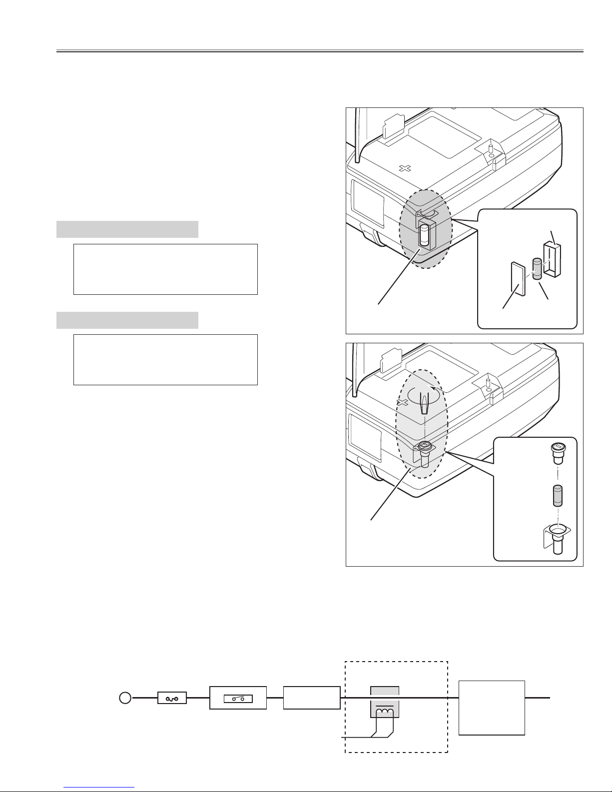
A fuse(F901) is located inside of the projector. When the
POWER indicator is not lighting, the fuse may be opened.
Check the fuse as following steps.
The fuse should be used with the following type;
● Fuse
How to replace the fuse
1. Remove the cabinet top following to "Mechanical
Disassemblies".
2. Remove the cover and the fuse from fuse holder.
To install the fuse, take reversed step in the above.
- 5 -
■ Circuit Protections
Fuse Part No.: 423 028 4209
TYPE 15.0A400V FUSE
SOC CORP. SHV14 15A N4
Fuse Part No.: 423 033 1804
TYPE 30.0A250V FUSE
SOC CORP. KST2 30A
PLC-XT4E
PLC-XT4U
Fuse (F901)
Fuse (F901)
Cover
Cover
Fuse
Fuse
Holder
Holder
● AC Current Sensor
AC current sensor is used only for LC-XT4E.
The AC Current Sensor is provided to prevent damage to the power supply circuits.
When AC input voltage is under 108V at MAINS SW ON, the AC Current Sensor will be operated and the CPU
does not turn the projector on, and both of READY and WARNING TEMP. indicators start flashing.
Check that the AC current sensor signal is correct. L : Abnormality
K96W
Hot circuit
AC-INPUT
FUSE
F901
MAINS SW
SW901
NOISE FILTER
LF901
CURRENT SENSOR
A903
ASS'Y POWER
Page 6
- 6 -
Circuit Protections
Lamp Cover switch
SW902
When the lamp cover is removed or no close completely, the lamp cover switch (SW902) cuts off
12V_PFC line to the PFC unit, and then a projector
will be shut down.
After opening the lamp cover for replacing the lamp
unit, place the lamp cover correctly, otherwise the projector can not be turned on.
Lamp Cover
● Lamp cover switch
● Power Failure Protection
Power failure protection diodes detect abnormal voltage on the power supply circuits or the fan operation stop.
When both of the WARNING TEMP. and READY Indicators are flashing:
When the projector detects an internal problem, it will shut down
automatically and both of the WARNING TEMP. and READY Indicators starts
flashing. In this condition, the projector cannot be turned on even if you press
the POWER ON-OFF button on the remote control unit or on the side control.
If this case happened, disconnect and reconnect the AC power cord, and
then turn on the projector again to check its operation. If the projector shuts
down again or fails to be turned on, the internal check and repair will be
required.
Check items listed below;
● Power Failure Protection
● AC Current Sensor (See the previous page.)
● Temperature Check of Lamps
● Lamp Cover Switch
READY
LAMP
LAMP
REPLACE
WARNING
TEMP.
FRONT INDICATORS
WARNING TEMP.
Indicator
READY
Indicator
WARN ING
TEMP.
READY
LAMP
REPLACE
LAMP
REAR INDICATORS
Temperature switches (SW 903~906)
are arranged near the four lamps.
Temperature switches will operate, if
temperature reaches 110 degrees.
Temperature switches
--- open at 110 degrees.
SW903 ---Lamp1
SW904 ---Lamp2
SW905 ---Lamp3
SW906 ---Lamp4
When temperature switches become
open, they cut off 12V_PFC line to
PFC(power factor control) unit, and
then a projector will be shut down.
● Temperature Check of Lamps
Temperature switch
SW906 (For Lamp4)
Temperature switch
SW905 (For Lamp3)
Temperature switch
SW903 (For Lamp1)
Temperature switch
SW904 (For Lamp2)
Page 7
- 7 -
Circuit Protections
READY
LAMP
LAMP
REPLACE
WARNING
TEMP.
When the WARNING TEMP. Indicator is flashing:
The WARNING TEMP. Indicator flashes red to let you know the internal
temperature of the projector exceeds the normal level. If the temperature goes
up further, the projector will be turned off automatically and the Ready indicator
will go out. (The WARNING TEMP. Indicator continues flashing.) After the
cooling-off period, the READY Indicator lights on again and the projector can be
turned on by pressing the POWER ON-OFF button on the remote control unit or
on the side control. When you turn on the projector, the WARNING TEMP.
Indicator will go out.
If the WARNING TEMP. Indicator is still flashing, check items listed below;
● Installation
● Air Filter
● Temperature Monitor System
FRONT INDICATORS
WARNING TEMP.
Indicator
WARNING
TEMP.
READY
LAMP
REPLACE
LAMP
REAR INDICATORS
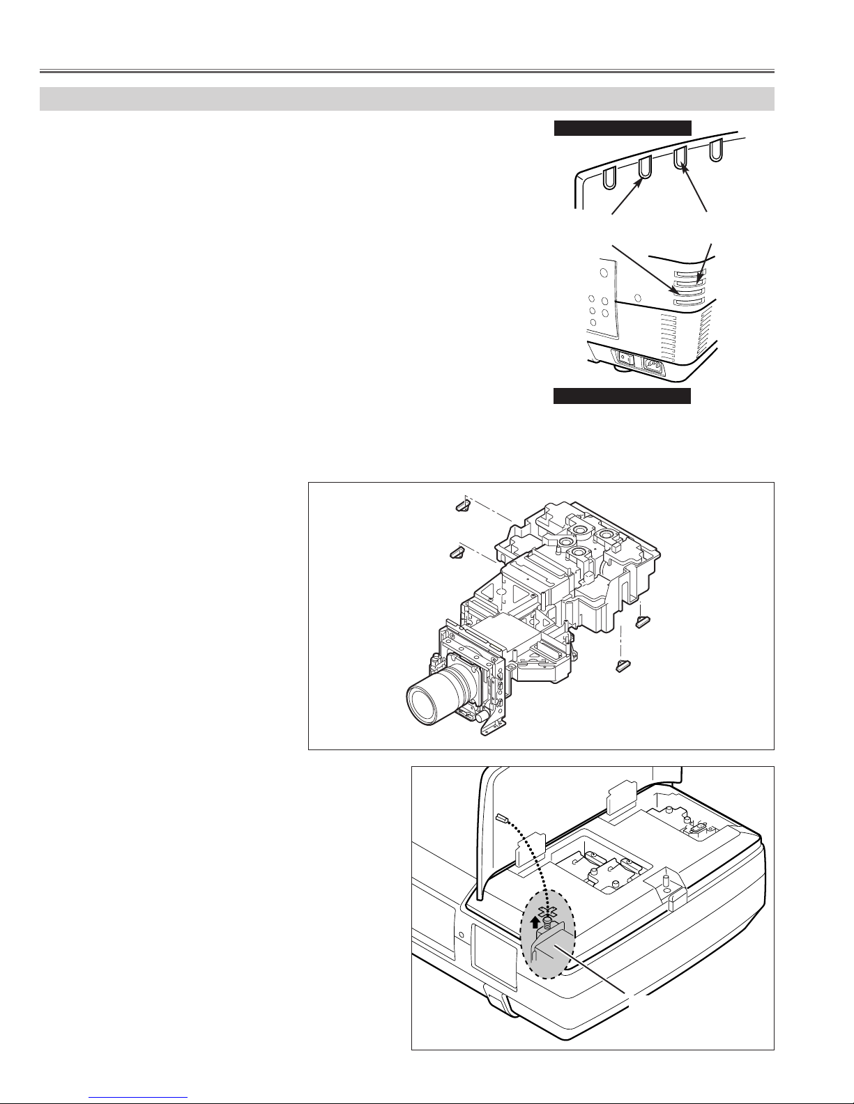
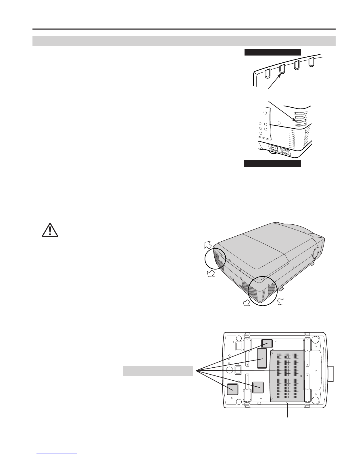
This projector is equipped with cooling fans for protection
from overheating. Pay attention to following to ensure proper ventilation and avoid a possible risk of fire and malfunction.
- Do not cover vent slots.
- Keep bottom clear any objects. Obstructions may block cooling air.
AIR INTAKE VENTS
EXHAUST VENTS
HOT AIR EXHAUSTED !
Air blown from exhaust vent is hot. When using
or installing a projector, following precautions
should be taken.
● Do not put flammable objects near these vents.
● Keep rear grills at least 3’ (1m) away from any object,
especially heat-sensitive object.
● Do not touch this area, especially screws and metallic
parts. This area will become hot while a projector is used.
HOT
● Installation
● Air Filter
- Air filter is clogged with dust particles. Remove dust from the air filter by following instruction in the "Air filter care
and cleaning".
- Ventilation slots of the projector are blocked. In such case, reposition the projector so that ventilation slots are not
obstructed.
- Check if projector is used at higher temperature place(Normal operate is 5 to 35°C or 41 to 95°F)
AIR FILTER
Page 8
- 8 -
Circuit Protections
■ To control the driving power of the cooling fans.
This projector detects internal temperature and automatically controls operating power of cooling fans.
The CPU checks the temperature and atmospheric pressure inside a projector. It checks a temperature using
temperature sensor-IC5801and it checks an atmospheric pressure using pressure sensor-IC886.
The CPU controls the driving power of the cooling fans so the temperature inside the projector is maintained to
normal temperature.
■ To shut down the projector.
The CPU checks temperature of Blue polarized glass (PTH901) and inhalation air(IC5801). If each part temperature reaches to abnormal temperature, the CPU will turn off a projector, and will blink WARNING TEMP. indicator at intervals of 0.5 seconds. Cooling fans operate until temperature returns to normal. WARNING TEMP.
indicator will stop blink, if temperature returns to normal.
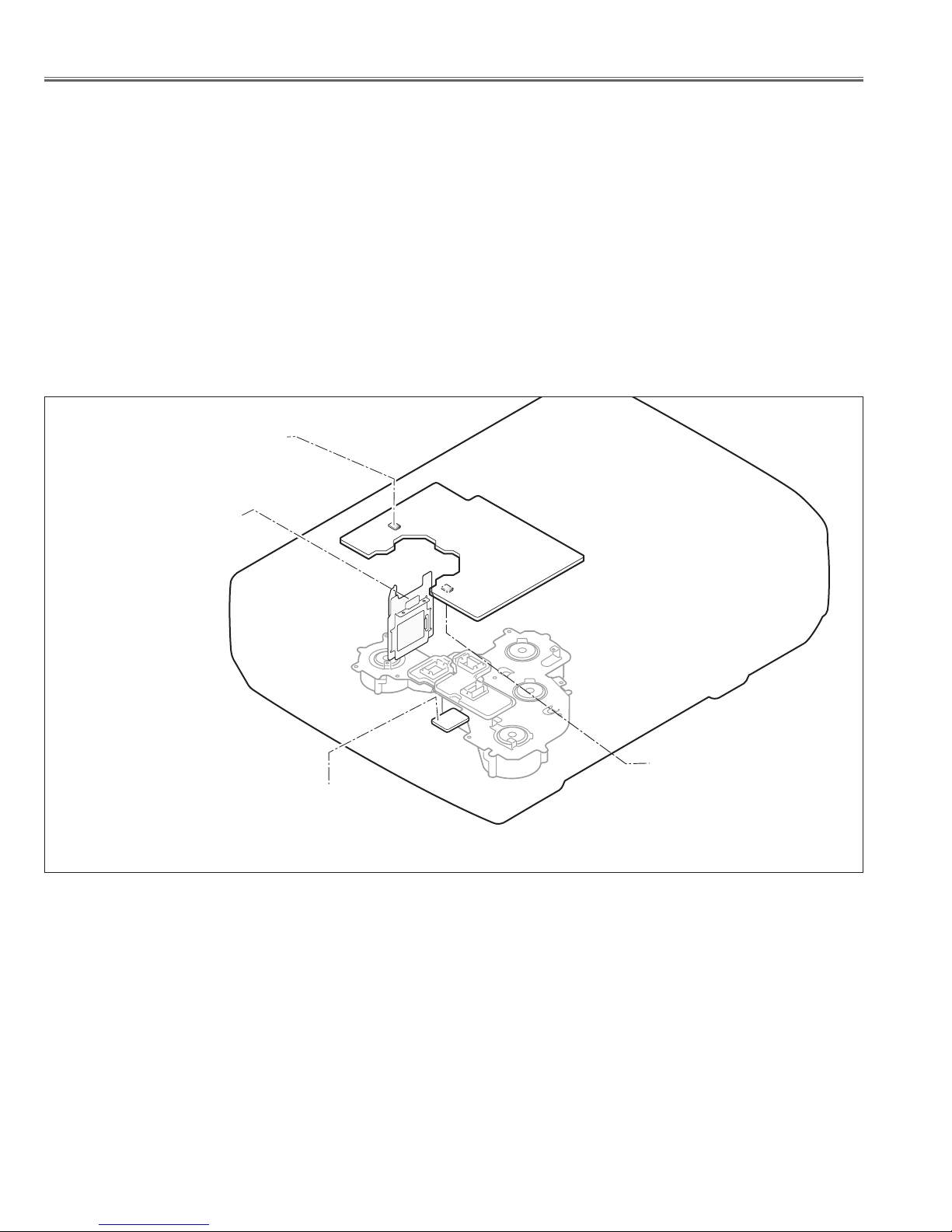
● Temperature Monitor System
Main Board
A-side
Front side
B-side
Temp. Sensor
IC2541
Temp. Sensor
(Inhalation air)
IC5801
Pressure Sensor
IC886
Temp. Sensor
(Blue polarized glass)
PTH901
Temperature sensors location
Blue polarizer unit
Page 9
- 9 -
■ Lamp Replacement
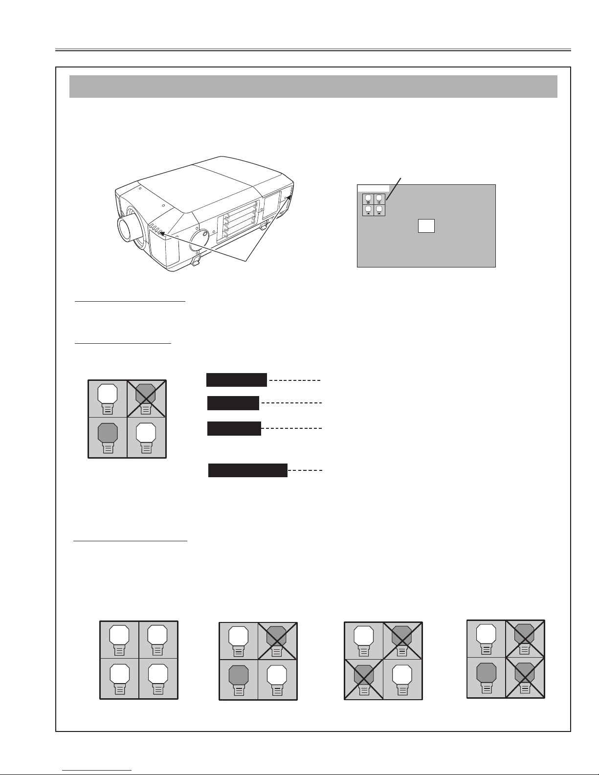
This Projector is equipped with 4 Projection Lamps to ensure brighter image and those lamps are controlled by Lamp
Management Function. Lamp Management Function detects status of all lamps and shows status on screen or on LAMP
REPLACE indicator. This function also automatically controls Lamp Mode when any of lamps is out for end of life or
malfunctions.
Projection Lamp lights normally.
Lamp Replace Indicator
This LAMP REPLACE indicator lights yellow when any of Projection Lamps is nearing its end, and flashes when any of them
becomes out. Check number of lamp on Lamp Status Display and replace lamp.
Yellow Lamp
Dim Lamp
X Mark on Lamp
Red Lamp
LAMP REPLACE
INDICATOR
Projection Lamp is turned off.
Projection Lamp is nearing its end. When image becomes
darker or color becomes unnatural, replace lamp. (LAMP
REPLACE indicator lights yellow.)
(LAMP REPLACE indicator flashes yellow.)
Projection lamp is defective or fails to be turned on. Restart
a projector on, and make sure lamp is on. If this mark still
appears, replace lamp corresponding with number marked
X.
LAMP STATUS
DISPLAY
1
4
3
2
Lamp Mode Changeover
Lamp Management Function automatically changes combination of lighting lamp (Lamp Mode) by detecting status of lamp.
When any of 4 lamps becomes out, Lamp Mode is changed over from 4 lamps to 2 lamps. And when any of 2 lamps are out,
a projector operates with 1 lamp. But, in case of combination that the Lamp of 1-4, or 2-3 does not light up, it becomes a 2
lamps mode.
Lamp Mode can be switched to 4 lamps or 2 lamps manually. Refer to SETTING section of Owner's manual
.
1
2 4
3
1
4
3
2
4 LAMP MODE
2 LAMP MODE
(Example)
1
4
3
2
2 LAMP MODE
(Example)
1
3
2
4
1 LAMP MODE
(Example)
Lamp Status Display
Lamp Status Display appears on screen when power switch is on or changed input position (input 1, input 2, Input 3 or input 4).
This shows status of each lamp as; ON, OFF, NEAR END, or OUT. Refer to following for each status.
20
LAMP STATUS
INPUT 1
1
2 4
3
LAMP MANAGEMENT (before replacement)
Page 10
- 10 -
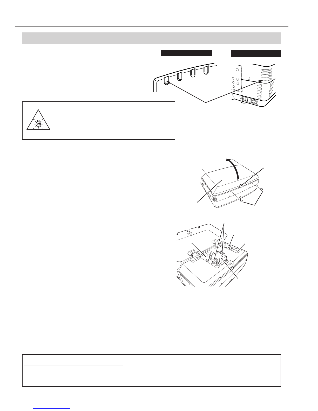
LAMP REPLACEMENT
Check number of lamp to be replaced on Lamp Status
Display.
Remove two screws on Lamp Cover and press button to
open Lamp Cover. (See right figure.)
1
3
Loosen two screws and pull out Lamp Assembly to be
replaced by grasping handle.
4
Turn off a projector and disconnect AC Power Cord.
Allow a projector to cool down for at least 45 minutes.
2
Replace Lamp Assembly with a new one and tighten two
screws. Make sure Lamp is set properly.
6
Follow these steps to replace lamp assembly.
Replace Lamp Cover and tighten two screws.
5
7
8
Connect AC Power Cord to a projector and turn a
projector on.
Reset Lamp Replacement Counter. (Refer to section
"Lamp Replace Counter".)
NOTE : Do not reset LAMP REPLACEMENT COUNTER when
lamp is not replaced.
BUTTON
SCREWS
SCREWS
LAMP1
LAMP2
LAMP
COVER
Make sure which number of lamp needs to
be replaced on Lamp Status Display.
Figure shows case of replacing LAMP 2.
CAUTION : Do not operate a Projector while any of lamps removed.
It may result in malfunctions, fire hazard, or other accidents.
NOTES ON LAMP REPLACEMENT
To maintain quality of picture (better balance of color and brightness in entire screen), we recommend replacing all 4 lamps at a time.
CAUTION : High pressure lamp may explode if improperly handled.
Refer to lamp replacement instructions.
When the life of the projection lamp of this projector
draws to an end, the LAMP REPLACE indicator
lights yellow. If this indicator lights yellow, replace
the lamp with a new one promptly.
The time when the LAMP REPLACE indicator lights
is depending on the lamp mode.
Lamp Replacement
LAMP3
LAMP4
WARNING :
TURN OFF THE UV LAMP BEFORE OPENING
THE LAMP COVER. USE UV RADIATION EYE
AND SKIN PROTECTION DURING SERVICING.
REAR INDICATORS
READY
LAMP
LAMP
REPLACE
WARNING
TEMP.
WARNING
TEMP.
READY
LAMP
REPLACE
LAMP
FRONT INDICATORS
LAMP REPLACE
INDICATOR
Page 11
- 11 -
CAUTION
Do not drop a lamp assembly or touch a glass
bulb! Glass can shatter and may cause injury.
CAUTION
For continued safety, replace with a lamp
assembly of same type.
Allow a projector to cool for at least 45 minutes
before you open Lamp Cover. Inside of a
projector can become very hot.
ORDER REPLA
CEMENT LAMP
Replacement Lamp can be ordered through your dealer. When ordering a Projection Lamp, give the
following information to the dealer.
● Model No. of your projector : LC-XT4U / LC-XT4E
● Replacement Lamp Type No. : POA-LMP100
(Service Parts No. 610 327 4928)
Lamp Replacement
Move pointer to Lamp counter reset and
then press SELECT button. Move
arrow to replaced lamp number (Lamp
1, Lamp 2, Lamp 3 or Lamp 4) and then
press
SELECT button.
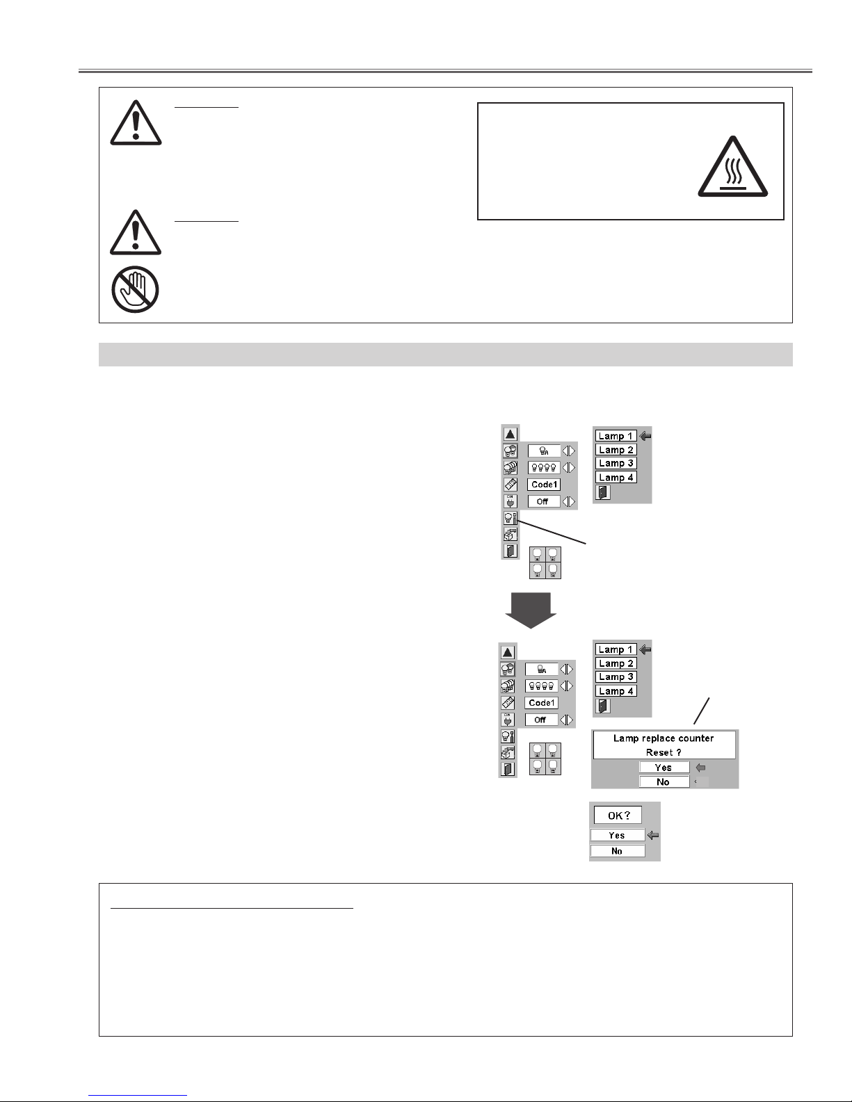
Be sure to reset Lamp Counter when Lamp Assembly is replaced. When Lamp Replace Counter is reset, LAMP
REPLACE indicator stops lighting.
Turn projector on, press MENU button and ON-SCREEN
MENU will appear. Press POINT LEFT/RIGHT button(s) to
move a red frame pointer to SETTING Menu icon.
1
Press POINT DOWN button to move a red frame pointer to
“Lamp counter reset” and then press
SELECT button.
2
Do not reset Lamp Replace Counter except after Projection lamp is
replaced.
Another confirmation dialog box appears and select [Yes] to
reset Lamp Replace Counter.
4
Move arrow to replaced lamp number (Lamp 1, Lamp 2, Lamp 3
or Lamp 4) and then press
SELECT button. Message "Lamp
replace counter Reset?" is displayed. Move pointer to [Yes] and
then press SELECT button.
3
NOTE: Be sure to reset correct lamp number otherwise LAMP
REPLACE indicator continues lighting.
Message "Lamp replace
counter Reset?" is
displayed. Move pointer
to [Yes] and then press
SELECT button.
Select [Yes] to
activate it.
LAMP REPLACE COUNTER
CAUTION
HIGH VOLTAGE
HOT
1
2 4
1
2 4
3
3
Page 12
- 12 -
This projector uses a high-pressure lamp which must be handled carefully and properly. Improper handling
may result in accidents, injury, or create a fire hazard.
● Lamp lifetime may differ from lamp to lamp and according to the environment of use. There is no
guarantee of the same lifetime for each lamp. Some lamps may fail or terminate their lifetime in a shorter
period of time than other similar lamps.
● If the projector indicates that the lamp should be replaced, i.e., if the LAMP REPLACE INDICATOR lights
up, replace the lamp with a new one IMMEDIATELY after the projector has cooled down.
( Follow carefully the instructions in the LAMP REPLACEMENT section of owner's manual. ) Continuous
use of the lamp with the LAMP REPLACE INDICATOR lighted may increase the risk of lamp explosion.
● A Lamp may explode as a result of vibration, shock or degradation as a result of hours of use as its
lifetime draws to an end. Risk of explosion may differ according to the environment or conditions in which
the projector and lamp are being used.
IF A LAMP EXPLODES, THE FOLLOWING SAFETY PRECAUTIONS SHOULD BE TAKEN.
If a lamp explodes, disconnect the projector’s AC plug from the AC outlet immediately. Contact an
authorized service station for a checkup of the unit and replacement of the lamp. Additionally, check
carefully to ensure that there are no broken shards or pieces of glass around the projector or coming out
from the cooling air circulation holes. Any broken shards found should be cleaned up carefully. No one
should check the inside of the projector except those who are authorized trained technicians and who are
familiar with projector service. Inappropriate attempts to service the unit by anyone, especially those who
are not appropriately trained to do so, may result in an accident or injury caused by pieces of broken glass.
LAMP HANDLING PRECAUTIONS
The LAMP REPLACE indicator will light yellow when
the total lamp used time (corresponding value) reaches
2,500 hours
- (✽). This is to indicate that lamp replacement is required.
The total lamp used time is calculated by using the
below expression;
Total lamp used time =
Teco + Tnormal x 1.25 - (✽)
Teco : used time in the Eco mode
Tnormal : used time in the Normal and Auto mode
You can check the lamp replacement counter following
to below procedure.
1 Press and hold POWER ON-OFF button on the side
control of the projector or the remote control unit for
more than 20 seconds.
2 The projector used time and lamp used time will be
displayed on the screen briefly.
(✽) The specifications are subject to change without
notice.
Total lamp used time
(Corresponding value)
● How to check Lamp Used Time
Projector used time
Lamp Replacement
Counter
Projector
Lamp
Normal
Eco
Corresponding
150H
No.1 No.2 No.3 No.4
100H
50H
175H
100H
50H
175H
100H
50H
175H
100H
50H
175H
Value
Page 13
After long periods of use, dust and other particles will accumulate on the LCD panel, prism, mirror, polarized glass,
lens, etc., causing the picture to darken or color to blur. If this occurs, clean the inside of optical unit.
Remove dust and other particles using air spray. If dirt cannot be removed by air spray, disassemble and clean the
optical unit.
● Cleaning with air spray
1. Remove the cabinet top following to "Mechanical Disassemblies".
2. Clean up the LCD panel and polarized glass by using the air spray from the cabinet top opening.
Caution:
Use a commercial (inert gas) air spray designed for cleaning camera and computer equipment. Use a resin-based nozzle only. Be vary careful not to damage optical parts with the nozzle tip. Never use any kind of cleanser on the unit. Also,
never use abrasive materials on the unit as this may cause irreparable damage.
● Disassembly Cleaning
Disassembly cleaning method should only be performed when the unit is considerable dirty and cannot be sufficiently
cleaned by air spraying alone.
Be sure to readjust the optical system after performing disassembly cleaning.
1. Remove the cabinet top and main units following to "Mechanical Disassemblies".
2. Remove the optical base top following to"Optical Unit Disassemblies". If the LCD panel needs cleaning, remove
the LCD panel unit following to "LCD panel/Prism ass'y replacement".
3. Clean the optical parts with a soft cloth. Clean extremely dirty areas using a cloth moistened with alcohol.
Caution:
The surface of the optical components consists of multiple dielectric layers with varying degrees of refraction.
Never use organic solvents (thinner, etc.) or any kind of cleanser on these components.
Since the LCD panel is equipped with an electronic circuit, never use any liquids (water, etc.) to clean the unit. Use of
liquid may cause the unit to malfunction.
- 13 -
■ Maintenance and Cleaning
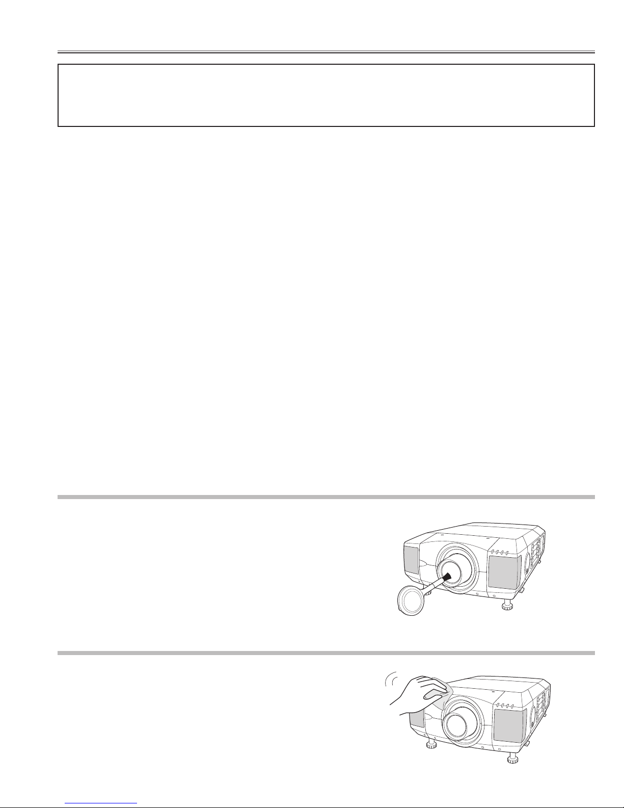
Unplug the AC power cord before cleaning.
Gently wipe the projection lens with a cleaning cloth that contains
a small amount of non-abrasive camera lens cleaner, or use a
lens cleaning paper or a commercially available air blower to
clean the lens. Avoid using an excessive amount of cleaner.
Abrasive cleaners, solvents, or other harsh chemicals might
scratch the surface of the lens.
Cleaning the Projection Lens
Cleaning the Projector Cabinet
Unplug the AC power cord before cleaning.
Gently wipe the projector body with a dry soft cloth. When the
cabinet is heavily soiled, apply a small amount of mild detergent
and finish with a dry soft cloth. Avoid using an excessive amount
of cleaner. Abrasive cleaners, solvents, or other harsh chemicals
might scratch the surface of the cabinet.
Page 14
- 14 -
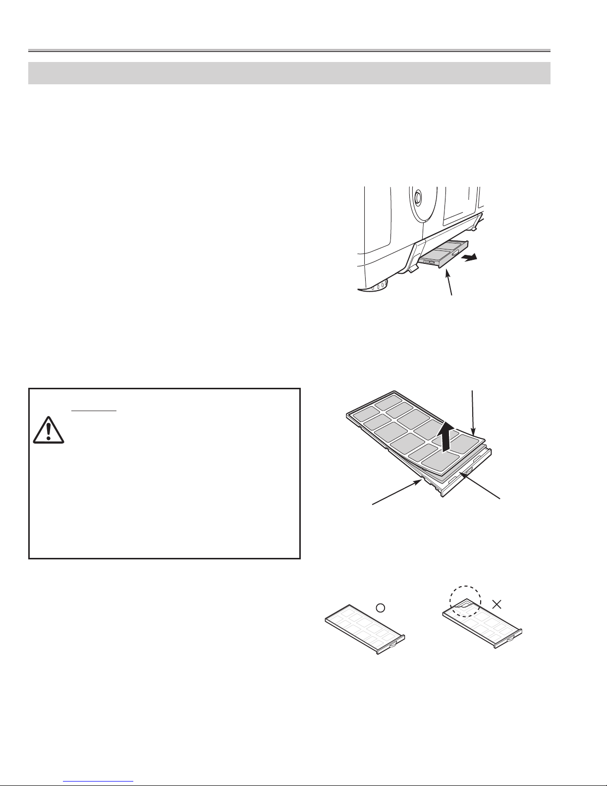
AIR FILTER CARE AND CLEANING
Air Filter prevents dust from accumulating on surface of Projection Lens and Projection Mirror. Should Air Filter
become clogged with dust particles, it will reduce Cooling Fans' effectiveness and may result in internal heat build up
and adversely affect life of a projector.
Clean Air Filter following steps below:
1
Turn power off, and disconnect AC power cord from AC
outlet.
2
Pull out air filter unit from the projector.
3
Pulling up center frame of air filter top, separate air filter
top and sheet from air filter base.
4
Clean each parts with brush, vacuum cleaner or wash
out dust and particles.
Be sure to dry them out.
5
Assemble sheet, air filter top and air filter base, and
replace air filter unit to a projector.
CAUTION
- Do not operate a projector with air filter removed.
Or dust may accumulate on LCD panel and
Mirror degrading picture quality.
- Do not put small parts into air Intake Vents. Or It
may result in malfunction of a projector.
- The filter be careful and handle. The effect of the
filter runs out in case of a leak and it being
broken off.
AIR FILTER UNIT
AIR FILTER TOP
AIR FILTER BASE
SHEET
Caution; Assembles sheet and filter base
Maintenance and Cleaning
Page 15

- 15 -
Before Disassemblies :
Turn off a projector and disconnect the AC power cord.
When remove the lens shift unit, shift to the position from which the attachment screws of a lens shift unit and an
optical base unit can be removed.
■ Mechanical Disassemblies
Disassemble should be made following procedures in numerical order.
Following steps show the basic procedures, therefore unnecessary step may be
ignored.
Caution:
The parts and screws should be placed exactly the same position as the original, oth-
erwise it may cause loss of performance and product safety.
The wiring method of the leads and ferrite cores should be returned exactly the same
state as the original, otherwise it may cause loss of performance and product safety.
Fig.1-1
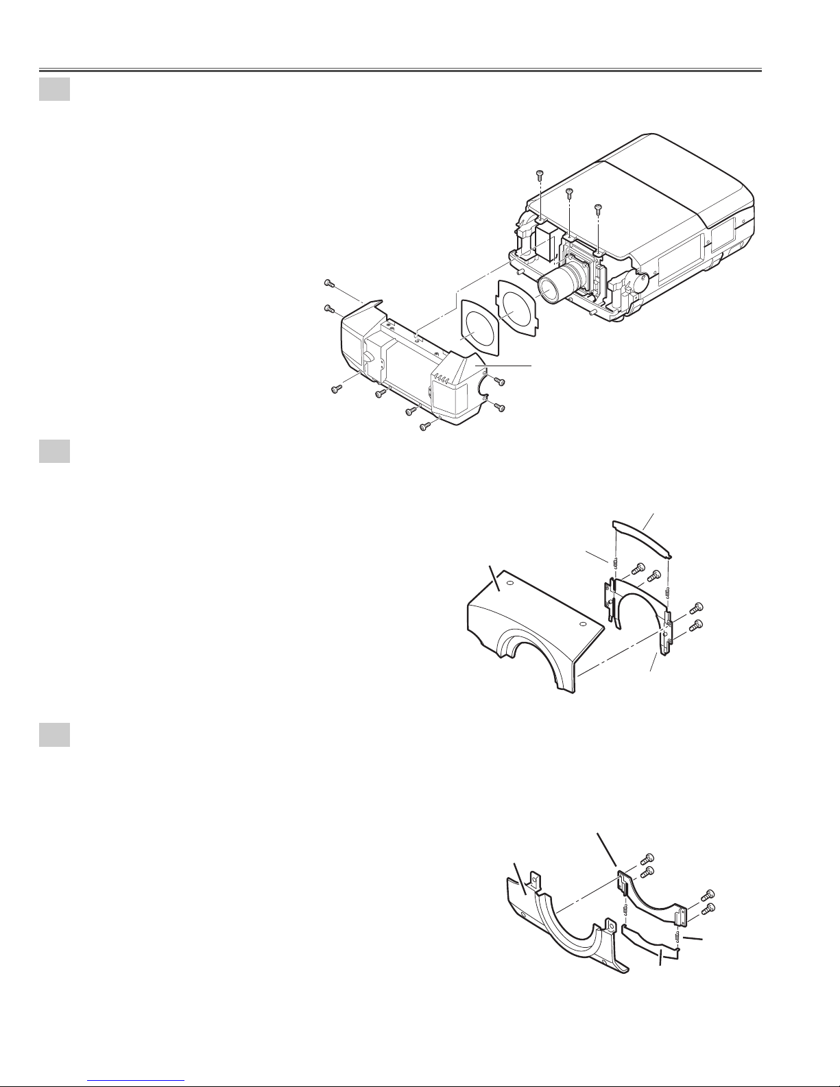
1-1
Cabinet front top unit and Cabinet front bottom unit removal.
Note :Be careful not to damage Hook. The cabinet front top unit is being fixed with cabinet front bottom by hook.
1. Remove 2 screws-A.
Push part(a) and pull the Cabinet front top unit upward.
2. Remove 4 screws-B and remove the Cabinet front bottom
unit.
(See Fig.1-1)
Refer to Lens replacement and installation manual.
Screw
Screw
Lens shift unit is moved to the position
from which an attachment screws can
be removed, as shown in a figure.
Lens shift unit
Screws Expression
(Type
Diameter x Length) mm
T type M Type
Ta pping screw Machine screw
A
Hook
(a)
B
B
B
B
Cabinet front top
unit
A
(a)
Cabinet front bottom unit
Page 16
- 16 -
Fig.1-3
Fig.1-4
1
-3
Cabinet front top unit disassemblies.
1. Remove 4 screws and remove the Mounting cover
lens-A.
2. Remove 2 Spring coils and remove Cover lens-A.
(See Fig.1-3)
1-4
Cabinet front bottom unit disassemblies.
1. Remove 4 screws and remove the Mounting cover lens-B.
2. Remove 2 Spring coils and remove Cover lens-A.
(See Fig.1-4)
Mechanical Disassemblies
Fig.1-2
1-2
Cabinet front unit removal.
1. Remove 11 screws and remove the Cabinet front unit.
(See Fig.1-2)
A
A
A
A
A
Cabinet front unit
A
A
A
A
A
A
Cover lens-A
Spring coil-A
Cabinet front top
Mounting cover lens-A
Mounting cover lens-B
Cabinet front bottom
Spring
coil-B
Cover lens-A
Page 17
- 17 -
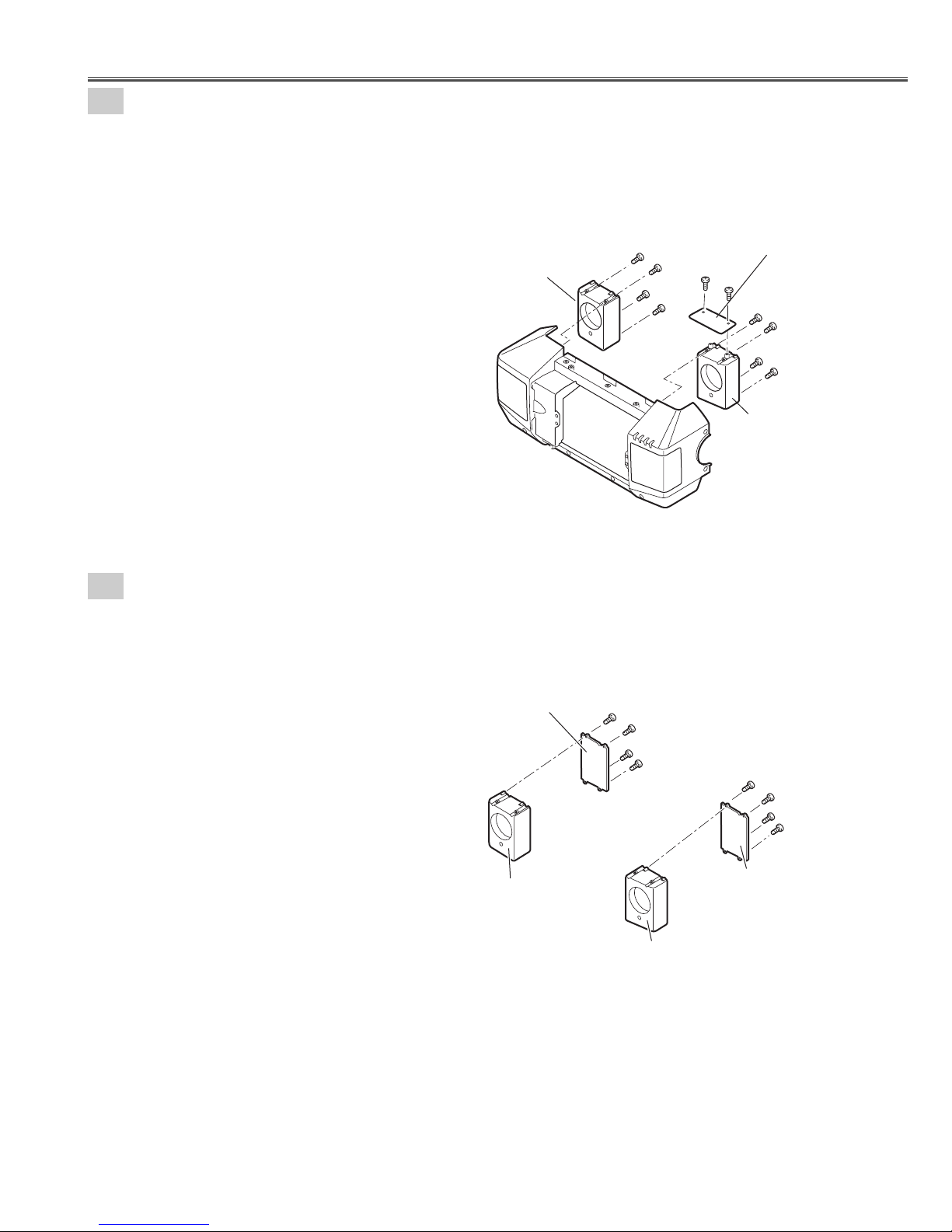
1
-6
Speaker units disassemblies.
1. Remove 4 screws-A and remove the Mounting SP-D.
2. Remove 4 screws-B and remove the Mounting SP-C.
(See Fig.1-6)
Fig.1-6
Mechanical Disassemblies
1-5
Speaker boxes and Front LED Board removal.
1. Remove 4 screws-A and remove the Speaker box-A.
2. Remove 4 screws-B and remove the Speaker box-B.
3. Remove 2 screws-C and remove the Front LED Board.
(See Fig.1-5)
Fig.1-5
Speaker box-A
Speaker box-B
Front LED Board
Cabinet Front
A
A
A
A
C
C
B
B
B
B
Mounting SP-D
Mounting SP-B
A
A
A
A
Mounting SP-A
B
B
B
B
Mounting SP-C
Page 18
- 18 -
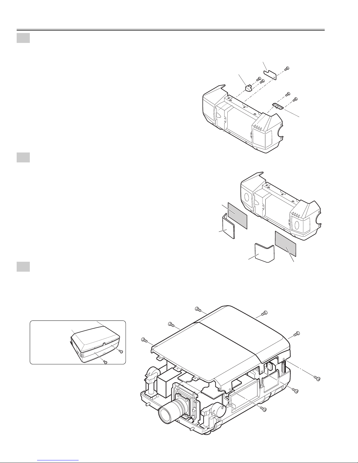
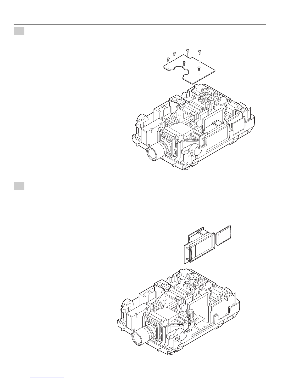
2-1
Cabinet-top unit removal.
1. Remove 8 screws and remove the Cabinet top unit.
(See Fig.2-1)
Fig.2-1
Fig.2-1a
Back View
Mechanical Disassemblies
1-7
Decoration Inlays and R/C-1 Board removal.
1. Remove screw-A and remove the R/C-1 Board.
2. Remove 2 screws-B and remove the DEC Inlay R/C-F.
3. Remove 2 screws-C and remove the DEC Inlay-A.
(See Fig.1-7)
1-8
Speaker Grills and Nets removal.
1. The bent portion is stretched and remove the Grille SP-L,
remove the Grille SP-R from cabinet front.
2. Remove the Nets.
(See Fig.1-8)
Mark the Grills as they are removed from the Cabinet front so that
they may be reassembled in the same location from which they
were removed. Be careful of the attached direction of Grills.
Fig.1-7
Fig.1-8
DEC Inlay R/C-F
Net
R/C 1 Board
B
B
A
C
C
DEC Inlay A
Cabinet front
Grill SP-L
Cabinet top unit
Grill SP-R
Net
Page 19
- 19 -
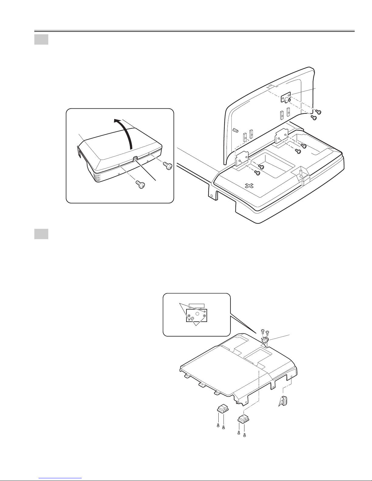
2-3
Decoration Inlay-B, Push Latch-A, and Hinges removal.
1. Remove 4 screws-A and remove the 2 Hinges.
2. Remove 2 screws-B and remove the push Latch-A.
3. Remove DEC Inlay-B. (Unhook the Cabinet top and take the DEC Inlay off inside.)
Push part(a) and pull the DEC Inlay inside.
(See Fig.2-3, 2-3a)
Fig.2-3
Fig.2-3a
Mechanical Disassemblies
2-2
Lamp cover and Push Latch-B removal.
1. Remove 2 screws-A and press button to open the Lamp cover.
2. Remove 4 screws-B and remove the Lamp cover.
3. Remove 2 screws-C and remove the Push Latch-B.
(See Fig.2-2, 2-2a)
Fig.2-2
Fig.2-2a
Cabinet top
Lamp cover
Push Latch-B
C
C
Lamp cover
A
Press
A
Button
Do not remove
B
B
B
B
Remove the screws
Cabinet top
Hinge
A
A
B
B
Push Latch-A
Hook
Hinge
A
A
DEC Inlay-B
(a)
Page 20
- 20 -
3
Main Board removal.
1. Remove 6 screws-A and remove the Main Board.
(See Fig.3)
4
-1
Control switch unit and Terminal slots unit removal.
1. Remove the Control switch unit upward.
2. Remove the Terminal slots unit upward.
(See Fig.4-1)
Fig.3
Fig.4-1
Mechanical Disassemblies
A
A
A
A
A
MAIN Borad
A
Terminal slots
Unit
Control Switch
Unit
Page 21
- 21 -
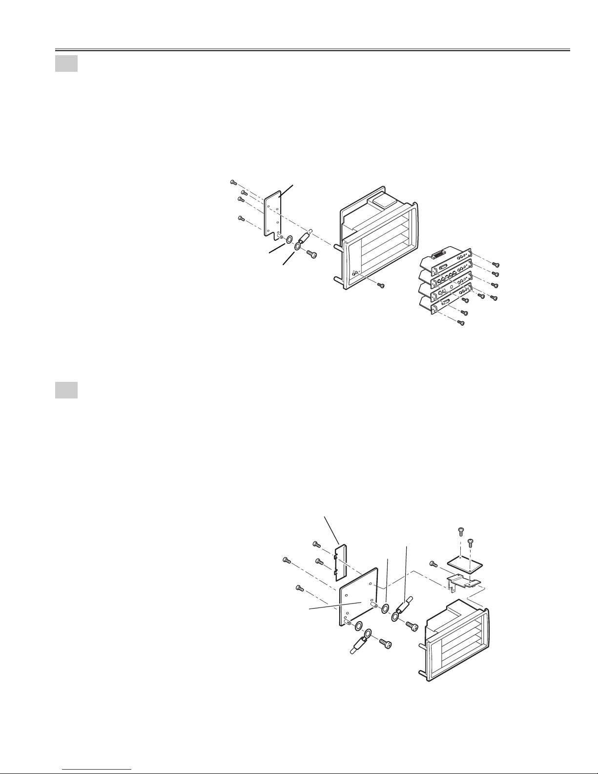
Fig.4-3
4
-3
Terminal Slot units disassemblies.
1. Remove 2 screws-A and remove the Lamp net Board.
2. Remove 2 screws-B and remove the Holder-B.
3. Remove 3 screws-C, remove the Holder-A and remove the CG Mother Board.
4. Remove 2 screws-D, remove 2 washers and remove Grounding Lead from the CG Mother Board.
(See Fig.4-3)
Mechanical Disassemblies
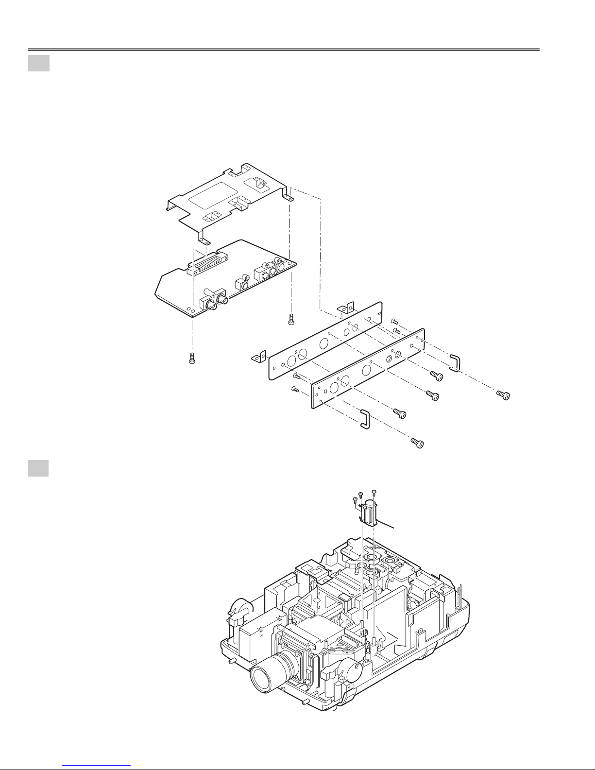
4-2
Terminal Board units and RS232C Board removal.
Fig.4-2
1. Remove 8 screws-A and remove the Terminal Board units 1-4.
2. Remove screw-B.
3. Remove 4 screws-C and remove the RS232C Board.
4. Remove screw-D, remove washer and remove Grounding Lead from the RS232C Board.
(See Fig.4-2)
Washer
Grounding
lead
RS232C Board
C
C
C
C
D
B
Terminal Board
units 1-4
A
A
A
A
A
A
A
A
C
C
CG Mother Board
Holder-B
B
B
Washer
Grounding Lead
Grounding Lead
Washer
D
D
A
A
C
Lamp net Board
Holder-A
Panel
Page 22
- 22 -
Mechanical Disassemblies
4-4
Control Switch unit disassemblies.
1. Remove 4 screws, remove the Control Button and remove the Control Board.
(See Fig.4-4)
Fig.4-4
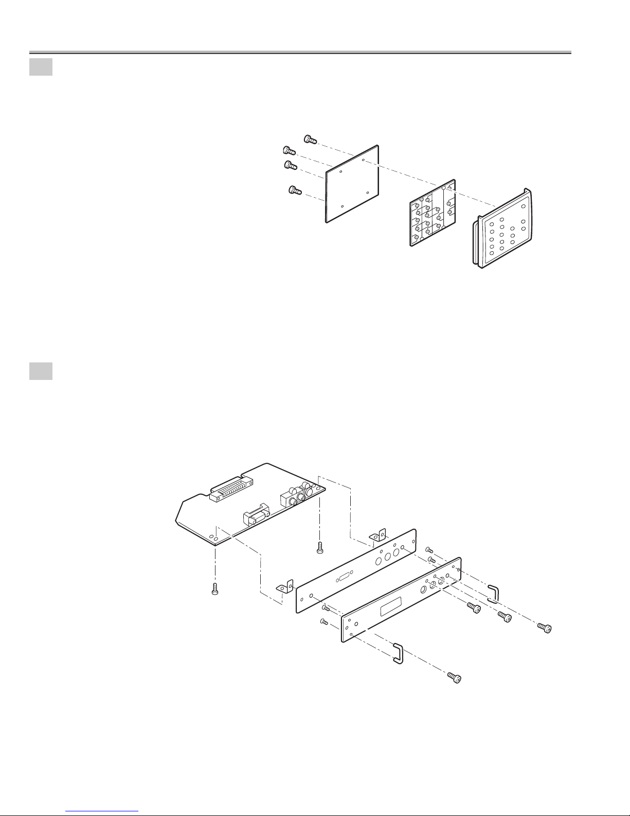
4-5
Terminal Board DVI disassemblies.
1. Remove 2 screws-A, remove screw-B, remove screw-C, and remove the Terminal Board DVI.
2. Remove 2 screws-D, remove the Holders and remove the Earth BRKT Slot.
3. Remove 4 screws-F and remove the Handles.
(See Fig.4-5)
Fig.4-5
Control Button
Control Board
Control Panel
A
Terminal board DVI
Holder
Earth BRKT Slot
A
F
F
Panel
Holder
F
F
Handle
B
C
D
Handle
D
Page 23
- 23 -
4
-7
1. Remove 2 screws-A ,remove screw-B, remove screw-C and remove the Terminal Board D-SUB15.
2. Remove 2 screws-D, remove the Holders and remove the Earth BRKT Slot.
3. Remove 4 screws-F and remove the Handles.
(See Fig.4-7)
Mechanical Disassemblies
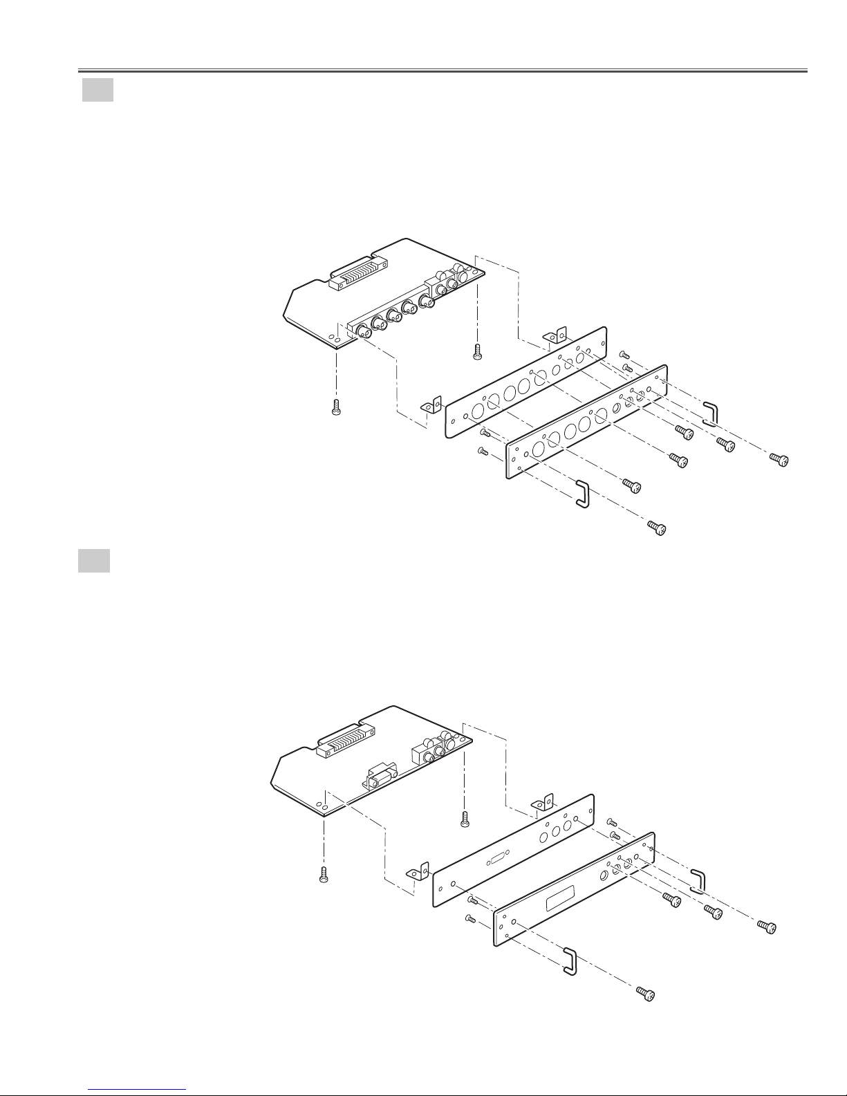
4-6
Terminal Board Component disassemblies.
1. Remove 2 screws-A ,remove 2 screws-B, remove screw-C,remove screw-D and remove the Terminal Board
Component.
2. Remove 2 screws-E, remove the Holders and remove the Earth BRKT Slot.
3. Remove 4 screws-G and remove the Handles.
(See Fig.4-6)
Fig.4-6
Fig.4-7
Terminal Board D-SUB15 disassemblies.
Terminal board Component
A
Holder
Holder
G
G
Handle
A
Earth BRKT Slot
Terminal board D-SUB
A
Holder
G
G
Panel
Holder
Handle
C
D
B
B
E
F
F
Handle
E
A
Earth BRKT Slot
F
F
Panel
B
C
D
Handle
D
Page 24
- 24 -
4-8
Terminal Board AV disassemblies.
1. Remove 2 screws-A, remove screw-B, remove screw-C,remove screw-D, remove the Heat sink and
remove the Terminal Board AV.
2. Remove 2 screws-E, remove the Holders and remove the Earth BRKT Slot.
3. Remove 4 screws-G and remove the Handles.
(See Fig.4-8)
Mechanical Disassemblies
Fig.4-8
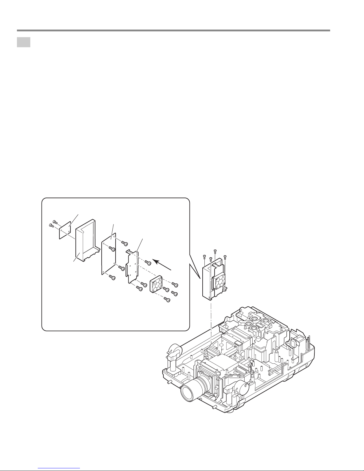
5-1
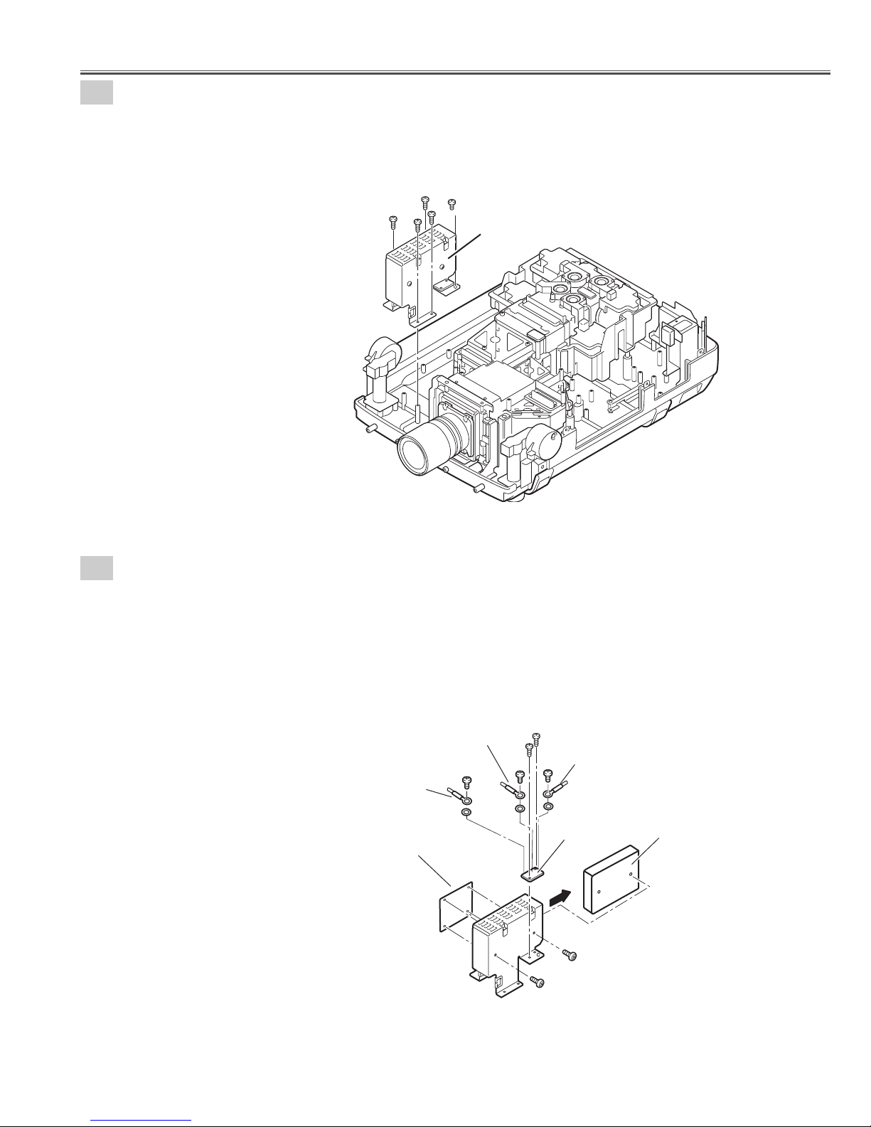
Fan(FN901) removal.
1. Remove 3 screws-A and remove the Fan(FN901).
(See Fig.5-1)
Fig.5-1
Heat sink
Holder
Terminal board AV
A
Earth BRKT Slot
Holder
A
G
G
Panel
Handle
A
A
A
G
G
B
Fan(FN901)
Handle
D
C
E
E
Page 25
- 25 -
5-2
Switch Power Supply(25V) unit removal.
Fig.5-2
1. Remove 4 screws-A, remove screw-B and remove the Switch power supply(25V) unit.
(See Fig.5-2 )
5-3
Switch Power Supply(25V) unit disassemblies.
1. Remove 2 screws-A and remove the Switch power supply(25V)Board.
2. Unhook the 4 Fixer Clamps and remove the Motor &Audio Board.
3. Remove 2 screws-B and remove the F-G net Board.
4. Remove 3 screws-C, remove 3 washers and remove the grounding lead.
(See Fig.5-3 )
Mechanical Disassemblies
Fig.5-3
A
B
A
A
A
SW-Power supply unit(25V)
Grounding
Lead
Washer
Motor and Audio
Board
Grounding
Lead
C
Washer
B
B
C
C
Grounding
Lead
Washer
F-G net Board
A
Switch Power Supply (25V)
Board
A
The Motor and Audio Board is fixed with
holder by hook.
Page 26
- 26 -
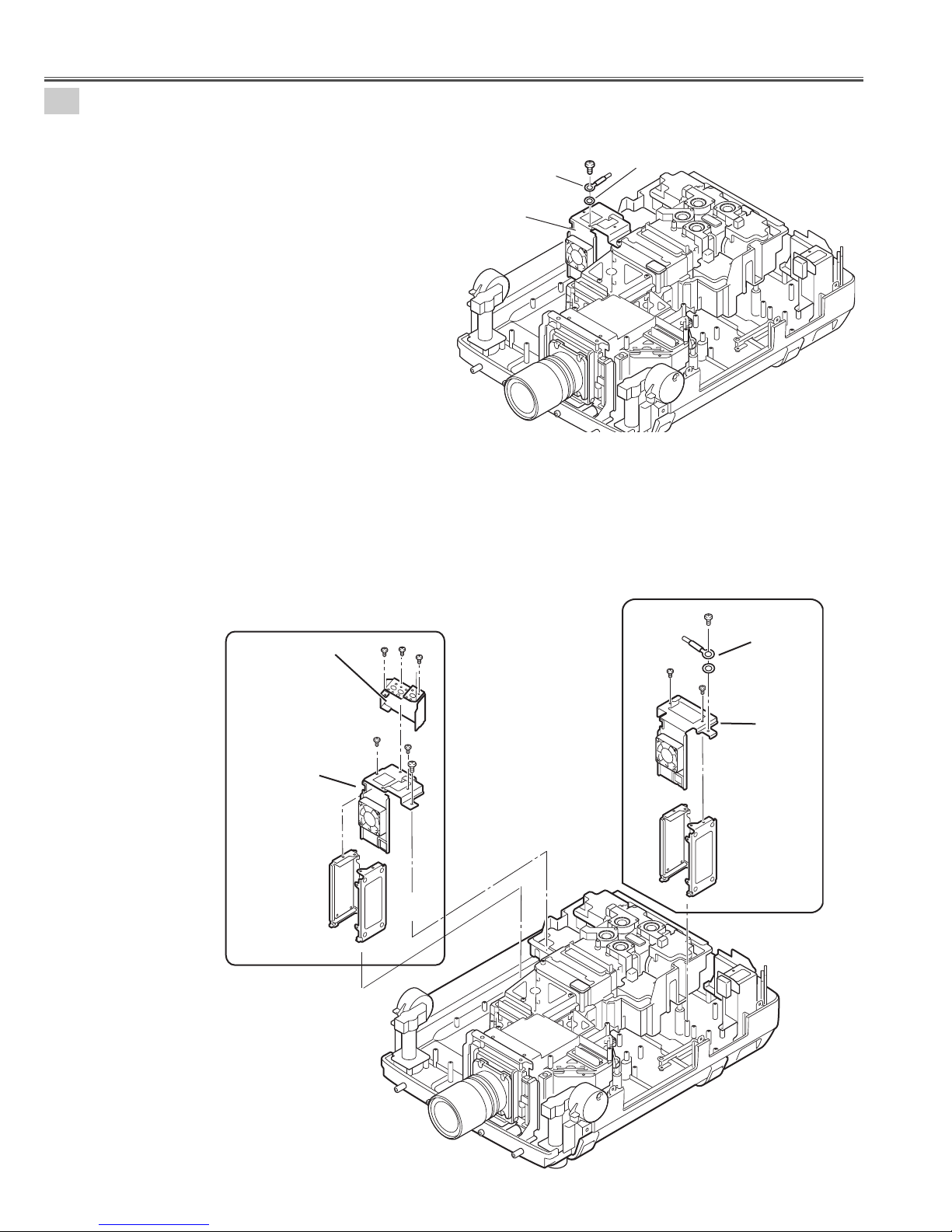
5-4
Lamp Ballast Units removal.
1. Remove screws-C, remove washer and remove the grounding lead. (Lamp ballast 3-4 units. See Fig.5-4)
Fig.5-4
Fig.5-4
Fig.5-4a
Fig.5-4b
Mechanical Disassemblies
2. Remove screw-A, remove washer and remove the grounding lead from the Holder.
(Lamp ballast 1-2 units. See Fig.5-4a)
3. Remove 2 screws-B and remove the Holder-D.
4. Remove the Lamp Ballast Unit1 and Lamp Ballast Unit2.
5. Remove 3 screws-F and remove the Holder-F.
6. Remove 2 screws-D, remove screw-E and remove the Holder-E.
7. Remove the Lamp Ballast Unit3 and Lamp Ballast Unit4.
(See Fig.5-4, 5-4a, 5-4b,)
Holder -F
C
Grounding
Lead
Lamp ballast
3-4 unit
Washer
A
F
F
F
B
Grounding Lead
Washer
B
Holder -E
Ballast4
Lamp ballast 3-4
units
D
D
E
Ballast3
Holder -D
Ballast2
Ballast1
Lamp ballast 1-2
units
Page 27
- 27 -
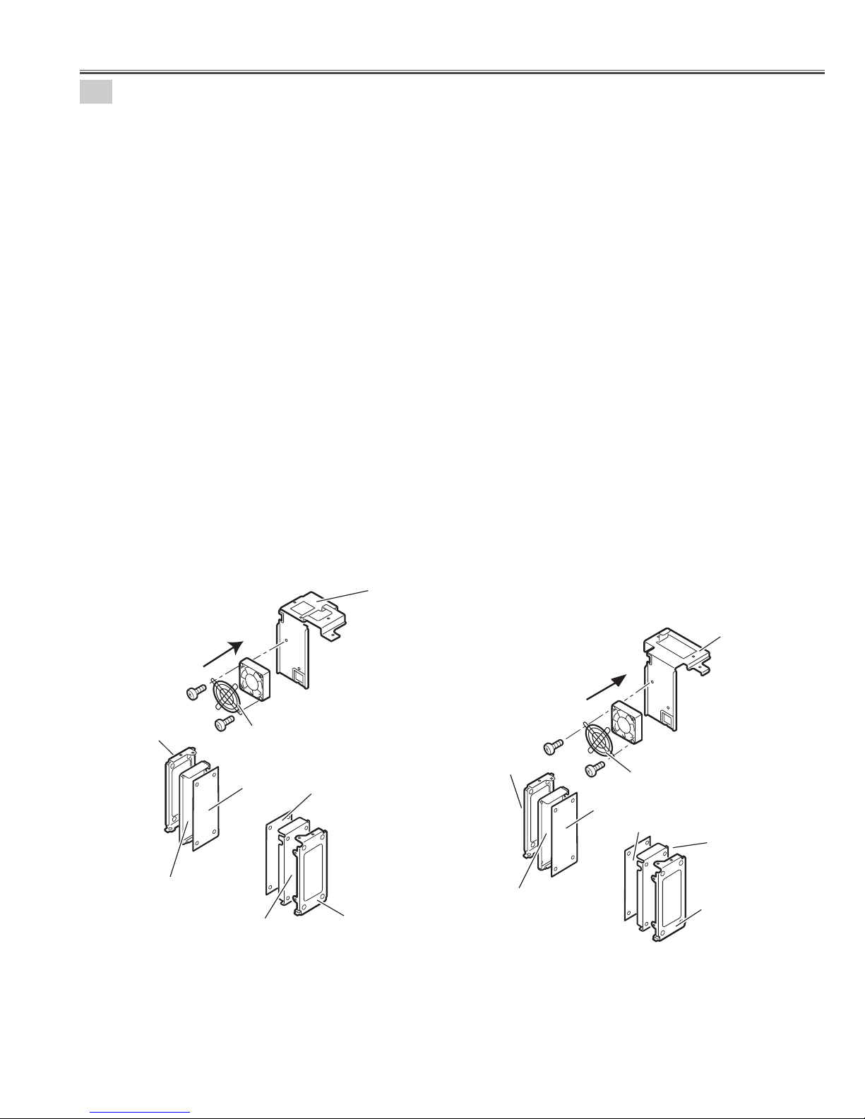
Note;
Mark the Fans as they are removed from the holder so that they may be reassembled in the same
location from which they were removed. Be careful of the attachment direction of Fans.
See arrow mark in a figure.
Ballast units may be reassembled in the same location and direction from which they were removed.
Be careful of the attached direction of Ballast units.
Lamp Ballast Units 1-2
1. Remove 2 screws-A, remove the Fan(FN908) and FAN Guard.
2. Remove Lamp Ballast unit 1 and remove the Spacer.
(Unhook the Fixer Clamp and remove the Lamp Ballast unit .)
3. Remove Lamp Ballast unit 2 and Spacer.
(Unhook the Fixer Clamp and remove the Lamp Ballast unit .)
(See Fig.5-5a)
Lamp Ballast Units 3-4
4. Remove 2 screws-B, remove the Fan(FN907) and FAN Guard.
5. Remove Lamp Ballast unit 3 and Spacer.
(Unhook the Fixer Clamp and remove the Lamp Ballast unit .)
6. Remove Lamp Ballast unit 4 and remove the Spacer.
(Unhook the Fixer Clamp and remove the Lamp Ballast unit .)
(See Fig.5-5b)
5-5
Lamp Ballast Units disassemblies.
Fig.5-5aFig.5-5b
Mechanical Disassemblies
Holder -C
Spacer
The direction
of a wind.
(FN907)
B
Ballast 4
FN907
FAN GUARD
B
Spacer
Ballast 3
Holder
Holder -E
A
Holder-C
Spacer
The Ballast Board is being fixed with
Holder by hook. (4places)
The direction
of a wind.
(FN908)
A
Ballast 2
Holder-D
FN908
FAN GUARD
Ballast 1
Spacer
Holder-C
Page 28
- 28 -
5-6
PFC Unit 3-4 and Power Unit removal.
PFC Unit 3-4 removal.
1. Remove 4 screws-A and remove the PFC 3-4 Unit.
2. Remove 4 screws-B and remove the Fan (FN914).
3. Remove 3 screws-C and remove the Holder FN.
4. Remove 4 screws-D and remove the PFC 3-4 Board.
5. Remove 2 screws-E and remove the AC net Board.
(See Fig.5-6, 5-6a)
Note;
Mark the Fans as they are removed from the holder so that they may be reassembled in the same location from
which they were removed. Be careful of the attached direction of Fan.
See arrow mark in a figure.
PWB board may be reassembled in the same location and direction from which they were removed. Be careful of
the attached direction of PWB board.
Fig.5-6
Fig.5-6a
Mechanical Disassemblies
E
E
AC net Board
Holder PFC
PFC3-4 Board
D
D
D
D
Holder FN
C
C
The direction
of a wind.
(FN914)
C
B
B
A
A
B
A
A
PFC3-4 unit
B
Page 29
- 29 -
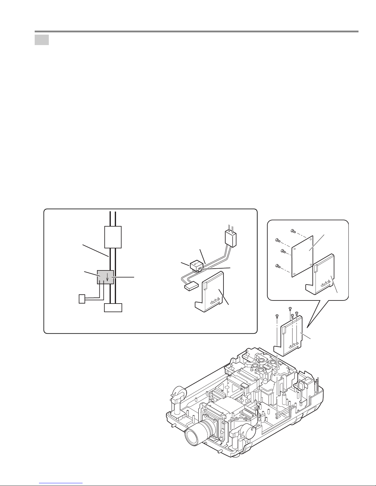
5-7
Current sensor removal and replacement.
(Current sensor is used only for PLV-HD2000E.)
Power unit
Ass'y Power unit
K6A
Current sensor
Current
sensor
K
L
K96W
Noise Filter
LF901
Blue lead wire
Blue lead wire
K6A
LF901
Printed mark
A903
(a)
1. Unhook the part(a) and remove the current sensor.
Note:The way of installing a current sensor is very important on the performance and the safety. Install in the
condition which is the same as the time of disassemble.
Replacement
1. The Current sensor is attached in the blue lead wire between a noise filter (LF901) and power unit (K6A).
2. The Current sensor (L) side is attached in the K6A side.
Refer to schematic diagrams.
PWB board may be reassembled in the same location and direction from which they were removed. Be careful of the
attached direction of PWB board.
(See Fig.5-7b)
Power Unit removal.
Power Unit removal.
1. Remove 2 screws-A, remove 2 screws-B and remove the Power Unit.
2. Remove 4 screws-C and remove the Power Board.
(See Fig.5-7, 5-7a)
Fig.5-7b
Fig.5-7a
Fig.5-7
Mechanical Disassemblies
Current sensor replacement
C
C
C
C
Power Board
Holder Power
A
B
B
A
Power unit
Page 30
- 30 -
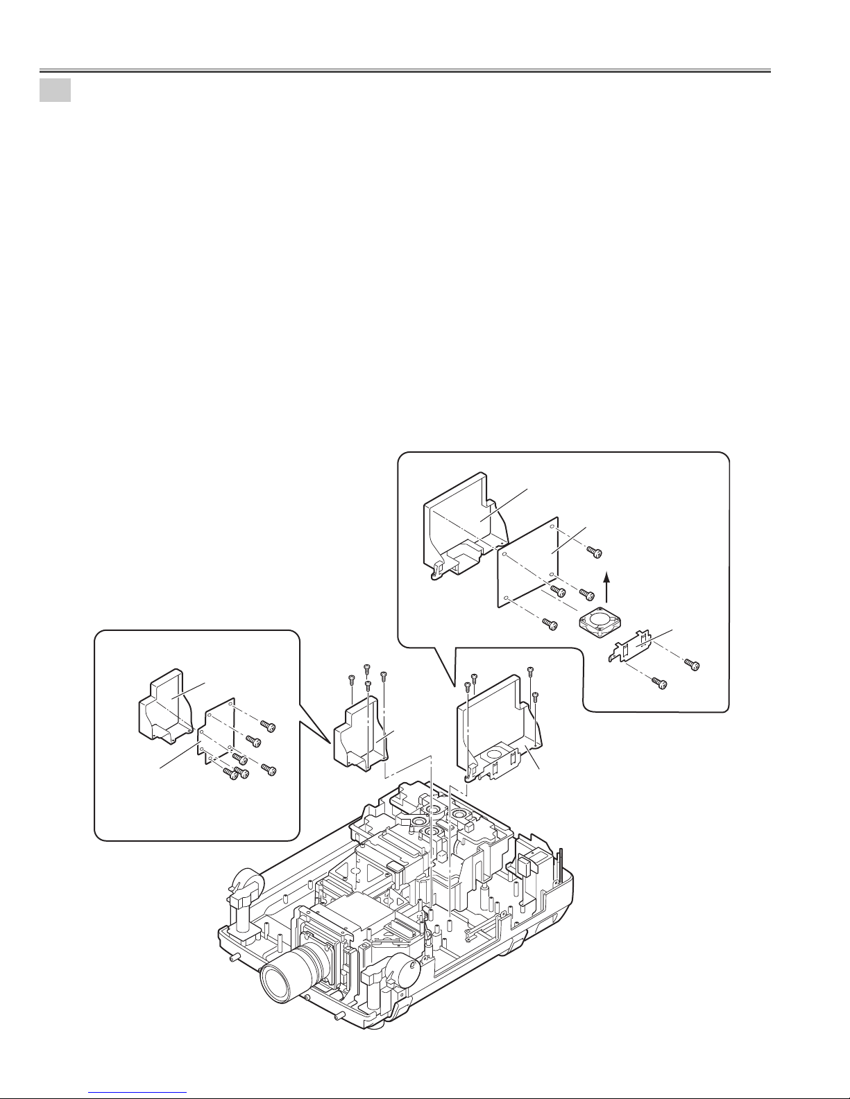
5-8
PFC 1-2 Unit and Sub Power Unit removal.
PFC 1-2 Unit removal.
1. Remove 4 screws-A and remove the PFC 1-2 Unit.
2. Remove 2 screws-B and remove the Holder FAN.
3. Remove the Fan (FN913).
4. Remove 4 screws-C and remove the PFC 1-2 Board.
(See Fig.5-8, 5-8a)
Sub Power Unit removal.
5. Remove 4 screws-D and remove the Sub Power Unit.
6. Remove 6 screws-E and remove the Sub Power Board.
(See Fig.5-8, 5-8b)
Note;
Mark the Fans as they are removed from the holder so that they may be reassembled in the same location from
which they were removed. Be careful of the attachment direction of Fan.
See arrow mark in a figure.
PWB boards may be reassembled in the same location and direction from which they were removed. Be careful of
the attached direction of PWB boards.
Fig.5-8
Fig.5-8a
Fig.5-8b
Mechanical Disassemblies
Sub Power Board
Holder Sub power
E
E
E
E
E
E
Holder PFC1-2
PFC 1-2 Board
C
The direction
C
C
D
D
D
D
Sub power
Unit
A
A
C
A
A
PFC1-2 Unit
of a wind.
(FN913)
Holder FAN
B
B
Page 31

- 31 -
6
Optical Unit removal.
1. Remove 10 screws-A, remove 4 screws-B and remove the Optical unit.
(See Fig.6)
Warning;
Do not hold the projection lens.
It may damage projection lens.
7
-1
Fan(FN906) Unit and Adjustable-feet removal.
1. Remove 6 screws-A and remove the Adjustable-foot-left.
2. Remove 6 screws-B and remove the Adjustable-foot-right.
3. Remove 2 screws-C and remove the Fan(FN906) Unit.
4. Remove 4 screws-D and remove the Fan(FN906).
5. Remove 3 screws-E and remove the Rear LED Board.
6. Remove screw-F and remove the PWB Holder.
(See Fig.7-1, 7-1a)
Note;
Mark the Fans as they are removed from the holder so that
they may be reassembled in the same location from which
they were removed. Be careful of the attached direction of
Fans.
See arrow mark in a figure.
Fig.6
Fig. 7-1
Fig. 7-1a
Mechanical Disassemblies
Warning!
Do not hold the Projection lens
B
B
B
B
B
B
A
Adjustable
foot-left
A
A
A
A
Adjustable
foot-right
A
A
A
A
A
A
B
B
B
B
A
A
A
A
A
Optical Unit
D
The direction
of a wind
FN906
C
C
C
C
Fan(FN906) unit
Holder FN
Rear LED Board
PWB Holder
F
D
D
D
E
E
E
Page 32

- 32 -
7-2
Fan Units removal and disassemblies.
Fan(R) Unit removal and Disassemblies.
1. Remove 3 screws-A and remove the Fan(R) Unit.
2. Remove 2 screws-B and remove the Duct-A.
3. Remove 2 screws-C and remove the Fan(FN903).
(See Fig. 7-2, 7-2a)
Fans(G,B) UNIT removal and Disassemblies.
4. Remove 4 screws-D and remove the Fan (G,B) Unit.
5. Remove 6 screws-F and remove the Duct-C.
6. Remove screw-G and remove the Sensor Board.
7. Remove 2 screws-H and remove the Fan (FN905).
8. Remove 2 screws-I and remove the Fan (FN916).
9. Remove 2 screws-J and remove the Fan (FN904).
10. Remove 2 screws-L and remove the RGB IN Fan net
Board.
(See Fig. 7-2, 7-2b)
Note :
Mark the Fans as they are removed from the duct so
that they may be reassembled in the same location
from which they were removed.
Fig 7-2
Fig.7-2b
Fig.7-2a
Mechanical Disassemblies
L
L
RGB IN Fan net Board
Duct-D
Duct-C
Duct-B
FN903
Duct-A
C
C
B
B
A
A
Fans (B,G) Unit
A
Fan (R) Unit
D
D
D
D
F
F
FF
Sensor Board
F
F
FN905
G
FN916
I
H
H
FN904
J
J
I
Page 33

- 33 -
Note : Removed grounding lead from the grounding mark may be reassembled in the same location.
8-1
Fans(FN909,FN910) and Holders removal.
1. Remove 2 screws-A and remove the Cover -E.
2. Remove 2 screws-B and remove the Fan(FN909).
3. Remove 3 screws-C and remove the Cover -F.
4. Remove 2 screws-D and remove the Fan(FN910).
5. Remove 4 screws-E and remove the Holder-A.
6. Remove 4 screws-F and remove the Holder-B.
7. Remove 4 screws-G and remove the Holder-C.
8. Remove 2 screws-H and remove the Holder-D.
(See Fig.8-1)
8-2
Grounding Leads removal.
1. Remove 2 screws-A, remove 2 washers and remove the grounding leads from the Holder.
(See Fig.8-2,8-2a)
Fig. 8-1
Mechanical Disassemblies
Fig. 8-2
Fig. 8-2a
Holder-C
G
A
A
Cover-E
Holder-B
G
G
G
F
F
F
B
F
FN909
Cover-F
C
B
C
D
FN910
C
D
E
Holder-A
E
E
H
E
H
A
Grounding
Lead
Washer
Grounding
Lead
Holder-D
A
Grounding
Lead
Washer
Grounding
Mark
Page 34

- 34 -
Fig. 8-3
Fig. 8-3a
8-3
Mains switch Unit removal.
1. Remove 4 screws-A and remove the Main-SW Unit.
2. Remove 2 screws-B and remove the Lamp Cover Switch(SW902).
3. Remove 2 screws-D and remove the AC Inlet.
4. Unhook the stoppers and remove the Mains Switch(SW901).
Push part(a) and pull the Main Switch.
5. Remove 2 screws-C and remove the Noise Filter.
(See Fig.8-3, 8-3a)
Mechanical Disassemblies
To remove the Fuse.
LC-XT4E
Turn the fuse holder cover with the slot screw driver.
Remove the fuse and the fuse holder cover upward.
LC-XT4U
Remove the fuse and the fuse holder cover forward.
Fuse holder
cover
Fuse
Fuse
Fuse holder
Fuse holder
cover
Fuse holder
Fig. 8-3b
Fig. 8-3c
MAIN-SW Unit
SW902
B
A
A
A
A
B
C
Noise Filter
LF901
Holder
C
AC Inlet
D
(a)
(a)
SW901
D
Hook
Page 35

- 35 -
9-1
Ducts, R/C 2 Board, Filter Unit, NET Board and Panel removal.
1. Remove 2 screws-A and remove the Duct D.
2. Remove 2 screws-B and remove the Duct C.
3. Remove screw-C and remove the R/C 2 Board.
4. Pull out Air Filter Unit.
5. Pulling up center frame of Filter top, separate Filter top and Sheet from Filter base.
6. Remove 3 screws-D and remove the Panel.
7. Remove 2 screws-E and remove the Lens NET Board.
(See Fig.9-1, 9-1a)
Fig. 9-1
Fig.9-1a
Mechanical Disassemblies
CAUTION
Do not operate a projector with air filter removed. Dust may accumulate on LCD panel and
Mirror degrading picture quality.
Do not put small parts into air Intake Vents. It may result in malfunction of a projector.
The filter be careful and handle. The effect of the filter runs out in case of a leak and it being
broken off.
Duct D
A
A
B
B
Duct C
Lens NET Board
E
E
R/C 2 Board
C
Filter Top
Air Filter Unit
Sheet
Filter Base
Panel
D
D
D
Page 36

- 36 -
1. Remove the Retaining ring(ER-type) by leaving it against the adjustable foot with slot screwdriver.
2. Turn the adjustable feet and to take from the Cabinet bottom off. (2 places)
3. Remove 20 screws and remove the Handles.
(See Fig.9-2, 9-2a)
9-2
Rear adjustable feet and Handles removal.
Mechanical Disassemblies
9-3
Shield plates and Sheets removal.
1. Remove the shield plates and sheets from the cabinet bottom.
(Shield plates are bent and attached in the cabinet bottom.)
(See Fig.9-3)
Fig.9-2
Fig.9-3
Fig.9-2a
Shield plates and Sheets
Slot screwdriver
Adjustable foot
(Rear)
Retaining
Ring
Adjustable feet
(2 Places)
Handle
Adjustable foot
(Rear)
Adjustable foot
(Rear)
Handle
Sheet-B
Shield Plate-B
Sheet-C
Shield Plate-C
Sheet-A
Shield Plate-A
Page 37

- 37 -
10-1
Net Boards(PBS Fan net, Lamp Fan net) removal.
1. Remove 2 screws-A and remove the PBS Fan net Board.
2. Remove 2 screws-B and remove the Lamp Fan net Board.
(See Fig.10-1)
10
-2
Fans(FN911, FN912), EXH Fan net Board and Duct removal.
1. Remove 3 screws-A and remove the Duct.
2. Remove 2 screws-B and remove the Fan(FN911).
3. Remove 2 screws-C and remove the Fan(FN912).
4. Remove 2 screws-D and remove the EXH Fan net Board.
(See Fig.10-2)
Mechanical Disassemblies
Fig. 10-1
Fig. 10-2
PBS Fan net
Board
B
A
A
B
Lamp Fan net
Board
FN912
C
C
EXH Fan net
Board
A
Duct
D
D
A
A
B
B
FN911
Page 38

- 38 -
Fig. 10-3
10-3
Fan(FN915), Ducts, and Temperature switches removal.
1. Remove 2 screws-A and remove the Fan(FN915).
2. Remove 2 screws-B and remove the Duct PBS.
3. Remove 4 screws-D and remove the temperature switches (SW903,SW904,SW905,SW906).
(See Fig.10-3)
Mechanical Disassemblies
Fig. 10-4
10
-4
Holders removal.
Note;
Mark the temperature switches as they are
removed from the optical base so that they
may be reassembled in the same location from
which they were removed.
1. Remove 2 screws-A, remove 3 screws-b and remove the Holder-A.
2. Remove 3 screws-C and remove the Holder-B.
(See Fig.10-4)
Temperature switch
SW906
Temperature switch
SW905
D
D
Temperature switch
SW903
D
B
Duct PBS
B
FN915
AA
Temperature switch
SW904
D
Holder-A
A
C
A
B
B
B
Holder-B
C
C
Page 39

- 39 -
■ Optical Unit Disassemblies
11
Projection lens and Lens shift unit removal.
1. Loosen the screw-D and remove the Safety Clamp. (See Fig. 11-a)
2. Slide the lens lock lever on the projector to "UNLOCK" (UPPER) position and detach
the Projection lens with Mount Parts to the Lens shift unit. (See Fig. 11-b)
(Refer to Lens replacement and Installation procedures manual)
3. Loosen 4 screws-A and remove the Projection lens.
4. Remove 4 screws-B and remove the Lens shift unit.
5. Remove 2 screws-C and remove the plate.
(See Fig.11, 11-c, 11-d)
Fig.11
Fig.11-d
Fig.11-c
B
B
B
B
Lens lock lever
Unlock(upper) position
Fig.11-b
Fig.11-a
Safety Clamp
Screw-D
C
C
Plate
Projection lens &
B
B
B
B
Lens shift unit
Attachment parts
A
Projection lens
Attachment parts
A
A
A
Page 40

- 40 -
t
12-2
LCD panels removal.
1. Remove 9 screws-A and remove the LCD panels.
Except when there is the necessity for replace, do not remove the LCD panel.
(See Fig.12-2,12-2a)
Note :
Do not remove all three LCD panels at the same time. The standard in convergence adjustment
runs out and it becomes not possible to do an adjustment. When exchanging three LCD panels at
the same time, it recommends to exchange every in the Prism/LCD panel unit.
Optical Unit Disassemblies
12-1
Prism/LCD panel unit removal.
1. Remove 4 screws and remove the Prism / LCD panel unit.
(Be careful not to damage the Prism / LCD panel unit with the driver.)
(See Fig.12-1)
Note :
Prism / LCD panel unit is a precision part. Be sure to
handle this part with special attention. Do not drop it
or give it excessive force. It may damage the parts
and alignment.
Caution :
(1). Do not touch the LCD panel and prism part
directly with hand. Otherwise the optical parts
may get dirty.
(2). Since the LCD panel is equipped with CMOS-
LSI, pay attention to static electricity. And do not
touch the electrode of flexible cables.
Fig.12-1
Fig.12-2
Fig.12-2a
Do not touch
the electrode of flexible cables.
Prism/LCD panel unit
A
A
A
A
A
A
A
A
A
LCDpanel
(Red)
LCDpanel
(Green)
LCDpanel
(Blue)
Prism/LCDpaneluni
Page 41

- 41 -
12-3
Optical filters and Polarized glasses disassemblies.
1. Remove 3 screws-A and remove the stoppers.
2. Remove the plate.
3. Remove the polarized glasses and Prepolarized glasses upward.
(See Fig.12-3)
Note:
Each polarized glasses use different characteristic polarization glasses. Mark the polarizer units as they
are removed from the optical unit so that they may be reassembled in the same location from which they
were removed.
Fig.12-3
Glass should be placed as the film attached side comes to the LCD panel side.
Optical Unit Disassemblies
A
Stopper
A
Stopper
Prepolarized glass
(out)
Prepolarized glass(out)
Polarized glass(out)
A
Stopper
Polarized glass(out)
Plate
Polarized glass(out)
(film side)
Prepolarized glass(out)
(film side)
Page 42

- 42 -
Integrator lens-in unit removal.
1. Remove 2 screws A and remove the Integrator lens in unit.
2. Remove 4 screws B and remove the 2 Plates.
3. Unhook the holder 4 places and remove the Integrator lens. (Integrator lens is bonded on the Holder.)
(See Fig.13-1, 13-1a)
13-1
Fig.13-1
Fig.13-1a
13
-2
Integrator lens-out / PBS unit removal.
1. Remove 3 screws-A and remove the Integrator lens out / PBS unit.
2. Remove 4 screws-B, remove the 2 Plates and remove the PBS.
3. Unhook the holder 4 places and remove the Integrator lens. (Integrator lens and PBS are bonded on the Holder.)
(See Fig.13-2, 13-2a)
Fig.13-2
Fig. 13-2a
Optical Unit Disassemblies
Plate
Slot part comes this top side
Unhook
Unhook
Unhook
Unhook
* Lens should be placed as the rugged surface
side comes to the Holder side.
Lens bonded on the Holder.
Holder
B
B
Plate
Integrator
lens-in
B
B
Rugged
surface
A
A
Integrator-lens-in
unit
A
A
A
Lens and PBS bonded on the holder.
Integrator-lens-out/
PBS unit
Plate
B
PBS
B
Slot part come this top side,
*Lens should be place
as the rugged surface
side comes to the Holder
side.
Integrator-lens-out
Unhook
Unhook
Holder
Rugged surface
B
B
Film attached side comes to the this side.
Plate
Page 43

- 43 -
13-4
Relay lens unit removal.
1. Remove 2 screws-A and remove the Relay lens unit.
2. Remove 4 screws-B, remove the plate and remove the Relay lens.
(See Fig.13-4, 13-4a)
Fig.13-4
Fig.13-4a
13-3
Condenser lens unit removal.
1. Remove 2 screws-A and remove the Condenser lens unit.
2. Remove 4 screws-B, remove the plate and remove the Condenser lens.
(See Fig.13-3, 13-3a)
Fig.13-3
Fig.13-3a
Optical Unit Disassemblies
A
A
Flat surface
plane comes this side
Condenser-lens
unit
B
* Lens should be placed as the flat surface side
comes to the Holder side.
B
Plate
B
Holder
B
Condenser lens
A
A
Relay lens
unit
Spherical surface
comes this side.
B
B
B
The printed marker comes this side.
B
Plate
Holder
Relay lens
Spherical surface
Side View
Page 44

- 44 -
13-5
Polarized units removal.
1. Remove 6 screws-A and remove the Polarized glass units. (See Fig.13-5)
Blue Polarized unit
5. Remove screw-E remove the plate(D) and remove
the Prepolarized glass(IN).
6. Remove 2 screws-F, remove the plates(E) and
remove the Optical filter (HCP).
7. Remove 2 screws-G, remove the plates(F) and
remove the Polarized glass (IN).
8. Remove screw-H, and remove the Temperature
sensor (PTH901) unit.
(See Fig.13-5b)
Red and Green Polarized Units
2. Remove screw-B, remove the plate(A) and remove
the Prepolarized glass(IN).
3. Remove 2 screws-C, remove the plates(B) and
remove the Optical filter (HCP).
4. Remove 2 screws-D, remove the plates(C) and
remove the Polarized glass (IN).
(See Fig.13-5a)
Optical Unit Disassemblies
Fig.13-5
Fig.13-5a
Fig.13-5b
A
A
Red
A
Green
A
Blue
Temperature sensor
(PTH901)
A
A
Prepolarized
glass (IN)
Polarized
glass (IN)
Plate (C)
Plate (B)
C
C
D
Plate (B)
D
Plate (C)
Optical
filter(HCP)
Holder
B
Plate (A)
Plate (E)
F
Temp. sensor unit
(PTH901)
H
Polarized
glass (IN)
Plate (F)
G
F
Plate (E)
G
Plate (F)
Optical filter(HCP)
Prepolarized
glass (IN)
E
Plate (D)
Page 45

- 45 -
13-6
Mirrors removal.
14
Assembly Lamps removal.
Loosen 8 screws-A and remove the 4 Lamp assemblies upward.
(See Fig.14)
Note :The characteristics and ages of lamps are managed by
CPU. Mark the lamp assemblies as they are removed
from the optical unit so that they may be reassembled in
the same location from which they were removed.
Remove 5 stoppers and pull the 5 mirrors upward.
(See Fig.13-6)
Note : Do not touch the mirrors surface directly with hand.
Each mirror uses different characteristic optical filter glasses. Mark the mirrors as they are
removed from the optical unit so that they may be reassembled in the location and direction
from which they were removed.
Fig.14
Fig.13-6
Optical Unit Disassemblies
CAUTION :
Do not operate a Projector while any of lamps removed. It may
result in malfunctions, fire hazard, or other accidents.
Do not drop a lamp assembly or touch a glass bulb! Glass may
shatter and may cause injury.
Stopper-A
Dichroic Mirror(C)
Stopper-B
Mirror(R)
Stopper-B
Mirror(B-cold)
Stopper-B
Dichroic Mirror(Y)
Stopper-B
Mirror(B-cold)
Lamp-3
Lamp-4
A
A
A
A
A
A
A
Lamp-2
A
Lamp-1
Page 46

- 46 -
15
Optical base top removal.
1. Remove 11 screws and remove the Optical base top.
Be careful not to damage the optical parts.
(See Fig.15)
Note:
Be careful of the optical base top slowly and remove it. Otherwise optical parts follow together and become
cause to damage.
16
Cover mirror and Fans (FN917, FN918, FN919, FN920) removal.
1. Remove 4 screws-A and remove the Cover mirror.
2. Remove 8 screws-B , unhooks the plates and remove the Fans.
(See Fig.16,16a)
Note :
Mark the Fans as they are removed from the cover mirror so that they may be reassembled in the
same location from which they were removed.
Fig.15
Fig.16
Fig.16a
Optical Unit Disassemblies
Optical base top
B
B
BB
Fan(FN920)
Fan(FN917)
B
Plate-C
Hook
Fan(FN919)
B
B
B
Plate-A
Plate-B
Fan(FN918)
Cover mirror
A
A
A
A
Page 47

- 47 -
17-1
Mirror units removal and disassemblies.
1. Remove 4 screws-A and remove the Mirror units.
2. Remove 4 screws-B and remove the Stoppers(C).
3. Remove screw-C and remove the Stopper(E).
4. Remove screw-D and remove the Stopper(D).
5. Remove 2 screws-E and remove the Stoppers(B).
6. Remove 4 screws-F and remove the Stoppers(A).
(See Fig.17-1, 17-2a)
Mirror units are same as.
Note : Do not touch mirrors surface directly with hand.
Fig.17-1
Fig.17-1a
Optical Unit Disassemblies
A
A
Mirror units
A
A
Mirror units
Stopper (A)
Stopper (C)
F
B
F
Stopper (D)
D
F
F
Stopper (A)
B
B
Mirror
Stopper (B)
E
Stopper (E)
C
The printed marker comes Holder side.
Holder
Mirror
Stopper (B)
E
Stopper (C)
B
Page 48

- 48 -
17-2
Optical Filter units removal and disassemblies.
1. Remove 2 screws-A and remove the Optical filter unit1.
2. Remove screw-E, remove the plate and remove the Optical filter upward. (See Fig.17-2a)
3. Remove 2 screws-B and remove the Optical filter unit2.
4. Remove screw-F, remove the plate and remove the Optical filter upward. (See Fig.17-2b)
5. Remove 2 screws-C and remove the Optical filter unit3.
6. Remove screw-G, remove the plate and remove the Optical filter upward. (See Fig.17-2c)
7. Remove 2 screws-D and remove the Optical filter unit4.
8. Remove screw-H, remove the plate and remove the Optical filter upward. (See Fig.17-2d)
(See Fig.17-2, 17-2a, 17-2b, 17-2c, 17-2d)
Note : Do not touch optical filters surface directly with hand.
Each mirror uses different characteristic optical filter glasses. Mark the mirrors as they are removed from
the optical unit so that they may be reassembled in the location and direction from which they were
removed.
Fig.17-2
Fig.17-2a
Fig.17-2b
Fig.17-2d
Fig.17-2c
Optical Unit Disassemblies
Printed marker
comes this
surface side.
OPTICAL FILTER UNIT 3
Plate
Optical filter
Holder
F
H
D
D
C
C
OPTICAL FILTER UNIT 4
B
B
A
A
OPTICAL FILTER UNIT 2
Plate
Optical filter
Printed marker
comes this surface
side.
Holder
Optical filter
Printed marker
comes this
surface side.
Plate
Holder
OPTICAL FILTER UNIT 1
G
E
Plate
Optical filter
Printed marker
comes this surface
side.
Holder
Page 49

- 49 -
A
s
18
Optical Filters and Lenses removal.
1. Remove Optical filter(UV/IR), remove the Condenser lens(IN), remove the Condenser lens(OUT), remove the
Relay lens(IN), remove the Condenser lens(R-FIL), remove the Condenser lens(UV-FIL), and remove the
Condenser lens(G) upward.
(See Fig.18)
Note : Do not touch optical filters and lenses surface directly with hand.
Mark the mirrors as they are removed from the optical unit so that they may be reassembled in the location
and direction from which they were removed.
19
Optical base BTM disassemblies.
1. Remove 6 screws-A, remove the Optical Base BTM-A and the Optical Base BTM-B disassemblies.
(See Fig.19)
Fig.18
Fig.19
Optical Unit Disassemblies
Lens condenser (R-FIL)
Lens condenser (UV-FIL)
Lens Condenser (OUT)
Optical filter (UV/IR)
Lens condenser (G)
Lens condenser (IN)
Arrow mark come
this figure.
Lens relay (IN)
Lens relay (IN)
A
Optical base BTM-B
A
A
A
A
Optical base BTM-A
Page 50

- 50 -
■ Optical Parts Location and Direction
Fig.31
Note: There are 2 types of Optical unit. (Type-R and Type-L)
Each Optical unit must combine and use the specific Optical parts.
TYPE-R TYPE-L
R
Marking (R or L)
Confirm the label of a LCD
panel/prism assembly and the
optical unit. (R or L)
R
114
A
128R
128L
105
107
114
107
120
127R
127L
104
121
A
121
130R
130L
122
102
125
B
118
129R
129L
106
117
119
L
107
115
A
118
103
B
112
Lamp1
Lamp2
101
126
123
116
116
A
110
A
111
A
Lamp3
A
Lamp4
A
110
A
A
A
111
A
Page 51

- 51 -
101
PRISM ASSEMBLY (PBS)
102 DICHROIC MIRROR (Y)
103 DICHROIC MIRROR (C)
104 POLARIZED GLASS (IN/B)
105 POLARIZED GLASS (IN/G)
106 POLARIZED GLASS (IN/R)
107 PREPOLARIZED GLASS (IN)
110
OPTICAL FILTER
111 OPTICAL FILTER
112 OPTICAL FILTER (UV/IR)
114 MIRROR (B-COLD)
115 MIRROR (R)
116 MIRROR (COLD)
117 LENS-CONDENSER(R-FIL)
119 LENS-CONDENSER (IN)
120 LENS-RELAY (OUT)
121 LENS-RELAY (IN)
122 LENS-CONDENSER(G)
123 LENS-INTEGRATOR
125 LENS-CONDENSER(UV-FIL)
126 LENS-INTEGRATOR(OUT)
127R OPTICAL FILTER (HCP)(TYPE-R)
127L OPTICAL FILTER (HCP)(TYPE-L)
128R OPTICAL FILTER (HCP)(TYPE-R)
128L OPTICAL FILTER (HCP)(TYPE-L)
129R OPTICAL FILTER (HCP)(TYPE-R)
129L OPTICAL FILTER (HCP)(TYPE-L)
130R PRISM/LCD PANEL ASSEMBLY(TYPE-R)
118 LENS-CONDENSER(OUT) 130L PRISM/LCD PANEL ASSEMBLY(TYPE-L)
KEY No. DESCRIPTION KEY No. DESCRIPTION
130-1
130-1
130-2
130R-7
130R-6
130R-8
130-3
130-4
130-5
(RED)
(GREEN)
(BLUE)
NO.130R
LCD Panel/Prism ass'y (TYPE-R)
Optical Unit Type-R
130-1
130-2
130-3
130-4
130-5
POLARIZED GLASS(OUT)RB
POLARIZED GLASS(OUT)G
POLARIZED GLASS(OUT/R)
POLARIZED GLASS (OUT/G)
POLARIZED GLASS (OUT/B)
130-6R LCD PANEL (R) (TYPE-R)
130-7R LCD PANEL (G) (TYPE-R)
130-8R LCD PANEL (B) (TYPE-R)
130-1
130-2
130-3
130-4
130-5
POLARIZED GLASS(OUT)RB
POLARIZED GLASS(OUT)G
POLARIZED GLASS(OUT/R)
POLARIZED GLASS (OUT/G)
POLARIZED GLASS (OUT/B)
130-6L LCD PANEL (R) (TYPE-L)
130-7L LCD PANEL (G) (TYPE-L)
130-8L LCD PANEL (B) (TYPE-L)
Fig.32a
130-1
130-1
130-2
130L-7
130L-6
130L-8
130-3
130-4
130-5
(RED)
(GREEN)
(BLUE)
NO.130L
LCD Panel/Prism ass'y (TYPE-L)
Optical Unit Type-L
Fig.32b
Optical Parts Location and Direction
Page 52

- 52 -
Fig.33
Fig.34
Fig.35
Fig.36
Fig.37
Fig.38
Fig.39
Fig.40
Fig.41
Printed marker comes this
surface side.
Printed marker comes always to
the position of the figure.
Mirror and Optical filter
Dichroic mirror
Condenser Lens(OUT)
Condenser Lens(IN)
Plane surface comes
this side.
PBS and Integrator lens (OUT)
Integrator lens (In)
Slot part comes this top
side.
Slot part comes this
top side.
Integrator lens should be
placed as rugged surface side
comes to the Holder side.
Integrator lens should be
placed as rugged surface side
comes to the Holder side.
Printed marker comes
this position.
(The lower side of back)
Film attached side comes to
this side.
Polarized glass
LCD Panel
Film attached
side.
Polarized glasses should be placed
as the film attached side comes to
the LCD panel side.
Optical filter(HCP)
Optical filter(HCP) and Polarized glass
Prepolarized glass(IN)
Film attached side
Polarized glass(IN)
Film attached side
Marker comes
this top side.
Slit comes Polarized
glass side.
Rugged surface
side
Spherical surface side
The marker comes this surface side
(Non Spherical surface side)
Relay lens(OUT)
The arrow mark points at the
LCD panel.
LCD
panel
Optical Parts Location and Direction
A
B
B
Flat surface
Condenser lens(out)
Page 53

- 53 -
Check the CG_MOTHER Board.
Check the Vcc voltages.
S9V / S6V (Always)
9V / 5VB / -5V (Switched)
Check the signal lines.
● No Picture
■ Troubleshooting
SLOT1
DIF SCDT/H/V
DIF DE
BB
GB
RB
BA
GA
RA
DIF CLK1/2/3/4
IC9041
BUFFER
<74VCX2374>
IC9031
BUFFER
<74VCX16821>
IC9032
BUFFER
<74VCX16821>
IC9033
BUFFER
<74VCX16821>
IC9014
DIFCLK
SELECTOR
<QS3125>
DIF SCDT/H/V
DIF DE
IC9016
IC9017
DIF CLK
TO MAIN BOARD "K32A" TO MAIN BOARD "K32B" "K2R"
K90A K90B
SLOT2
SLOT3
SLOT4
K90FK90EK90DK90C
CS1/2/3/4
SLOT_SEL1/SEL2
SLOT1 R/G/B
SLOT2 R/G/B
SLOT_SEL1/SEL2
SLOT3 R/G/B
SLOT4 R/G/B
SLOT_SEL1/SEL2
SLOT1 AUDIO_L/R
SLOT2 AUDIO_L/R
SLOT3 AUDIO_L/R
SLOT4 AUDIO_L/R
M-IDA1/2/3/4
M-IDB1/2/3/4
M-IDC1/2/3/4
SLOT1/2/3/4_ID
IC9013
SLOT ON SW
<4052>
IC9001
SYNC SW
<4052>
IC9006
RGB SW
<AD8185>
IC9007
RGB SW
<AD8185>
IC9002
AUDIO SW
<4052>
IC9021
I/O EXPANDER
<M62320>
IC9022
I/O EXPANDER
<M62320>
SLOT1/2/3/4 ON
C_SYNC
HS / VSSLOT1/2/3/4 H/V
SLOT TYPE
DETECTOR
IC9005
BUFFER
R
G
B
R
G
B
AUDIO_L/R
IIC_SCL/SDA
SLOT TYPE
DETECTOR
SLOT ID
H/V_SYNC
K90K
K90L
K90M
TO MAIN BOARD
R
"K2G" "K2B" TO MAIN BOARD "K8A"
G
B
K90Q
Page 54

-54-
CHECK
RGB SIGNAL
CHECK
SYNC SIGNAL
● No Picture
Troubleshooting
FROM CGMOTHER BOARD "K90A"
K32A
FROM CGMOTHER BOARD "K90B"
K32B
C_SYNC
H_SYNC
V_SYNC
"K90K" "K90L" "K90M"
R
G
B
FROM CGMOTHER BOARD
ANALOG INPUT
H_DIF W_HS
V_DIF
DE_DIF
DIFCLK
BO_DVI
GO_DVI
RO_DVI
DIGITAL INPUT
BE_DVI
GE_DVI
RE_DVI
IC8251
BO
GO
RO
BE
GE
RE
BUFFER
IC8201
BUFFER
IC8211
BUFFER
IC8221
SW_DVI
IC8261
TP32V1
TP201
TP211
TP221
IC8261
IC8261
IC201
IC211
IC221
IC8261
TPHV
IC281
CLAMP
<LT1260>
IC8253
5
13
20
CLP_RGB, CLP_TIM
TPV
CNT_VS
IC8251
VS_INAD_HS
IC2201
A/D
<AD9888>
IC2261
FREQ.
COUNTER
<CXA2151>
IC8253
RA/RB/GA/GB/BA/BB
IC8251
W_VS
W_DE
W_CLK
BA/GA
RA/BB
GB/RB
CHS
CNT_HS
SW_CS
IC8251
COAST_AD
W_CLK
RA/RB/
GA/GB/
BA/BB_IN
CLKO/HO/
VO_I P
IC6314,16,17,18
<EM638325TS>
DATA/ADDRESS BUS
IC2301
SW_FPGA
PRE-SELECTOR
<XC2S200>
RA/RB/
GA/GB/
BA/BB_IP
IPSH
<ICS1523>
IC4201
CONVERTER
<TC240C4FTB>
SDRAM
GPEN/GCLK/GVS_PW
HSYNC
IC4231
VCO
R_HSCLK
I/P
GRO/GRE/
EEPROM
GGO/GGE/
GBO/GBE_PW
BUFFER
IC4261
BUFFER
IC4271
BUFFER
IC4281
SCL/SDA_PW2
IC1311
SCL/SDA_PW1
IPOUT_SW
GRO/GRE/
GGO/GGE/
GBO/GBE
_PW
IC301
SCAN
CONVERTER
<PW365-20U>
<MBM29LV800>
FLASH ROM
SRAM
PW_
DRO/
DRE/
DGO/
DGE/
DBO/
DBE
_OUT
PW_
DHS/
DVS /
CLK
_OUT
IC1351
IC1352
Timing Chart
INPUT
SIGNAL
_Y
INPUT
SIGNAL
_PB
INPUT
SIGNAL
_PR
TP201
RED
TP211
GREEN
TP221
BLUE
IIC_SCL/SDA
SYSTEM BUS
Page 55

-55-
CHECK
PSIG SIGNAL
CHECK
LCD PANEL
DRIVE
SIGNAL
Check the MAIN Board.
Troubleshooting
MAIN BOARD
BUFFER
IC1353
BUFFER
IC1354
SYSTEM BUS
PW_
DRO/
DRE/
DGO/
DGE/
DBO/
DBE
PW_
DHS/
DVS /
CLK
IC4401
FPGA
ENHANCER
GHOST
LAMP CONTROL
<EP1S25F672>
IC1811
EEPROM
RA/RB/
GA/GB/
BA/BB
_GAM
CLKO/
HSO/
VSO
_GAM
IC401
DIGITAL GAMMA
CORRECTION
<CXD3531R>
GAM_RO/RE
RO
RE
RGT,PRG,FRP,CLK
GAM_GO/GE
GO
GE
XRGT,PRG,
XFRP,CLK
GAM_BO/BE
BO
BE
RGT,PRG,FRP,CLK
IC501
SAMPLE & HOLD
<CXA7005R>
IC1501
SAMPLE & HOLD
<CXA7005R>
IC531
SAMPLE & HOLD
<CXA7005R>
IC1531
SAMPLE & HOLD
<CXA7005R>
IC561
SAMPLE & HOLD
<CXA7005R>
IC1561
SAMPLE & HOLD
<CXA7005R>
TP501
TP503
TP531
TP533
TP561
TP563
PSIG
SOUT
SOUT
SOUT
K25D
R-LCD
PAN EL
K25E K25F
G-LCD
PAN EL
B-LCD
PAN EL
IC801
CPU
IC871
FLASH ROM
<MBM29LV160>
PNL_DRV_CS/CLK/DATA
IC892
SRAM
TP503
TP533
TP563
PSIG
TP501
RED
S & H
OUTPUT
TP531
GREEN
S & H
OUTPUT
TP561
BLUE
S & H
OUTPUT
Timing Chart
Page 56

- 56 -
Check the terminal board-DVI.
Check the terminal board-COMPONENT.
Check the Vcc voltages.
S9V (Always)
9V / 5VB / -5V (Switched)
Check the test points.
Check the Vcc voltages.
S9V (Always)
9V / 5VB / -5V (Switched)
Check the test points.
● No Picture
Troubleshooting
DATA
DDC
R
G
B
H
V
AUDIO
INPUT
CONTROL
PORT
R
G
B
H
H
V
V
Audio-L
Audio-R
IC8001
IC8194
BUS SW
94
TP80H
TP80V
IC8141
RS232C
DRIVER
IC8193
EEPROM
3
2
5
<BA7078>
8
IC8021
SYNC
SEP.
INTERFACE
INTERFACE
<SII161CT100>
SCL/SDA
TP80R
TP80G
TP80B
13
11
11
IC8151
MOUSE
DVI
IC8182
I/O EXPANDER
IC8041
297
AFC
<LA7217>
IC8152
MOUSE
DECORDER
IC8071,IC8072,IC8073
DVI BUFFER
IC8020
BUFFER
SCL/SDA
IC8181
I/O EXPANDER
IC8051
SW
<QS3125>
3,6
4
MOUSE SW, RC
H, V, DE
R
G
B
CLK
K80H
CS
A_VS
A_HS
L
R
R/Pr
G/Y
B/Pb
H/HV
V
AUDIO
INPUT
CONTROL
PORT
Audio-L
Audio-R
R
G
B
H_SYNC
V_SYNC
C_SYNC
V
IC3031
8
RS232C
94
DRIVER
3
IC2001
5
BUFFER
7
<AD8075>
G_SYNC
3
2
5
<BA7078>
IC1051
SYNC
SEP.
12
10
8
R
-
Y
14
FILTER
12
30MHz
10
11
13
1
10
11
2
IC3051
MOUSE
INTERFACE
IC1061
<TA1318>
IC2051
2
SYNC
<LA7217>
AFC
SEP.
1
Y
3
-
Y
B
5
13
9
5
IC3061
MOUSE
DECORDER
IC2082
EEPROM
IC2071
SW
<AD8183>
IC2052
FLIPFLOP
1
<74LS221>
MOUSE SW, RC
IC2081
I/O EXPANDER
TP2071
20
TP2072
18
TP2073
16
3
<74HC4053>
5
2
13
12
12
SW
SCL/SDA
15
IC2091
14
R
G
B
K10H
HS
VS
Page 57

- 57 -
Check the terminal board-AV.
Check the terminal board-DSUB15.
Check the Vcc voltages.
S9V (Always)
9V / 5VB / -5V (Switched)
Check the test points.
Check the Vcc voltages.
S9V (Always)
9V / 5VB / -5V (Switched)
Check the test points.
Troubleshooting
IC1141B
IC1101
3D Y/C
IC2101
3LINE
Y/C
CV-C
Y/C-C
IC1141A
NTSC-Y
NTSC-C
IC1141C
PA L - Y
PA L - C
SYNC SEP
LPF BPF
Y
SW
C
VIDEO_Y
S_VIDEO
VIDEO_C
AUD IO
INPUT
BNC_Y
S_C
BNC_C
Audio-L
Audio-R
S_Y
LPF
CV
TP-142
IC141C
SW
IC141B
IC141A
TP-141
NTSC
PA L
SW SW
SW SW
TP-5102
IC5101
Y
C
TP-5101
IC1181C IC2161B IC2161A
LPF LPF
SW SW
IC1181B
IC1181A
3D NR
SW
SW
Cb
DECODER
CHROMA
IC3141
Y
Cr
IC2151
SW
TP-3141
IC2143
EEPROM
TP-3142
DEMATRIX
YUV
DECODER
IC2141
DAC
R
IC4101
BLK
G
B
SECAM
IC3121
I/O EXPANDER
SW
IC2161C
SW
R
G
B
PAL/SECAM
DELAY
IC2142
SCL/SDA
HS
VS
TP-5181
TP-5182
TP-5183
IC3131
Timing Chart
INPUT
K131
TP5101
TP3141
C
TP5102
TP3142
Y
K3101
TP5181
RED
TP5182
GREEN
TP5183
BLUE
SCL/SDA
DDC
R
G
B
H
V
AUD IO
INPUT
CONTROL
PORT
DDC
R
G
B
H
H
V
V
Audio-L
Audio-R
TP7101
TP7102
TP7103
TP7104
TP7105
IC7192
BUS SW
9
IC7231
RS232C
DRIVER
IC7191
EEPROM
3
2
5
8
IC7141
SYNC
SEP.
<BA7078>
IC7241
MOUSE
CONTROL
13
11
11
IC7281
EEPROM
IC7161
297
AFC
<LA7217>
4
IC7251
MOUSE
INTERFACE
I/O EXPANDER
IC7171
4
<QS3125>
IC7261
MOUSE
DECORDER
IC7172
SW
SCL/SDA
R
G
B
3,6
MOUSE SW, RC
K71H
CS
VS
HS
L
R
Page 58

- 58 -
Check that POWER FAIL
signals are correct.
L : Abnormality
Check 12V
for PFC.
Check that the Lamp
error signals are correct.
Check that PFC circuit on/off signals
are correct.
Check that the Lamp
ballast on/off signals
are correct.
Check the temperature switches.
Occasionally, CPU may malfunction and need to be reset.
HAND OPERATED RESET
for CPU SW3801
Is fuse (F901) blown?
Fuse may be opened
when either LAMP indicator or READY indicator does not light.
Check the fuse.
For safety, replace it
with a new fuse of the
same type
Is the lamp cover attached correctly?
When the lamp cover is removed
or attached not correctly, the projector cannot be turned on.
Check the lamp cover and the
lamp cover switch (SW902).
SW902--open: Abnormality
Are the LAMP indicator
(red) and READY indicator (green) light?
If the LAMP and READY
indicators are not light,
check the primary circuit
and S5V of standby
power supply circuit.
Check that Vcc voltages are correct.
Check that POWER
ON/OFF signal is correct.
L : Abnormality
Check that IIC
Bus signals
are correct.
AC INPUT VOLTAGE is over 108V?
AC SENSOR is provided to prevent damage to the power supply circuits.
When AC input voltage is under 108V at
MAINS SW ON, the AC SENOR will be
operated and CPU does not turn the projector on, and READY indicator flashes.
Check that the AC sensor signal is correct.
L : Abnormality
● No Power
Troubleshooting
NOTE :
The AC sensor does
not exist in some
particular models,
POWER
FAI L
IC886
PRESSURE SENSOR
PTH901
TEMP. SENSOR
IC2541
TEMP. SENSOR
IC5801
TEMP. SENSOR
R/C
RESET KEY
AC
INPUT
BUFFER
FUSE
122
123
IIC
NOISE
MAINS
SW
FILTER
IC1801
IC801
CPU
985143
SENSOR
125
AC
PWR_SW
I/O EXPANDER
DC-DC
CONVERTER
UNIT_SUB POWER
ASS'Y
SWITCHING
POWER
PRIMARY CIRCUIT
BLAST_SW1/2/3/4
BLAST_ERR1/2/3/4
LAMP1/2/3/4
POWER
FAIL
FA N
CONTROL
FA N
CONTROL
PF_PFC1/2/3/4
POWER
SUPPLY
P. F. C .
1/2/3/4
INDICATORS
12VA
SW902
LAMP COVER SW
FA N
FA N
PF_
FAN S
BALLAST
1/2/3/4
SW903/904/905/906
THERMAL SW
12V
PF_TH
LAMP_1/2/3/4
AUDIO
SERIAL PORT IN
SERIAL PORT OUT
R/C JACK
AUDIO OUT
R
DVI
R/Pr G/Y B/Pb H/HV V
USB
L
RESET
(MONO)
S-VIDEO
C
VIDEO/Y
ANALOG RGB
CONTROL PORT
L
R
(MONO)
AUDIO
R
L
(MONO)
AUDIO
R
L
(MONO)
AUDIO
R
L
(MONO)
CONTROL PORT
CONTROL PORT
INPUT 1
INPUT 2INPUT 3
INPUT 4
Power sw
ON
Power sw
OFF
Power on/off
Fan on/off
PFC on/off
Ballast on/off
Cooling time after power off.
400~600ms(Stability period of PFC.)
Timing chart
Page 59

- 59 -
Troubleshooting
● No Power
MMM
K96R
UP-DOWN
K96P
16V_AU
S5V
ASS'Y
MOTOR&AUDIO
ASS'Y RS232C
12 12
12
12
ASS'Y LAMP_FANNET
Switch
Lamp Cover
Thermal
Fans_CFans_B
41 41 141
Switches
1212
1212 12
ASS'Y EXH_FANNET
ASS'Y PBS_FANNET
Fans_A Fans_B Fans_D1/D2/D3/D4
K26A
1
Fan Lock signal
RemarkSymbol
Power Fail signal
FL
PF
LENS
M
K96S
K96T
ZOOM
FOCUS
RIGHT-LEFT
K16A K8E
PF
S5V
S5V
K46L
FL
FAN_D4
FAN_D3
FL
FAN_D2
FL FL
FAN_D1
K26Z
12VA
12V
K26U
K26T
FAN_C12V
FL
FAN_B12V
FL
FAN_B12V
FAN_A24V
FL
FAN_A24V
ASS'Y RGB_IN
FAN NE T
K26V
11
K58A
S5V
S5V
ASS'Y SENSOR
ASS'Y LENS_NET
K16G
312314
K8F
K38F
11
K8N
K8G
31 51627384
K8U
612323213
K56A
K26K
K26E
K26W
K26S
K68B
ASS'Y FRONT_LED
PF
PF
PF
1.8V
3.3V_FIL
2.5V_FIL
L2302
IC1421
IC2302
PF
PF
9V
3.3V
PF
5V
IC5641
PF
S16V
Q5630
IC7821/7841/7861/7881
12V
PWR-SW
K8D
16VB 16VB
FL
K66E K66F
K66G
+
K66L
-
25V
A902
L N
K66D
Q9
Q23
Q1 Q5
SWITCHING
2328 9 1 13 19 25 27 29
IC6
PF
I/O EXP
Q6
FAN-ON/OFF FAN -B ADJ.
Q2
FAN -A ADJ.
FAN-ON/OFF
2-3 5-6 7 2 19
16V
6.35V
POWER SUPPLY
T621
1.5VPLLA
L3401
1.5VFPGA
IC3401
S2.5V
IC1362
S9.6V
S9.6V
FAN -C ADJ.
UNIT_SUB-POWER
K66A
9V
TRANS.
CONVERTER
PF
1.5VPLLG
L3402
3.3VPLLA
3.3VFPGA
L201
L3403
L3404
S5V
PWS3.3V
IC4861
IC2291
IC1363
S3.3V
S6.35V S6V
Q16
Q18
6.35V S3.3V
IC652
ERROR
6V
-
PC611
FEEDBACK
IC632
5VC
5VA
5VB
5VB
AMP
POWER
2.5V
IC4251
3.3V_IP
IC4252
16VA
16VA
Q12
16V
PC612
PROTECT
OSC.
3.3V_AD
L2251
PF
5V
16VB
D5831-33
5V
-
K8B
5V
-
16VB
Q14
6V
-
PWR-SW
ASS'Y POWER
DIODE
BRIDGE
5V_S1
IC9091
ASS'Y CGMOTHER
PF
PF
12VA
15.5V
IC5651
IC2522
PFPF
12
2743
K96A
5V
FAN_C12V
12V
+
BRIDGE
DIODE
ASS'Y LAMP_NET
K96W
BLACK
L
K6A K6B K6C
CURRENT
SENSOR
9V_S1
IC9096
PF
13.5V
PANEL_ON
IC2523
K8H
K96V
AC SENSOR
Q9631
IC9632
COMPARATOR
AMP
IC9631
PF
WHITE
K
SLOT_1
5V_S2
IC9092
POWER
IC4841/42
IC4843/44
PF
K96C
1
ASS'Y CONTROL
K68C K68A
1
ASS'Y REAR LED
LAMP_1 LAMP_2 LAMP_3 LAMP_4
X2
K96G K96H K96B
CN3
CN6
12 12
K96D
MAINS SW
SLOT_2
9V_S2
IC9097
7-9 27-28 31-34 23-24
K8A K90Q
CPU
IC801
5
FAI L
BUFFER
PWR-SW
S6V
5V_S3
IC9093
5VB
IC1801
62
9V_S3
IC9098
S9.6V
EXPANDER
PANEL_ON
15.5V
SLOT_3
5V
-
13.5V
S5V
S5V
K8W K8X
CB CBCB CB
X2
X2
BALLAST_2
BALLAST_1
X1
X1
CN4 CN3 CN4
CN5
PFC1_2
K6E
FUSE
AC_NET
PFC3_4
CN1CN1
K6F
K6G
AC INPUT
IC9094
K25F
K25E
30 30 30151515
K25D
X1
5V_S4
BALLAST_3
9V_S4
IC9099
LCD
BLUE
PANEL
LCD
PANEL
GREEN
LCD
RED
PANEL
12V
FAN_C12V
PF
BALLAST_4
X1
CN5
SLOT_4
K8Q
45
X2
CN6
Page 60

- 60 -
Check the power failure detection tree
Troubleshooting
● No Power
91 1319 25
S9.6V 9V
S3.3V
IC5641
Q5630
IC1362
K8D
S6V
5VB
27 29
-
5V
IC1363
IC4861
IC2291
IC4252
D5831-33
16VB
16VA
IC5651
IC2523
IC2522
IC7821
IC7841
IC7861
IC7881
5V
S16V
PWS3.3V
3.3V_IP
PANEL_ON
DCFAN_1
DACFANSW1
DCFAN_2
DACFANSW2
DCFAN_3
DACFANSW3
DCFAN_4
DACFANSW4
3.3V
S2.5V
S5V
5VA
5V
12VA
13.5V
15.5V
IC1421
IC2302
L2302
1.8V
2.5V_FIL
3.3V_FIL
IC3401
L3403
1.5VFPGA
3.3VFPGA
L3404
3.3VPLLA
L201
5VC
IC4251
L2251
2.5V
3.3V_AD
ASS'Y LAMP FANNET
ASS'Y LAMP NET
UNIT_PFC3-4
ASS'Y EXH FANNET
ASS'Y MOTOR&AUDIO
ASS'Y MAIN
L3401
L3402
10 4736251
K8G
8
23 321
K8B
K8Q
K8U
132925
K8E
14
1.5VPLLA
1.5VPLLG
Q7805
Q7807
Q7806
Q7837
Q7836
12VA
12V
D5541
D5541
D5631
D1421
D2302
D3401
D3402
D5634
Q5841
D5633
D5630
D2582
D501
D7831
D7851
D7871
D7891
DETECTION
LINE NAME
PF_S9V
PF_9V
PF_3.3V
PF_1.8V
PF_2.5V
PF_1.5V
PF_5V
PF_-5V
PF_16V
PF_12VA
PF_13.5V
PF_15.5V
PF_K8G
PF_VCCFAN1
PF_FAN1
PF_VCCFAN2
PF_FAN2
PF_VCCFAN3
PF_FAN3
PF_VCCFAN4
PF_FAN4
PF_PFC1
PF_PFC2
PF_PFCFAN1
PF_PFC3
PF_PFC4
PF_PFCFAN2
PF_TH
PF_M&A
FAILURE AREA
S9.6V line on Main
9V line on Main
(Audio)
3.3V line on Main
(I/P, Gamma)
1.8V line on Main
(Gamma)
2.5V line on Main
(SW_FPGA)
1.5V line on Main
(FPGA)
5V line on Main
-5V line on Main
16V line on Main
12VA line on Main
13.5V line on Main
(PANEL)
15.5V line on Main
(PANEL)
Connector K8G
Fan_1 DC line
Fan lock_1
Fan_2 DC line
Fan lock_2
Fan_3 DC line
Fan lock_3
Fan_4 DC line
Fan lock_4
PFC_1
PFC_2
Fan lock on PFC1-2
PFC_3
PFC_4
Fan lock on PFC3-4
Lamp cover SW
Thermal SW
Motor & Audio
Page 61

- 61 -
Troubleshooting
● No Power
This Projector provides a function which can be specified a defective area simply by indicating the LEDs. Connect the
AC power cord, MAINS SW ON, and press the POWER ON/OFF button once and then check the LED indication.
● LED indication and error condition
● Flow chart of projector condition
LAMP
(RED)
READY
(GREEN)
WARNING
TEMP.
(RED)
LAMP
REPLACE
(YELLOW)
ERROR CONDITION CHECK POINT
OFF OFF OFF OFF
No power
(Primary circuit)
AC cord, Fuse, Varistor,
Power board
EMIT BLINK BLINK OFF
Power failure
(Secondary circuit)
Power failure signals,
Fan lock signals,
Lamp Cover SW, Thermal SWs
DIM
--> EMIT
--> EMIT
EMIT
--> OFF
--> EMIT
OFF
BLINK
--> OFF
--> OFF
Lamp failure
Lamp,
Lamp Ballast Unit
DIM
--> EMIT
--> EMIT
EMIT
--> OFF
--> EMIT
BLINK OFF
Temperature failure
--> Cooling
--> Standby
Air Filter
Intake vents
DIM EMIT OFF EMIT Lamp Lifetime Lamp replacement
(A) : Press and hold MENU and
IMAGE buttons on the projector
for 3 sec., or press MENU button
on the remote control unit for 20
sec..
(B) : Press and hold POWER ON-OFF
button on the projector or on the
remote control unit for 20 sec..
(with AC power supply and Mains SW : ON)
AC OFF
WARNING
<ACCIDENT>
SERVICE
MODE
LAMP TIME
DISPLAY
<RECOVER>
(A)
(B)
(5 sec.)
STAND-BY COOLING
(ON/OFF button
or SERIAL)
POWER ON
(Lamp : ON)
(20 sec.)
NORMAL
SUSPEND
(Lamp : OFF)
(90 sec.)
(Lamp error)
<ACCIDENT>
POWER OFF
(ON/OFF button)
(with signal or any button)
COUNTDOWN
(with signal
or any button)
(90 sec.)
SUSPEND
COOLING
(ON/OFF button)
SUSPEND
(Lamp : OFF)
(Lamp : ON)
(no signal for 30 sec.)
(no signal for
user setting time)
Page 62

- 62 -
Troubleshooting
● No Audio Output
Audio signal processing circuit
- Check Point -
Terminal board DVI, Component, AV, and
DSUB-15.
1. Check that the R and L signals are correct.
Pins122(R) and 33(L).
K80H, K10H, K3101, K71H.
Assembly CG-Mother
1. Check that the R and L signals are correct.
Pins 3(R) and 13(L) of IC9002.
Assembly Main
1. Check that the Vcc-voltages are correct.
2. Check that the L and R input signals are correct.
Pins 5(L) and 3(R) of IC5004
3. Check that the IC5004 output signals are correct.
Pins 7(L) and 1(R) of IC5004.
Assembly RS232C
1. Check that the L and R output signals are correct.
● No Power
Check the Unit_ Sub Power.
FROM SWITCHING POWER SUPPLY
FA N_A24V FAN_B12V FAN_B12V
FA N_A24V
"A902"
K66L
FROM POWER BOARD
"K6D"
1
TP7614
2-3 5-6 7 9
K66A
UNIT_SUB-POWER
Q1 Q5
25V
FAN-ON/OFF
6.35V 6.35V S3.3V
16V
9V
-
6V
FL FL
K66G
Q23
FAN -A ADJ.
Q2
TP7611
FAN-ON/OFF
16V
-
6V
PWR-SW
K66E K66F
Q9
FAN -B ADJ.
Q6
FAN -C ADJ.
Q12
Q14
FL
PF
IC6
I/O EXP
FAN -A ADJ.
FAN -A ADJ.
FAN -B ADJ.
FAN -C ADJ.
Q18
Q16
FAN_C12V
621323213
FAN-ON/OFF
IC1
CONTROL
IC2
CONTROL
S9.6V
S6.35V
5VB
16VA
-
5V
16VB
IC5
I/O EXP
K66D
2315,1628 9 1 13 19 25 27 29
FAN_C12V
SCL/SDASCL/SDA
PWR-SWPWR-SW
TO MAIN BOARD "K8D"
Terminal board
- DVI
SLOT_1
AUDIO INPUT
L
K80H
R
Terminal board
- Component
SLOT_2
AUDIO INPUT
L
K10H
R
Terminal board
- AV
SLOT_3
AUDIO INPUT
L
K3101
R
Terminal board
- DSUB-15
SLOT_4
AUDIO INPUT
L
K71H
R
ASS'Y CGMOTHER
K90C
33
122
K90D
33
122
K90E
33
122
K90F
33
122
L
13
SLOT - SELECTIC9002
R
3
K90Q K8A K8J
L
38
R
37
ASS'Y_MAIN
IC5004
5
7
L
3
1
R
SP_OFF
IC1801
I/O
EXPANDER
36
ASS'Y_RS232C
1
K38H
3
L
R
MONITOR OUT
Page 63

NOTE : Temperature monitor operation
The temperature monitor system is provided to prevents damage
of optical components (the LCD panel and polarization film etc.)
inside a projector from overheat. Two protection systems are provided. Each system operation as follows :
------ The temperature monitor -1: -----------------------------------
■ To control the air-flow of the cooling fans.
The CPU checks the temperature and atmospheric pressure
inside a projector. It checks a temperature using temperature sensor-IC5801 and it checks an atmospheric pressure using pressure
sensor-IC886. The CPU judges data from sensors and controls
the air flow of the cooling fans so the temperature inside the projector is maintained to normal temperature.
■ To shut down the projector urgent.
The CPU checks temperature of LCD panel periphery(PTH901) and
inhalation air(IC5801). If each part temperature reaches to abnormal temperature, the CPU will turn off the projector, and will blink
WARNING TEMP. indicator at intervals of 0.5 seconds. Cooling
fans operate until temperature returns to normal. Indicator will stop
blink, if temperature returns to normal.
------ The temperature monitor -2 : ----------------------------------
■ Temperature check of lamps :
Temperature switches are arranged near the lamps.
Temperature switches will operate, if temperature reaches 110
degrees. When temperature switches become open, they cut off
12V_PFC line, the power failure "PF_TH" signal become Low,
and then the CPU will shut down the projector, and both of
READY and WARNING TEMP. indicators will start flashing.
NOTE : SENSORS OPERATION
■ The sensor's operation is as follows:
IC886 : For FAN control
PTH901 : Abnormal temperature detection
IC2541 : Inside air temperature monitor
IC5801 : Abnormal temperature detection
and for FAN control
WARNING TEMP. indicator (red) blink?
The projector is turned off
when the temperature
around the LCD panel
reaches abnormal temperature. And a WARNING
TEMP. indicator blinks.
- 63 -
The temperature
switch is operated?
If the temperature
around FET reaches
85 degrees, a PFC
circuit will be shut
down.
The temperature switch
is operated?
When the temperature
around a lamp driver
reaches 85 degrees, the
lamp ballast will be shut
down and a lamp error
signal changes from L to
H.
Temperature sensors location can be seen
on "protections"( page-7).
Troubleshooting
● Temperature Abnormality
Check FAN
circuits.
Check the
temperature
switches.
POWER
FAI L
IC886
PRESSURE SENSOR
PTH901
TEMP. SENSOR
IC2541
TEMP. SENSOR
IC5801
TEMP. SENSOR
R/C
RESET KEY
AC
INPUT
FUSE
BUFFER
MAINS
SW
IIC
122
123
NOISE
FILTER
IC801
CPU
985143
SENSOR
125
AC
PWR_SW
UNIT_SUB POWER
ASS'Y
POWER
I/O EXPANDER
CONVERTER
PRIMARY CIRCUIT
IC1801
DC-DC
SWITCHING
POWER
SUPPLY
BLAST_SW1/2/3/4
BLAST_ERR1/2/3/4
LAMP1/2/3/4
POWER
FAIL
FA N
CONTROL
FA N
CONTROL
PF_PFC1/2/3/4
P. F. C .
1/2/3/4
FA N
FA N
PF_
FAN S
INDICATORS
12VA
12V
BALLAST
1/2/3/4
SW902
LAMP COVER SW
SW903/904/905/906
THERMAL SW
PF_TH
LAMP_1/2/3/4
Page 64

- 64 -
S1
S2
S2
S3
S1
M
5
6
1
4
8+B
2
10
LOGIC
VZ
INPUT
INPUT
ON/OFF
CONTROL
FORWARD (reverse) DRIVE
REVERSE (forward) DRIVE
BRAKING
S1=ON , OTHER=OFF
S2=ON , OTHER=OFF
S3=ON , OTHER=OFF
<FF>
Truth table IC1601/IC1611/IC1621/IC1631
Input
5
Operation
Output
6
H L
2 10
H L
L H L H
L L L L
Reverse(forward) drive
Braking
Forward(reverse) drive
Motor drive IC block diagram
Assembly Main
1. Check that the Vcc-voltages are correct.
2. Check that the POWER FAIL signal is correct.
Pin14 of K8E H: Normal
3. Check that the LENS SHIFT up and down signals are correct.
Pins 6 and 7 of K8E
4. Check that the LENS SHIFT left and right signals are correct.
Pins 8 and 9 of K8E
5. Check that the FOCUS up and down signals are correct.
Pins 10 and 11 of K8E
6. Check that the ZOOM up and down signals are correct.
Pins 12 and 13 of K8E
7. Check that the TOP DET. signal is correct.
Pin 2 of K8E L : TOP
8. Check that the BOTTOM DET. signal is correct.
Pin 1 of K8E L : BOTTOM
9. Check that the CENTER DET. signal is correct.
Pin 17 of K8E Center position=The edge of "H to L" or "L to H."
10. Check that the LEFT DET. signal is correct.
Pin 9 of K8N L : LEFT
11. Check that the RIGHT DET. signal is correct.
Pin 10 of K8N L : RIGHT
12. Check that the CENTER DET. signal is correct.
Pin 11 of K8N Center position=The edge of "H to L" or "L to H."
Assembly Motor audio
1. Check that the Vcc-voltages are correct.
2. Check that the POWER FAIL signal is correct.
Pin14 of K16A. H: Normal
3. Check that the LENS SHIFT up and down signals are correct.
Pins 5 and 6 of IC1631.
4. Check that the LENS SHIFT left and right signals are correct.
Pins 5 and 6 of IC1621.
5. Check that the FOCUS up and down signals are correct.
Pins 5 and 6 of IC1611.
6. Check that the ZOOM up and down signals are correct.
Pins 5 and 6 of IC1601.
7. Check that the LENS SHIFT motor drive signals are correct.
Pins 10 and 2 of IC1631 and IC1621.
8. Check that the FOCUS motor drive signals are correct.
Pins 10 and 2 of IC1611.
9. Check that the ZOOM motor drive signals are correct.
Pins 10 and 2 of IC1601.
-
Zoom and focus motor drive feature does
not exist in some particular projection lens
LB1641/1645N
Troubleshooting
● Power Lens System Abnormality
CENTER DET.
RIGHT DET.
Ass’y Main
CENTER DET.
BOTTOM DET.
MOTOR_EN
I/O
EXPANDER
IC1801
LENS_DOWN
CPU
LEFT DET.
TOP DET.
LENS_L
LENS_R
ZOOM+
ZOOM-
FOCUS+
FOCUS-
LENS_UP
P_FAIL
IC801
Motor-driven lens system.
K8N
9
11
10
K8E
2
17
1
8
9
12
13
10
11
6
7
14
73
Horizontal shift function does not exist
in some particular models.
Therefore IC1621, K8N, etc. do
not exist in those models.
K16A
TOP DET.
2
CENTER DET.
17
BOTTOM DET.
1
8
9
12
13
10
11
6
7
14
MOTOR_EN
SHIFT L
SHIFT R
MOTOR_EN
ZOOM +
ZOOM -
MOTOR_EN
FOCUS +
FOCUS -
MOTOR_EN
LENS_UP
LENS_DOWN
4
Horizontal
5
shift
6
4
ZOOM
MOTOR DRIVE
5
6
4
FOCUS
MOTOR DRIVE
5
6
4
Vertical
5
shift
6
P_FAIL
7, 8
7, 8
7, 8
7, 8
16V
TOP DET.
CENTER DET.
BOTTOM DET.
IC1621
2
LENS_L
LENS_R
10
IC1601
ZOOM-
2
ZOOM+
10
IC1611
IC1611
2
FOCUS-
10
FOCUS+
IC1631
LENS-UP
2
LENS-DOWN
10
ASSY MOTOR & AUDIO
K16H
K16G
(Zoom, Focus and lens shift.)
H
L
The waveform edges are center positions.
( H to L and L to H )
Projection lens and lens shift system
Page 65

- 65 -
CPU : ---- Lamp monitor operation ----
■ The CPU performs an input check by the lamp monitor pin.
■ When the "H" signal continues 1 second or more
continuously, the CPU judges the state to be abnormal.
■ When it has detected abnormal condition, the CPU
turns off a projector compulsorily. And the CPU sets
up the cooling time for 90 seconds.
■ The projector cannot be turned on during a cooling
time.
NOTE :
■ Lamp Cover Switch
Make sure that the lamp cover is mounted correctly. If not or the lamp cover
removed, the lamp does not light for safety.
Check the boss of the lamp cover and the lamp cover switch (SW902).
SW902 -- open : Abnormality
■ Temperature Switches
When the internal temperature near the lamps reaches near 110ºC, the
temperature switches open and 12V_PFC is not supplied to PFC-Unit.
SW903 - SW906 -- open : Abnormality
■ READY (green) LED indicates lamp monitor operation
LED off: Lamp is being cooled.
LED on: Lamp is being lit or already cooled down.
NOTE :
■ At first, the high-voltage pulse (about 8KVp-p) is generated between the
lamp electrodes to generate glow discharge. Then dielectric breakdown
occurs, finally glow discharge comes to arc discharge.
■ After projector turned on, 30 seconds are required until the light output
stabilizes.
■ After the projector is turned off, the cooling fans operate for 90 seconds to
cool down the lamp and reduce gas pressure inside the lamp.
■ The Lamp Driving Circuit ( example Lamp_3 )
■ When the tempera-
ture around a lamp
driver reaches 85
degrees, unit lamp
ballast will be shut
down and a lamp
monitor signal
changes from L to H .
■ When the output voltage reaches abnormal voltage (exceeds
AC 130V), unit lamp
ballast will be shut
down and a lamp
monitor signal
changes from L to H.
Troubleshooting
● Lamp Abnormality
LAMP COVER
SW
ASS'Y
EXH FANNET
THERMAL SWITCHES
K26UK26Z K26T
FANNET_2
K56A
31
12VA
IC4841/4842
BUFFER
K8U
PF_TH
K8Q
3
5
4
6
7
1
2
8
AC INPUT
AC108~264V
P_FAIL_FAN
12V_FAN_C
12V_PFC
PFC_ON/OFF_CN3
PFC_ON/OFF_CN4
P_FAIL_CN3
P_FAIL_CN4
GND
12V_FN
P_FAIL
GND
UNIT_PFC3-4
CN1
CN5
1
2
H : Abnormality
3
CN6
3
5
4
6
7
1
2
8
LINE
FILTER
L : Abnormality
L : Abnormality
H : ON
H : ON
BRIDGE
DIODE
BRIDGE
DIODE
P_FAIL
DETECTOR
P_FAIL
DETECTOR
ACTIVE
FILTER
THERMAL
PROTECTOR
ACTIVE
FILTER
THERMAL
PROTECTOR
U20B47200
CN3
DC OUTPUT
DC380~400V
CN4
DC OUTPUT
DC380~400V
MAIN CPU
IC801
DATA B U S
UNIT_LAMP BALLAST
CJ1
1
2
3
4
5
CJ2
FILTER
BUFFER
H : Abnormality
H : ON
EXPANDER
IC1801
I / O
K8W
1
2
3
4
5
DC INPUT
DC380~400V
LAMP ERROR
GND
BALLAST ON/OFF
GND
NC
ASS'Y MAIN
DOWN
CONVERTER
FULL
BRIDGE
CONTROL
PRIMARY CIRCUIT
U20C04300
IGNITION
CIRCUIT
Output voltage.
At the time of a start : 8KVp-p
At the time of stability : AC 60~129V
Output Frequency : 50 Hz typ.
CJ4
LAMP
ASS'Y_3
Page 66

● Adjustments after Parts Replacement (Optical Parts)
- 66 -
● : Adjustment necessary ❍ : Check necessary
■ Optical Adjustments
Contrast adjustment
R-Contrast adjustment(Polarized glass) ●● ● ●
G-Contrast adjustment(Polarized glass) ●● ● ●
B-Contrast adjustment(Polarized glass) ●● ● ●
Integrator lens in adjustment-1 ❍❍ ● ●
Integrator lens in adjustment-2 ❍❍ ● ● ❍ ❍
Integrator lens out adjustment ❍❍ ● ● ❍ ❍
Condenser lens adjustment ❍❍ ❍ ❍ ● ❍
Relay lens adjustment ❍❍ ❍ ❍ ❍ ●
Prism PBS adjustment ❍❍ ● ● ❍ ❍
Focus of LCD panel adjustment ●●
Convergence adjustment ❍●
Common center adjustment ●●
Panel luminance adjustment ●●
White balance adjustment ❍❍
Color shading correction ❍❍
Panel ghost timer reset (✻) ●●
Optical Adjustments
LCD/
Prism
Ass’y
LCD
panel
Integrator
Lens-in
Integrator
Lens-out
&PBS
Polarized
glass
R
G
B R
G
B
Optical filter
(HCP)
Condenser
lens
Relay
Lens
Disassembly / Replaced Parts
Be sure to reset the Panel Ghost Timer after the LCD
panels or the LCD panel/prism ass'y are replaced to
new one. When the panel ghost timer is reset, the visible ghost position will be optimized.
Input mode and signal Not designated
1. Enter the service mode.
2. Set the each data value of the replaced panel to
"10", the panel ghost timer is reset.
Group
No. Replaced Panel
972 - 1 Red panel
972 - 3 Green panel
972 - 5 Blue panel
Electrical Adjustments
(✻) Panel Ghost Timer Reset
Page 67

WARNING : USE UV RADIATION EYE
AND SKIN PROTECTION
DURING SERVICING
CAUTION: To prevent suffer of UV radiation,
those adjustments must be com-
pleted within 25 minutes.
- 67 -
Optical components adjustments procedure
Fig.51
Adjustment optical components location
When adjusting optical component, adjust each
adjustment item in numerical order.
Incorrect adjustment steps may produce improper
adjustment. The items adjusted correctly can be
omitted from the steps.
(1) Focus of LCD panel adjustment.
(2) Integrator-lens-in 1 adjustment. (turn)
(3) Integrator-lens-in 2 adjustment. (up / down)
(4) Integrator-lens-out adjustment. (left / right)
(5) Condenser-lens adjustment.
(6) Relay-lens adjustment.
(7) Convergence adjustment.
(8) Prism PBS adjustment.
(9) Contrast adjustment.(Polarized glass unit)
Contrast
adjustment
(9)
(2),(3)
Integrator lens in
adjustment
(5)
Condenser lens
adjustment
(8)
Prism PBS
adjustment
(4)
Integrator lens out
adjustment
(1)
Focus of
LCD panel
adjustment
(7)
Convergence
adjustment
(6)
Relay lens
adjustment
R
G
B
Optical adjustment
Page 68

Optical adjustment
- 68 -
■ Before Adjustment
1. Each adjustment requires ball allen wrenches and slot screwdrivers.
2. Set the motorized lens shift to the center position (horizontal and vertical) with Lens Shift Button.
Lens shift arrow on screen turns red at center of lens shift.
3. When adjusting optical components adjustments, using Standard Zoom Lens (LNS-S03) is recommended.
4. Display adjustment grid pattern in service mode. For setting service mode, refer to "Service adjustment menu
operation".
a) Set the projector to "service mode".
b) Select Group No. 998-0.
c) Press Point LEFT/RIGHT buttons, and each color grid pattern is displayed.
d) Press Point LEFT/RIGHT buttons several times to quit the grid pattern mode. Press Power ON-OFF button to
quit service mode.
5. When adjusting the Integrator Lenses and Prism PBS, remove the flexible cables of the LCD panels from the
Main board.
6. When adjusting lenses of the Relay and Condenser, follow the following procedure.
a) Remove the connectors K8E, K8N, K8P and three flexible cables of the LCD panels from the Main.
(Do not touch the electrode of flexible cables.)
b) As shown in a figure below, set the Main board to the upright position.
CAUTION: Do not short Main board with the chassis. Protect Main board with necessary isolation materials from
shorting.
CAUTION: When adjusting the optical components, do not insert any materials into the optical block for
blocking the light. Or the optical block may be damaged by overheating or scratching the
parts.
To enter the "service mode."
To enter the service mode, press the "MENU" and "IMAGE"
buttons on the projector simultaneously and hold for 3 seconds.
Refer to Service adjustment menu operation.
Fig.52a
Fig.52b
Open upper way.
K8P
K8E
K8N
Main board
ZOOM
FOCUS
ON
OFF
<
<
MENU
<
LENS SHIFT
INPUT 1/2
<<
<
AUTO PC ADJ.
SELECT
<
IMAGE
INPUT 3/4
<
Page 69

Optical adjustment
- 69 -
(1) Focus Adjustment of LCD Panel
Before Adjustment :
1. Turn on a projector.
2. Set the projector to "service mode" and project a green grid pattern on a screen. Adjust green grid pattern
to sharp focus by pressing Focus ( )( ) buttons on the projector or remote control unit.
3. Press Zoom( )( ) buttons on the projector or remote control unit. When focus is changed at minimum
Zoom and maximum Zoom, following adjustment is necessary.
Adjustment :
1. Loosen 4 screws-A using ball allen wrench.
2. Set image size to the minimum, pressing Zoom ( ) button on the projector or remote control unit.
3. Adjust center part of green grid pattern to sharp focus, pressing Focus ( )( ) buttons on the projector or
remote control unit.
4. Set image size to the maximum, pressing Zoom ( ) button on the projector or remote control unit.
5. Insert a slot screwdriver into slot-B, turn it and adjust center part and four corners on the green grid pattern
to sharp focus.
6. Repeat steps 2 to 5. Until focus does not shift by the ZOOM position between TELE and WIDE.
7. Tighten 4 screws-A to fix the assembly LCD panel / prism using ball allen wrench.
Fig.53a
Fig.53b
SCREW-A
SLOT-B
SCREW-A
SCREW-A
SCREW-A
Prism / LCD Panel
assembly
1
1
2
2
3
Minimum zoom (TELE)
5
4
3
Maximum zoom (WIDE)
5
4
Page 70

Optical adjustment
- 70 -
SCREW-A
SCREW-A
SLOT-B
(2) Integrator-lens-in adjustment-1
Before Adjustment :
1. Remove the flexible cables of LCD panels
from the Main board. And turn on the projector.
2. Shift the adjustment position of Integratorlens-out temporarily until shade appears the
right or the left on the screen.
Shift the adjustment position of Integrator-
lens-in temporarily until shade appears the
top or the bottom on the screen.
Adjustment :
1. loosen 2 screws A.
2. Insert slot screwdriver into slot B, turn it until the
shade edge is sharp focus.
3 Tighten the 2 screws A to fix the integrator-lens-in
unit.
After the Integrator-lens-in-1 adjustment, readjust the
Integrator lens in 2, and Integrator lens out.
Refer to "Integrator lens out adjustment" and
"Integrator lens in 2" of next step for the adjustment
method.
(3) Integrator-lens-in adjustment-2
SCREW-A
SCREW-A
SCREW-B
Before Adjustment :
1. Remove the flexible cables of LCD panels from
the Main board. And turn on the projector.
2. If the shade appears on the top or bottom of the
screen, adjust in the following procedure.
Adjustment :
1. Loosen 2 screws-A.
2. Insert a ball allen wrench into screw-B, turn it and
erase shade.
3. Tighten the 2 screws A to fix the integrator lens-in
unit.
Fig.54a
Fig.54b
Fig.55a
Fig.55b
Shade
Page 71

Optical adjustment
- 71 -
(5) Condenser-lens adjustment
(4) Integrator-lens-out adjustment
SCREW-B
SCREW-B
BOTTOM
SIDE
SCREW-B
SLOT-A
Before Adjustment :
1. Remove the flexible cables of LCD panels from
the Main board. And turn on the projector.
2. If the shade appears on the left or right of the
screen, adjust in the following procedure.
Adjustment :
1. Loosen 3 screws-B.
2. Insert a slot screwdriver into slot-A, turn it and
erase shade.
3. Tighten the 3 screws B to fix the integrator lens-
out unit.
SLOT-B
SLOT-C
SCREWS-A
SCREWS-A
Before Adjustment :
1. Remove the flexible cables of LCD panels from the
Main board. And turn on the projector.
2. If the shade appears on the screen, adjust in the
following procedure.
Adjustment :
1. Set the assembly-Main to the upright position.
2. Loosen 4 screws-A.
3. If it appears on the top or bottom.---> Use slot-B.
If it appears on the left or right. -----> Use slot-C.
-- Insert slot screwdriver into each slot, turn it and
erase shade. --
4. Tighten the 4 screws-A to fix the condenser-lens
unit.
Fig.56a
Fig.56b
Fig.57a
Fig.57b
Fig.57c
Shade
Shade
Shade
Page 72

Optical adjustment
- 72 -
SLOT-C
SCREWS-B
SLOT-B
SCREW-A
SCREW-A
(6) Relay-lens adjustment
Before Adjustment :
1. Remove the flexible cables of LCD panels from
the Main board. And turn on the projector.
2. If the shade appears on the screen, adjust in the
following procedure.
Adjustment :
1. Set the Main board to the upright position.
2. Loosen 4 screws-A.
3. If it appears on the top or bottom.---> Use slot-B.
If it appears on the left or right. -----> Use slot-C.
-- Insert slot screwdriver into each slot, turn it and
erase shade. --
4. Tighten the 4 screws-A to fix the Relay-lens unit.
(7) Convergence adjustment
When adjusting convergence of LCD panels, Convergence Adjustment Tool is needed.
(This Tool can be ordered as a service part. Part No. shown below.)
Mount Adjustment Tool on the LCD panel and adjust each panel convergence.
Fig. 59a
Convergence Adjustment Tool
(part No. : 610 304 8208)
the hole for the guide
The screw for the adjustment
Top View
Hole
Adjust each screw for Hole can be seen clearly
through the hole.
Convergence Adjustment Tool can be ordered.
Give the following information to the dealer.
Name ; Assembly CG Adjust LCD -MT8A
Service Parts No. 610 304 8208
Screw Setting
Fig. 59b
Fig.58a
Fig.58b
Fig.58c
Shade
Shade
Page 73

Optical adjustment
- 73 -
t
A
■ CONVERGENCE ADJUSTMENT TOOL INSTALLATION AND REMOVAL
Note; Before mounting the Adjustment Tool, set adjustment screws of Adjustment Tool in center of the adjustment
range. Refer to Screw Setting. (Fig.59b)
1. Loosen 2screws-A of Prism/LCD panel unit. See Fig.60c.
CAUTION: When loosening the screws-A, do not touch the other mechanical part or give it shock.
2. Fully loosen 2screws-B on the Adjustment Tool. See Fig.60a, 60b.
3. Fully slide the Adjustment Tool part-A into the LCD Panel Bracket hole.
4. Mount Adjustment Tool on the Prism/LCD panel unit with screws-C attached with Adjustment Tool along the
guide on top of Prism Ass'y. See Fig.60d (next page)
CAUTION: Do not use other kind of screws for mounting, otherwise Prism/LCD panel unit may be damaged.
5. Tighten screws-B and hold the LCD Panel Bracket. See Fig.60a, 60b.
Insert Adjustment Tool Leg (2 Legs) into
LCD Panel Bracket holes, and tighten
screws-B and hold LCD Panel Bracket
with Adjustment Tool.
Fig. 60b
Fig. 60a
Fig. 60c
Step 2 Step 3 Step 4
Prism/LCD Panel unit
Loosen 2 Screws-B before installation.
Tighten 2 Screws-B and
Screw-B
Adjustment Tool
Slide the
Adjustment Tool.
hold the LCD Panel bracket
Tighten 2 Screws-C and
hold the Prism/LCD Panel
unit
Screw-C
Prism/LCD Panel
unit
LCD Panel bracket
Screw-B
Part-A
LCD Panel Bracket
Adjustmen
Tool
LCD Panel
Bracket hole
Screw-
Page 74

Optical adjustment
- 74 -
The figure is an installation figure
for the adjustment of the Blue LCD
panel.
Fig. 60d
TO REMOVE ADJUSTMENT TOOL
After completing the adjustment, remove the Adjustment Tool as follows.
1. Loosen 2screws-B and release LCD Panel Bracket.
Remove 2screws-C, then remove Adjustment Tool.
2. Slide the Adjustment Tool, and release from the LCD Panel Bracket.
3. Remove the Adjustment Tool upward.
See Fig.60d,60e
Fig. 60e
Slide the
adjustment tool
Guide
Screw-C (M4 X 6)
(included with Adjustment Tool)
Drive screws from this side.
Screw-B
Loosen 2 Screws-B before remove
Screw-B
Adjustment Tool
Convergence Adjustment Tool
Loosen 2 Screws-C
before remove
Screw-C
Prism/LCD Panel
unit
Step 1
Step 2
Step 3
Page 75

Optical adjustment
- 75 -
For convergence adjustment, use Green as the reference standard. Align Red and Blue with Green by
adjusting the position and angle of the Red and Blue LCD panel. Screws X, Y and Z (Fig.61) are for convergence
adjustment. When adjusting the Green reference LCD panel, both on Red and Blue LCD panel should be adjusted
with Green LCD panel.
1. Display Red (or Blue) and Green color crosshatch pattern by
setting with service mode.
2. Turn the Red lines to be paralleled with Green lines by adjusting screw-Z.
3. Adjust screw-X to converge Red and Green vertical lines.
4. Repeat steps 2 and 3 until Red and Green vertical lines converged properly.
5. Adjust screw-Y and converge Red and Green horizontal lines
properly.
6. Repeat step 2,3 and 5 until Red and Green lines converged
properly.
7. Tighten screws-A.
8. Remove Adjustment Tool from Prism/LCD panel unit.
[Before adjustment]
Make sure each Red,Green and Blue LCD panel unit
has been correctly installed,and that all focus adjustments
have been completed before preforming convergence
adjustments.
1. Adjustment screw "Z" to turns the line.
2. Adjustment screw "X" to moves the line right and left.
3. Adjustment screw "Y" to moves the line up and down.
(Fig.61, 61a, 61b, 61c)
Line Movement and Screw Turning
Red (or Blue) Panel convergence adjustment
■ Convergence adjustment
Do not insert the object into the optical block for blocking
the light, otherwise, optical parts may be damaged.
Caution
Note; When removing an Adjustment Tool after adjust-
ment, loosen screws-B of Adjustment Tool first, oth-
erwise adjustment may be changed.
Note; If Red and Blue lines do not converge with green
lines, loosen screws-A of Green reference panel
and adjust Green panel slightly.
Fig.61
Fig.61a
Fig.61b
Fig.61c
Prism/LCD panel unit
X
Z
Y
Screw Z
Red or
Blue
GREEN
Screw X
A
LCD panel
unit
(Prism/LCD Panel
assembly)
Screw Y
Page 76

Optical adjustment
- 76 -
SCREW-B
SLOT-A
(8) Prism P.B.S. adjustment
(9) Contrast adjustment (Polarized glass unit adjustment)
R, G and B polarized glass unit adjustment :
1. Turn on a projector. And input the black raster
signal (0% of white raster signal).
2. Loosen screw-A on the polarized glass unit
which you intend to adjust using ball allen
wrench.
3. Move the lever-B in the direction of an arrow
and adjust the brightness on the screen to the
lowest level of black.
4. Tighten the screw-A to fix the polarizer unit.
5. Adjust the polarizer of other colors.
LEVER-B
SCREW-A
Adjustment :
1. Remove the flexible cables of LCD panels from the
Main board. And turn on the projector.
And input the white raster signal (100% of white
raster signal).
2. Loosen 2 screws-B.
3. Insert a slot screwdriver into slot-A, turn it and
adjust the center position of screen to maximum
brightness.
4. Tighten the 2 screws-B to fix the prism PBS unit.
Measure brightness screen center
Fig.62a
Fig.62
Fig.63
SCREW-B
Page 77

-77-
● : Adjustment necessary ❍ : Check necessary
Voltage adjustment ●●
AV video signal adjustment ●
AV 3DNR-PLL lock check ❍
AV color and tint adjustment ●
Fan driving voltage adjustment ●● ●
Video signal center adjustment ●
PSIG adjustment ●
Gain adjustment (PC) ●
Gain adjustment (AV) ●
Gain adjustment (Component) ●
Black level adjustment ●
Common center adjustment ●
Panel luminance adjustment (PC) ●
White balance adjustment(PC) ●
Panel luminance adjustment (AV) ●
White balance adjustment (AV) ●
White balance adjustment (AV, 2-lamps) ●
Color shading correction ❍
Electrical Adjustments
Unit_
SW
Power
(25V)
Power
Board
Unit_
Sub-
Power
Unit_
P.F.C
Unit_
Ballast
Main
Board
CG
Mother
Board
AV
Board
Other
Boards
Disassembly / Replaced Parts
● Adjustments after Parts Replacement (Electrical Parts)
■ Electrical Adjustments
Page 78

-78-
● Service Adjustment Menu Operation
To enter "service mode"
Press "MENU" and "IMAGE" buttons on the projector simultaneously and hold for 3 seconds.
To adjust "service mode"
Adjust service data using the following
control buttons on the projector or the
remote control unit.
"MENU" . . . . . . . . Group No. increases.
"IMAGE" . . . . . . . . Group No. decreases.
"point UP" . . . . . . Item No. increases.
"point DOWN" . . . Item No. decreases.
"point RIGHT" . . . . Data value increases.
"point LEFT" . . . . . Data value decreases.
To exit "service mode"
Press "POWER ON-OFF" button
once on the projector or the remote
control unit to quit the service
mode.
ZOOM
ON
OFF
FOCUS
MENU
LENS SHIFT
INPUT 1/2
INPUT 3/4
SELECT
AUTO PC ADJ.
IMAGE
<
<
<
<
<
<
<<
ZOOM
ON
OFF
FOCUS
MENU
LENS SHIFT
INPUT 1/2
INPUT 3/4
SELECT
AUTO PC ADJ.
IMAGE
<
<
<
<
<
<
<<
Follow the procedures described below for the adjustments with service mode.
1. Turn the projector Power ON.
2. Enter Service adjustment menu.
Press and hold the MENU and IMAGE button on the projector simultaneously for more than 3 seconds, or press
and hold the MENU button on the remote control unit for more than 20 seconds. The service adjustment menu
appears on the screen.
3. Select Adjustment Group No. and Item No. which are to be adjusted.
Select Adjustment Group No. by pressing "MENU" and "IMAGE" buttons.
Press point UP (e) and DOWN (d) buttons to select Item No.
4. Adjust data value or change setting matter with point LEFT (7) and RIGHT (8) buttons.
5. Press POWER "ON-OFF" button once and close the service adjustment menu.
Remote Control
Electrical Adjustments
SERVICE ADJUSTMENT MENU
Service Mode
Signal Input
Source
Group No.
Select with MENU and
IMAGE buttons.
FOCUS
ZOOM
<
AUTO PC ADJ.
<
MENU
<
SELECT
<
<<
<
LENS SHIFT
<
IMAGE
ON
INPUT 1/2
INPUT 3/4
OFF
Input
Group
20
Ver.
Item No.
Select with point UP and
DOWN buttons.
0
SELECT
<
DataNO.
80
Data
Adjust with point LEFT
and RIGHT buttons.
<
SELECT
<
<
<
<
<
<
Page 79

-79-
Electrical Adjustments
● Circuit Adjustments
[Adjustment Condition]
● Input signal
Computer signal .................... 0.7Vp-p/75Ω terminated,
16 steps gray scale pattern (XGA),
100% and 50% white pattern (XGA),
1 dot line pattern (XGA)
Composite video signal.......... 1.0Vp-p/75Ω terminated,
16 steps gray scale pattern,
color bar pattern (PAL, NTSC)
100% and 50% white pattern
Component Video signal........ 0.7Vp-p/75Ω terminated,
16 steps gray scale pattern (480i),
color bar pattern (480i)
● Picture control mode ................ “STANDARD” mode unless otherwise noted.
CAUTION: The each circuit has been made by the fine adjustment at factory. Do not attempt to adjust the following
adjustments except requiring the readjustments in servicing otherwise it may cause loss of performance
and product safety.
16 steps gray scale pattern
WARNING : USE UV RADIATION EYE
AND SKIN PROTECTION
DURING SERVICING
CAUTION: To prevent suffer of UV radiation,
those adjustments must be completed within 25 minutes.
Note :
■ The following adjustment is the adjustment items for
Assembly power.
1-1. +6V voltage adjustment
■ The following adjustment is the adjustment item for
Switching Regulator.
1-2. +25V voltage adjustment
■ The following adjustments is the adjustment item for
Terminal board-AV. The adjustment data is stored to
Terminal board-AV (IC2143).
2. AV video signal adjustment
3. AV 3DNR-PLL lock check
4. AV color and tint adjustment
■ The following adjustment is the adjustment item for
Assembly sub power and Assembly main. The adjustment
data is stored to Assembly main (IC1811).
5. Fan driving voltage adjustment
■ The following adjustments are the adjustment items for
Assembly main. The adjustment data is stored to
Assembly main (IC1811).
6. Video signal center adjustment
7. PSIG adjustment
8. Gain adjustment (PC)
9. Gain adjustment (AV)
10. Gain adjustment (Component)
11. Black level adjustment (PC)
12. Common center adjustment
13. Panel luminance adjustment (PC)
14. White balance adjustment (PC)
15. Panel luminance adjustment (AV)
16. White balance adjustment (AV)
17. White balance adjustment (AV 2Lamps)
■ The following adjustment data is stored to Assembly main
(IC871).
18. Color shading correction.
White 100%
Black 100%
Page 80

-80-
Electrical Adjustments
Equipment Digital voltmeter
1 - 1 +6V adjustment
1. Adjust the voltage by using VR652 on the power board
as following.
Connection Adjustment value
(+) 2pin of K6D 6.35 ±0.05Vdc
on the Power Board
(–) Chassis GND
1 - 2 +25V adjustment
1. Adjust the voltage by using the VR in the switching
regulator A902
as following.
Connection Adjustment value
(+) TP7614 25.0 ±0.1Vdc
on the Unit Sub Power
(–) Chassis GND
z Voltage adjustment
Equipment Digital voltmeter
Input mode Video mode
Input signal Color bar signal (PAL)
Picture mode Normal
1. Check the voltage. If it is not, check the peripheral circuit of 3DNR and repair it.
Connection Value
(+) TP5103 2.9 ±0.5Vdc
(–) Chassis GND
c AV 3DNR-PLL lock check
Equipment Oscilloscope
Input mode Video mode
Input signal 16-step gray scale signal
Picture mode Normal
1. Enter the service mode.
2. Connect an oscilloscope to each test points.
3. Change data values for each test points to;
(a) adjust the amplitude A to below value.
(b) adjust the pedestal level and black level to be the
same level.
Group No. Connection Step Adjustment value
1010 - 0 TP211 (G) (a) 0.7 ±0.05V
1010 - 1 TP211 (G) (b) make the same level
1010 - 2 TP201 (R) (a) 0.7 ±0.05V
1010 - 3 TP201 (R) (b) make the same level
1010 - 4 TP221 (B) (a) 0.7 ±0.05V
1010 - 5 TP221 (B) (b) make the same level
x AV video signal adjustment
Equipment Oscilloscope
Input mode Video mode
Input signal Color bar signal (NTSC)
Picture mode Normal
1. Enter the service mode.
2. Connect an oscilloscope to TP221.
3. Change data value to;
(color) adjust the amplitude A to below value.
(tint) adjust the amplitude B, C and D to the same
width.
Group No. Connection Step Adjustment value
1000 - 25 TP221 (B) (color) 0.45 ±0.02V
1000 - 24 TP221 (B) (tint) make the same level
v AV color and tint adjustment
Pedestal
A
Level
B
C
D
A
Black Level
Page 81

-81-
Electrical Adjustments
Equipment Oscilloscope
Input mode Computer mode
Input signal 16-step gray scale signal
1. Enter the service mode.
2. Change data values for the test points to adjust the
waveform “a” to be minimum amplitude.
Group No. Connection
200 - 9 TP531 (G)
200 - 10 TP501 (R)
200 - 11 TP561 (B)
, Gain adjustment [PC]
Equipment Digital voltmeter
Input mode Computer mode
Input signal 16-step gray scale computer signal
1. Enter the service mode.
2. Change data values for each test points to adjust the
video signal reference voltage.
Group No. Connection Adjustment value
200 - 0 TP531 (G) 7.5 ±0.1Vdc
200 - 1 TP501 (R) 7.5 ±0.1Vdc
200 - 2 TP561 (B) 7.5 ±0.1Vdc
n Video signal center adjustment
Equipment Oscilloscope
Input mode Computer mode
Input signal 16-step gray scale computer signal
1. Enter the service mode.
2. Change data values for each test points to adjust the
PSIG signal amplitude.
Group No.
Connection Adjustment value
200 - 3 TP533 (G) A = 10.6 ±0.1V
200 - 4 TP533 (G) B = 5.0 ±0.1V
200 - 5 TP503 (R) A = 10.6 ±0.1V
200 - 6 TP503 (R) B = 5.0 ±0.1V
200 - 7 TP563 (B) A = 10.6 ±0.1V
200 - 8 TP563 (B) B = 5.0 ±0.1V
m PSIG adjustment
Equipment Digital voltmeter
1. Enter the service mode.
2. Change data values of each test points to adjust the
fan driving voltage.
Group No.
Fan Connection Adjustment value
140 - 0 Fan-A TP7611 16.0 ±0.1Vdc
140 - 1 Fan-A TP7611 24.0 ±0.1Vdc
(Sub Power)
140 - 2 Fan-C TP2661 7.5 ±0.1Vdc
140 - 3 Fan-C TP2661 13.8 ±0.1Vdc
(PBS FANNET)
140 - 4 Fan-B TP2671 8.0 ±0.1Vdc
140 - 5 Fan-B TP2671 13.2 ±0.1Vdc
(EXH FANNET)
140 - 6 Fan-D1 TPFN1 9.0 ±0.1Vdc
140 - 7 Fan-D1 TPFN1 13.5 ±0.1Vdc
140 - 8 Fan-D2 TPFN2 8.0 ±0.1Vdc
140 - 9 Fan-D2 TPFN2 13.0 ±0.1Vdc
140 - 10 Fan-D3 TPFN3 9.0 ±0.1Vdc
140 - 11 Fan-D3 TPFN3 13.5 ±0.1Vdc
140 - 12 Fan-D4 TPFN4 8.0 ±0.1Vdc
140 - 13 Fan-D4 TPFN4 13.0 ±0.1Vdc
(MAIN)
Note:
The location of each fan is refer to the parts list.
b Fan driving voltage adjustment
BA
White Level
(a)
Page 82

-82-
Electrical Adjustments
Input mode Computer mode
Input signal 1 line dot computer signal
1. Enter the service mode.
2. Project only one color component to the screen.
3. Change data value to obtain the minimum flicker for
each color on the screen.
Group No. Screen
200 - 15 Only green color picture
200 - 16 Only red color picture
200 - 17 Only blue color picture
⁄2 Common center adjustment
Equipment Oscilloscope
Input mode Video mode
Input signal 16-step gray scale signal
1. Enter the service mode.
2. Change data values for the test points to adjust the
waveform “a” to be minimum amplitude.
Group No.
Connection
210 - 9 TP531 (G)
210 - 10 TP501 (R)
210 - 11 TP561 (B)
. Gain adjustment [AV]
Equipment Oscilloscope
Input mode Component mode
Input signal 16-step gray scale, color bar signal
1. Enter the service mode.
2. Receive 16-step gray scale signal.
3. Change data value for the test point to adjust the waveform “a” to be maximum amplitude.
4. Receive color bar signal.
5. Change data values for the test points to adjust the
waveform “b” and “c” to be maximum amplitude.
Group No. Connection Adjustment points
210 - 9 TP531 (G) waveform (a) to maximum
210 - 10 TP501 (R) waveform (b) to maximum
210 - 11 TP561 (B) waveform (C) to maximum
⁄0 Gain adjustment [Component]
Equipment Oscilloscope
Input mode Computer mode
Input signal 16-step gray scale signal
1. Enter the service mode.
2. Change data values for each test point to adjust the
waveform “a” to be below value.
Group No.
Connection Adjustment value
200 - 12 TP531 (G)
10.0
±0.05V
200 - 13 TP501 (R)
10.0
±0.05V
200 - 14 TP561 (B)
10.0
±0.05V
⁄1 Black level adjustment [PC]
White Level
(a)
black level
(a)
black level
White Level
(a)
G
(b)
R
(c)
B
Page 83

-83-
Electrical Adjustments
If you find the color shading on the screen, please
adjust the white uniformity by using the proper computer and “Color Shading Correction” software supplied
separately.
Note on WHITE UNIFORMITY Adjustment
Input mode Video mode
Input signal 50% white composite signal
1. Receive the 50% whole-white signal.
2. Enter the service mode.
3. Select group/item no. “930 - 0”(see note) and change
the lamp mode to Lamp 1-4 mode (2 Lamp mode).
4. Select group no. “211”, item no. “19” or “20”, and
change data values respectively to make a proper
white balance.
5. Select group/item no. “930 - 0”(see note) and change
the lamp mode to Lamp 2-3 mode (2 Lamp mode).
6. Select group no. “212”, item no. “19” or “20”, and
change data values respectively to make a proper
white balance.
Note :
■ If the data value appears "11" on the screen, go
to next item.
■ If the data value appears "0" on the screen, set
the data value to "10" and go to next item.
■ If the data value appears "99" on the screen,
wait until it is changed to "0". Then set the
data value to "10" and go to next item.
⁄7 White Balance adjustment [AV, 2 Lamps]
Lamp mode 4 Lamp mode
Input mode Video mode
Input signal 50% white composite signal
1. Receive the 50% whole-white signal.
2. Enter the service mode.
3. Select group no. “210”, item no. “19” or “20”, and
change data values respectively to make a proper
white balance.
⁄6 White Balance adjustment [AV]
Equipment Luminance meter
Lamp mode 4 Lamp mode
Input mode Computer mode
Input signal 100% and 50% white computer signal
1. Receive the 100% whole-white signal.
2. Enter the service mode.
3. Select group/item no. “200 - 18” and measure the
luminance on the screen with the luminance meter. It
is A for the reading of luminance meter.
4. Change the signal source to the 50% whole-white signal.
5. Change data value to make the reading of luminance
meter to be A x 22 ±2%.
Group No. Screen Ajustment value
100% white A (reading value)
200 - 18 50% white A x 22 ±2%
⁄3 Panel luminance adjustment (PC)
Lamp mode 4 Lamp mode
Input mode Computer mode
Input signal 50% white computer signal
1. Receive the 50% whole-white signal.
2. Enter the service mode.
3. Select group no. “200”, item no. “19” or “20”, and
change data values respectively to make a proper
white balance.
⁄4 White Balance adjustment [PC]
Equipment Luminance meter
Lamp mode 4 Lamp mode
Input mode Video mode
Input signal 100% and 50% white composite signal
1. Receive the 100% whole-white signal.
2. Enter the service mode.
3. Select group/item no. “210 - 18” and measure the
luminance on the screen with the luminance meter. It
is A for the reading of luminance meter.
4. Change the signal source to the 50% whole-white signal.
5. Change data value to make the reading of luminance
meter to be A x 22 ±2%.
Group No. Screen Ajustment value
100% white A (reading value)
210 - 18 50% white A x 22 ±2%
⁄5 Panel luminance adjustment (AV)
Page 84

-84-
Electrical Adjustments
Not designated PC AV COMPONENT
140 - 0 Fans-A driving voltage adjustment ●
140 - 1 Fans-A driving voltage adjustment ●
140 - 2 Fans-C driving voltage adjustment ●
140 - 3 Fans-C driving voltage adjustment ●
140 - 4 Fans-B driving voltage adjustment ●
140 - 5 Fans-B driving voltage adjustment ●
140 - 6 Fans-D1 driving voltage adjustment ●
140 - 7 Fans-D1 driving voltage adjustment ●
140 - 8 Fans-D2 driving voltage adjustment ●
140 - 9 Fans-D2 driving voltage adjustment ●
140 - 10 Fans-D3 driving voltage adjustment ●
140 - 11 Fans-D3 driving voltage adjustment ●
140 - 12 Fans-D4 driving voltage adjustment ●
140 - 13 Fans-D4 driving voltage adjustment ●
141 - 0 Fans driving voltage adjustment (max/auto/min) ●
200 - 0 Video signal center adjustment--Green ●
200 - 1 Video signal center adjustment--Red ●
200 - 2 Video signal center adjustment--Blue ●
200 - 9 Green gain adjustment (PC) ●
200 - 10 Red gain adjustment (PC) ●
200 - 11 Blue gain adjustment (PC) ●
200 - 15 Common center adjustment--Green ●
200 - 16 Common center adjustment--Red ●
200 - 17 Common center adjustment--Blue ●
200 - 18 Panel luminance adjustment (PC) ●
210 - 9 Green gain adjustment (AV, Component) ●●
210 - 10 Red gain adjustment (AV, Component) ●●
210 - 11 Blue gain adjustment (AV, Component) ●●
210 - 18 Panel luminance adjustment (AV) ●
200 - 19 & 20 PC White balance adjustment. 4 lamp mode ●
210 - 19 & 20 AV White balance adjustment. 4 lamp mode ●
211 - 19 & 20 AV White balance adjustment. Lamp 1-4 of 2 lamp mode ●
212 - 19 & 20 AV White balance adjustment. Lamp 2-3 of 2 lamp mode ●
1000 - 24 AV tint adjustment ●
1000 - 25 AV color adjustment ●
Group-no. Adjustment Item Adjustment Mode
● Service Mode Adjustment Menu
Page 85

-85-
Electrical Adjustments
Caution :
Other adjustment items are
not related to service and a
maintenance. Don't change
the data values of those
adjustment items. Otherwise
it may cause loss of product
safety.
Note : Group No. 930
■ If the data value appears "11" on the
screen, the lamp mode is selected.
■ If the data value appears "0" on the
screen, the lamp mode is not selected.
Set the data value to "10."
■ If the data value appears "99" on the
screen, it is period for cooling of the
lamp. Wait until it is changed to "0."
Then set the data value to "10."
Note : Fans control Group No. 140
Group Fans A: FN903, 904, 905, 916
Group Fans B: FN909, 910, 911, 912
Group Fans C: FN901, 906, 907,908
913, 914, 915
Group Fans D: FN917, 918, 919, 920
Not designated PC AV COMPONENT
1010 - 0 AV video signal adjustment (Green) ●
1010 - 1 AV video signal adjustment (Green) ●
1010 - 2 AV video signal adjustment (Red) ●
1010 - 3 AV video signal adjustment (Red) ●
1010 - 4 AV video signal adjustment (Blue) ●
1010 - 5 AV video signal adjustment (Blue) ●
0 - 0 Temperature monitor IC5801 Read only ●
0 - 1 Temperature monitor IC2541 Read only ●
1 - 0
Atmospheric Pressure monitor IC886 Read only ●
10 - 0 RS232C Baud rate (0:9600 / 1:19200) ●
10 - 1
RS232C RTS/CTS Flow Control (0:Disable / 1:Enable)
●
111 - 0 Lamp-1 Lamp lighting time Read only ●
111 - 1 Lamp-2 Lamp lighting time Read only ●
111 - 2 Lamp-3 Lamp lighting time Read only ●
111 - 3 Lamp-4 Lamp lighting time Read only ●
930 - 0 Lamp mode 4 Lamp Mode
(See Note.)
●
930 - 1 Lamp mode Lamp 1-4 of 2 Lamp Mode
(See Note.)
●
930 - 2 Lamp mode Lamp 2-3 of 2 Lamp Mode
(See Note.)
●
972 - 1 R_PANEL Ghost timer reset ●
972 - 3 G_PANEL Ghost timer reset ●
972 - 5 B_PANEL Ghost timer reset ●
998 - 0 Grid Test Pattern Display ●
Group-no. Adjustment Item Adjustment Mode
■ Test Points Location
Please refer to "Printed Wiring Board Drawings." for the locations of test point.
Page 86

–86–
Electrical Adjustments
S0 – Temperature Monitor Indication
–0LM76 (Temp) Monitor Temp. Sensor (Intake) – – –
–1LM76 (Temp) Monitor Temp. Sensor (Inner) – – –
–2Thermistor Monitor Temp. Thermistor (Inner) – – –
–3Thermistor Monitor DAC value – – –
S1 – Pressure Monitor Indication
–0MPXA4114A(Pressure) Monitor Pressure Sensor – – –
S10– RS232C Set
–0Baud rate RS232C Baud rate (0 : 9600 / 1 : 19200) 0 / 1 1 –
–1RTS/CTS Flow Control RS232C RTS/CTS Flow Control (0 : Disable / 1: Enable) 0 / 1 0 –
–2CTS Timeout Second RS232C CTS Timeout 0 ~ 255 0 –
–3Serial Address Individual address in RS–232C chain connection 0 ~ 999 1 –
S20– Logo On/Off
–0Logo On/Off (0 : Menu Operation / 1 : Prohibition) 0 / 1 0 –
S30– Color Shading Correction
–0Correction On/Off (0 : Off / 1 : On) 0 / 1 1 –
S40– Dimmer Control
–0Dimmer On/Off (0 : Menu Operation / 1 : Off) 0 / 1 1 –
–1Dimmer Level (0 : 200W ~ 15 : 250W) 0 ~ 15 15 –
S80– Projector Time
–0Projector Time 0–
S 113 – Reset Frequency Counter
–0Lamp 1 Lamp 1 Total Lighting Time 0 ~ 127 0 –
–1Lamp 2 Lamp 2 Total Lighting Time 0 ~ 127 0 –
–2Lamp 3 Lamp 3 Total Lighting Time 0 ~ 127 0 –
–3Lamp 4 Lamp 4 Total Lighting Time 0 ~ 127 0 –
S 115 – Lamp Go Out
–0Lamp Go Out 0 : Disable / 1 : Enable 0 / 1 0 –
S 120 – RC KEY Disable
–0RC Zoom & Focus Only 0 : Enable / 1 : Disable 0 / 1 0 –
–1RC / KEY All 0 : Enable / 1 : RC Disable / 2 : KEY Disable 0 ~ 2 0 –
–2Process after Power Fail 0 : Not Recover by KEY / 1 : Recover by KEY 0 / 1 0 –
S 121 – RC Select
–0RC Direct Select 0 : Rear & Front / 1 : Front / 2 : Rear / 3 : Disable 0 ~ 3 0
S 140 – Fan Output Level
–0Fan A Min (✽) Fan A Driving Voltage Adj. at TP7611 0 ~ 255 210 –
–1Fan A Max (✽) Fan A Driving Voltage Adj. at TP7611 0 ~ 255 10 –
–2Fan C Min (✽) Fan C Driving Voltage Adj. at TP2661 0 ~ 255 210 –
–3Fan C Max (✽) Fan C Driving Voltage Adj. at TP2661 0 ~ 255 20 –
–4Fan B Min (✽) Fan B Driving Voltage Adj. at TP2671 0 ~ 255 200 –
–5Fan B Max (✽) Fan B Driving Voltage Adj. at TP2671 0 ~ 255 25 –
–6Fan D1 Min (✽) Fan D1 Driving Voltage Adj. at TPFN1 0 ~ 255 110 –
–7Fan D1 Max (✽) Fan D1 Driving Voltage Adj. at TPFN1 0 ~ 255 30 –
–8Fan D2 Min (✽) Fan D2 Driving Voltage Adj. at TPFN2 0 ~ 255 130 –
–9Fan D2 Max (✽) Fan D2 Driving Voltage Adj. at TPFN2 0 ~ 255 40 –
–10Fan D3 Min (✽) Fan D3 Driving Voltage Adj. at TPFN3 0 ~ 255 110 –
–11Fan D3 Max (✽) Fan D3 Driving Voltage Adj. at TPFN3 0 ~ 255 30 –
–12Fan D4 Min (✽) Fan D4 Driving Voltage Adj. at TPFN4 0 ~ 255 130 –
–13Fan D4 Max (✽) Fan D4 Driving Voltage Adj. at TPFN4 0 ~ 255 40 –
S 141 – Fan Output Level
–0Fan Output Level 0 : Max / 1 : Factory / 2 : Auto / 3 : Min 0 ~ 3 2 –
S 150 – Factory Set (Reset)
–0Factory Set Do not touched. Available at No.10 caution : Important! Do not attempt. 0 ~ 10 0 –
S 160 – Shootout
–0Switch 0 : Enable / 1 : Disable 0 / 1 0 –
S 180 – DDC Setting
–0HDCP EDID Data Setting 0 : EDID Data for DVI / 1 : EDID Data for HDCP 0 / 1 1 –
S 200 – CG Full Lamp ( Factory Use – PC Mode )
–0G-SIG Center (✽) DAC Video Center G 0 ~ 255 32 –
–1R-SIG Center (✽) DAC Video Center R 0 ~ 255 32 –
–2B-SIG Center (✽) DAC Video Center B 0 ~ 255 32 –
–3SDIA G DAC PSIGA 0 ~ 255 15 –
–4SDIB G DAC PSIGB 0 ~ 127 214 –
–5SDIA R DAC PSIGA 0 ~ 127 15 –
Group
No.
Data
Range
Initial Value
Function
Item
No.
Item
CAUTION : These initial values are the reference data written from the CPU ROM to the memory IC when the new
memory IC replaced. The adjustment items indicated with “✽” are required to readjust following to the
“Electrical adjustments”. Other items should be used with the initial data value.
● Service Adjustment Data Table
Page 87

Electrical Adjustments
–6SDIB R DAC PSIGB 0 ~ 225 214 –
–7SDIA B DAC PSIGA 0 ~ 225 15 –
–8SDIB B DAC PSIGB 0 ~ 225 214 –
–9ADC G-GAIN (✽) G Gain Adjustment 0 ~ 225 128 –
–10ADC R-GAIN (✽) R Gain Adjustment 0 ~ 255 128 –
–11ADC B-GAIN (✽) B Gain Adjustment 0 ~ 255 128 –
–12GAIN CONTROL G (✽) G Black Level Adjustment 0 ~ 255 189 –
–13GAIN CONTROL R (✽) R Black Level Adjustment 0 ~ 255 189 –
–14GAIN CONTROL B (✽) B Black Level Adjustment 0 ~ 255 189 –
–15VCOM–G (✽) DAC G Common Center Adj. (for Flicker Reduction) 0 ~ 255 104 –
–16VCOM–R (✽) DAC R Common Center Adj. (for Flicker Reduction) 0 ~ 255 104 –
–17VCOM–B (✽) DAC B Common Center Adj. (for Flicker Reduction) 0 ~ 255 104 –
–18G GAMMA BRIGHT (✽) PC Panel Luminance Adjustment 0 ~ 8191 4096 –
–19R GAMMA BRIGHT (✽) PC R White Balance Adjustment 0 ~ 8191 4096 –
–20B GAMMA BRIGHT (✽) PC B White Balance Adjustment 0 ~ 8191 4096 –
S 201 – CG 3L Lamp 1/4 or 1 Mode ( Factory Use – PC Mode )
– 0~18 Unused – *999 –
–19R White Balance PC R White Balance Adjustment 0 ~ 8191 4096 –
–20B White Balance PC B White Balance Adjustment 0 ~ 8191 4096 –
S 202 – CG 3L Lamp 2/3 or 2 Mode ( Factory Use – PC Mode )
– 0~18 Unused – *999 –
–19R White Balance PC R White Balance Adjustment 0 ~ 8191 4096 –
–20B White Balance PC B White Balance Adjustment 0 ~ 8191 4096 –
S 210 – AV Full Lamp ( Factory Use – AV Mode )
– 0~8 Unused – *999 –
–9ADC G-GAIN (✽) G Gain Adjustment (AV/Component) 0 ~ 255 128/128 –
–10ADC R-GAIN (✽) R Gain Adjustment (AV/Component) 0 ~ 255 128/128 –
–11ADC B-GAIN (✽) B Gain Adjustment (AV/Component) 0 ~ 255 128/128 –
– 12~17 Unused – *999 –
–18G GAMMA BRIGHT (✽) AV Panel Luminance Adjustment 0 ~ 8191 4096 –
–19R GAMMA BRIGHT (✽) AV R White Balance Adjustment 0 ~ 8191 4096 –
–20B GAMMA BRIGHT (✽) AV B White Balance Adjustment 0 ~ 8191 4096 –
S 211 – AV 3L Lamp 1/4 or 1 Mode Factory Use – AV 3L Lamp 1/4 or 1 Mode
– 0~18 Unused – *999 –
–19R White Balance (✽) AV R White Balance Adjustment 0 ~ 8191 4096 –
–20B White Balance (✽) AV B White Balance Adjustment 0 ~ 8191 4096 –
S 212 – AV 3L Lamp 2/3 or 1 Mode Factory Use – AV 3L Lamp 2/3 or 2 Mode
– 0~18 Unused – *999 –
–19R White Balance (✽) AV R White Balance Adjustment 0 ~ 8191 4096 –
–20B White Balance (✽) AV B White Balance Adjustment 0 ~ 8191 4096 –
S 290 – PANEL L/R
–0PANEL L/R Read only (0 : Type-L / 20 : Type-R) 0 / 20 0
–1Panel L/R Change Select panel L/R (0 : Type-L / 20 : Type-R) 0 ~ 20 10
S 300 – Compo Card Mode Select
–0IO Expander D3 Output 0 : Low / 1 : High Output 0 ~ 1 0 –
–1TA1318N CSYNC 0 : Sync1 / 1 : Sync2 Select 0 ~ 1 0 –
S 310 – SWFPGA CLAMP OFFSET OFFSET (Offset center : 128)
–0480i / NTSC 0 ~ 255 128 –
–1575i / PAL 0 ~ 255 128 –
–21080i 60Hz 0 ~ 255 128 –
–31080i 50Hz 0 ~ 255 128 –
–41035i 0 ~ 255 128 –
–5720p 0 ~ 255 128 –
–6575p 0 ~ 255 128 –
–7480p 0 ~ 255 128 –
S 320 – FINEFPGA GAIN
–0RGB Gain Center Analog PC/Analog AV/Digital 0 ~ 511 256/256/256 –
–1User Control Test 0 ~ 511 –
S 321 – FINEFPGA R OFFSET
–0R ON LIMIT LEVEL 0 ~ 255 170 –
–1R ON RATE 0 ~ 255 60 –
–2R ADD G-R ON 0 : Off / 1 : On (Read only) 0 / 1 – –
S 500 – ADC
–0ADC R–OFFSET 0 ~ 255 64 –
1 ADC G–OFFSET 0 ~ 255 64 –
2 ADC B–OFFSET 0 ~ 255 64 –
3 ADC R–GAIN 0 ~ 255 128 –
4 ADC G–GAIN 0 ~ 255 128 –
5 ADC B–GAIN 0 ~ 255 128 –
6 ADC Band Width PC 0 ~ 3 3 –
7 ADC Band Width AV 0 ~ 3 3 –
S 501 – VSBEG
–87–
Group
No.
Data
Range
Initial Value
Function
Item
No.
Item
Page 88

Electrical Adjustments
–88–
–0VSBEG RGB 0 ~ 15 1 –
1 VSBEG Component 0 ~ 15 1 –
2 VSBEG Video 0 ~ 15 1 –
3 VSBEG Else Unused 0 ~ 15 1 –
S 502 – CUSTOM
–0Aspect V Scaler 0 ~ 255 64 –
–1Aspect V Position 0 ~ 255 64 –
–2OSD V Position 0 ~ 255 0 –
–3OSD H Position 0 ~ 255 0 –
–4V Scaler 0 ~ 300 50 –
–5V Position 0 ~ 5000 2500 –
–6H Scaler 0 ~ 300 50 –
–7H Position 0 ~ 5000 2500 –
–8Aspect Interlock 0: HV not link to Scaler, 1: HV link to H-Scaler 0 / 1 0 –
S 503 – OEM SPECIAL
–0OEM Special Mode 0: Normal, 1: T-special, 2: Full 0 ~ 2 0 –
–1SXGA V Position 0 ~ 2000 0 –
–2SXGA H Position 0 ~ 2000 0 –
–3XGA V Position 0 ~ 2000 0 –
–4XGA H Position 0 ~ 2000 0 –
S 510 – NTSC
–0Total Dots 0 ~ 3000 1292 –
–1Disp Dots 0 ~ 3000 1024 –
–2H Back Porch (Compo/Video/PC) 0 ~ 4095 197/214/193 –
–3V Back Porch (Compo/Video/PC) 0 ~ 2047 16/23/17 –
–4Disp Line 0 ~ 1500 468 –
–5Clamp 0 ~ 3000 26 –
–6Blank Top 0 ~ 255 0 –
–7Blank Bottom 0 ~ 255 0 –
S 511 – PAL
–0Total Dots 0 ~ 3000 1322 –
–1Disp Dots 0 ~ 3000 1024 –
–2H Back Porch (Compo/Video/PC) 0 ~ 4095 224/241/220 –
–3V Back Porch (Compo/Video/PC) 0 ~ 2047 30/37/32 –
–4Disp Line 0 ~ 1500 552 –
–5Clamp 0 ~ 3000 38 –
–6Blank Top 0 ~ 255 0 –
–7Blank Bottom 0 ~ 255 0 –
S 512 – HDTV 1080i 60Hz
–0Total Dots 0 ~ 3000 1176 –
–1Disp Dots 0 ~ 3000 1024 –
–2H Back Porch (Compo/PC) 0 ~ 4095 41/48 –
–3V Back Porch (Compo/PC) 0 ~ 2047 11/11 –
–4Disp Line 0 ~ 1500 1080 –
–5Clamp 0 ~ 3000 12 –
–6Blank Top 0 ~ 255 0 –
–7Blank Bottom 0 ~ 255 0 –
S 513 – HDTV 1080i 50Hz
–0Total Dots 0 ~ 3000 1414 –
–1Disp Dots 0 ~ 3000 1024 –
–2H Back Porch (Compo/PC) 0 ~ 4095 48/54 –
–3V Back Porch (Compo/PC) 0 ~ 2047 11/11 –
–4Disp Line 0 ~ 1500 1080 –
–5Clamp 0 ~ 3000 12 –
–6Blank Top 0 ~ 255 0 –
–7Blank Bottom 0 ~ 255 0 –
S 514 – HDTV 1035i
–0Total Dots 0 ~ 3000 1216 –
–1Disp Dots 0 ~ 3000 1024 –
–2H Back Porch (Compo/PC) 0 ~ 4095 58/65 –
–3V Back Porch (Compo/PC) 0 ~ 2047 63/63 –
–4Disp Line 0 ~ 1500 1010 –
–5Clamp 0 ~ 3000 12 –
–6Blank Top 0 ~ 255 0 –
–7Blank Bottom 0 ~ 255 0 –
S 515 – HDTV 720p
–0Total Dots 0 ~ 3000 1252 –
–1Disp Dots 0 ~ 3000 966 –
–2H Back Porch (Compo/PC) 0 ~ 4095 75/84 –
–3V Back Porch (Compo/PC) 0 ~ 2047 0/0 –
–4Disp Line 0 ~ 1500 720 –
–5Clamp 0 ~ 3000 28 –
Group
No.
Data
Range
Initial Value
Function
Item
No.
Item
Page 89

Electrical Adjustments
–6Blank Top 0 ~ 255 0 –
–7Blank Bottom 0 ~ 255 0 –
S 516 – HDTV 575p
–0Total Dots 0 ~ 3000 1152 –
–1Disp Dots 0 ~ 3000 924 –
–2H Back Porch (Compo/PC) 0 ~ 4095 39/44 –
–3V Back Porch (Compo/PC) 0 ~ 2047 45/46 –
–4Disp Line 0 ~ 1500 550 –
–5Clamp 0 ~ 3000 12 –
–6Blank Top 0 ~ 255 0 –
–7Blank Bottom 0 ~ 255 0 –
S 517 – HDTV 480p
–0Total Dots 0 ~ 3000 1175 –
–1Disp Dots 0 ~ 3000 966 –
–2H Back Porch (Compo/PC) 0 ~ 4095 48/57 –
–3V Back Porch (Compo/PC) 0 ~ 2047 37/37 –
–4Disp Line 0 ~ 1500 476 –
–5Clamp 0 ~ 3000 8 –
–6Blank Top 0 ~ 255 0 –
–7Blank Bottom 0 ~ 255 0 –
S 520 – Faroudja Video Source 575i (Activate with Optional Terminal Board)
–0Total Dots 0 ~ 3000 1126 –
–1Disp Dots 0 ~ 3000 674 –
–2H Back Porch 0 ~ 3000 255 –
–3V Back Porch 0 ~ 3000 77 –
–4Disp Line 0 ~ 1500 558 –
–5Clamp 0 ~ 3000 0 –
–6Blank Top 0 ~ 255 0 –
–7Blank Bottom 0 ~ 255 0 –
S 521 – Faroudja Video Source 480i (Activate with Optional Terminal Board)
–0Total Dots 0 ~ 3000 1126 –
–1Disp Dots 0 ~ 3000 682 –
–2H Back Porch 0 ~ 3000 193 –
–3V Back Porch 0 ~ 3000 51 –
–4Disp Line 0 ~ 1500 459 –
–5Clamp 0 ~ 3000 0 –
–6Blank Top 0 ~ 255 0 –
–7Blank Bottom 0 ~ 255 0 –
S 522 – Faroudja YCbCr 575p (Activate with Optional Terminal Board)
–0Total Dots 0 ~ 3000 1500 –
–1Disp Dots 0 ~ 3000 936 –
–2H Back Porch 0 ~ 3000 268 –
–3V Back Porch 0 ~ 3000 35 –
–4Disp Line 0 ~ 1500 557 –
–5Clamp 0 ~ 3000 0 –
–6Blank Top 0 ~ 255 0 –
–7Blank Bottom 0 ~ 255 0 –
S 523 – Faroudja YCbCr 480p (Activate with Optional Terminal Board)
–0Total Dots 0 ~ 3000 1500 –
–1Disp Dots 0 ~ 3000 970 –
–2H Back Porch 0 ~ 3000 251 –
–3V Back Porch 0 ~ 3000 35 –
–4Disp Line 0 ~ 1500 465 –
–5Clamp 0 ~ 3000 0 –
–6Blank Top 0 ~ 255 0 –
–7Blank Bottom 0 ~ 255 0 –
S 524 – Faroudja YCbCr 575i (Activate with Optional Terminal Board)
–0Total Dots 0 ~ 3000 1126 –
–1Disp Dots 0 ~ 3000 672 –
–2H Back Porch 0 ~ 3000 178 –
–3V Back Porch 0 ~ 3000 1 –
–4Disp Line 0 ~ 1500 545 –
–5Clamp 0 ~ 3000 0 –
–6Blank Top 0 ~ 255 0 –
–7Blank Bottom 0 ~ 255 0 –
S 525 – Faroudja YCbCr 480i (Activate with Optional Terminal Board)
–0Total Dots 0 ~ 3000 1126 –
–1Disp Dots 0 ~ 3000 682 –
–2H Back Porch 0 ~ 3000 192 –
–3V Back Porch 0 ~ 3000 9 –
–4Disp Line 0 ~ 1500 460 –
–5Clamp 0 ~ 3000 0 –
–89–
Group
No.
Data
Range
Initial Value
Function
Item
No.
Item
Page 90

Electrical Adjustments
–90–
–6Blank Top 0 ~ 255 0 –
–7Blank Bottom 0 ~ 255 0 –
S 530 – SD-SDI 575i (Activate with Optional Terminal Board)
–0ON/OFF 0: OFF, 1: ON 0/1 1 –
–1Total Dots 0 ~ 3000 864 –
–2Disp Dots 0 ~ 3000 697 –
–3H Back Porch 0 ~ 3000 259 –
–4V Back Porch 0 ~ 3000 26 –
–5Disp Line 0 ~ 1500 566 –
–6Clamp 0 ~ 3000 0 –
–7Blank Top 0 ~ 255 0 –
–8Blank Bottom 0 ~ 255 0 –
S 531 – SD-SDI 480i (Activate with Optional Terminal Board)
–0ON/OFF 0: OFF, 1: ON 0/1 1 –
–1Total Dots 0 ~ 3000 858 –
–2Disp Dots 0 ~ 3000 708 –
–3H Back Porch 0 ~ 3000 242 –
–4V Back Porch 0 ~ 3000 14 –
–5Disp Line 0 ~ 1500 479 –
–6Clamp 0 ~ 3000 0 –
–7Blank Top 0 ~ 255 0 –
–8Blank Bottom 0 ~ 255 0 –
S 532 – Dual-SDI 575i (Activate with Optional Terminal Board)
–0ON/OFF 0: OFF, 1: ON 0/1 1 –
–1Total Dots 0 ~ 3000 864 –
–2Disp Dots 0 ~ 3000 720 –
–3H Back Porch 0 ~ 3000 250 –
–4V Back Porch 0 ~ 3000 28 –
–5Disp Line 0 ~ 1500 580 –
–6Clamp 0 ~ 3000 0 –
–7Blank Top 0 ~ 255 0 –
–8Blank Bottom 0 ~ 255 0 –
S 533 – Dual-SDI 480i (Activate with Optional Terminal Board)
–0ON/OFF 0: OFF, 1: ON 0/1 1 –
–1Total Dots 0 ~ 3000 858 –
–2Disp Dots 0 ~ 3000 720 –
–3H Back Porch 0 ~ 3000 237 –
–4V Back Porch 0 ~ 3000 17 –
–5Disp Line 0 ~ 1500 485 –
–6Clamp 0 ~ 3000 0 –
–7Blank Top 0 ~ 255 0 –
–8Blank Bottom 0 ~ 255 0 –
S 540 – SCART 575i
–0Total Dots 0 ~ 3000 1322 –
–1Unused –––
–2H Back Porch 0 ~ 3000 226 –
–3V Back Porch 0 ~ 3000 33 –
–4 ~ 7 Unused –––
S 541 – SCART 480i
–0Total Dots 0 ~ 3000 1292 –
–1Unused –––
–2H Back Porch 0 ~ 3000 199 –
–3V Back Porch 0 ~ 3000 17 –
–4 ~ 7 Unused –––
S 900 – PC ADJ. (Activate at PC mode)
–0USR_GAIN 1 ~ 255 64 –
–1G_SUB_GAIN 0 ~ 255 128 –
–2B_SUB_GAIN 0 ~ 255 128 –
–3R_SUB_GAIN 0 ~ 255 128 –
–4G_SUB_BRT 0 ~ 8191 4096 –
–5B_SUB_BRT 0 ~ 8191 4096 –
–6R_SUB_BRT 0 ~ 8191 4096 –
–7G_GAM_BRT 0 ~ 8191 4096 –
–8B_GAM_BRT 0 ~ 8191 4096 –
–9R_GAM_BRT 0 ~ 8191 4096 –
–10G_BRT_CTRL 0 ~ 255 0 –
–11B_BRT_CTRL 0 ~ 255 0 –
–12R_BRT_CTRL 0 ~ 255 0 –
S 910 – AV ADJ. (Activate at AV mode)
–0USR_GAIN 1 ~ 255 64 –
–1G_SUB_GAIN 0 ~ 255 128 –
–2B_SUB_GAIN 0 ~ 255 128 –
Group
No.
Data
Range
Initial Value
Function
Item
No.
Item
Page 91

Electrical Adjustments
–3R_SUB_GAIN 0 ~ 255 128 –
–4G_SUB_BRT 0 ~ 8191 4096 –
–5B_SUB_BRT 0 ~ 8191 4096 –
–6R_SUB_BRT 0 ~ 8191 4096 –
–7G_GAM_BRT 0 ~ 8191 4096 –
–8B_GAM_BRT 0 ~ 8191 4096 –
–9R_GAM_BRT 0 ~ 8191 4096 –
–10G_BRT_CTRL 0 ~ 255 0 –
–11B_BRT_CTRL 0 ~ 255 0 –
–12R_BRT_CTRL 0 ~ 255 0 –
S 920 – PC/AV COMMON ADJ.
–0G_SIG_CNTR 0 ~ 255 33 –
–1B_SIG_CNTR 0 ~ 255 33 –
–2R_SIG_CNTR 0 ~ 255 33 –
–3G_GAIN_CTRL 0 ~ 255 160 –
–4R_GAIN_CTRL 0 ~ 255 160 –
–5B_GAIN_CTRL 0 ~ 255 160 –
–6G_VCOM_CTRL 0 ~ 255 100 –
–7R_VCOM_CTRL 0 ~ 255 100 –
–8B_VCOM_CTRL 0 ~ 255 100 –
–9G_PSIGA 0 ~ 255 21 –
–10R_PSIGA 0 ~ 255 21 –
–11B_PSIGA 0 ~ 255 21 –
–12G_PSIGB 0 ~ 255 212 –
–13R_PSIGB 0 ~ 255 212 –
–14B_PSIGB 0 ~ 255 212 –
S 930 – Lamp Mode Change
–0ALL Lamp Mode Data 0 is displayed, set data 10 and selection is activated. 0 ~ 10 0 –
Data 11 is displayed when selection is accomplished.
Data 99 is displayed while cooling and selection is disabled,
wait until it is changed to data 0.
–12 Lamp Mode 1–4 or 1 0 ~ 10 0 –
–22 Lamp Mode 2–3 or 2 0 ~ 10 0 –
S 940 – Lamp Factory Time ( Factory use only )
–0ALL to 2L–1 Lamp Mode Changing Time for Factory ( Step:10 ) 50 ~ 200 120 –
–12L–1 to 2L–2 Lamp Mode Changing Time for Factory ( Step:10 ) 50 ~ 200 180 –
–22L–2 to ALL Lamp Mode Changing Time for Factory ( Step:10 ) 50 ~ 200 180 –
–3ALL to 2L–2 Lamp Mode Changing Time for Factory ( Step:10 ) 50 ~ 200 120 –
–42L–2 to 2L–1 Lamp Mode Changing Time for Factory ( Step:10 ) 50 ~ 200 180 –
–52L–1 to ALL Lamp Mode Changing Time for Factory ( Step:10 ) 50 ~ 200 180 –
S 941 – Lamp Factory Time ( Factory use only )
–0Unused –––
–12L–1 to 2L–2 2L-1 to 2L-2 Stopping Time for Fan D2/D3 0 ~ 180 65 –
–22L–2 to ALL 2L–2 to ALL Stopping Time for Fan D1/D4 0 ~ 180 65 –
–3Unused –––
–42L–2 to 2L–1 2L–2 to 2L–1 Stopping Time for Fan D1/D4 0 ~ 180 65 –
–52L–1 to ALL 2L–1 to ALL Stopping Time for Fan D2/D3 0 ~ 180 65 –
S 950 – SWFPGA IP DLY
–0IP Signal Delay IP Signal Delay ( 0 : ON, 1 : OFF ) 0 / 1 0 –
S 970 - GHOST
-0SHP 1 ~ 63 30 –
-1GC_ON 0 ~ 1 1 –
-2R_GC_ATT 1 ~ 255 0 –
-3G_GC_ATT 1 ~ 255 0 –
-4B_GC_ATT 1 ~ 255 0 –
-5DFT_ON 0 ~ 1 0 –
-6R_HPC_DAT 0 ~ 2047 0 –
-7R_HPC_DAT 1 ~ 2047 0 –
-8R_HPC_DAT 2 ~ 2047 0 –
-9DCK_CDAT Read only – – –
S 971 - GHOST DRIFT
-0DCK1F R Panel 0 ~ 47 1 –
-1DCK2F R Panel 0 ~ 47 1 –
-2DCK3F G Panel 0 ~ 47 1 –
-3DCK4F G Panel 0 ~ 47 1 –
-4DCK5F B Panel 0 ~ 47 1 –
-5DCK6F B Panel 0 ~ 47 1 –
S 972 - GHOST DRIFT TIMER
-0R_PANEL Ghost Timer Read only 0 ~ 32767 – –
-1R_PANEL Ghost Timer Reset Reset to set data to "10" (✽) R_panel ghost timer reset 0 ~ 10 0 –
-2G_PANEL Ghost Timer Read only 0 ~ 32767 – –
-3G_PANEL Ghost Timer Reset Reset to set data to "10" (
✽) G_panel ghost timer reset 1 ~ 10 0 –
–91–
Group
No.
Data
Range
Initial Value
Function
Item
No.
Item
Page 92

-92-
Electrical Adjustments
-4B_PANEL Ghost Timer Read only 0 ~ 32767 – –
-5B_PANEL Ghost Timer Reset Reset to set data to "10" (✽) B_panel ghost timer reset 0 ~ 10 0 –
S 973 - Panel Vertical Thread Canceller
-0VS_R_RGT 0 ~ 1 1 –
-1VS_G_RGT 0 ~ 1 1 –
-2VS_B_RGT 0 ~ 1 1 –
-3VS_DAT1 ~ 9 0 ~ 255 0 –
-4VS_GDAT1 0 ~ 255 64 –
-5VS_GDAT2 0 ~ 255 64 –
-6VS_GDAT3 0 ~ 255 64 –
-7VS_POS 0 ~ 15 0 –
S 974 - Panel Vertical Thread Canceller (LEFT/RIGHT REVERSE)
-0VS_R_RGT 0 ~ 1 1 –
-1VS_G_RGT 0 ~ 1 1 –
-2VS_B_RGT 0 ~ 1 1 –
-3VS_DAT1 ~ 9 0 ~ 255 0 –
-4VS_GDAT1 0 ~ 255 64 –
-5VS_GDAT2 0 ~ 255 64 –
-6VS_GDAT3 0 ~ 255 64 –
-7VS_POS 0 ~ 15 0 –
S 980 - Color Shading Stair Level 4 Lamp Mode, 2 Lamp Mode 1/4 - 2/3
-0R_Stair MIN Level 0 ~ 1023 284 –
-1R_Stair MID2 Level 0 ~ 1023 432 –
-2R_Stair MID1 Level 0 ~ 1023 522 –
-3R_Stair MAX Level 0 ~ 1023 608 –
-4G_Stair MIN Level 0 ~ 1023 284 –
-5G_Stair MID2 Level 0 ~ 1023 432 –
-6G_Stair MID1 Level 0 ~ 1023 522 –
-7G_Stair MAX Level 0 ~ 1023 608 –
-8B_Stair MIN Level 0 ~ 1023 284 –
-9B_Stair MID2 Level 0 ~ 1023 432 –
-10B_Stair MID1 Level 0 ~ 1023 522 –
-11B_Stair MAX Level 0 ~ 1023 608 –
S 981 - Color Shading Stair Level Type-L / Type-R OFFSET
-0R_Stair MIN Level 0 ~ 255 0/0 –
-1R_Stair MID2 Level 0 ~ 255 0/0 –
-2R_Stair MID1 Level 0 ~ 255 0/0 –
-3R_Stair MAX Level 0 ~ 255 0/0 –
-4G_Stair MIN Level 0 ~ 255 0/0 –
-5G_Stair MID2 Level 0 ~ 255 0/0 –
-6G_Stair MID1 Level 0 ~ 255 0/0 –
-7G_Stair MAX Level 0 ~ 255 0/0 –
-8B_Stair MIN Level 0 ~ 255 120/140 –
-9B_Stair MID2 Level 0 ~ 255 126/131 –
-10B_Stair MID1 Level 0 ~ 255 127/130 –
-11B_Stair MAX Level 0 ~ 255 0/0 –
S 997 - Panel Life Test Pattern Display (UP/DOWN KEY is available at data 0)
-0Panel Life Test Pattern Display Data 0 : Menu 0 ~ 1 0 –
S 998 – Stack Pattern Display (UP/DOWN KEY is available at data 0)
–0Stack Pattern Display Data 0 : Menu (Volume ± KEY : W, R, G, B, Y, LB) 0 ~ 1 0 –
S 1000 – CXA2019AQ
–0H_LOCK Status Register (0: Not locked, 1: Locked) 0 / 1 0
–1KILLER Status Register (0: OFF, 1: ON) 0 / 1 1
–2NT_PAL Status Register (0: NTSC, 1: PAL) 0 / 1 0
–3F50_60 Status Register (0: 60Hz, 1: 50Hz) 0 / 1 0
–4SECAM Status Register (0: Not SECAM, 1: SECAM) 0 / 1 0
–5VCO_F Status Register (0: 3.58MHz, 1: 4.43MHz) 0 / 1 1
–6R11_Y_DELAY_CV_PAL Y Delay at composite signal 0 ~ 3 3
–7R11_Y_DELAY_CV_SECAM Y Delay at composite signal 0 ~ 3 0
–8R11_Y_DELAY_CV_NTSC Y Delay at composite signal 0 ~ 3 3
–9R11_Y_DELAY_CV_NTSC443 Y Delay at composite signal 0 ~ 3 0
–10R11_Y_DELAY_CV_PAL_M Y Delay at composite signal 0 ~ 3 2
–11R11_Y_DELAY_CV_PAL_N Y Delay at composite signal 0 ~ 3 2
–12R11_Y_DELAY_CV_MONO_60 Y Delay at composite signal 0 ~ 3 3
–13R11_Y_DELAY_CV_MONO_50 Y Delay at composite signal 0 ~ 3 3
–14R11_Y_DELAY_YC_PAL Y Delay at Y/C Sep. signal 0 ~ 3 0
–15R11_Y_DELAY_YC_SECAM Y Delay at Y/C Sep. signal 0 ~ 3 3
–16R11_Y_DELAY_YC_NTSC Y Delay at Y/C Sep. signal 0 ~ 3 0
–17R11_Y_DELAY_YC_NTSC443 Y Delay at Y/C Sep. signal 0 ~ 3 0
–18R11_Y_DELAY_YC_PAL_M Y Delay at Y/C Sep. signal 0 ~ 3 0
–19R11_Y_DELAY_YC_PAL_N Y Delay at Y/C Sep. signal 0 ~ 3 0
–20R11_Y_DELAY_YC_MONO_60 Y Delay at Y/C Sep. signal 0 ~ 3 0
Group
No.
Data
Range
Initial Value
Function
Item
No.
Item
Page 93

–21R11_Y_DELAY_YC_MONO_50 Y Delay at Y/C Sep. signal 0 ~ 3 0
–22R04_C_TRAP_ADJ_SECAM Chroma trap f
0 Adj. (0: High, 1: Low) 0 ~ 15 13
–23R04_C_TRAP_ADJ_NTSC443 Chroma trap f
0 Adj. (0: High, 1: Low) 0 ~ 15 10
–24R0_HUE_NTSC Tint Control (for 60Hz) 0 ~ 63 35
–25R1_COLOR Color Control 0 ~ 63 20
–26R2_SHARPNESS Sharpness Control 0 ~ 63 5
–27R3_SUB COLOR_NTSC Sub Color Control 0 ~ 15 3
–28R3_SUB COLOR_PAL Sub Color Control 0 ~ 15 6
–29R4_AFC AFC Loop Gain Selector (0: High, 1: Medium) 0 / 1 0
–30R8_Y2 DRIVE Y2 Output Gain Control 0 ~ 31 20
–31R9_U2 DRIVE U2 Output Gain Control 0 ~ 31 15
–32R9_PRE OVER Setting of Preshoot to Overshoot ratio of sharpness 0 ~ 3 0
–33R10_V2 DRIVE V2 Output Gain Control 0 ~ 31 15
–34R12_SCP BGF Setting of phase of BGP falling edge in SCP output 0 ~ 3 2
–35R12_SCP BGR Setting of phase of BGP rising edge in SCP output 0 ~ 3 3
–36R0_HUE_PAL Tint Control ( for 50Hz ) 0 ~ 63 35
S 1010 – CXA2101AQ
–0R02_PICTURE Picture Gain Control ( RGB Move Together ) 0 ~ 63 35
–1R05_BRIGHT Main Brightness Control ( RGB Move Together ) 0 ~ 63 45
–2R07_R_DRIVE R Drive Gain Control 0 ~ 63 35
–3A04 R–BLNK R Cut–off Control 0 ~ 255 140
–4R09_B_DRIVE B Drive Gain Control 0 ~ 63 35
–5A03 B–BLNK B Cut–off Control 0 ~ 255 140
–6R13_SUB_BRIGHT Setting for output DC bias of RGBOUT 0 ~ 63 63
–7R17_SUB_CONTRAST Y Contrast Gain Control 0 ~ 15 2
–8R08 G_DRIVE G Drive Gain Control 0 ~ 63 34
–9R03_SYSTEM Signal Frequency Band Setting 0 ~ 3 0
(0: NORMAL 1: FF 2: HD 3: FIX–HD)
–10R15_CR–OFFSET 1 For canceling offset between Cr of IN1 and SELIN systems 0 ~ 15 7
–11R15_CB–OFFSET 1 For canceling offset between Cb of IN1 and SELIN systems 0 ~ 15 7
–12R17_SUB–COL Color Gain Control 0 ~ 15 5
–13R18_SUB_HUE Hue Center Control 0 ~ 15 4
–14R18_CTI–LEVEL Color difference Signal Edge Enhancement Setting 0 ~ 3 3
( 0: OFF, 1: Low, 2 : Medium, 3: High )
–15R23_SUB–SHP Sharpness Center Control 0 ~ 3 1
–16R23_SHP_F0 Sharpness f0 Setting 0 ~ 3 3
–17R23_PRE_OVER Preshoot to Overshoot Ratio Setting 0 ~ 3 1
(0: PRE : OVER 1 : 1.3 , 3: PRE : OVER 3 : 1)
–18R23_LTI_LEVEL Luminance Signal Edge Enhancement Setting 0 ~ 3 0
( 0: OFF, 1: Low, 2 : Medium, 3: High )
–19R24_D_PIC Dynamic picture (Black Expansion) Control 0 ~ 3 0
( 0: OFF, 1: Low : inflection point 30 IRE )
( 2 : Medium : 35 IRE, 3: High : 40 IRE )
–20R24_R–Y/R_NTSC R–Y axis + (R–Y) component setting (0: Max, 15: Min) 0 ~ 15 6
–21R24_R–Y/B_NTSC R–Y axis – (B–Y) component setting (0: Max, 15: Min) 0 ~ 15 5
–22R24_G–Y/R_NTSC G–Y axis – (R–Y) component setting (0: Max, 15: Min) 0 ~ 15 8
–23R24_G–Y/B_NTSC G–Y axis – (B–Y) component setting (0: Max, 15: Min) 0 ~ 15 10
–24R24_R–Y/R_PAL R–Y axis + (R–Y) component setting (0: Max, 15: Min) 0 ~ 15 13
–25R24_R–Y/B_PAL R–Y axis – (B–Y) component setting (0: Max, 15: Min) 0 ~ 15 15
–26R24_G–Y/R_PAL G–Y axis – (R–Y) component setting (0: Max, 15: Min) 0 ~ 15 0
–27R24_G–Y/B_PAL G–Y axis – (B–Y) component setting (0: Max, 15: Min) 0 ~ 15 0
–28R24_R–Y/R_SECAM R–Y axis + (R–Y) component setting (0: Max, 15: Min) 0 ~ 15 13
–29R24_R–Y/B_SECAM R–Y axis – (B–Y) component setting (0: Max, 15: Min) 0 ~ 15 15
–30R24_G–Y/R_SECAM G–Y axis – (R–Y) component setting (0: Max, 15: Min) 0 ~ 15 8
–31R24_G–Y/B_SECAM G–Y axis – (B–Y) component setting (0: Max, 15: Min) 0 ~ 15 4
–32R06_SHARPNESS Sharpness Gain Control 0 ~ 63 32
–33EH Availability of Independent H Input selected by INPUT–SEL 0 / 1 1
–34EV Availability of Independent V Input selected by INPUT–SEL 0 / 1 1
–35IK AKB Loop Operation Status 0 / 1 0
S 1020 – UPD64082
–0R04_DYCOR DY detect coring level (Y movement detect coring) 0 ~ 15 4
–1R04_DYGAIN DY detect gain (Y movement detect gain) 0 ~ 15 15
–2R05_DCCOR DC detect coring level (C movement detect coring) 0 ~ 15 2
–3R05_DCGAIN DC detect gain (C movement detect gain) 0 ~ 15 13
S 1030 – DAC
–0A12 G DETAIL DAC A12 G Pedestal Adj. 0 ~ 100 0
–1R1_COLOR CXA2019AQ Color Adj. (same as item 1000–25 ) 0 ~ 63 20
–2R0_HUE_NTSC CXA2019AQ Tint Adj. (for 60Hz) (same as item 1000–24 ) 0 ~ 63 35
-93-
Group
No.
Data
Range
Initial Value
Function
Item
No.
Item
Electrical Adjustments
Page 94

-94-
■ Waveforms
VIDEO-IN < TP201(R)> VIDEO-IN < TP211(G)>
VIDEO-IN < TP221(B)>
PC-IN < TP201(R)> PC-IN < TP211(G)>
PC-IN < TP221(B)>
VIDEO-IN <TP201> V-SYNC PC_16STEP-IN<TP211>
PC_16STEP-OUT<TP531>
PC_R-OUT<TP501> PC_G-OUT<TP531>
PC_B-OUT<TP561>
Page 95

-95-
■ Control Port Functions
● System Control & I/O Port Table (IC801, HD64F7045)
1 PA23/WRHH USB RESET USB Reset signal Active L O
2 PE14/TIOC4C/DACK0/AH O
3 PA22/WRHL
4 PA21/CASHH RS232C_SW RS232C Output select signal always L O
5 PE15/TIOC4D/DACK1/IRQOUT POWER SW "L":Power OFF "H":Power ON O
6 VSS GND
7 PC0/A0 ADDRESS0 Address Bus 0 O
8 PC1/A1 ADDRESS1 Address Bus 1 O
9 PC2/A2 ADDRESS2 Address Bus 2 O
10 PC3/A3 ADDRESS3 Address Bus 3 O
11 PC4/A4 ADDRESS4 Address Bus 4 O
12 VCC 5V
13 PC5/A5 ADDRESS5 Address Bus 5 O
14 VSS GND
15 PC6/A6 ADDRESS6 Address Bus 6 O
16 PC7/A7 ADDRESS7 Address Bus 7 O
17 PC8/A8 ADDRESS8 Address Bus 8 O
18 PC9/A9 ADDRESS9 Address Bus 9 O
19 PC10/A10 ADDRESS10 Address Bus 10 O
20 PC11/A11 ADDRESS11 Address Bus 11 O
21 PC12/A12 ADDRESS12 Address Bus 12 O
22 PC13/A13 ADDRESS13 Address Bus 13 O
23 PC14/A14 ADDRESS14 Address Bus 14 O
24 PC15/A15 ADDRESS15 Address Bus 15 O
25 PB0/A16 ADDRESS16 Address Bus 16 O
26 VCC 5V
27 PB1/A17 ADDRESS17 Address Bus 17 O
28 VSS GND
29 PA20/CASHL SCL 1 IIC Bus 1 Clock I/O
30 PA19/BACK/DRAK1 SDA 1 IIC Bus 1 Data I/O
31 PB2/IRQ0/POE0/RAS
32 PB3/IRQ1/POE1/CASL
33 PA18/BREQ/DRAK0 SYS SW IC on/off Switch (ON="L", OFF="H") O
34 PB4/IRQ2/POE2/CASH AFT-V V SYNC Input (LCD Panel Drive) Active L I
35 VSS GND
36 PB5/IRQ3/POE3/RDWR I
37 PB6/IRQ4/A18/BACK ADDRESS18 Address Bus 18 O
38 PB7/IRQ5/A19/BREQ ADDRESS19 Address Bus 19 O
39 PB8/IRQ6/A20/WAIT ADDRESS20 Address Bus 20 O
40 VCC 5V
41 PB9/IRQ7/A21/ADTRG ADDRESS21 Address Bus 21 O
42 VSS GND
43 PA14/RD READ Read Signal Active L O
44 WDTOVF
45 PD31/D31/ADTRG RTS RS232C RTS (Request To Send) O
46 PD30/D30/IRQOUT CTS RS232C CTS (Clear To Send) I
47 PA13/WRH
48 PA12/WRL WRL Write Signal (L-8Bit) Active L O
49 PA11/CS1 CS1
50 PA10/CS0 CS0 Flash Memory Chip Select Active L O
51 PA9/TCLKD/IRQ3 SCL 2 IIC Bus 2 Clock I/O
52 PA8/TCLKC/IRQ2 SDA 2 IIC Bus 2 Data I/O
53 PA7/TCLKB/CS3 CS3 USB/IP/IO EXP/SRAM/FIFO/SW/GH Chip Select Active L O
54 PA6/TCLKA/CS2 CS2 CXD3511Q/P-FAIL Chip Select Active L O
55 VSS GND
56 PD29/D29/CS3
57 PD28/D28/CS2 PW_SEL PW365 232C Select(SH="H",PIXEL="L") O
58 PD27/D27/DACK1 PW_INTR PW365 Interrupt Signal O
59 PD26/D26/DACK0 PW_OUT1 PW365 Data Output O
60 PD25/D25/DREQ1 PW_OUT0 PW365 Data Output O
61 VSS GND
62 PD24/D24/DREQ0 FPGA_READ SW FPGA Read
63 VCC 5V
64 PD23/D23/IRQ7
65 PD22/D22/IRQ6
66 PD21/D21/IRQ5
67 PD20/D20/IRQ4 SCONF_DONE Enhancer/FPGA Config Done Signal I/O
68 PD19/D19/IRQ3 SSTATUS Enhancer/FPGA Status Signal I/O
69 PD18/D18/IRQ2 PW_IN1 PW365 Data Input I
70 PD17/D17/IRQ1 PW_IN0 PW365 Data Input I
71 VSS GND
Pin No. Name Function Name Function Polarity I/O
Page 96

72 PD16/D16/IRQ0 PW_PG_SEL PW365 232C Write SW(SH="H",PIXEL="L") I
73 PD15/D15 DATA15 Data Bus 15 I/O
74 PD14/D14 DATA14 Data Bus 14 I/O
75 PD13/D13 DATA13 Data Bus 13 I/O
76 PD12/D12 DATA12 Data Bus 12 I/O
77 VCC 5V
78 PD11/D11 DATA11 Data Bus 11 I/O
79 VSS GND
80 PD10/D10 DATA10 Data Bus 10 I/O
81 PD9/D9 DATA9 Data Bus 9 I/O
82 PD8/D8 DATA8 Data Bus 8 I/O
83 PD7/D7 DATA7 Data Bus 7 I/O
84 PD6/D6 DATA6 Data Bus 6 I/O
85 VCC 5V
86 PD5/D5 DATA5 Data Bus 5 I/O
87 VSS GND
88 PD4/D4 DATA4 Data Bus 4 I/O
89 PD3/D3 DATA3 Data Bus 3 I/O
90 PD2/D2 DATA2 Data Bus 2 I/O
91 PD1/D1 DATA1 Data Bus 1 I/O
92 PD0/D0 DATA0 Data Bus 0 I/O
93 VSS GND
94 XTAL XTAL OSC Signal Input I
95 MD3 Mode-3 Mode-3 I
96 EXTAL EXTAL OSC Signal Output O
97 MD2 Mode-2 Mode-2 I
98 NMI NONMASK NONMASK Interrupt Signal Input I
99 VCC (FWP) FWP Flash Memory Write Mode I
100 PA16/AH FLASH MODE FWP Control O
101 PA17/WAIT O
102 MD1 Mode-1 Mode-1 Always H I
103 MD0 Mode-0 Mode-0 Always L I
104 PLLVCC PLLVCC PLL Vcc
105 PLLCAP PLLCAP PLL Filter
106 PLLVSS PLLGND PLL Gnd
107 PA15/CK M-CLK CPU Clock Output (Auto Image FPGA) O
108 RES Reset Reset Active L I
109 PE0/TIOC0A/DREQ0 PCTL CXD3511Q Strobe Signal O
110 PE1/TIOC0B/DRAK0 SCL 6 IIC Bus 6 Clock I/O
111 PE2/TIOC0C/DREQ1 SDA 6 IIC Bus 6 Data I/O
112 VCC 5V
113 PE3/TIOC0D/DRAK1 SDA 3 IIC Bus 3 Data I/O
114 PE4/TIOC1A SCL 3 IIC Bus 3 Clock I/O
115 PE5/TIOC1B SDA 4 IIC Bus 4 Data I/O
116 PE6/TIOC2A SCL 4 IIC Bus 4 Clock I/O
117 VSS GND
118 PF0/AN0 KEY1 Top Control Keys-1 (A/D Input) I
119 PF1/AN1 KEY2 Top Control Keys-2 (A/D Input) I
120 PF2/AN2 KEY3 Top Control Keys-3 (A/D Input) I
121 PF3/AN3 OPT1 Logo Mark (A/D Input) I
122 PF4/AN4 Press Sensor Atmospheric Pressure Sensor I
123 PF5/AN5 Temp Sensor Thermistor I
124 AVSS GND A / D Gnd
125 PF6/AN6 POWER FAIL Power Fail (L : Abnormality) I
126 PF7/AN7 SDATA IN Serial DATA IN I
127 AVREF 5V 5V A / D REF.
128 AVCC 5V 5V A / D Vcc
129 VSS GND
130 PA0/RXD0 SH_RX PW365 Rx I
131 PA1/TXD0 SH_TX PW365 Tx O
132 PA2/SCK0/DREQ0/IRQ0 USB Connect USB Connection I
133 PA3/RXD1 Rx RS232C Rx I
134 PA4/TXD1 Tx RS232C Tx O
135 VCC 5V
136 PA5/SCK1/DREQ1/IRQ1 USB INTR USB Interrupt Signal Input Active L I
137 PE7/TIOC2B SDA 5 IIC Bus 5 Data I/O
138 PE8/TIOC3A SCL 5 IIC Bus 5 Clock I/O
139 PE9/TIOC3B SDATA OUT Enhancer/FIFO/SW/GH Data Output Signal O
140 PE10/TIOC3C SCLK Enhancer/FIFO/SW/GH Clock Output Signal O
141 VSS GND
142 PE11/TIOC3D EXP RESET I/ O Expander Reset Signal Active H O
143 PE12/TIOC4A R/C R / C Input Active L I
144 PE13/TIOC4B/MRES PW RESET PW365 Reset Signal Active L O
Pin No. Name Function Name Function Polarity I/O
-96-
Control Port Functions
Page 97

-97-
1 PA1 SW_DVI DVI Select SW Digital= "L" O
2 PA0 IP_OUT_SW IP Select SW CG= "H" O
3 Vcc Vcc 5V ±10% 4RD READ_CPU Read Select Active "L" I
5WR WRITE_CPU Write Select Active "L" I
6CS CS_EXP Chip Select Active "L" I
7RESET EXP_RST Reset Active "H" I
8 GND1 GND -
9A2 A2CPU Port Select 2 I
10 A1 A1CPU Port Select 1 I
11 A0 A0CPU Port Select 0 I
12 D0 D0CPU Data Bus 0 I/O
13 D1 D1CPU Data Bus 1 I/O
14 D2 D2CPU Data Bus 2 I/O
15 D3 D3CPU Data Bus 3 I/O
16 D4 D4CPU Data Bus 4 I/O
17 D5 D5CPU Data Bus 5 I/O
18 D6 D6CPU Data Bus 6 I/O
19 D7 D7CPU Data Bus 7 I/O
20 PC7 SLOT_SEL1 Slot select 1 O
21 PC6 SLOT_SEL2 Slot select 2 O
22 PC5 O
23 PC4 AUDIO_MUTE Mute Output O
24 PC0 LAMP1 PFC 1 On/Off SW ON = H O
25 PC1 LAMP2 PFC 2 On/Off SW ON = H O
26 PC2 LAMP3 PFC 3 On/Off SW ON = H O
27 PC3 LAMP4 PFC 4 On/Off SW ON = H O
28 PG0 LAMP1_ERR Lamp monitor 1 Abnormality "H" I
29 PG1 LAMP_ERR Lamp monitor 2 Abnormality "H" I
30 PG2 LAMP3_ERR Lamp monitor 3 Abnormality "H" I
31 PG3 LAMP4_ERR Lamp monitor 4 Abnormality "H" I
32 GND2 GND 33 PF0 TEMP_LED Temp Warning LED Drive LED ON = "L" O
34 PF1 LAMP_LED Lamp Replacement LED Drive LED ON = "L" O
35 PF2 READY_LED Ready LED Drive LED ON = "L" O
36 PF3 SP_OFF Speaker on/off Switch "L":ON "H":OFF O
37 PF4 BLAST_SW2 Lamp Ballast 2 On/Off SW ON = H O
38 PF5 BLAST_SW1 Lamp Ballast 1 On/Off SW ON = H O
39 PF6 BLAST_SW3 Lamp Ballast 3 On/Off SW ON = H O
40 PF7 BLAST_SW4 Lamp Ballast 4 On/Off SW ON = H O
41 Vcc Vcc 5V ±10% 42 PE0 LENS_UP Lens Up O
43 PE1 LENS_DOWN Lens Down O
44 PE2 LENS_RIGHT Lens Right O
45 PE3 LENS_LEFT Lens Left O
46 PE4 FOCUS+ Focus + O
47 PE5 FOCUS- Focus - O
48 PE6 ZOOM+ Zoom + O
49 PE7 ZOOM- Zoom - O
50 GND3 GND 51 PB0 LENS_TOP Lens Top Detection Top= " L " I
52 PB1 LENS_VC Lens U/D Center Detection Center= Edge I
53 PB2 LENS_BOT Lens Bottom Detection Bottom= "L" I
54 PB3 LENS_RE Lens Right Detection Right= "L" I
55 PB4 LENS_HC Lens R/L Detection Center= Edge I
56 PB5 LENS_LE Lens Left Detection Left= "L" I
57 PB6 INIT_SW_FPGA I
58 PB7 DONE_SW_FPGA I
59 PA7 RC_CTL0 O
60 PA6 PW_OUT_SW O
61 PA5 C_ON O
62 PA4 PANEL_ON O
63 PA3 RC_CTL1 O
64 PA2 - -
Pin No. Name Function Name Function Polarity I/O
Control Port Functions
● I/O Expander (IC1801, M66501)
Page 98

-98-
Control Port Functions
2IPF_5V Power Fail
Main Board 3IPF_9V Power Fail
4IPF_S9V Power Fail
IC4841 5IPF_-5V Power Fail
6IPF_16V Power Fail
74ACT541 7IPF_TH Power Fail Temperature SW and lamp cover SW
8IPF_12VA Power Fail
9IPF_PFC1 Power Fail
2IPF_PFC2 Power Fail
Main Board 3IPF_PFCFAN1 Power Fail
4IPF_PFC3 Power Fail
IC4842 5IPF_PFC4 Power Fail
6IPF_PFCFAN2 Power Fail
74ACT541 7IPF_M&A Power Fail Motor and Audio board
8IPF_K8G Power Fail Lamp fannet board
9I2IPF_VCCFAN1 Power Fail
Main Board 3IPF_VCCFAN2 Power Fail
4IPF_VCCFAN3 Power Fail
IC4843 5IPF_VCCFAN4 Power Fail
6IPF_FAN1 Power Fail
74ACT541 7IPF_FAN2 Power Fail
8IPF_FAN3 Power Fail
9IPF_FAN4 Power Fail
2IPF_15.5V Power Fail
Main Board 3IPF_13.5V Power Fail
4IPF_3.3V Power Fail
IC4844 5IPF_2.5V Power Fail
6IPF_1.8V Power Fail
74ACT541 7IPF_1.5V Power Fail
8I9I2OFPGA2_NCONFIG
Main Board 5OIP_RESET
6OPRGRAM_FPGA
IC1822 9OUSB_BRST
12 O GAMSH_CS
74LVC374 15 O FPGA2_CLB
16 O FPGA2_HZ
19 O STB_FPGASW
IC Ref. No Pin I/O Signal Name Function Note
● Parallel Bus I/O Expander
Page 99

-99-
Control Port Functions
4ODACFANSW1
Main Board 5ODACFANSW2
6ODACFANSW3
IC7801 7ODACFANSW4
12 O DACFANCONT1
M62399 13 O DACFANCONT2
14 O DACFANCONT3
15 O DACFANCONT4
18 I CS2 Slave address setting port_2 (GND)
19 I CS1 Slave address setting port_1 (GND)
20 I CS0 Slave address setting port_0 (GND)
4IM-IDA1 Slot 1 Type Detection 1
CG Mother Board 5IM-IDA2 Slot 2 Type Detection 1
6IM-IDA3 Slot 3 Type Detection 1
IC9021 7IM-IDA4 Slot 4 Type Detection 1
9IM-IDB1 Slot 1 Type Detection 2
M62320 10 I M-IDB2 Slot 2 Type Detection 2
11 I M-IDB3 Slot 3 Type Detection 2
12 I M-IDB4 Slot 4 Type Detection 2
14 I CS2 Slave address setting port_2 (GND)
15 I CS1 Slave address setting port_1 (GND)
16 I CS0 Slave address setting port_0 (GND)
4IM-IDC1 Slot 1 Type Detection 3
CG Mother Board 5IM-IDC2 Slot 2 Type Detection 3
6IM-IDC3 Slot 3 Type Detection 3
IC9022 7IM-IDC4 Slot 4 Type Detection 3
9ISLOT1 ID Slot 1 Detection
M62320 10 I SLOT2 ID Slot 2 Detection
11 I SLOT3 ID Slot 3 Detection
12 I SLOT4 ID Slot 4 Detection
14 I CS2 Slave address setting port_2 (Vdd)
15 I CS1 Slave address setting port_1 (GND)
16 I CS0 Slave address setting port_0 (GND)
4ISCDT_DIF
DVI Board 5OPD
6IP_FAIL_5V/9V
IC8181 7ODDC_WRITE
9OMOUSE/CPU_SW2
M62320 10 I CTL3
11 O RESET
12 O HDCP_SW
14 I CS2 Slave address setting port_2 (GND)
15 I CS1 Slave address setting port_1 (GND)
16 I CS0 Slave address setting port_0 (GND)
4OVS_DET
DVI Board 5OSYNC_ID
6OA_D
IC8082 7OPC/AD_SW
9-
M62320 10 O F_C
11 O HD_NTSC_SW
12 O SCART_SW
14 I CS2 Slave address setting port_2 (GND)
15 I CS1 Slave address setting port_1 (GND)
16 I CS0 Slave address setting port_0 (Vdd)
IC Ref. No Pin I/O Signal Name Function Note
● IIC Bus I/O Expander and D/A Converter
Page 100

-100-
Control Port Functions
4IH_SYNC_SW
Component Board 5OD1
6IP_FAIL_5V/9V1
IC2081 7OD3
9OMOUSE/CPU_SW
M62320 10 O D5
11 I D6
12 O CG_SW
14 I CS2 Slave address setting port_2 (GND)
15 I CS1 Slave address setting port_1 (GND)
16 I CS0 Slave address setting port_0 (GND)
4ONTSC/PAL
AV Board 5OCV/YC
6ONR_SW
IC2141 7OSW_4
8OMSV_SW
M62398 9OG_BLNK_DC
14 O SW_2+3
15 O WB_Hi
16 O B_BLNK_DC
17 O R_BLNK_DC
18 O PAL-M_Hi
19 O PAL-N_Hi
22 I CS2 Slave address setting port_2 (GND)
23 I CS1 Slave address setting port_1 (GND)
24 I CS0 Slave address setting port_0 (GND)
4OMDD_2
AV Board 5OMDD_1
6OPNR
IC2142 7ONT/PAL_2
9ONT/PAL_1
M62320 10 I SECAM
11 I P_FAIL_3.3V
12 O S_SW
14 I CS2 Slave address setting port_2 (GND)
15 I CS1 Slave address setting port_1 (GND)
16 I CS0 Slave address setting port_0 (Vdd)
4OV_SYNC_SW
D-SUB15 Board 5ISYNC_DET
6OP_FAIL_5V/9V
IC7172 7OD3
9OMOUSE/CPU_SW2
M62320 10 O FILTER_SW
11 O D6
12 14 I CS2 Slave address setting port_2 (GND)
15 I CS1 Slave address setting port_1 (GND)
16 I CS0 Slave address setting port_0 (GND)
IC Ref. No Pin I/O Signal Name Function Note
● IIC Bus I/O Expander and D/A Converter
 Loading...