

Page 1
MULTIMEDIA PROJECTOR
LC-XIP2000
OWNER’S MANUAL
Page 2

About owner’s manual
r
Please read owner’s manual thoroughly to ensure correct usage of the projecto
and its features. After reading, store owner’s manual in a safe place for future
reference.
Features
1. Design with 3LCD optical system
.
2. Auto V keystone function, +/- 30 degrees.
3. Auto brightness control.
4. Auto ceiling function.
5. Built-in interactive smart function.
6. Extreme Short Throw Distance.
The content of this manual is subject to change without period notice. All rights reserved.
1
Page 3

Contents
.
2 4 9
18 19 20
.
23 24
About owner’s manual . . . . . . . . . . . . . . . . . . . . . . . . . . . . . . . . . . . . . . . . . . . . . .
Contents . . . . . . . . . . . . . . . . . . . . . . . . . . . . . . . . . . . . . . . . . . . . . . . . . . . . . . . . . . . .
Safety Instructions . . . . . . . . . . . . . . . . . . . . . . . . . . . . . . . . . . . . . . . . . . . . . . . . .
Product Safety Labels . . . . . . . . . . . . . . . . . . . . . . . . . . . . . . . . . . . . . . . . . . . . . . .
Checking
the Package Contents . . . . . . . . . . . . . . . . . . . . . . . . . . . . . . . . . . . . .
Part Names and Function . . . . . . . . . . . . . . . . . . . . . . . . . . . . . . . . . . . . . . . . . .
Main Unit .......................................................................................
Control Panel ...............................................................................
Rear View I/O Board ........................................................................
Bottom View ...................................................................................
Remote Control ...............................................................................
Inserting the batteries ......................................................................
Installation . . . . . . . . . . . . . . . . . . . . . . . . . . . . . . . . . . . . . . . . . . . . . . . . . . . . . . . . .
Setting up the projector ...................................................................
Screen size and projection distance ....................................................
Adjusting the image position .............................................................
Moving the projector ........................................................................
Software and Hardware Install - System Requirements ...........................
Software and Hardware driver - Installation .........................................
Software and Hardware driver - Function key of “Pointer”
Software
and Hardware driver - Calibration ........................................
...................
Software and Hardware driver - Function of icon .................................
1
1 0
2
1
12
14
16
21
21
25
26
26
39
40
44
How to connect . . . . . . . . . . . . . . . . . . . . . . . . . . . . . . . . . . . . . . . . . . . . . . . . . . . . .
Desktop PC ....................................................................................
Laptop PC ......................................................................................
Video ................................................................................ ............
2
4 5
45
46
47
Page 4

Contents
.
Basic Operation . . . . . . . . . . . . . . . . . . . . . . . . . . . . . . . . . . . . . . . . . . . . . . . . . . . . .
Turning on the projector ......................................................................
Adjusting
Function of
the screen image .................................................................
Menu (OSD) . . . . . . . . . . . . . . . . . . . . . . . . . . . . . . . . . . . . . . . . . . . .
Keypad operating ............................................................................
Computer mode ..............................................................................
Video mode ...................................................................................
Appendix . . . . . . . . . . . . . . . . . . . . . . . . . . . . . . . . . . . . . . . . . . . . . . . . . . . . . . . . . . . .
Maintenance and Troubleshooting .......................................................
List of Support Display Modes
...........................................................
Configurations of Terminal ................................................................
49
49
52
53
53
54
61
67
68
75
76
3
Page 5
Safety Instructions
T
T
WARNING
C A U T I O N
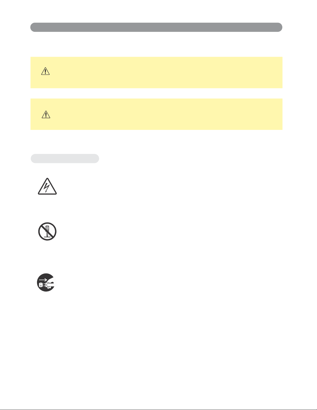
Typical Symbols
This symbol indicates an additional warning (including cautions).
A n i l l u s t r a t i o n i s p r o v i d e d t o c l a r i f y t h e c o n t e n t s ( f o r e x a m p l e :
the illustration to the left indicates danger of electrical shock).
This symbol indicates information that, if ignored,
could possibly result in personal injury or even death.
This symbol indicates information that, if ignored,
could result in personal injury or physical damage.
This symbol indicates a prohibited action.
indicated in an illustration or description near the symbol (for example:
the symbol to the left indicates that disassembly is prohibited).
This symbol indicates a compulsory action.
clearly indicated in an illustration or description near the symbol
( f o r e x a m p l e : t h e s y m b o l t o t h e l e f t s h o w s t h a t t h e p o w e r p l u g
s h o u l d b e d i s c o n n e c t e d f r o m t h e p o w e r o u t l e t ) .
he contents will be clearly
he contents will be
4
Page 6
Safety Instructions(continued)
r
r
r
WARNING
If a problem should occur
If smoke or strange odors arise, continued use could result in fire or electrical
shock. In such case, immediately turn off the power switch and then
disconnect the power plug from the power outlet. After making sure that
the smoke or odor has stopped, contact your dealer for repairs. Neve
attempt to make repairs yourself because this is dangerous.
Do not use this projector if there is no image or sound, or if the sound is
distorted. Continued use could result in fire or electrical shock. In such
case, immediately turn off the power switch; disconnect the power plug
from the power outlet and contact your dealer.
If water would enter the inside of this projector, immediately turn off the
power switch, disconnect the power plug from the power outlet and contact
your dealer.
Do not install on an unstable surface.
Do not install this projector on an unstable surface
such as a wobbly stand or incline because this could
result in the projector falling and causing injury.
Do not open the cabinet.
Never open the cabinet. There is high voltage inside
which can cause electrical shock. Contact your deale
for internal inspection, adjustment and repair.
Do not modify.
Do not modify this projector because this could result in fire or electrical shock.
Do not use in the bathroom or near water site.
Do not expose this unit to rain or use near water… for example, in the
bathroom, a wet basement, near a swimming pool, etc…
Do not insert objects into the Projector.
Do not insert metal objects through the ventilation openings, etc., of this
projector or drop such objects inside because this could result in fire o
electrical shock.
If a foreign object should enter this projector, immediately turn off
the power switch, disconnect the power plug from the power outlet
and contact your dealer.
Continued use could result in fire or electrical shock. Use special caution
household and where
in
children are present.
Page 7
Safety Instructions(continued)
r
WARNING
Do not look through the lens when the lamp is on.
Never look through the lens when the lamp is on. The powerful
light could adversely affect vision. Use special caution in
households where children are present.
Avoid shock or impact on the projector.
If the projector should fall, resulting in damage to the cabinet, immediately
turn off the power switch, disconnect the power plug from the power outlet
and contact your dealer.
Continued use could result in fire or electrical shock.
Do not place this projector in a container containing liquid. Do not
place flower vases, flowerpots, cups, cosmetics, liquids such as
water, etc., on top of this projector.
Do not use any power cable except those supplied with the
projector.
The use of any other power cable could result in fire or electrical
shock.
Do not shine the laser beam onto yourself or other.
The laser pointer function of projector remote control emits class
beam.
Do not look directly into the laser beam outlet or direct the laser beam
at other people. Vision can be impaired if the laser beam enters the eyes.
Especially pay attention if children are present
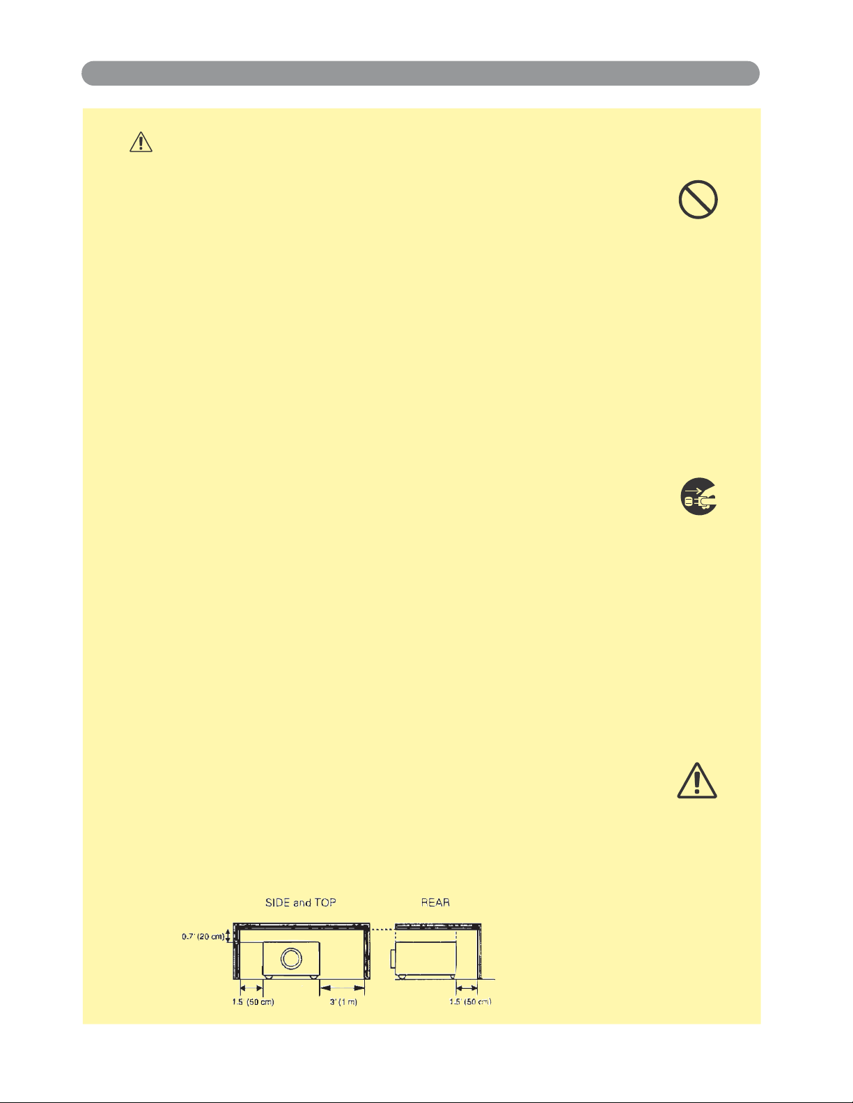
High temperatures are generated when the lamp is lit; so do not
place objects in front of the lens.
Allowing the proper amount of space on the top, sides, and rear of the
projector cabinet is critical for proper air circulation and cooling of the unit.
The dimension shown here indicate the minimum space required. If the
projector is to be built into a compartment or similarly enclosed, these
minimum distances must be maintained.
.
Ⅱ lase
6
Page 8

Safety Instructions(continued)
f
CAUTION
Placing heavy objects on top of this projector could result in loss
of balance or falling and cause personal injury or damage the
projector.
Do not block the ventilation openings.
Do not block the ventilation openings of this projector.
Blocking ventilation could lead to internal overheating which
could result in fire.
Do not place this projector on its side during use or push it into a small,
poorly ventilated location.
Do not place this projector on a carpet or bedding or cover it with a
tablecloth, etc. Also, when installing this projector, make sure the ventilation
openings are at least 30cm(12in) clearance around the projector.
Care and maintenance.
For safety purposes, disconnect the power plug from the power outlet
before starting the care and maintenance of this projector.
Battery usage.
Replace the batteries with the same type only.
Do not mix old and new batteries; this could result in fire or
personal injury due to battery cracking or leakage.
Make sure the plus and minus terminals are correctly aligned
when loading the batteries.
Incorrect loading could result in personal injury or contamination o
the surroundings due to battery cracking or leakage.
Have the projector interior cleaned regularly.
Contact your dealer to arrange for the service.
Accumulations of dust inside the projector can result in fire or
malfunction if not cleaned for an extended period.
Ask your dealer for details about internal cleaning.
7
Page 9
Safety Instructions(continued)
CAUTION
Avoid installation in humid or dusty locations. Do not install this
projector in a humid or dusty location. This could result in fire or
electrical shock.
Do not handle the power cord roughly. Keep the power cord away
from heaters;
The heat could melt the power cord and cause fire or electrical shock.
Do not touch the power plug with wet hands;
This could result in electrical shock.
When disconnecting the power plug, do not pull on the power cord.
This could damage the power cord and cause fire or electrical shock.
Always grip the plug when disconnecting.
When the projector is not to be used for an extended period.
If the projector is not to be used for an extended period because of
travel, etc., disconnect the power plug from the power outlet and
replace lens cover.
Compliance
Federal communications Commission Notice
This equipment has been tested and found to comply with the limits for a Class B digital device, pursuant to part 15
of the FCC Rules. These limits are designed to provide reasonable protection against harmful interference in a
residential installation. This equipment generates, uses, and can radiate radio frequency energy and, if not installed
and used in accordance with the instructions, may cause harmful interference to radio communications. However,
there is no guarantee that interference will not occur in a particular installation. If this equipment does cause harmful
interference to radio or television reception, which can be determined by turning the equipment off and on, the user
is encouraged to try to correct the interference by one or more of the following measures:
-Reorient or relocate the receiving antenna.
-Increase the separation between the equipment and receiver.
-Connect the equipment into an outlet on a circuit different from that to which the receiver is connected.
-Consult the dealer or an experienced radio/TV technician for help.
Use of shielded cable is required to comply with class B limits in Subpart B of Part 15 of FCC Rules.
Do not make any changes or modifications to the equipment unless otherwise specified in the instructions. If such
changes or modifications should be made, you could be required to stop operation of the equipment.
Model Number(s):LC-XIP2000
Trade Name :EIKI
Responsible party:EIKI
Address :30251 Esperanza Rancho Santa Margarita CA 92688-2132 U.S.A.
Telephone No. :800-242-3454(949-457-0200)
NOTE: This symbol and recycle system are applied only to EU
countries in the other area of world.
Please dispose of this equipment at your local community waste
collection/recycling centre. In the European Union there are separate
collection systems for used electrical and electronic products.
Please help us to conserve the environment we live in !
Your EIKI product is designed and manufactured with high quality materials and components
which can be recycled and reused.
This symbol means that electrical and electronic equipment, at their end-of-life, should be
disposed of separately from your household waste.
8
Voor de klanten in
Nederland
Bij dit product zijn batterijen
geleverd.
Wanneer deze leeg zijn, moet
u ze niet weggooien maar
Page 10
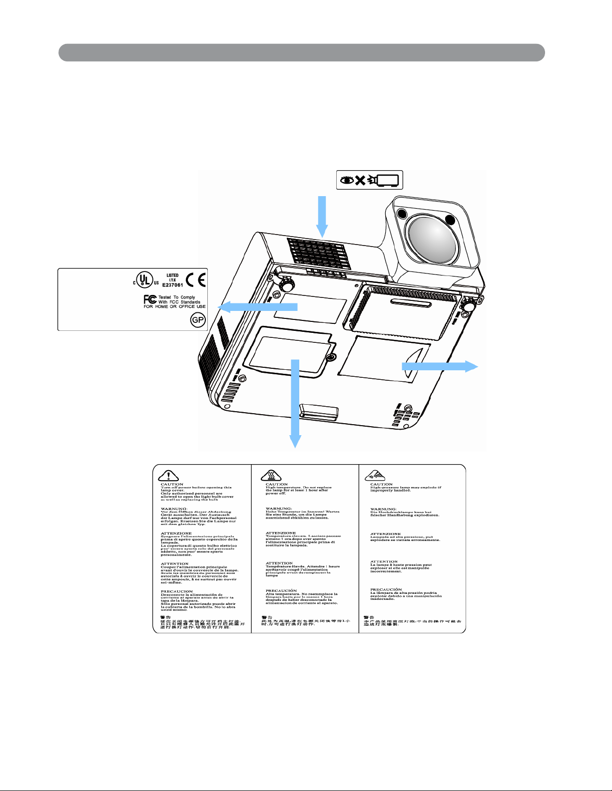
Location of product safety labels
Safety labels are used on or within the projector to alert you to items or areas
requiring your attention.
LABEL
EMI
EIKI
Model:LC-XIP2000
Input:
100-240V, 50/60Hz, 4A(1.2A~2.8A)
Serial no.:
LENS WARRANTY LABEL
LAMP WARNING LABEL
Business card
9
Page 11
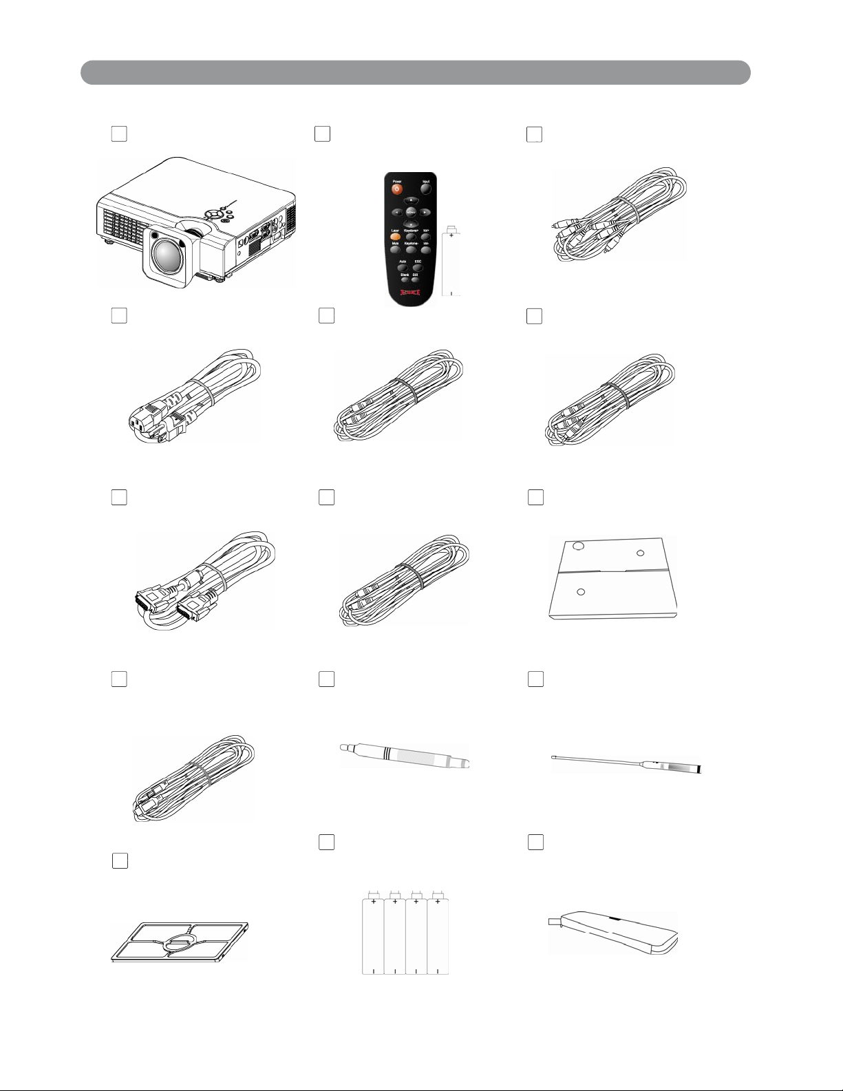
Checking the Package Contents
Projector
Remote Control
with batteries
Power Cord
Computer cable Speaker Cable
S-Video Cable
Video Cable
Audio Cable
Accessory Bag
USB Cable(1.5M)
Filter
Pen Pointer
Batteries
Hanging String
10
Page 12
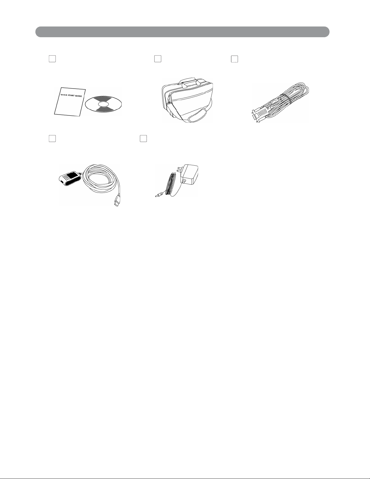
Checking the Package Contents
/
(Op
Quick Start Guide
Owner’s Manual CD
Extension USB
Cable(5M,Optional)
Carry Bag
(Optional)
Adapter
tional)
RS232 Cable
(Optional)
11
Page 13
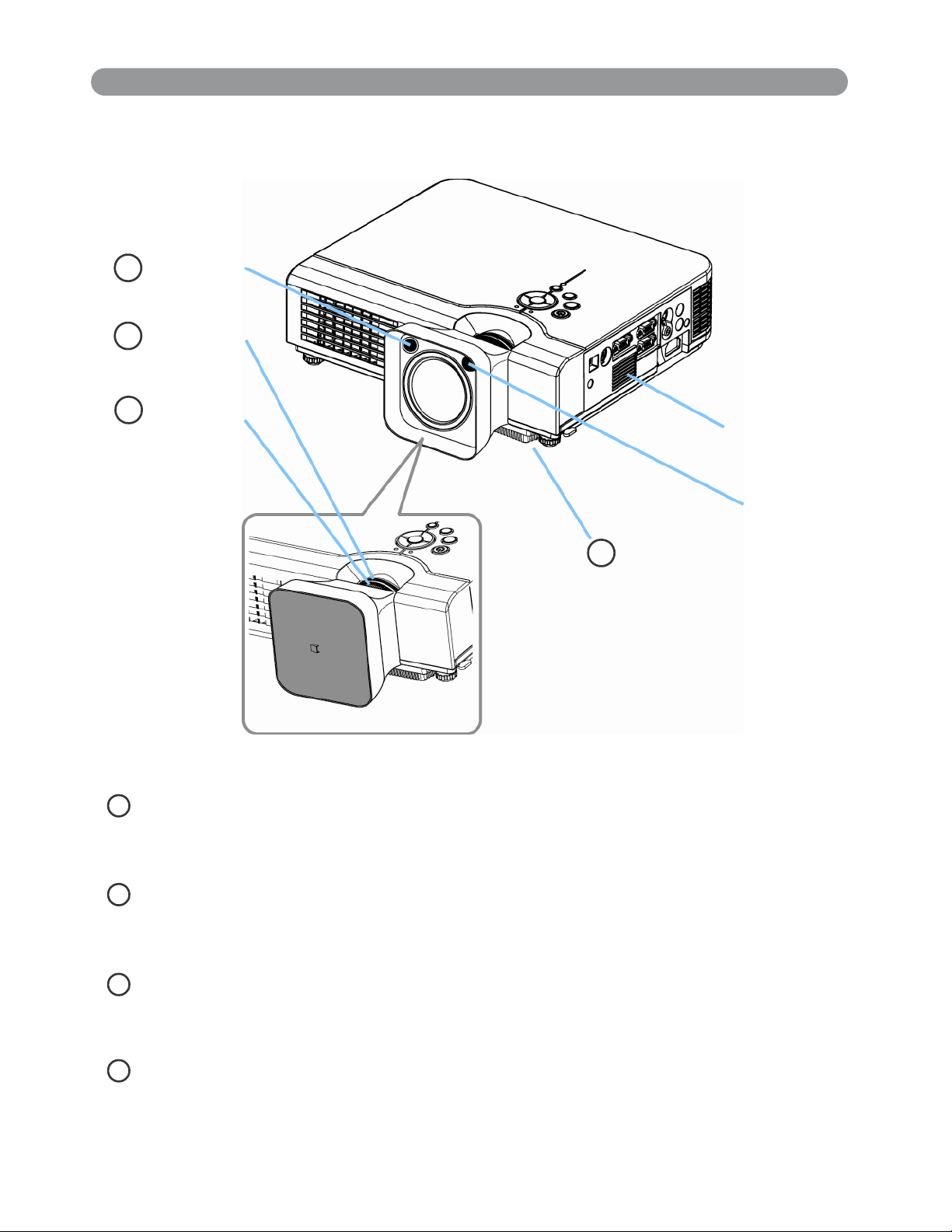
Part Names and Function:
Main Unit
IR sensor
3
1
Zoom ring
2
Focus ring
Speaker
CMOS sensor
4
Filter cover( bottom)
1
Zoom Ring
U s e t h e Z o o m R i n g t o a d j u s t t h e s i z e o f t h e p r o j e c t e d i m a g e .
R o t a t e t h e Z o o m R i n g u n t i l t h e i m a g e i s t h e d e s i r e d s i z e .
2
Focus Ring
U s e t h e F o c u s R i n g t o f o c u s t h e p r o j e c t o r i m a g e .
R o t a t e t h e F o c u s R i n g u n t i l t h e i m a g e i s c l e a r .
3
IR sensor
W h e n u s i n g t h e r e m o t e c o n t r o l , p o i n t t h e r e m o t e c o n t r o l a t t h i s
s e n s o r .
4
Filter cover
P r e v e n t d u s t a n d o t h e r f o r e i g n p a r t i c l e s f r o m b e i n g d r a w n i n t o
p r o j e c t o r . R e m o v e t h e F i l t e r c o v e r t o c l e a n t h e a i r f i l t e r .
12
Page 14
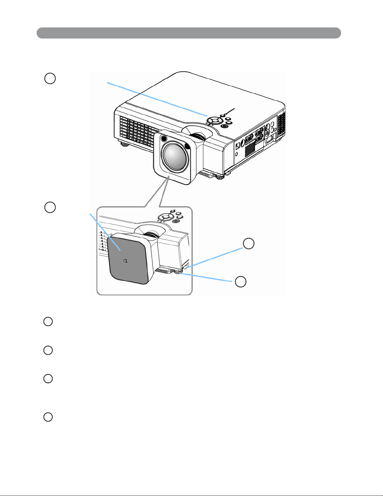
Part Names and Function:(continued)
r
Main Unit
8
Control panel
7
Lens cove
Foot adjust button
6
5
Front adjustable foot
5 Front adjustable foot
E x t e n d a n d r e t r a c t t o a d j u s t t h e p r o j e c t i o n a n g l e
6 Foot adjust button
L o c k / u n l o c k t h e a d j u s t a b l e f o o t .
7 Lens cover
A t t a c h w h e n n o t u s i n g t o p r o t e c t t h e l e n s f r o m b e c o m i n g d i r t y o r
d a m a g e d .
8 Control panel (keypad)
O p e r a t i n g s y s t e m .
13
Page 15
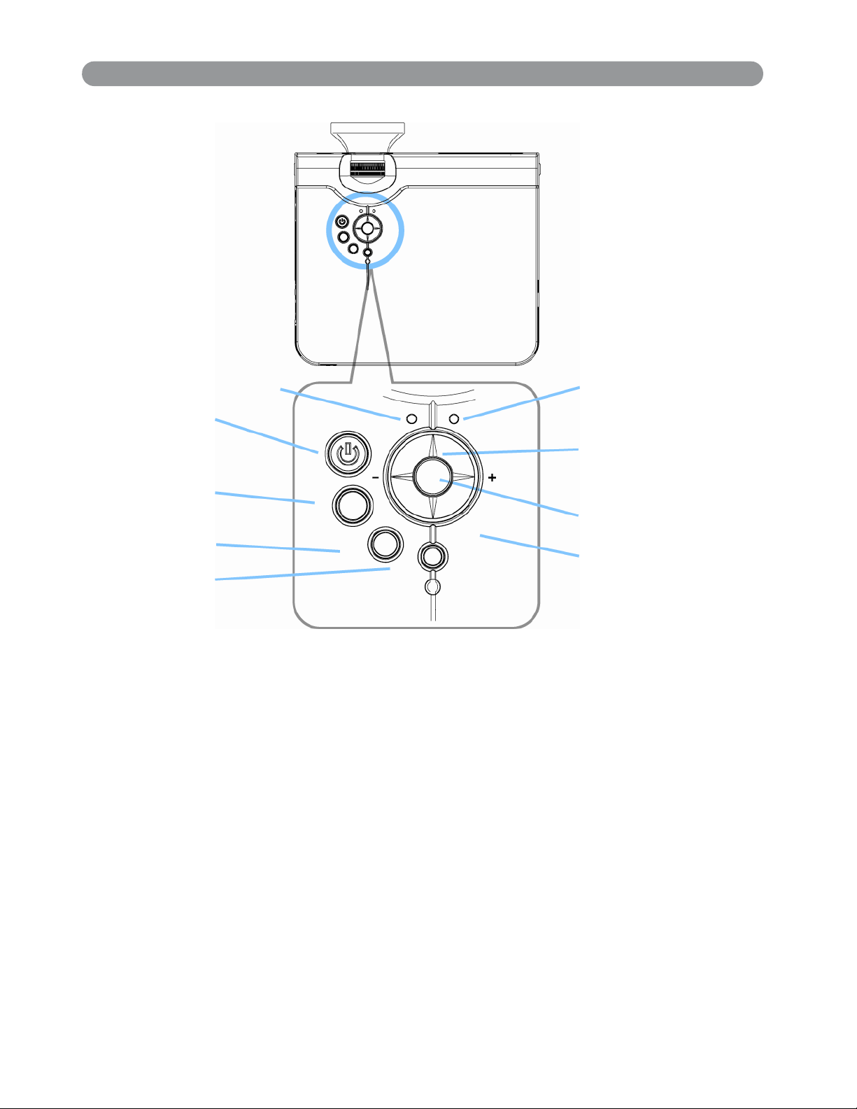
Part Names and Function:(continued)
Control panel
8. Power indicator
1. Power
4. Auto
2. Input
3. Blank
POWER LAMP
A
KEYSTONE
INPUT
BLANK
9. Lamp indicator
6. Menu-left/right,
Menu-up/down
5. Menu
7. Keystone
1. Power button
Power on / operation mode, Standby mode, Cooling-down mode
Brightness function,when sensor detects the surrounding light
lower than 150 lux,”power button”will turn into blue light.
2. Input
Selects between RGB input source-Computer in1→
Computer in 2(RGB or YPbPr) → AV→ S-Video→ Computer
in 1 , System will auto detect YPbPr or RGB signal in computer in
2 port.
3. Blank
Blanks the projected image. If the projector is left in blank mode
for more than 15 minutes, the projector will automatically shut
down.
4. Auto
Automatically adjusts the setting to match the current input.
14
Page 16
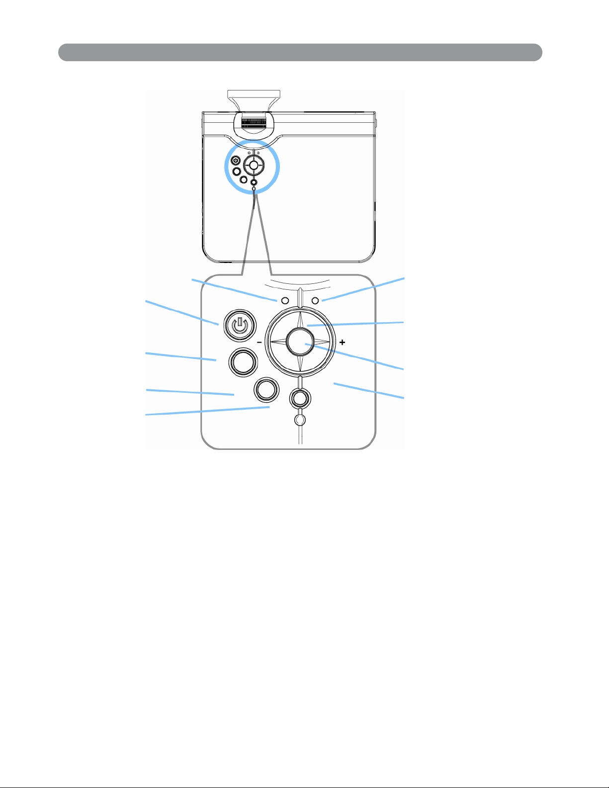
Part Names and Function:(continued)
Control panel
8. Power indicator
1. Power
4. Auto
2. Input
3. Blank
POWER LAMP
A
KEYSTONE
INPUT
BLANK
9. Lamp indicator
6. Menu-left/right,
Menu-up/down
5. Menu
7. Keystone
5. Menu
Display or hides the OSD main menu page.
6.Menu-up /down, Menu-right / left
Selecting OSD menu item up or down.
Selecting and adjusting the function of OSD menu item
7. Keystone
Adjusts the vertical keystone with menu-up, menu-down
(See Page 53)
8.Power indicator
Lights on or flashes to indicate the operating status of the projector
(See Page 73)
9. Lamp indicator
Indicate a problem in the internal projector temperature, lamp cover
or cooling down. (See Page 73)
15
Page 17
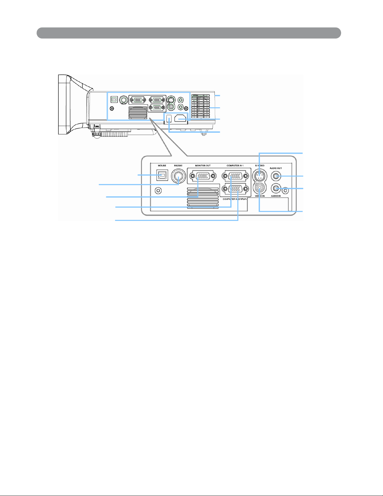
Part Names and Function:(continued)
n
Rear View / IO Board
12. Rear IR receiver
Inlet ventilation
10. Power socket
11. Power switch
5. S-video
9. USB mouse connector
4. RS-232C
3. Monitor out
1. Computer in 1
2. Computer in 2
/ YPbPr
1. Computer in 1
Input Analog RGB video signal from a computer
2. Computer in 2 / YPbPr
When input signal from computer in 2, it may encounter incorrect
picture color. Please press "Auto" button again. The picture will be
corrected.
3. Monitor out connector
Connect an external monitor to this connection view the Computer i
1
input.
7. Audio out
8. Audio in
6. Video in
4. Control (RS-232C)
Serial data port for controlling the projector with a computer or other
RS-232 control device.
5. S-Video connector
S-Video signal from a video source.
6. Video in
Component video signal from a video source.
16
Page 18
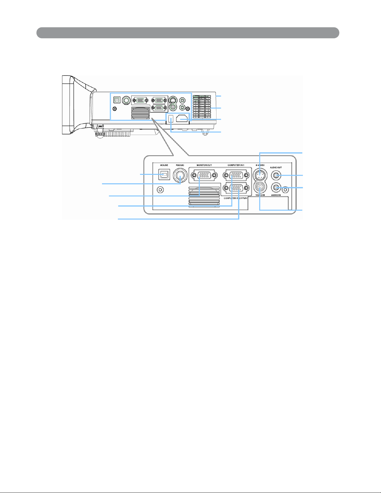
Part Names and Function:(continued)
r
Rear View / IO Board
9. USB mouse connecto
4. RS-232C
3. Monitor out
1. Computer in 1
2. Computer in 2
/ YPbPr
7. Audio out
Connecting to an external speaker system.
8. Audio in
12. Rear IR receiver
Inlet ventilation
10. Power socket
11. Power switch
5. S-video
7. Audio out
8. Audio in
6. Video in
Stereo mini jack for PC input
9. USB mouse connector
Connects a USB cable to a computer for interactive
smart function.
10. Power socket
Connects the power cord to this connection.
11. Power switch
Turns the power on/off.
12. Rear IR receiver
When using the remote control, point the remote control at this
sensor.
17
Page 19
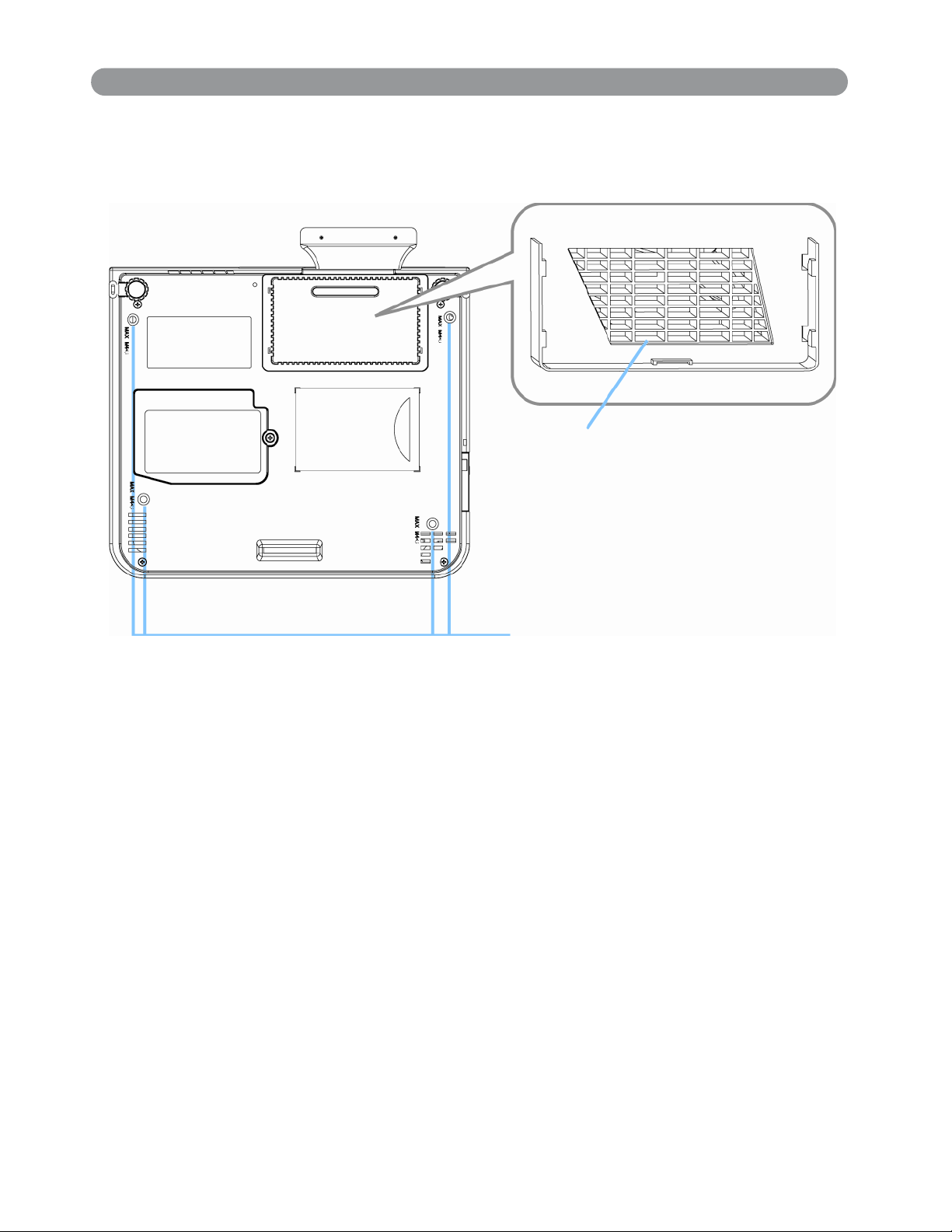
Part Names and Function:(continued)
Bottom View
Air filter cover
Suspension bracket fixing points(4)
1. Suspension bracket fixing points (4 points)
Install the optional ceiling mount here when suspending the projector
from the ceiling.
2. Air filter cover
Prevents dust and other foreign particles from being drawn into
the projector.
18
Page 20
Part Names and Function:(continued)
S
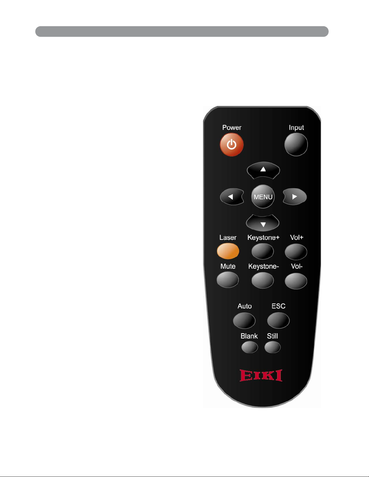
Remote Control
Power
Power on / operation mode, Standby mode,
Cooling-down mode
Esc
Press”ESC”button,it will close”Menu”picture
Vol +/-
Sound louder or lower
Menu
Display or hide the OSD main menu page
Keystone +/-
Adjusts the vertical keystone function
till
Keep the current image on the Screen
Blank
Hide the current image,become black color
on the screen
Auto
Refresh the current image
Menu up/down, Menu left/right
Selecting and adjusting the function of OSD
INPUT source
Select input source: Computer 1 → Computer 2
→ Composite Video →S-Video → Computer 1
19
Page 21
Part Names and Function:(continued)
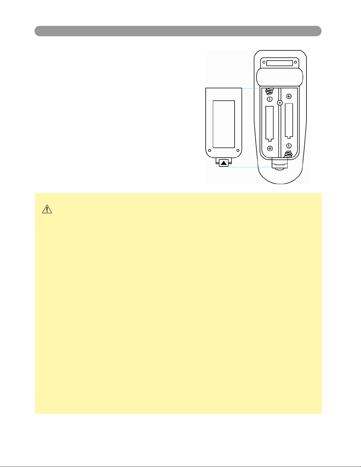
Remote Control Batteries Installation
1. Remove the battery cover.
2. Loading the batteries.
Make sure the plus and minus poles are
correctly oriented.
3. Close the battery cover.
U M - 4 ( A A A )
R O 3 . 1 . 5 . V X 2
C A U T I O N
1. Avoid excessive heat and humidity.
2. Do not drop the remote control.
3. Do not expose the remote control to water or moisture, this could
result in malfunction.
4. When the remote control will not be used for an extended period,
remove the batteries.
5. Replace the batteries when remote control operation becomes
sluggish or unresponsive.
6. Do not place the remote control close to the cooling fan of the
projector.
7. Do not disassemble the remote control. If the remote control
needs service. Please bring it to the service station.
20
Page 22
Installation
”
”
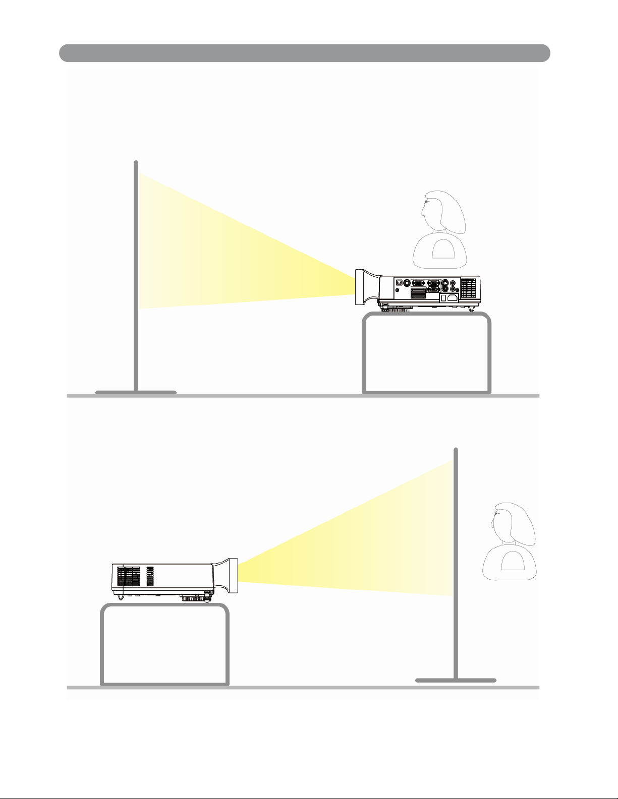
Setting Up the Projector
The projector supports the following four different projection methods
Front projection
150
Rear
150
A special method of
installation is required in order to suspend the
projector from the ceiling. Please ask your dealer for details.
21
Page 23
Installation(contiuned)
”
”
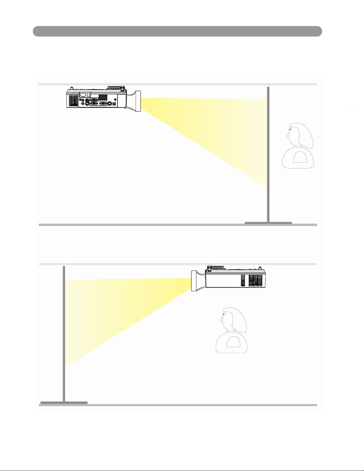
Setting Up the Projector
Rear ceiling projection
150
Front ceiling projection
150
A special method of
installation is required in order to suspend the
projector from the ceiling. Please ask your dealer for details.
22
Page 24
Installation(contiuned)
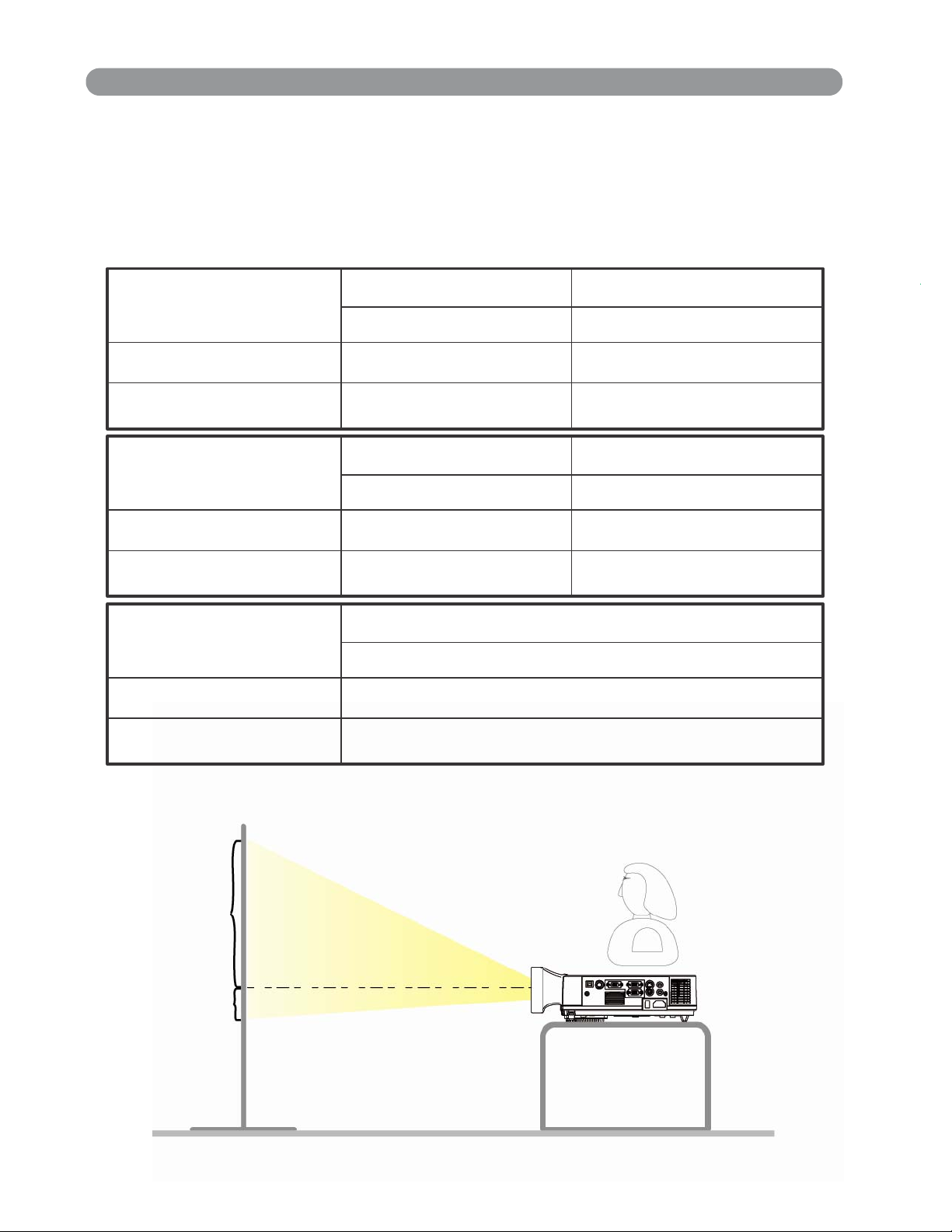
Size and Projection Distance
The distance between the projector and screen determines the
actual image size. Refer to the table below to determine the image
size at a given distance.
The values shown below are approximate and may vary from actual sizes.
5 0”
Screen Size (inches)
(WxH) mm
Zoom(min) 3 . 8 ’ ( 1 . 2 m ) 4 . 6 ’ ( 1 . 4 m )
Zoom(max)
Screen Size(inches)
(WxH) mm
Zoom(min) 6 . 2 ’ ( 1 . 9 m ) 7 . 8 ’ ( 2 . 4 m )
Zoom(max)
1 0 1 6 x 7 6 2 1 2 1 9 x 9 1 4
3 . 3 ’ ( 1 . 0 m ) 3 . 8 ’ ( 1 . 2 m )
8 0 ”
1 6 2 6 x 1 2 1 9 2 0 3 2 x 1 5 2 4
5 . 2 ’ ( 1 . 6 m ) 6 . 5 ’ ( 2 . 0 m )
6 0 ”
1 0 0 ”
Screen Size(inches)
(WxH) mm
Zoom(min) 1 1 . 9 ’ ( 3 . 6 m )
Zoom(max)
A
B
A:B Ratio=6.5:1
1 5 0 ”
3 0 4 8 x 2 2 8 6
9 . 9 ’ ( 3 . 0 m )
23
Page 25

Installation(contiuned)
Adjusting the Image Position
Use the adjustable foot at the front of the projector to set the image
height.
tune
Rotate the adjustable foot at the rear of the projector to fine-
the image position.
When the foot is adjusted, it may cause the shape of the projected
to
image
correct
become distorted. Use the keystone correction function to
this distortion.
To retract the front adjustable foot, press the foot adjust button. The
front
adjustable foot will slowly retract inside the projector.
24
Page 26

Installation(contiuned)
r
t
y
Moving the projector
1. Use the carry bag when moving the projector.(option)
2. Replace the lens cover and retract the front adjustable foot when
moving the projector to prevent damage to the projector.
carry bag
( O p t i o n a l , p l e a s e c o n t a c t y o u r d e a l e r f o r m o r e i n f o r m a t i o n )
C A U T I O N
The optional carry bag is intended to protect the projecto
from dust and scratches on the surface of the cabinet. It is
designed to protect the projector from external shock.
not
Do not transport the projector in an unsuitable transpor
case when using a courier or transport service. This ma
cause damage to the projector.
25
Page 27

Installation(contiuned)
Software and Hardware install
1.Section one : System Requirements
System Requirements
OS Required Microsoft Windows 2000/XP(SP2)
Processor Type
RAM
Min. Free disk space
CD-ROM Driver & available USB 2.0 port
2.Section two : Software and Hardware driver installation
Intel Pentium IV or above
256 MB or above
30 MB
Step 1: Insert the Disc to the PC.
Step 2: Execute setup.exe
Step 3: Next
26
Page 28

Installation(contiuned)
Software and Hardware install
2.Section two : Software and Hardware driver installation
Step 4: Install
27
Page 29

Installation(contiuned)
Software and Hardware install
2.Section two : Software and Hardware driver installation
Step 5: Finish (“LightPen” software installation)
28
Page 30

Installation(contiuned)
Software and Hardware install
2.Section two : Software and Hardware driver installation
Step 6: Next (Continue to install driver for CMOS hardware)
29
Page 31

Installation(contiuned)
Software and Hardware install
2.Section two : Software and Hardware driver installation
Step 7: Install
30
Page 32

Installation(contiuned)
Software and Hardware install
2.Section two : Software and Hardware driver installation
Step 8: Continue Anyway
NOTE: We confirmed that installation of this software will not impair or destabilize
the correct operation of your system.
31
Page 33

Installation(contiuned)
Software and Hardware install
2.Section two : Software and Hardware driver installation
Step 9: Finish
32
Page 34

Installation(contiuned)
Software and Hardware install
2.Section two : Software and Hardware driver installation
Step 10-A: Turning on the projector
POWER
Remove the lens cover.
Connect the projector’s power cable with the projector, and insert
the power cable into a wall socket.
Turn on the AC power switch of the projector.The power indicator
lights
green
and slowflashing. Projector works in standby mode.
Press the power button to turn on the projector. The power LED
begins to green and lamp LED begins to red, and the projector
lamped on.
be
will
33
Page 35

Installation(contiuned)
Software and Hardware install
2.Section two : Software and Hardware driver installation
Step 10-B: Turning on the projector
WARNING
If no image are projected, change the input signal.
POWER
A
INPUT
BLANK
LAMP
KEYSTONE
When using a laptop or a PC with an in built monitor, select external
video
output on the computer.
34
Page 36

Installation(contiuned)
Software and Hardware install
2.Section two : Software and Hardware driver installation
Step 11: Connecting PC to the projector
To connect Computer cable (RGB) first then USB cable.
USB port
To Computer monitor port
Mouse port
USB cable
Computer cable
Computer
in 1 or
Computer
in 2
35
Page 37

Installation(contiuned)
Software and Hardware install
2.Section two : Software and Hardware driver installation
Step12:Select “No, not this time” than “Next”
36
Page 38

Installation(contiuned)
Software and Hardware install
2.Section two : Software and Hardware driver installation
Step13: Next
37
Page 39

Installation(contiuned)
Software and Hardware install
2.Section two : Software and Hardware driver installation
Step14: Continue Anyway
NOTE: We confirmed that installation of this software will not impair or destabilize
the correct operation of your system.
Step15: Finish
“LightPen” shortcut will be added on the window
desktop automatically.
38
Page 40

Installation(contiuned)
3.Section three: Functional key of “Pointer”
LED lamp
Button:Mouse left key
39
Page 41

Installation(contiuned)
“Lig
4.Section four: Calibration
Step 1: Execute “LightPen” shortcut
desktop.
Step 2: Select
key for Calibration.
htPen” from toolbar then click mouse right
on the Windows
40
Page 42

Installation(contiuned)
g
4.Section four: Calibration
Step 3: Push the button of “Pointer” and point to the
“center of green cross target” from upper-left of screen
to lower-right of screen orderly. There are nine targets
totally. No more green target on the screen means you’ve
completed the calibration procedure. To keep the angle
of “Pointer” as constant as possible durin
for more accurate positioning.
the calibration
41
Page 43

Installation(contiuned)
4.Section four: Calibration
How to play function of “Mouse right key”?
Point to top or down of screen outside than push the
button of “Pointer”.
42
Page 44
Installation(contiuned)
4.Section four: Calibration
There is another quick way to change the position of icon or
hide it.
Point to left or right of screen outside then push the button
of “Pointer”.
43
Page 45

Installation(contiuned)
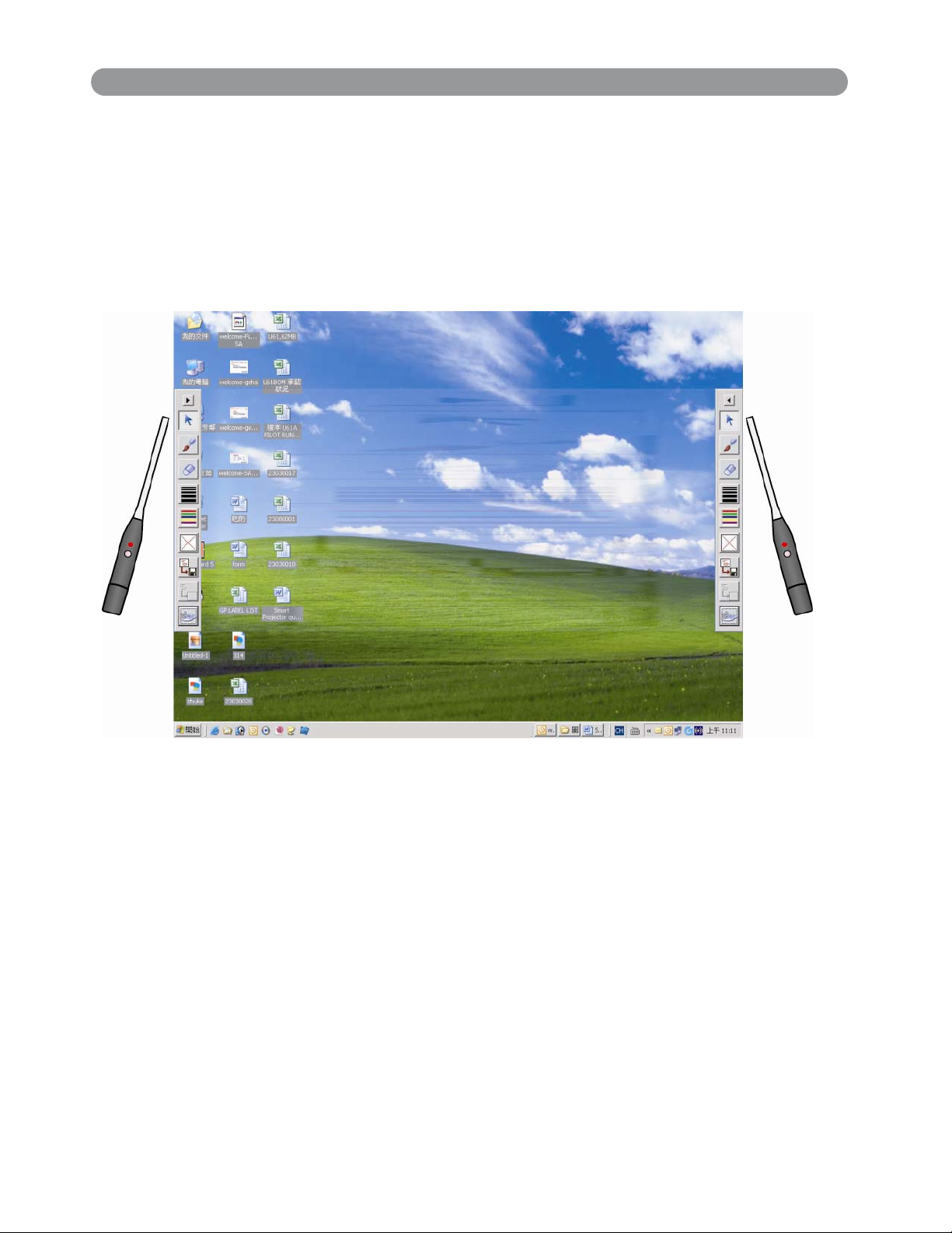
5.Section five: Function of icon
Icon position
P u s h t h e b u t t o n o f “ P o i n t e r ” t o s e l e c t i c o n ’ s position
on either the right-side or left-side of screen.
Mouse
Pen
Eraser
Select
the fineness of pen
Select
the color of pen
Erase all
Save
files
Redraw
Virtual
keyboard
44
Page 46

How to Connect
Desktop PC
Before starting, make sure that the projector and computers are both
turned off.
1. Connect the computer cable.
Connect either end of the computer cable to the projector’s Computer
in 1 or Computer in 2
Disconnect
other
from
end of the terminal where the monitor cable is disconnected
the computer.
the monitor cable from the computer and connect the
If needed, connect the monitor cable of the computer monitor to
the
projector’s Monitor Out.
Tighten the screw on all connectors.
2. Connect the audio cable if necessary.
Connect one end of the audio cable to the Audio in jack on the
projector.
Connect the other end of the audio cable to the audio output port
on the computer sound card.
VGA
Desktop PC
45
Page 47

How to Connect
Laptop PC
Before beginning, make sure that the projector and computers are both
turned
1. Connect the computer cable.
off.
Connect either end of the computer cable to the projector’s
Computer
in 1.
Connect the other end of the project cable to the monitor out
connection
on
the laptop.
Tighten the all connectors.
2. Connect the audio cable if necessary.
Connect one end of the audio cable to the Audio in jack on the
projector.
Connect the other end of the audio cable to the audio output port
on the laptop PC.
Laptop PC
46
Page 48

How to Connect
Video
1. Connect to a video source
The Projector can receive composite AV ,YPbPr and S-Video.
Connect RCA plug at projector and video source ( like DVD
player) for video signal. Please contact with your dealer for
optional cable.
2.
Connect RCA plug ( white and red) to audio source ( like DVD
player) and connect the phone jack to projector for audio
signal.
47
Page 49

How to Connect
Video
3.
Connect YPbPr plug at projector computer in 2 port and video
source
4.
For S-Video, using S-Video cable connect to projector and
(
like DVD player) for video signal.
video source for video signal.
48
Page 50

Basic Operation
Turning on the projector - Procedure
1.
Check the power is turned off for the projector and all components
connected to the projector.
2.
Remove the lens cover.
3.
Connect the power cord to the projector.
4.
Turn on the power switch.
5.
Press the button on the control panel or [POWER] button on
the remote control.
1
2
5
3
A
KEYSTONE
INPUT
BLANK
4
49
Page 51

Basic Operation
g
Turnin
6.
The power indicator will flash green.
7.
Press the Input button on the control panel or on the
on the Projector - Procedure
remote control to select the appropriate source.
8.
Rotate the zoom ring to adjust the screen size.
9.
Rotate the focus ring to adjust the focus.
6
POWER
LAMP
9
8
6
KEYSTONE
INPUT
BLANK
50
Page 52

Basic Operation
g
Turnin
1.
Press the power button on the projector or remote control. The
power
2.
Press the power button again and the projector will enter cool-down
off the Projector - Procedure
off confirmation message appears .
mode. The lamp shuts off, the lamp indicator flashes red, and the
fans
down
or remote control buttons.
3.
continue to run for approximately two minutes. During the cool
sequence the projector will not respond to any control panel
Do not set the power switch to off or unplug the
C A U T I O N
projector during the cool-down sequence. Not allowing
the lamp to cool properly will greatly reduce the life
of the lamp.
After the cool-down sequence is completed the fans will shut off
and the lamp indicator will stop flashing. The projector is now in
standby mode and can be turned back on with the remote control
or control panel. If the projector will not be used for an extended
period, set the power switch to off and disconnect the power cord.
51
Page 53

Basic Operation
j
y
Ad
ust the Screen Image
1. Adjusting the image size
Rotate the Zoom Ring to adjust the image.
2. Adjusting the image height
Extend or retract the front adjustable foot to adjust the height of
image.
the
3. Correcting Keystone Distortion
◆
Press the Keystone button on the control panel.
◆
Keystone correction message will be appeared.
◆
Press ”Left/Right” button to correct Keystone distortion.
POWER
LAMP
Press ”Left button” to
correct ke
stone distortion.
INPUT
BLANK
KEYSTONE
Press ”Right button” to
correct keystone distortion.
52
Page 54

Functions of Menu (OSD)
g
Keypad Operatin
1.Power
5.Menu
3.Auto
4.Input
1.
Turn on and turn off
:
POWER
LAMP
6.Menu-Up/Down
Menu-Left/Right
A
INPUT
BLANK
KEYSTONE
7.Quick Key
2.Blank
the projector
2. Blank : Blanks the projected image. If
the projector is left in Blank
m o d e f o r m o r e t h a n 1 5 m i n u t e s , t h e p r o j e c t o r w i l l
automatically
shut off the lamp and enter cool-down mode.
3. Auto : Automatically adjusts the settings to match the current input.
4.
Input :
5. Menu : Enter or exit the main menu (Show and hide the OSD)
6. : Up
Selects VIDEO or PC input source.
/
Down arrow buttons, used
to navigate through the OSD Menus.
: Right / Left arrow buttons, used to select and adjust OSD Menu
functions.
7. Quick Key : It can be selected the “Keystone/Brightness/
Contrast/Volume” by pressing “bottom” of MENU
button and adjusted by pressing “Left/Right” bottom
of MENU button on the control panel or remote
control.
There is a
well.
“Quick Key“ on the remote control and projector keypad as
53
Page 55

Functions of Menu (OSD)
Computer Mode-Picture Menu
1. PICTURE
Brightness 000/100 Adjusts the overall image brightness
Contrast 000/100 Adjusts the difference between
light and dark areas of the image
Sharpness 000/002 Adjusts the image sharpness
Display mode
Video
Presentation
Natural
Green board
User
User Red
User Green
User Blue
Select
Keep the soft tender color
For computer presentation use
Nature color
When using on green board
Adjustments of each RGB color
000/100
000/100
000/100
54
Page 56

Functions of Menu (OSD)
Computer Mode-Audio Menu
Volume
Mute
2. AUDIO
000/040
Off/on
Adjusts the volu
Mutes the volume on/off
me
55
Page 57

Functions of Menu (OSD)
Computer Mode-SETTING Menu
H position
V position
Phase
Frequency
Auto keystone off/on
Keystone V
Auto sync execute
Auto search
000/100 Move the image position horizontally
000/100 Move the image position vertically
000/100 Set the synchronization polarity
000/100 Set the horizontal scanning frequency
-80/+80
off/on
3.SETTING
Automatically Corrects keystone
distortion in image i.e. press once
to do once
Corrects vertical keystone distortion
in image
Sets all of the above
settings automatically
Search signal source automatically.
56
Page 58

Functions of Menu (OSD)
Computer Mode-ADVANCED Menu
57
Page 59

Functions of Menu (OSD)
Computer Mode-ADVANCED Menu
4.ADVANCED
Zoom/pan execute Execute digital zoom and pan function
Still on/off Freezes the current image on the screen.
Blank on/off Hide the image, displays a blank, black
screen*(see below)
Reset all execute
Language English
Resets all OSD Menu function to their factory
default values*( see below)
Select the language that the OSD Menu and on
screen massage are display in English / German
/ French / Spanish / Italian
Dutch / Swedish / Chinese(Simplied-Tranditinal)
/ Korean / Russian / Japanese
/ Portuguese /
Resize
Select source execute Select the input source from:
logo
scale mode Normal/True Provide the image in its original size. When the
Blank on
If the projector is left in Blank mode for more than 15 minutes, the
projector will automatically shut off the lamp and enter cool-down
mode.
Reset all
1. After you select [reset all] on the OSD menu, the following confirmation
message will appear on the screen.
on/off on—factory-set logo
4:3
Computer 1 / Computer 2 (RGB or YPbPr)
/ Video / S-Video
off—blue image only.
original image size larger than the screen size
(1024x768), this projector enters panning mode
automatically.
2. Press reset button on the remote control or the button on the control
panel to reset the OSD Menu values. Press the ESC button or ignore the
message to exit the Reset All function without changing any settings.
58
Page 60

Functions of Menu (OSD)
Computer Mode-PRESENTATION Menu
5.PRESENTATION
Auto ceiling off/on
Front execute Normal projection mode
Ceiling
Rear
Ceiling and
Rear
Auto
Brightness
Lamp mode
execute
execute
execute
off/on
normal
economic
Automatically inverts the image when
the projector is turned upside down i.e.
when the projector is mounted on the
ceiling
Inverts the image vertically, used when
the projector is mounted upside down
Inverts the image horizontally, used when
projecting onto a rear projection screen
Inverts the image horizontally and vertically,
used when the projector is mounted upside
down and projecting onto a rear projection
screen
Auto detects brightness; it turns to economic
mode automatically when the brightness is
low.
Economic mode reduces the lamp brightness
economic to extend lamp life and quiet the
projector
Lamp
Reset lamp
timer
(optional)
execute
Show Lamp timer
After changing a new lamp,execute this
function for reset the Lamp timer.
(see below)
59
Page 61

Functions of Menu (OSD)
g
g
Reset Lamp Timer
1. After you select
〔Reset Lamp Timer〕on the OSD menu, the followin
confirmation message will appear on the screen.
2.You choose
* The replacement warnin
〔Yes〕,the Lamp Mode show〔0〕.
message is set to appear after about 2000
hours of lamp use in order to maintain the brightness and quality
projected images. When the lamp replacement message appears,
replace the lamp(part number 23040007) with a new one as soon as
possible, even if it is still working.
of the
60
Page 62

Functions of Menu (OSD)
Video Mode-Picture Menu
1. PICTURE
Brightness 000/100 Adjusts the overall image brightness
Contrast 000/100 Adjusts the difference between
light and dark areas of the image
Sharpness 000/002 Adjusts the image sharpness
Display mode
Video
Presentation
Natural
Green board
User
User Red
User Green
User Blue
Select
Keep the soft tender color
For computer presentation use
Nature color
For Green board uses
adjustments of each RGB color
000/100
000/100
000/100
61
Page 63

Functions of Menu (OSD)
Video Mode-Audio Menu
Volume
Mute
2. AUDIO
000/040
Off/on
Adjusts the volu
Mutes the volume on/off
me
62
Page 64

Functions of Menu (OSD)
g
Video Mode-Settin
Menu
Auto keystone off/on
Keystone V
Auto search
-80/+80
off/on
3.SETTING
Automatically Corrects keystone
distortion in image i.e. press once to
do once
Corrects vertical keystone distortion in
image
Search signal source automatically.
63
Page 65

Functions of Menu (OSD)
Video Mode-Advanced Menu
64
Page 66

Functions of Menu (OSD)
Video Mode-Advanced Menu
4.ADVANCED
Zoom/pan execute Execute digital zoom and pan function
Still on/off Freezes the current image on the screen.
Blank on/off Hide the image, displays a blank, black
screen*(see below)
Reset all execute
Language English
Resets all OSD Menu function to their factory
default values*( see below)
Select the language that the OSD Menu and on
screen massage are display in English / German
/ French / Spanish / Italian
Dutch / Swedish / Chinese(Simplied-Tranditinal)
/ Korean / Russian / Japanese
/ Portuguese /
Resize
Select source execute Select the input source from:
logo
scale mode Normal/True Provide the image in its original size. When the
blank on
If the projector is left in Blank mode for more than 15 minutes, the
projector will automatically shut off the lamp and enter cool-down
mode.
Reset all
1. After you select [reset all] on the OSD menu, the following confirmation
message will appear on the screen.
on/off on—factory-set logo
4:3
Computer 1 / Computer 2 (RGB or YPbPr)
/ Video / S-Video
off—blue image only.
original image size larger than the screen size
(1024x768), this projector enters panning mode
automatically.
2. Press reset button on the remote control or the button on the control panel
to reset the OSD Menu values. Press the ESC button or ignore the message
to exit the Reset All function without changing any settings.
65
Page 67

Functions of Menu (OSD)
Video Mode-PRESENTATION Menu
5.PRESENTATION
Auto ceiling off/on
Front execute Normal projection mode
Ceiling
Rear
Ceiling and Rear
Auto Brightness off/on
Lamp mode
execute
execute
execute
normal
economic
Automatically inverts the image when
the projector is turned upside down i.e.
when the projector is mounted on the
ceiling
Inverts the image vertically, used when
the projector is mounted upside down
Inverts the image horizontally, used when
projecting onto a rear projection screen
Inverts the image horizontally and vertically,
used when the projector is mounted upside
down and projecting onto a rear projection
screen
Auto detects brightness; it turns to economic
mode automatically when the brightness is
low.
Economic mode reduces the lamp brightness
economic to extend lamp life and quiet the
projector
Lamp
Reset lamp
timer (optional)
66
execute
Show Lamp timer
After changing a new lamp,execute this
function for reset the Lamp timer.
(see below)
Page 68

Appendix
Technical Specifications
Mechanical Information
Projector Type Multi-media Projector
Dimensions (W x H x D) 12.20” x 3.78” x.10.63” (310 mm x 96 mm x 270 mm)
(excluding adjustable feet)
Net Weight 7.7 lbs (3.5 kg)
Feet Adjustment 0° to 14°
Panel Resolution
LCD Panel System 0.63” TFT Active Matrix type, 3 panels
Panel Resolution 1,024 x 768 dots
Number of Pixels 2,359,296 (1,024 x 768 x 3 panels)
Signal Compatibility
Color System PAL, SECAM, NTSC, NTSC4.43, PAL-M, and PAL-N
High Definition TV Signal 480p, 720p and 1080i
Scanning Frequency H-sync. 15 kHz–69 kHz, V-sync. 43–85 Hz
Optical Information
Projection Image Size (Diagonal) Adjustable from 40” to 300” (Interactive smart function is
available form 50”~150”)
Throw Distance 2.6’–19.8’ (0.8 m–6.0 m)
Projection Lens F1.6–1.88 lens with f18.6 mm–22.3 mm with manual zoom and
focus
Projection Lamp
Interface
Video Input Jack RCA Type x 1
S-video Input Jack Mini DIN 4 pin x 1
Audio Input Jacks Mini Jack x 1
Computer Input Analog RGB (Mini D-sub 15 pin) Terminal x 1
Computer Input Analog RGB (Mini D-sub 15 pin) Terminal x 1 / YPbPr
Monitor Output
Service Port
USB Connector
Audio Output Jack Mini Jack x 1
Audio
Internal Audio Amp 3.0 W RMS
Built-in Speaker 2 W mono
Power
Voltage and Power Consumption AC 100–120 V , 50/60 Hz (The U.S.A and Canada)
Operating Environment
Operating Temperature 41°F–95°F (5 °C–35 °C)
Storage Temperature 14°F–140°F (-10°C–60 °C)
Remote Control
Battery AAA x 2
Operating Range 13.2’ (4 m)/±30°
Dimensions 1.7” (W) x 0.8” (H) x 4.3” (D) (44 mm x 20 mm x 108 mm)
Net Weight
Laser Pointer
200 W
Analog RGB (Mini D-sub 15 pin) Terminal x 1
Connector Mini DIN 8 pin x 1
USB Series B connector x 1
AC 200–240 V , 50/60 Hz (Continental Europe)
250W(ECO mode 210W) ,Standby 2W
56 g (including batteries)
Class II Laser (Max. Output: 0.9 m W/Wave length: 645–660 nm)
67
Page 69

Maintenance and Troubleshootin
g
Ceiling Mounted Installation Guide
Attach the optional ceiling mount at four-suspension bracket fixing points when
suspending the from a ceiling.
A special method of installation is required in order to suspend the
projector from the ceiling. Please ask your dealer for more details.
68
Page 70

Maintenance and Troubleshootin
g
g
g
R
R
1.Cleaning the projector
Clean the projector cabinet by wiping it gently with a soft cloth.If necessary,
the cabinet can be cleaned usin
a neutral detergent and a soft cloth ensure th
case
WARNING
2.Cleanin
the lens
Always unplug the projector before performing any
maintenance.
Use a commercially available air blower, or use lens cleaning paper and lens
cleaner approved for use on optical coatings.
Do not clean the lens with harsh materials or subject the lens to shock, as it
can easily become damaged. Close the lens cover when the projector not
in use.
3.Change Air Filter
When the air filter becomes clogged with dust, etc., the projector may overheat
and turn itself off to prevent internal damage.
Clean the air filter every 100-hours.
*If the filter is difficult to clean or if it is deteriorating, it should be replaced
1.Remove the filter cover from the bottom of projector.
2.Pull out the air filter.
3.Install the new air filter.
AI
FILTER COVE
69
Page 71

Maintenance and Troubleshootin
g4.Q
g
f
Q
e
g
h
Q
g
.
Q
g
: Why can’t install the program?
A: You might need to log in as “administrator” to be able to install program to
your computer. Consult with your I/T engineers to help you in this case.
In addition, pro
ram will be deleted if you install twice due to the setting o
program. In this case, please install again.
5.
: Why is it showing “No lightpen found”?
A: The possible reasons for this might be:
(1).USB cable not well connected
Please check and make sure the cable is well connected between PC and
Projector.
* Some Anti-virus program will disable the USB port. Please close th
anti-virus program and start the “LightPen” program again.
(2).USB driver is not well installed
(3).The len
than 1.5M.
th of USB cable is too long. The USB cable should be shorter
If you would like to require longer cable then please
purchase proper USB extension cable from your dealer.
(4).USB port on computer malfunction
Please check if the USB port is functioning. If not, please consult wit
I/T engineer.
Some note book computer will disable USB ports when the battery is low.
Please try to use AC power. Some note book computers do not
provide standard 500mA to the USB ports or the USB converter is not
working properly, in this case please use our standard USB cable.
: Why the green cross target does not appear after running lightpen
6.
calibration?
A: This is signaling too weak caused by using USB cable either poor quality or
too lon
. Try a better quality USB cable or use proper USB extension cable
7.Q: Why can’t I make the green cross target turn into black in calibration
procedure?
A: Possible reasons are the wand or light pen is out of battery or the system
not working properly caused by strong ambient light interference.
8.Q: Why the green cross target turns into black itself?
A: This is caused by strong ambient light interference. Try to control the
ambient light.
: What is considered as “strong ambient light interference”?
9.
A: Strong ambient light is usually caused by the following:
(1).Sun light direct projection on the screen. You can use curtain to avoid this.
(2).Tun
sten lamp working close to the sensor. Try to move the tungsten
lamp away from the sensor or switch it off.
70
Page 72

Maintenance and Troubleshooting
Q
f
Q
Q
Q
10.
11.
12.
: Why is the cursor not at the position pointed?
The possible reasons for this are:
A:
(1).The system not been well calibrated. Try to point to the “center” of green
cross target when you running calibration.
(2).The position o
(3).The image resolution been changed
Run the calibration procedure again will solve the problem.
: Why is the lightpen not working?
A: The reasons for this are:
(1).When using lightpen device, writing in shadow area won’t work as the
signal can’t be received by the sensor.
(2).Lightpen battery is low or battery cap is loose
(3).Strong ambient light interference.
(4).USB cable not well connected.
: Why is the cursor jumping?
A: This is caused by strong ambient light interference. Try to avoid
strong ambient light interference especially strong sun light directly
projection on the screen.
the projector, screen or projection size has been changed
.
13.
Remarks
1.The lightpen is working on light signal. Strong ambient light interference will
2.When using lightpen device, writing in shadow area won’t work as the signal
3.The operation system must be Windows 2000 service pack 2 and above.
4..It is required to use USB cable shorter than 1.5m
: Why is the lightpen not working after the computer wake up from
standby?
A: In some cases if the computer goes into standby mode, the computer will
shot the USB port. In this case, close the light pen program and then run
it again.
cause it to work abnormally. Make sure there is not strong ambient light
(ex. Sunlight or Tungsten lamp directly projection to the screen or the sensor.
can’t be received by the sensor.
USB port must support USB2.0.
For more longer requirement such as ceiling application, please contact with your
dealer to purchase proper USB extension cable.
71
Page 73

Maintenance and Troubleshootin
g
j
Lamp Replacement
Lamp door Lamp Screw
1. Remove the lamp screw from the lamp door.
2. Remove the Lamp Door.
3. Remove the two Phillips head screws that hold the lamp in place.
4. Grasp the handle on the top of the lamp and pull the lamp straight up
out of the projector.
5. Slide the replacement lamp into place and press firmly to seat the lamp.
6. Reinstall the screws removed in step 3.
7. Reinstall the lamp door correctly and tighten the screw on the lamp
door.
8. Please see page 61 for resetting the lamp timer.
The lamp and inside of the pro
C A U T I O N
WARNING
72
while the projection lamp is lit. Allow the projector to
cool for at least 15 minutes prior to opening the lamp
door.
Do not touch the bulb. Touching the bulb will greatly
decrease the life of the lamp and could cause the bulb
to explode.
ector become very hot
Page 74

Maintenance and Troubleshootin
g
f
Indicators
The Power and Lamp indicators show the status of the projector. Before
requesting repair, check the projector status using the chart below. I
the problem cannot be resolved contact your dealer.
Power
(Green)
Slow
flashing
On
On
On
Lamp
(Red)
Off
Off
Slow
flashing
Fast
flashing
Conditions
Stand by
mode
On mode
Cool-down
mode
Fan-fault
mode
Notes
Projector is ready to be turned on (normal)
Projector is on and operating normally
Projector is in cool-down mode and will not
respond to user input (normal)
The projector has detected a problem with
an internal fan, the lamp will shut off
automatically, contact your dealer
Fast
flashing
Fast
flashing
Slow
flashing
On
Fast
flashing
Slow
flashing
Lamp-cover
open
High
temperature
Lamp-fault
mode
T h e l a m p c o v e r i s o p e n o r t h e r e i s
a problem with the lamp. If the lamp
door is closed and replacing the lamp
does not correct the issue, contact your
dealer.
The projector has overheated and shut the
lamp off. Correct the over temp condition
immediately.
1. Check that the ventilation slots are free
from obstructions
2. Check the cleanliness of the air filter.
3. If the condition persists, contact your
dealer
The lamp does not light., come back ”stand
by mode”, and turn on the power button.
73
Page 75

Maintenance and Troubleshootin
g
j
g
g
Symptom
The power is
not turned on
No video
No audio
No remote
function
Possible cause
The main power switch is not
turned on.
The power cord is
disconnected.
The input is not correctly
connected.
No signal input.
No open lens cover.
The projector is not correctly
connected.
The volume is set to minimum.
Mute is turned on.
No battery.
Remote signal be obstructed
Remedy
Turn on the main power
switch.
Plug the power cord into
an AC power outlet
Select the appropriate input
source.
Connect correctly.
Remove the lens cover.
Check audio cable connect
correctly.
Ad
ust the volume.
Press the MUTE button.
Check battery of remote
controller.
Remove obstacle between
projector and remote
controller.
Colors are
pale
Abnormal
brightness
& contrast
Video is
blurred
Note
:Althou
unique characteristic of liquid crystal displays,and it does not constitute or imply
a machine defect.
74
Color density and color
matching are not correctly
adjusted.
Color lose.
Brightness and contrast are
not correctly adjusted.
The lamp is nearing the end
of its service life.
Focus or RGB phase is out of
adjustment.
h bright spots or dark spot may appear on the screen ,this is a
Adjust the RGB setting.
Check VGA cable.
Adjust the brightness and
contrast settin
Replace with a new lamp.
.
Adjust the focus and phase.
Page 76

List of Support Displays Modes
List of Supported Monitor Displays
Computer mode
Signal Refresh Rate(Hz) Resolution(dots)
VGA 60 640X480
VESA 60/72/75/85 640X480
SVGA 56/60/72/75/85 800X600
XGA
SXGA 70/75 1152X864
SXGA 60/75 1280X960
SXGA 60 1280X1024
MAC 67 640x480
MAC 75 832x624
MAC 75 1024x768
MAC 75 1152x870
60/70/75/85 1024X768
Component(YPbPr)
Signal Refresh Rate(Hz) Resolution(dots)
SDTV(480i) 30 720X480
SDTV(480p) 60 720X480
HDTV(720p) 60 1280X720
HDTV(1080i) 30 1920x1080
Composite/S-video
Signal Refresh Rate(Hz) Resolution(dots)
TV(NTSC) 60 720X480
TV(PAL,SECAM) 50 720X576
75
Page 77

Configuration of Terminal
g
Confi
urations of Terminal
S-Video signa
Analog RGB
Input/output
12345
10
6789
1112131415
Y,Pb,Pr
Signal name Connection
Y signal GND
return(GND) GND
C signal Y
return(GND) C
Y signal Input
C signal Input
Signal name Connection Signal name Connection
R signal Input R N.C N.C
G signal Input G N.C GND
B signal Input B
Signal
return(GND)
N.C
N.C N.C DDC_Data DDC/SDA
GND GND
HSYNC/TTL/co
mp.sync
H
R return(GND) GND VSYNC V
G return(GND) GND DDC_Clock DDC/SCL
B return(GND) GND
12345
10
6789
1112131415
Y
Pb
Pr
RS-232C input
Signal name Connection Signal name Connection
R signal Input Pr N.C N.C
G signal Input Y N.C N.C
B signal Input Pb N.C N.C
N.C N.C N.C N.C
GND GND N.C
R return(GND) GND N.C
G return(GND) GND N.C
B return(GND) GND
USB Connector
D sub-9 pin
female
2 RXD 5
3 TXD 3
5GND 4,8
Mini-Din 8
pin plug
Signal name
3
4
VCC
DATADATA+
GND
1
2
76
Page 78

U
a
W
.S.A.
EIKI International, Inc.
30251 Esperanza
Rancho Santa Margarita
CA 92688-2132
U.S.A.
Tel : 800-242-3454 (949)-457-0200
Fax : 800-457-3454 (949)-457-7878
E-Mail : usa@eiki.com
Deutschland & Österreich
EIKI Deutschland GmbH
Am Frauwald 12
65510 Idstein
Deutschland
Tel : 06126-9371-0
Fax : 06126-9371-14
E-Mail : info@eiki.de
China
EIKI (Shanghai) Co.,LTD
1. Dapu Road, Golden Magnolia Plaz
#2109 Shanghai,
200023 China
Tel : 86-21-5396-0088
Fax : 86-21-5396-0318
E-Mail : info@eikichina.com.cn
Canada
EIKI CANADA - Eiki International, Inc.
P.O. Box 156, 310 First St. - Unit 2,
Midland, ON, L4R 4K8, Canada
Tel : 800-563-3454 (705)-527-4084
Fax : 800-567-4069 (705)-527-4087
E-Mail : canada@eiki.com
Eastern Europe
EIKI CZECH spol. s.r.o.
Umelecká 15
170 00 Praha 7
Czech Republic
Tel : +42 02 20570024
+42 02 20571413
Fax : +42 02 20571411
E-Mail : easterneurope@eiki.de
Japan & Worldwide
EIKI Industrial Company Limited.
4-12 Banzai-Cho, Kita-Ku, Osaka,
530-0028 Japan
Tel : +81-6-6311-9479
Fax : +81-6-6311-8486
orldWide Website http://www.eiki.com
 Loading...