

Page 1
OWNER'S MANUAL
LC-XN200
LC-WXN200
LC-XN200L*
LC-WXN200L*
*Projection lens is optional.
Page 2

Features and Design
This Projector is designed with the most advanced technology for portability, durability, and ease
of use. This projector utilizes built-in multimedia features, a palette of 16.77 million colors, and
matrix liquid crystal display (LCD) technology.
Simple Computer System Setting
The projector has the Multi-scan system to
conform to almost all computer output signals
quickly. Up to WUXGA resolution can be
accepted.
Useful Functions for Presentations
The digital zoom function allows you to
focus on the crucial information during a
presentation.
Lamp Control
Brightness of the projection lamp can be
selected.
Logo Function
The Logo function allows you to customize the
screen logo.
Multilanguage Menu Display
The screen menu of the projector is available
in 20 languages: Traditional Chinese, Simple
Chinese, English, French, Spanish,
Portuguese, German, Italian, Janpanese,
Korean, Russian, Finnish, Dutch, Thai,
Vietnam, Turkish, Africans, Indonesian, Farsi
and Arabian.
Helpful Maintenance Functions
Lamp and filter maintenance functions provide
for better and proper maintenance of the
projector.
Security Function
The Security function helps you to ensure
security of the projector. With the Key lock
function, you can lock the operation on the
side control or remote control. PIN code lock
function prevents unauthorized use of the
projector.
LAN Network Function
This projector is loaded with the wired and
wireless LAN network function. You can
operate and manage the projector via network.
( Pages 75-91.)
Auto Setup Function
This function enables input source search, auto
pc adjust and auto focus by simple pressing the
AUTO button on the remote control.
Colorboard Function
At the time of simple projection on the colored
wall, you can get the close color image to the
color image projected on a white screen by
selecting the similar color to the wall color from
the preset four colors.
Switchable Interface Terminal
The projector provides a switchable interface
terminal.You can use the terminal as computer
input or monitor output conveniently.
Power Management
The Power management function reduces
power consumption and maintains the lamp
life.
Closed Caption
This is a printed version of the program sound
or other information displayed on the screen.
You can turn on the feature and switch the
channels.
Note:
- The screen menu and images in the manual may slightly differ from the real product.
- The manual is subject to change without prior notice.
2
Page 3

Features and Design 2
Contents 3
Safety Instruction 4
Air circulation 6
Installing the projector properly 6
Moving the projector 7
Compliance 8
Accessories 9
Part names and functions 10
Front 10
Back 10
Bottom 10
Rear Terminals 11
Side control panel 12
Indicators 12
Remote Control 13
Install remote control batteries 15
Remote Control Operating range 15
Remote Control Code 15
Installation 16
Positioning the projector 16
Adjustable feet 16
Lens installation 17
Lens shift adjustment 18
Connecting to computer(Digital and
analog RGB) 19
Connecting to video equipment
(Video, S-Video) 20
Connecting to USB device (USB-A, USB-B)
21
Connecting to audio equipment 22
Connecting the AC power cord 23
Basic operation 24
Turn on the projector 24
Turn off the projector 25
How to operate the on-screen menu 26
Menu bar 27
Auto setup 28
Lens shift adjustment 28
Zoom adjust 28
Focus adjust 28
Keystone correction 29
Sound adjust 30
Remote control operation 31
Input select(Analog:VGA IN 1/VGA IN 2/
RGBHV) 33
Contents
Computer input 33
Input select(Digital:HDMI/DVI/Network/
Image Viewer/USB Autorun ) 34
Computer system select 36
Auto PC adjustment 37
Manual adjustment via PC 38
Image Select 39
Image adjust 40
Screen size adjust 41
Input select (Component, S-video, Video )
43
Video input 43
Video system select 44
Image Select 45
Image adjust 46
Screen size adjust 47
Setting 48
Setting 48
Information 57
Maintenance and cleaning 58
WARNING TEMP indicator 58
Cleaning the air lter 59
Resetting the lter counter 59
Replacement Filter Type 59
Lens cover 60
Clean the projector lens 60
Clean the cabinet 60
Replace the lamp 61
Resetting the Lamp Counter 62
Replacement Lamp Type 63
Appendix 64
Troubleshooting 64
Indicator and projector state 66
Compatible computer specications 67
Menu Tree 68
Technical Specications 71
Congurations of terminals 73
Content of hazardous substances
and elements 74
Dimensions 74
PIN code memorandum 75
Network Control Instructions 76
Wireless LAN control [ProjectorMe] 79
ZIGBEE Networking Instructions 86
ZIGBEE Networking 86
3
Page 4
Safety Instruction
0.7’(20cm)
1.5’(50cm)
3’(1m)
3’(1m)
Please read this manual completely before
installing and operating the projector.
The projector provides many convenient features
and functions. Proper operation may enable you
to fully utilize the features and keep it in good
condition. Otherwise, it will not only shorten
the service life of the unit, but also may cause
malfunction, a re, or other accidents.
If your projector cannot work properly, please read
this manual again, check the operating methods
and cable connection, and try the solutions in the
part of Troubleshooting. If the problem still exists,
contact the dealer or the service center.
The lamp of the projector is a wearing part.
The luminance may decrease after a period of
operation and be weaker than that of a new lamp.
This is normal. Please strictly follow the steps in
Turning on the unit and Turning off the
unit to turn on/off the projector, and the
requirements in Maintaining and cleaning the
projector to service and clean the projector
regularly. Otherwise the high temperature residual
heat may not radiate, greatly shorten the service
life of the projector and lamp, or even damage
them within a short period.
Caution
ELECTRIC SHOCK
DO NOT OPEN
CAUTION:
TO REDUCE THE RISK OF ELECTRIC SHOCK,
DO NOT REMOVE COVER (OR BACK). NO
USER SERVICEABLE PARTS INSIDE EXCEPT
LAMP REPLACEMENT. REFER SERVICING TO
QUALIFIED SERVICE PERSONNEL.
THIS SYMBOL INDICATES
THAT DANGEROUS VOLTAGE
CONSTITUTING A RISK OF ELECTRIC
SHOCK IS PRESENT WITHIN THIS
UNIT.
THIS SYMBOL INDICATES THAT THERE
ARE IMPORTANT OPERATING AND
MAINTENANCE INSTRUCTIONS IN THE
OWNER'S MANUAL WITH THIS UNIT.
FOR EU USERS
The symbol mark and recycling systems described below apply to EU
countries and do not apply to countries in other areas of the world.
Your product is designed and manufactured with high quality materials
and components which can be recycled and/or reused.
The symbol mark means that electrical and electronic equipment,
batteries and accumulators, at their end-of-life, should be disposed of
separately from your household waste.
Note:
If a chemical symbol is printed beneath the symbol mark, this chemical
symbol means that the battery or accumulator contains a heavy metal
at a certain concentration. This will be indicated as follows: Hg: mercury,
Cd: cadmium, Pb: lead In the European Union there are separate
collection systems for used electrical and electronic
equipment, batteries and accumulators.
Please, dispose of them correctly at your
local community waste collection/recycling centre.
Please help us to conserve the environment we
live in!
Safety precautions
Caution: • The projector must be grounded.
• Do not expose the projector to
raindrops or high humidity to avoid
a re or electric shock.
- This projector produces intense light from the
projection lens. Avoid staring directly into the
lens, otherwise eye damage could be caused.
Be especially careful that children do not stare
directly into the beam.
- Place the projector in a proper position.
Otherwise it may result in re hazard.
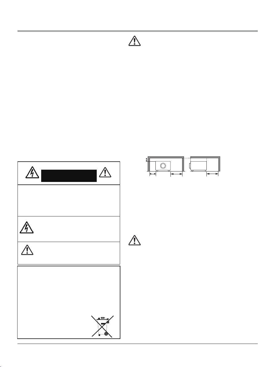
- Leave an appropriate space from the top,
sides, and back of the shell in order to
ventilate and cool down the projector. The
gures below indicate the minimum distance
to be left. It must be satised if the projector is
placed in sealed environment like a cabinet.
SIDE and TOP
REAR
- Do not cover the vent of the projector. Poor
radiation may shorten the service life or even
cause dangers.
- Remove the AC power plug if the projector
is not to be used for a long time.
- Do not project the same image for a long time;
otherwise, a residual image may appear on
the LCD panel due to its characteristic.
Caution
Do not set the projector in greasy, wet, or smoky
conditions such as in a kitchen, to prevent a
malfunction or accident. If the projector comes
in contact with oil or chemicals, it may become
deteriorated.
Read and keep this manual for future reference.
The mains plug/appliance coupler is used as
disconnect device, the disconnect device shall
remain readily operable.
4
Page 5
All the safety and operating instructions should be
read before the product is operated.
Read all of the instructions given here and retain them
for later use. Unplug this projector from AC power
supply before cleaning. Do not use liquid or aerosol
cleaners.Use a damp cloth for cleaning.
Follow all warnings and instructions marked on the
projector.
For added protection to the projector during a lightning
storm, or when it is left unattended and unused for
long periods of time, unplug it from the wall outlet.
This will prevent damage due to lightning and power
line surges.
Do not expose this unit to rain or use near water... for
example, in a wet basement, near a swimming pool,
etc...
Do not use attachments not recommended by the
manufacturer as they may cause hazards.
Do not place this projector on an unstable cart,
stand,or table. The projector may fall, causing serious
injury to a child or adult, and serious damage to the
projector.
Use only with a cart or stand recommended by the
manufacturer, or sold with the projector. Wall or
shelf mounting should follow the manufacturer’s
instructions, and should use a mounting kit approved
by the manufacturers.
An appliance and cart combination
should be moved with care. Quick
stops, excessive force, and uneven
surfaces may cause the appliance
and cart combination to overturn.
Slots and openings in the back and bottom of the
cabinet are provided for ventilation, to ensure reliable
operation of the equipment and to protect it from
overheating.
The openings should never be covered with cloth or
other materials, and the bottom opening should not be
blocked by placing the projector on a bed, sofa, rug,
or other similar surface. This projector should never
be placed near or over a radiator or heat register.
This projector should not be placed in a built- in
installation such as a book case unless proper
ventilation is provided.
Never push objects of any kind into this projector
through cabinet slots as they may touch dangerous
voltage points or short out parts that could result in a
re or electric shock. Never spill liquid of any kind on
the projector.
Safety Instruction
Do not install the projector near the ventilation duct of
air-conditioning equipment.
This projector should be operated only from the type
of power source indicated on the marking label. If you
are not sure of the type of power supplied, consult
your authorized dealer or local power company.
Do not overload wall outlets and extension cords as
this can result in re or electric shock. Do not allow
anything to rest on the power cord. Do not locate this
projector where the cord may be damaged by persons
walking on it.
Do not attempt to service this projector yourself as
opening or removing Covers may expose you to
dangerous voltage or other hazards. Refer all
servicing to qualied service personnel.
Unplug this projector from wall outlet and refer
servicing to qualied service personnel under the
following conditions:
a. When the power cord or plug is damaged or
frayed.
b. If liquid has been spilled into the projector.
c. If the projector has been exposed to rain or water.
d. If the projector does not operate normally by
following the operating instructions. Adjust only
those controls that are covered by the operating
instructions as improper adjustment of other
controls may result in damage and will often
require extensive work by a qualied technician to
restore the projector to normal operation.
e. If the projector has been dropped or the cabinet
has been damaged.
f. When the projector exhibits a distinct change in
performance, this indicates a need for service.
When replacement parts are required, be sure the
service technician has used replacement parts
specied by the manufacturer that have the same
characteristics as the original part. Unauthorized
substitutions may result in re, electric shock, or injury
to persons.
Upon completion of any service or repairs to this
projector, ask the service technician to perform routine
safety checks to determine that the projector is in safe
operating condition.
Information for users in the European Union
This is a device to project images onto a screen,etc., and is
not intended for use as indoor lighting in a domestic environment. Directive 2009/125/EC.
NOTE FOR CUSTOMERS IN THE US
Hg LAMP(S) INSIDE THIS PRODUCT CONTAIN
MERCURY AND MUST BE RECYCLED OR DISPOSED OF
ACCORDING TO LOCAL STATE OR FEDERAL LAWS.
5
Page 6
10
10
Safety Instruction
Air circulation
Vents in the cabinet are provided for ventilation.
To ensure reliable operation of the product and
to protect it from overheating, these openings
must not be blocked or covered.
Caution
Hot air is exhausted from the exhaust vent.
When using or installing the projector, the
following precautions should be taken.
- Do not put any ammable objects or spray
can near the projector. Hot air is exhausted
from the air vents.
- Keep the exhaust vent at least 1 meter away
from any objects.
- Do not touch a peripheral part of the exhaust
vent, especially screws and metallic part. This
area will become hot while the projector is
being used.
- Do not put anything on the projector. Objects
put on the cabinet will not only get damaged
but also may cause re hazard by heat.
Cooling fans are provided to cool down the
projector.
The fan’s running speed is changed according
to the temperature inside the projector.
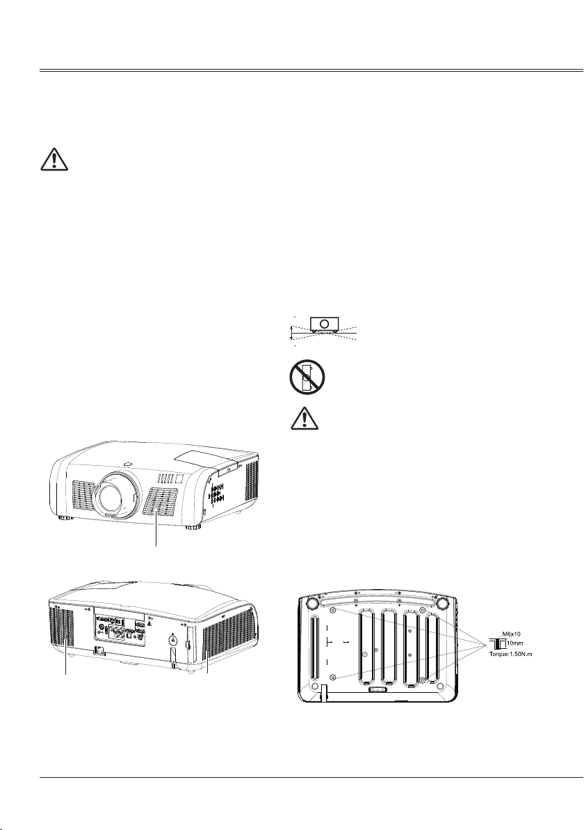
Air Intake Vent
Installing the projector properly
Be sure to use the projector properly in the
specied position. Improper positioning may
reduce the lamp lifetime, and even cause
grave accidents or a re hazard. The projector
can project images upwards, downwards or
slantwise in the direction vertical to a horizontal
surface. When slantwise installing the projector
downwards, make sure its bottom upturned.
√ Note: To turn over an image, please set the
function of Ceiling On.
Notes on Projector Positioning During
installation, avoid the project positioning
manners as described below.
Do not roll the projector over 10
degrees from side to side.
Do not put the projector on either
side to project an image.
Caution in ceiling installation the projector
- Only qualied personal is authorized for ceiling
installation.
- We are not responsible for the hurt and
damage caused by ceiling bracket that
purchased from unauthorized dealer even in
warranty period.
- Remove the ceiling bracket immediately while
not use.
- While installing, torque screwdriver is suggested,
don't use electric or impact-type screwdriver.
Exhaust Vent
6
Air Intake Vent
Page 7
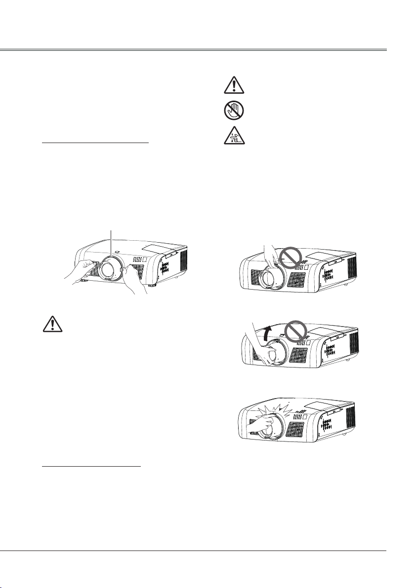
Moving the projector
When moving the projector, cover the lens
cap and retract the adjustable feet to prevent
damage to the lens and cabinet. Put it into
a carton with the lens facing upwards if the
projector is not in use for a long period.
Notes on Lens Protective Ring
Before operating the projector, remove the lens
protective ring. In case of transportation, press
LENS SHIFT button on the side control or on
the remote control for over 5 seconds to let the
lens back to its central position and put on the
lens protective ring to protect the lens.
Lens Protective Ring
Caution in moving or transporting the
projector
– Do not drop or bump the projector, otherwise
damages or malfunctions may result.
– When carrying the projector, use a suitable
carrying case.
– Do not transport the projector by courier or
any other transport service in an unsuitable
transport case. This may cause damage
to the projector. For information about
transporting the projector by courier or any
other transport service, consult your dealer.
– Do not put the projector in a case before it is
cooled enough.
Safety Guide
Note:
The lens of the projector is electric.
When operating the projector, pay
attention to the following conditions.
When the lens is rotating, do not
touch it, otherwise your ngers may
get hurt.
People who are not familiar with the
projector must not touch the lens.
Do not hold the lens and the peripheral part.
Notes on Projector Handling
When lifting or moving the projector, do not
hold the lens and the peripheral part to prevent
damage on the lens or projector.
Be careful in handling the projector. Do not
drop or bump it to avoid strong force, or place
other objects on the cabinet.
7
Page 8
Compliance
ASA
FCC Caution
Note: This equipment has been tested and found to comply with the limits for a Class B digital device,
pursuant to Part 15 of the FCC Rules. These limits are designed to provide reasonable protection against
harmful interference in a residential installation. This equipment generates, uses, and can radiate radio
frequency energy, and if not installed and used in accordance with the instructions, may cause harmful
interference to radio communications. However, there is no guarantee that interference will not occur in a
particular installation. If this equipment does cause harmful interference to radio or television reception,
which can be determined by turning the equipment off and on, the user is encouraged to try to correct the
interference by one or more of the following measures:
– Reorient or relocate the receiving antenna.
– Increase the separation between the equipment and receiver.
– Connect the equipment into an outlet on a circuit different from that to which the receiver is connected.
– Consult the dealer or an experienced radio/TV technician for help.
Use of shielded cable is required to comply with class B limits in Subpart B of Part 15 of FCC Rules.
Do not make any changes or modifications to the equipment unless otherwise specified in the
instructions. If such changes or modications should be made, you could be required to stop operation of
the equipment.
Model Number : LC-XN200, LC-WXN200,LC-XN200L,LC-WXN200L
Trade Name : EIKI
Responsible party : EIKI International, Inc.
Address : 30251 Esperanza Rancho Santa Margarita CA 92688-2132
Telephone No. : 800-242-3454 (949-457-0200)
AC Power Cord Requirement
The AC Power Cord supplied with this projector meets the requirement for use in the country you purchased it.
AC Power Cord for the United States and Canada:
AC Power Cord used in the United States and Canada is listed by the Underwriters Laboratories (UL)
and certified by the Canadian Standard Association (CSA).
AC Power Cord has a grounding-type AC line plug. This is a safety feature to be sure that the plug will fit
into the power outlet. Do not try to defeat this safety feature. Should you be unable to insert the plug into
the outlet, contact your electrician.
AC Power Cord for the United Kingdom:
This cord is already fitted with a moulded plug incorporating a fuse, the value of which is indicated on the
pin face of the plug. Should the fuse need to be replaced, an ASTA approved BS 1362 fuse must be
used of the same rating, marked thus
cover omitted. If a replacement fuse cover is required, ensure it is of the same colour as that visible on
the pin face of the plug (i.e. red or orange). Fuse covers are available from the Parts Department
indicated in your User Instructions.
If the plug supplied is not suitable for your socket outlet, it should be cut off and destroyed.
The end of the flexible cord should be suitably prepared and the correct plug fitted.
WARNING : A PLUG WITH BARED FLEXIBLE CORD IS HAZARDOUS IF ENGAGED IN A LIVE
SOCKET OUTLET.
The Wires in this mains lead are coloured in accordance with the following code:
Green-and-yellow ...... . . Earth
Blue ................. Neutral
Brown ............... Live
As the colours of the wires in the mains lead of this apparatus may not correspond with the coloured
markings identifying the terminals in your plug proceed as follows:
The wire which is coloured green-and-yellow must be connected to the terminal in the plug which is
marked by the letter E or by the safety earth symbol
The wire which is coloured blue must be connected to the terminal which is marked with the letter N or
coloured black.
The wire which is coloured brown must be connected to the terminal which is marked with the letter L or
coloured red.
WARNING: THIS APPARATUS MUST BE EARTHED.
. If the fuse cover is detachable, never use the plug with the
or coloured green or green-and-yellow.
THE SOCKET-OUTLET SHOULD BE INSTALLED NEAR THE EQUIPMENT AND EASILY ACCESSIBLE.
8
Page 9
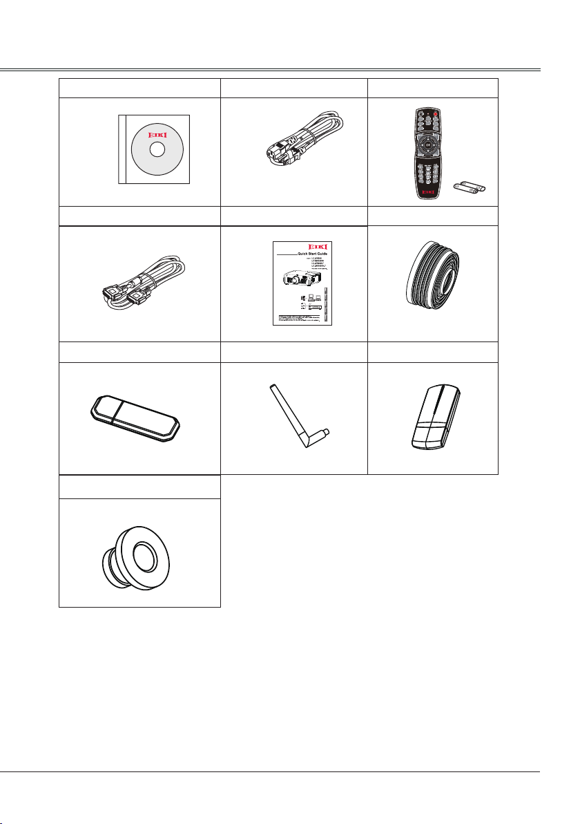
Owner's Manual(CD) AC Power cord
US Type x1
Euro Type x1
VGA cable Quick start guide Rubber Cap
WiFi Dongle Zigbee Antenna Zigbee Dongle
Remote control with batteries
(AA or LR6)
Accessories
Rubber gasket
9
Page 10
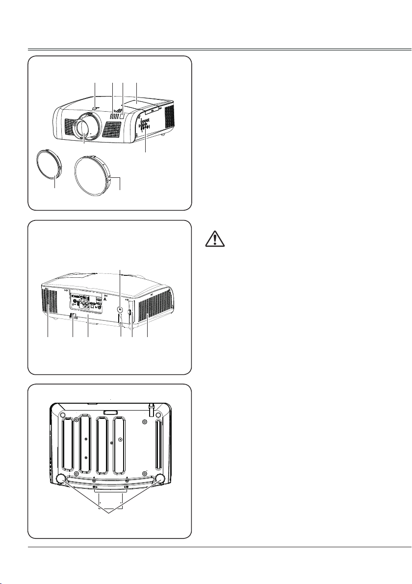
Part names and functions
Front
Back
Lens release button
① ②③④ ⑤
⑥
⑧
⑫
⑦
⑪
⑮
⑭⑩⑨
⑬
①
Remote control receiver
②
Control panel
③
Indicators
④
Lamp cover
⑤
Projection lens
⑥
Dust cap
⑦
(Prevent the internal element from dust when
projector lens is not installed)
Lens cover
⑧
Exhaust vent
⑨
Note:
Hot air is exhausted from the exhaust vent. Do
not put heat-sensitive objects near this side.
Rear terminals
⑩
Anti-theft slot
⑪
Power cord connector
⑫
Filter
⑬
Air intake vent
⑭
Anti-theft bar
⑮
Bottom
10
⑯
Adjustable feet
⑯
Page 11
Part names and functions
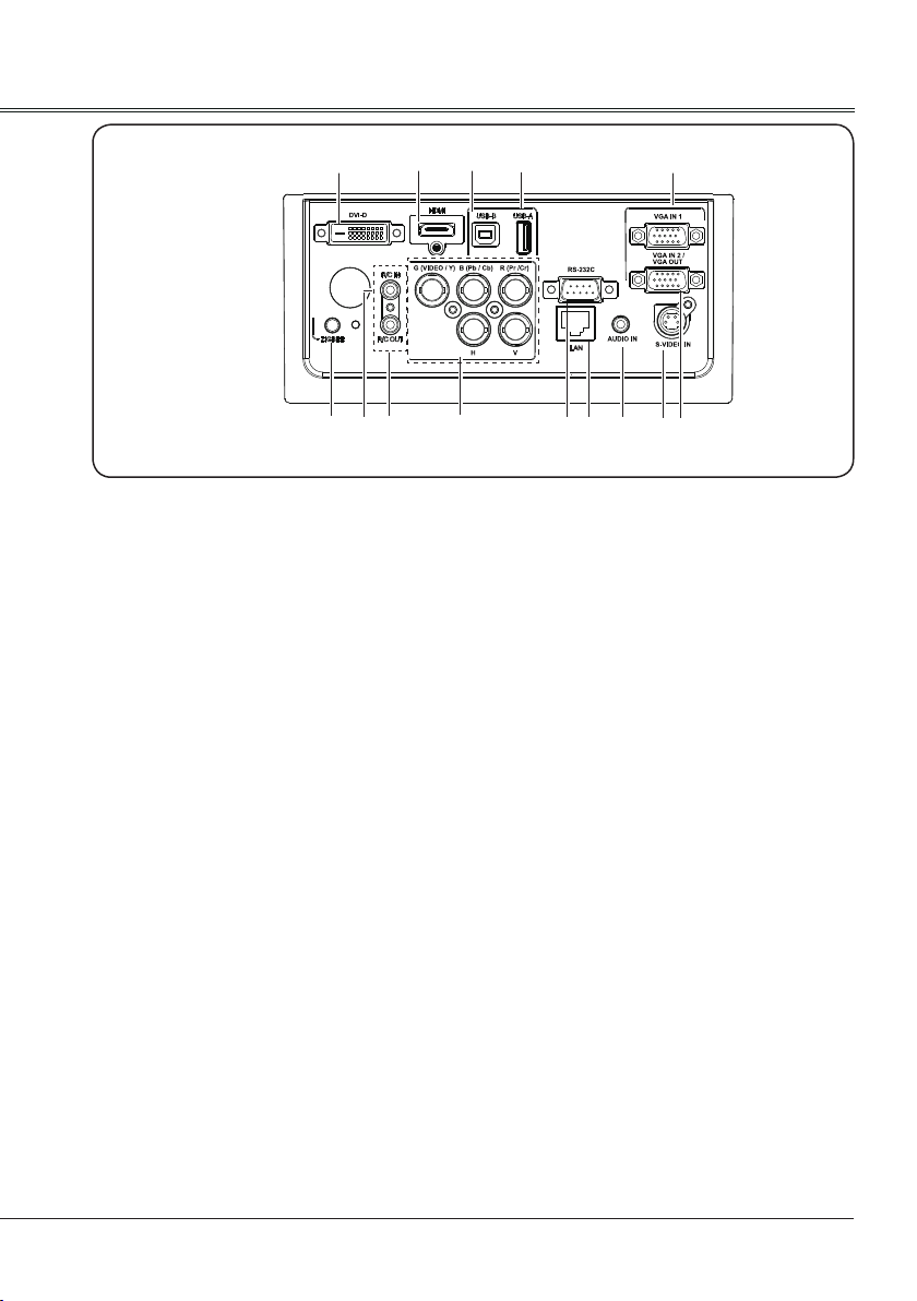
Rear Terminals
① ② ③ ④
⑭
DVI-D
①
Connect the DVI digital output signal to this
terminal.
HDMI
②
Connect digital output signal from HDMI to this
terminal.
USB-B
③
Connect one end of B type USB cable to this
terminal and the other end to a computer to
project the computer screen.
USB-A
④
- Connect A type USB device (e.g. USB ash
drive) to this terminal (Support FAT File System).
- WiFi dongle to this terminal.
LAN
⑤
When using wired network to control and operate
the projector, connect the wired network cable to
this terminal.
VGA IN 1
⑥
Connect output from the source signal from
computer to this terminal.
VGA IN 2/VGA OUT
⑦
- Connect output signal from computer to this
terminal.
- Output the signal from ⑥ to other monitor.
S-VIDEO IN
⑧
Connect S-Video signal to this jack.
AUDIO IN
⑨
Connect the audio signal output to this jack.
⑥
⑤
⑩⑪⑫⑬
RS-232C
⑩
When using RS-232C serial commands to control
or operate the projector, connect the serial cable
to this terminal.
Set "Standby mode" in "Setting" menu as "Normal"
and set "Zigbee mode" in "Zigbee setting" in
"Network" menu as "OFF".
R(Pr/Cr)/G(VIDEO/Y)/B(Pb/Cb)/H/V
⑪
- Connect RGBHV (5BNC) signal to R, G, B, H
and V jacks respectively.
- Connect composite video signal from video
device to G(VIDEO/Y) terminal.
- Connect component signal to Y,Pb/Cb,Pr/Cr.
R/C OUT
⑫
When using this output port, the output is
completed by connecting the wired remote control
cable to the wired remote control input port of
another device.
R/C IN
⑬
When using wired remote control, connect the
wired remote control cable to this port.
The wireless remote control is disable after
inserting the wired remote control cable to either
the remote control or R/C in terminal.
ZIGBEE
⑭
Transmit wireless short-distance signal.
Please insert the rubber gasket (supplied) into
this jack to prevent static electricity when the
ZIGBEE function is not used. When using
the ZIGBEE function, Please insert the Zigbee
antenna.
⑧⑨
⑦
11
Page 12
Part names and functions
AUTO SETUP
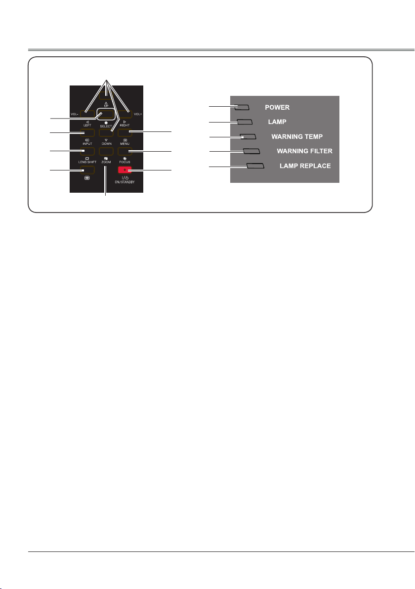
Side control panel
①
②
③
④
⑤
⑥
UP/DOWN/LEFT(VOL-)/RIGHT(VOL+)
①
- Select item or adjust data in screen menu.
- Select the image display area in digital
zoom + mode.
- Adjust the volume.
SELECT
②
Enter screen menu or execute selected
items.
INPUT
③
Select an input source.
LENS SHIFT
④
Enter lens shift mode.
AUTO SETUP
⑤
Perform various settings congured
automatically.
ZOOM
⑥
Enter zoom adjust mode.
⑦
⑧
⑨
Indicators
⑩
⑪
⑫
⑬
⑭
ON/STAND-BY
⑨
Turn on or off the projector.
POWER
⑩
- Lights red when the projector is in stand by mode.
- Lights green during operations.
- Flashes green when the projector is in
power management mode (stand-by).
LAMP
⑪
Lights green during operations.
WARNING TEMP
⑫
Flashes red when the internal temperature
of the projector is beyond the operating
temperature range.(Page 58,66)
WARNING FILTER
⑬
Lights red when the service life of the lter
is over. You should replace it with a new
one immediately.(Page 59)
MENU
⑦
Open or close the screen menu.
FOCUS
⑧
Enter focus adjust mode.
12
LAMP REPLACE
⑭
Lights yellow when the service life of the
lamp is over. You should clean it with a new
one immediately.(Page 61)
Page 13
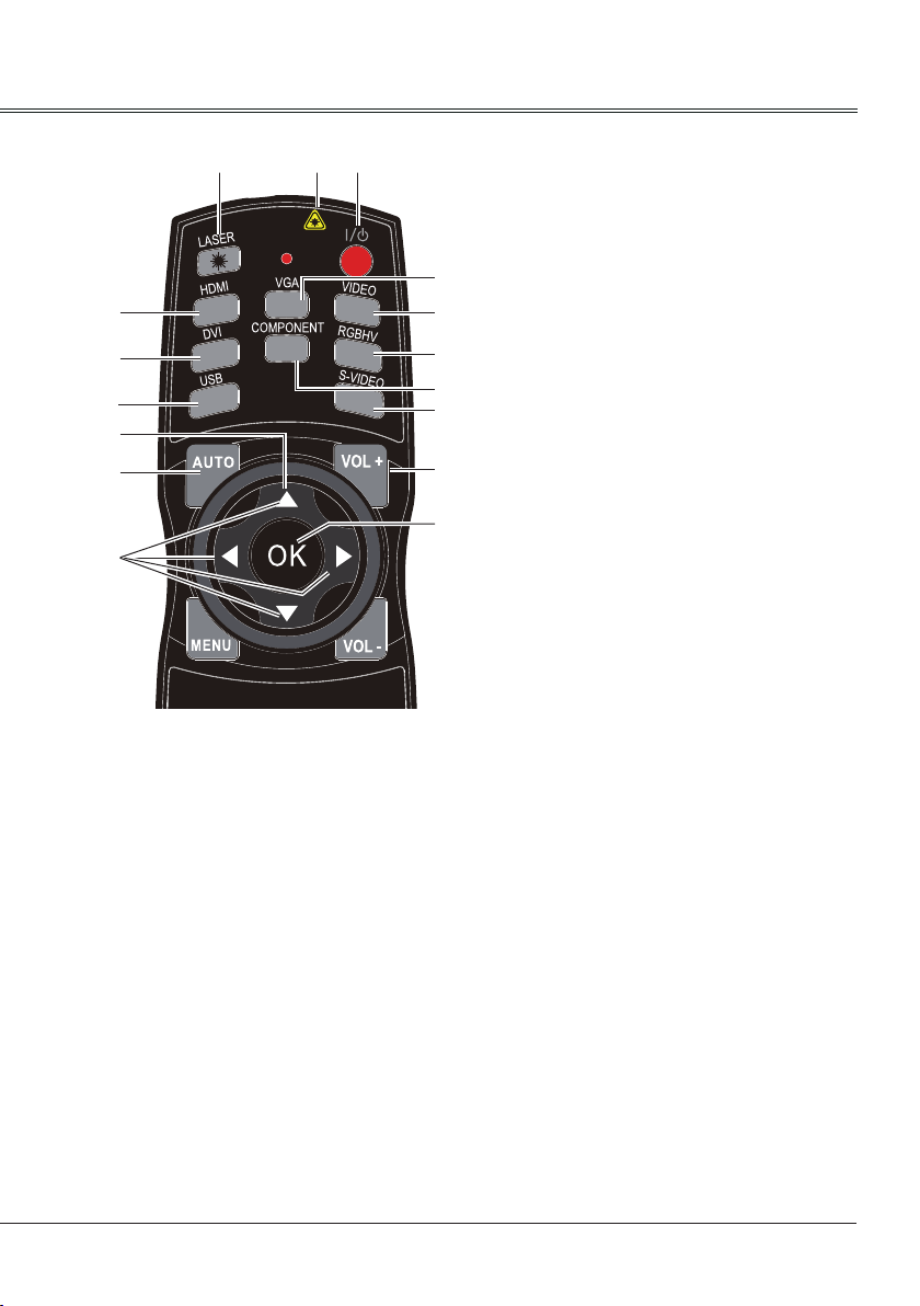
Remote Control
②
③
④
⑨
⑪
⑫
⑪
*Laser Transmitting Window:
Laser beam will emit from this window. While
pressing LASER button during the projection
to use the remote control as a laser pointer.
Do not stare directly at the laser transmitting
window or aim the window at human body, to
avoid any physical injury.
POWER
①
Turn on or turn off the projector.
LASER
②
Press this button during projection, the
remote control can be used as a laser
pointer.
HDMI
③
Select “HDMI” as input source.
①
*
⑤
⑥
⑦
⑧
⑩
⑭
⑬
Part names and functions
DVI
④
Select “DVI” as input source.
VGA
⑤
Select “VGA IN 1” or “VGA IN 2” as input
source.
-VGA IN 2 can not be selected
when using the VGA IN 2/ VGA OUT
terminal as MONITOR OUT output.”
- Press VGA button directly to switch VGA
IN 1 or VGA IN 2.
VIDEO
⑥
Select “Video” as input source.
RGBHV
⑦
Select “RGBHV” as input source.
COMPONENT
⑧
Select “Component” as input source.
USB
⑨
Select Image Viewer as input source.
Press this button again to select USB
Autorun.
Every time pressing this button, input source
becomes as follows:
Image Viewer
- USB Autorun
- Image Viewer
S-VIDEO
⑩
Select “S-video” as input source.
⑪
- Select item or adjust data in screen menu.
- Select the image display area in digital
zoom + mode.
AUTO
⑫
Enter auto setup adjust mode.
OK
⑬
Enter the menu or select an item in the
menu.
VOL+
⑭
Increase the volume level.
13
Page 14
Part names and functions
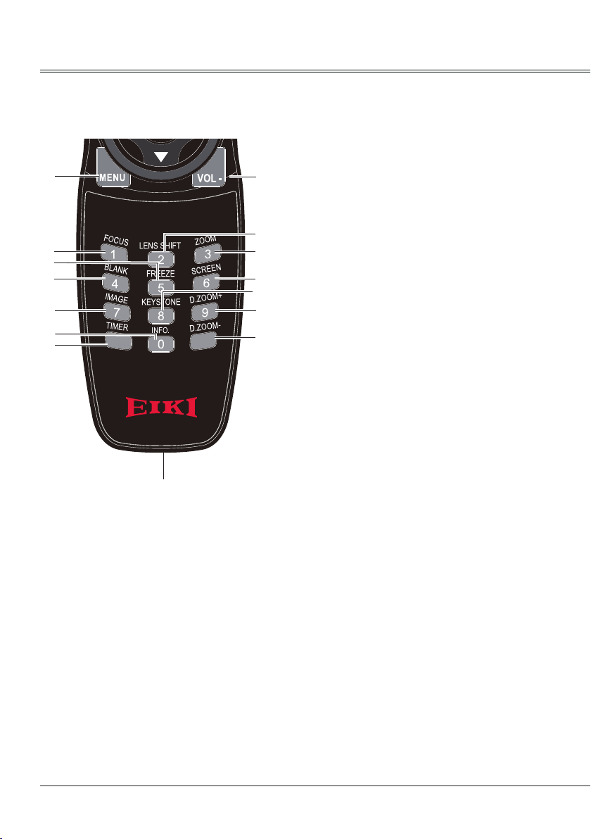
Remote Control
⑮
⑰
㉑
⑳
㉓
㉗
㉘
ZOOM
⑲
Enter image size adjust mode.
BLANK
⑳
⑯
Temporarily close the image on the screen.
FREEZE
㉑
Freeze the project image.
⑱
⑲
㉒
㉔
㉕
㉖
SCREEN
㉒
Select screen mode.
IMAGE
㉓
Select image mode.
KEYSTONE
㉔
Correct the H/V Keystone distortion.
Every time pressing this button,the mode
becomes as follows:
Keystone
- H/V Keystone
- Corner
D.ZOOM+
㉕
Select the digital zoom + mode.
㉙
MENU
⑮
Open or close the screen menu.
VOL-
⑯
Decrease the volume level.
FOCUS
⑰
Enter focus adjust mode.
LENS SHIFT
⑱
Enter lens shift mode.
(Press and hold LENS SHIFT button on
remote control for over 5 seconds to move
the lens back to central position).
14
D.ZOOM-
㉖
Select the digital zoom - mode.
INFO.
㉗
Display current status information of the
projector.
TIMER
㉘
Enable the timer function.
Wired remote control output port
㉙
Connect the wired remote control cable to
this port while operating the projector by
wired remote control.
Page 15
Part names and functions
5m
5m
Install remote control batteries
①
Open the battery
compartment lid.
To ensure safe operation, please observe the following precautions:
● Use two (2) AA or LR6 type batteries.
● Always replace batteries in sets.
● Do not use a new battery with a used battery.
● Avoid contact with water or liquid matter.
● Do not expose the remote control to moisture or heat.
● Do not drop the remote control.
● If the battery has leaked in the remote control, carefully wipe the case clean and
install new batteries.
● Risk of explosion if two batteries are replaced by an incorrect type.
● Dispose of used batteries according to the instructions on the battery or local
regulations or guides.
②
Install new batteries
into the compartment.
Two AA batteries
For correct polarity
(+ and –), be sure
battery terminals are
in contact with pins
in the compartment.
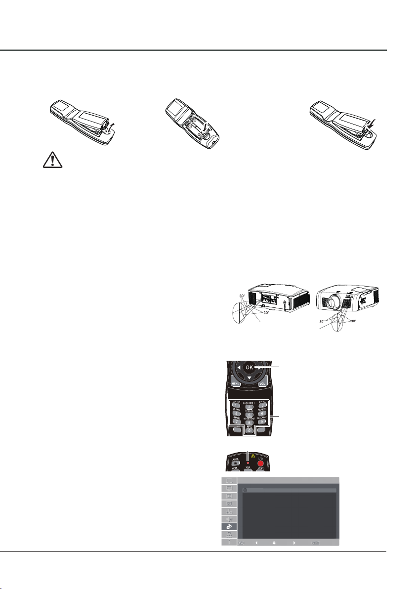
Remote Control Operating range
Point the remote control toward the projector
remote receiver (front and back) when pressing
any button.
The maximum operating range for the remote
control is about 5 meters and 60 degrees.
③
Replace the
compartment lid.
Remote Control Code
The ten different remote control codes (Code
0 - Code 9) are assigned to this projector.
Switching the remote control codes prevents
interference from other remote controls
when several projectors or video equipment
next to each other are operated at the same
time. Change the remote control code for the
projector first before changing that for the
remote control. See "Remote control" in the
Setting Menu on page 57.
Press and hold the OK and any number button
(0-9) for more than five seconds to switch
among Code 0 - Code 9.
The initial code is set to Code 0.
Remote control
LED indictaor
Code 0
Code 1
Code 2
Code 3
Code 4
Code 5
Code 6
Code 7
Code 8
Code 9
Setting
Remote Control
Exit MoveBack ---- Select
OK
Press and hold
the OK and any
number button
(0-9) for more
than five seconds
to switch among
Numbers
Code 0 - Code 9.
LED indictor on the
remote control will flash
twice after the code is
successfully set.
3/3
15
Page 16
Installation
Min.
300”
300”
200”
150”
100”
40”
3.45m(3.70m)
5.18m(5.50m)
6.91m(7.60m)
Max.
1.38m(1.50m)
10.36m(11.30m)
17.62m(19.10m)
(Diagonal:Inch)
(Center)
300”
200”
150”
100”
40”
300”
6.70m(7.50m)
3.40m(3.80m)
5.10m(5.60m)
1.30m(1.50m)
17.20m(19.20m)
10.10m(11.20m)
Min.
Max.
(Diagonal:Inch)
(Center)
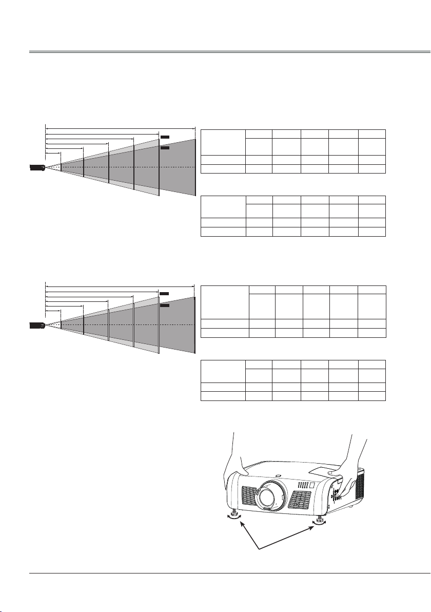
Positioning the projector
Note:
● The brightness in a room has a great inuence on image quality. It is recommended to limit the
ambient lighting in order to get the best image.
● All measurements are approximate and may vary from the actual sizes.
LC-XN200:
Note:
The data in "()" is the project distance for
16:9 aspect ratio.
4:3 :
Screen size
(WxH)mm
4:3 aspect ratio
Maximum 1.38m 3.45m 5.18m 6.91m 10.36m
Minimum 2.35m 5.87m 8.81m 11.74m 17.62m
40" 100" 150" 200" 300"
813x610 2032x1524
3048x2286
4064x3048 6096x4572
16:9 :
Screen size
(WxH)mm
16:9 aspect ratio
Maximum 1.50m 3.70m 5.50m 7.60m 11.30m
Minimum 2.50m 6.30m 9.50m 12.70m 19.10m
40" 100" 150" 200" 300"
3320x1867
885x498 2213x1245
4427x2490 6641x3735
LC-WXN200:
Note:
The data in "()" is the project distance for
16:9 aspect ratio.
Adjustable feet
The projection angle can be adjusted up to 5.0
degrees with the adjustable feet.
Rotate the adjustable feet to lift the projector
to a certain height. During lifting, rotate the two
feet clockwise.
To lower or retract the adjustable feet, rotate
the two feet counterclockwise.
Keystone distortion of projected images can
be corrected by auto settings, remote control
operation or menu operation.
16
16:10 :
Screen size
(WxH)mm
16:10 aspect
ratio
Maximum 1.30m 3.40m 5.10m 6.70m 10.10m
Minimum 2.20m 5.70m 8.50m 11.40m 17.20m
40" 100" 150" 200" 300"
861x538 2154x1346
3231x2019
4307x2692 6461x4038
16:9 :
Screen size
(WxH)mm
16:9 aspect ratio
Maximum 1.50m 3.80m 5.60m 7.50m 11.20m
Minimum 2.60m 6.40m 9.60m 12.80m 19.20m
40" 100" 150" 200" 300"
3320x1867
885x498 2213x1245
4427x2490 6641x3735
Adjustable feet
Page 17
Installation
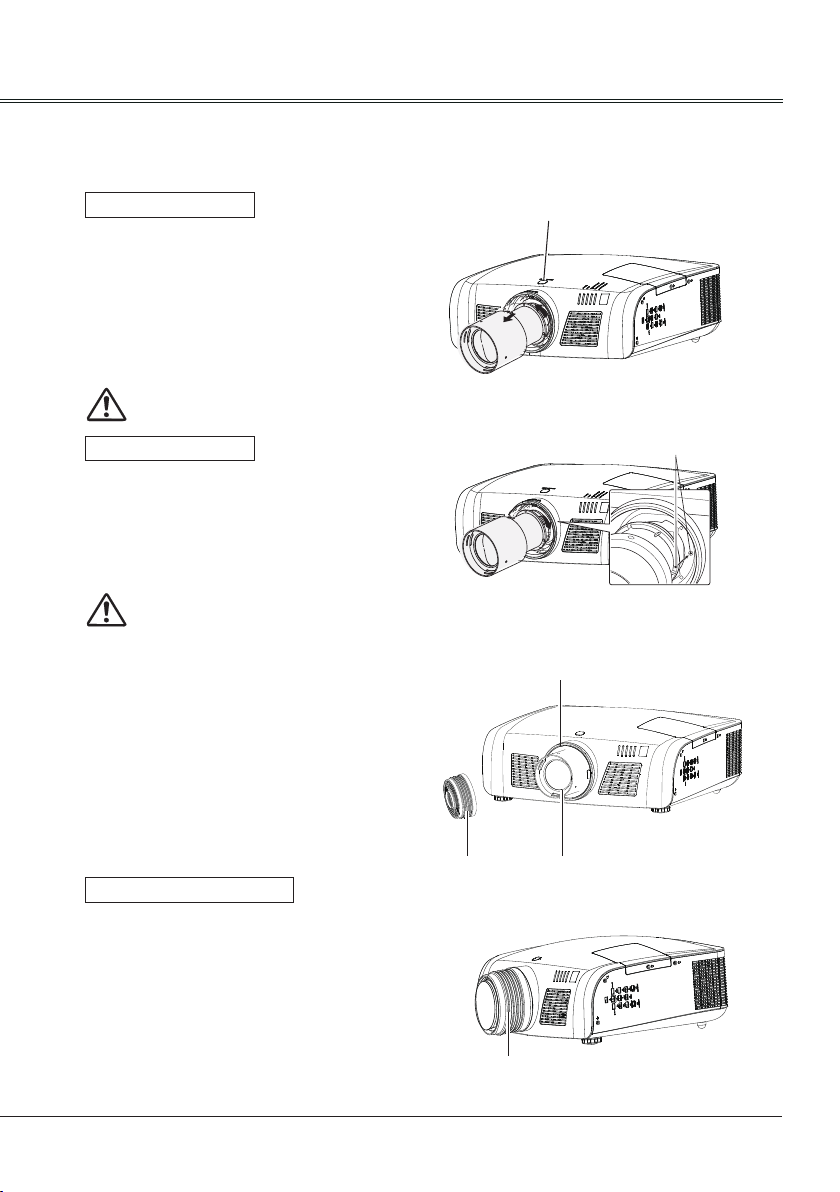
Lens installation
Follow the instructions below to install the lens upon replacing or using the optional lens. For the
specication of optional lens, contact your dealer.
Removing the lens
1 Shift the lens to the center with the lens shift
function.(Page 28)
2 Turn off the projector, and unplug the AC
power cord.
3 Press and hold the lens release button
on the top cabinet,rotate the lens
counterclockwise until the lens cannot be
rotated. Draw it out slowly from the projector.
Caution
Do not drop the lens when handling.
Installing the lens
1 Remove the lens protective cover.
2 Align the red point on the lens with that on
the projector to install the lens.
3 Rotate the lens clockwise slowly until it
clicks.Make sure that the lens is installed
completely in the projector.
Caution
While installing the lens, do not hold the
release button.
Notes on lens installation:
● Do not touch or remove any part except lens
and its relative part. This may cause a
malfunction, electric shock, re or other
hazards.
● Make sure the mode of the lens is
compatible with your projector before
installing or replacing the lens.
● For information about the lens and its
installation, contact the local dealer.
Installing the rubber cap
When using the projector in dusty weather or
environment, please install the rubber cap to
protect the projector lens or optical components
from dust accumulation, otherwise, the quality
of the projected image will be affected.
The rubber cap is made of the elastic material.
While installing, put the large opening end
into the projector lens on the decoration ring
rst, then open the small opening end to avoid
blocked the projection image.
Lens release button
Rubber cap
Rubber cap
Red point
Decorative ring
Lens
17
Page 18
Installation
b
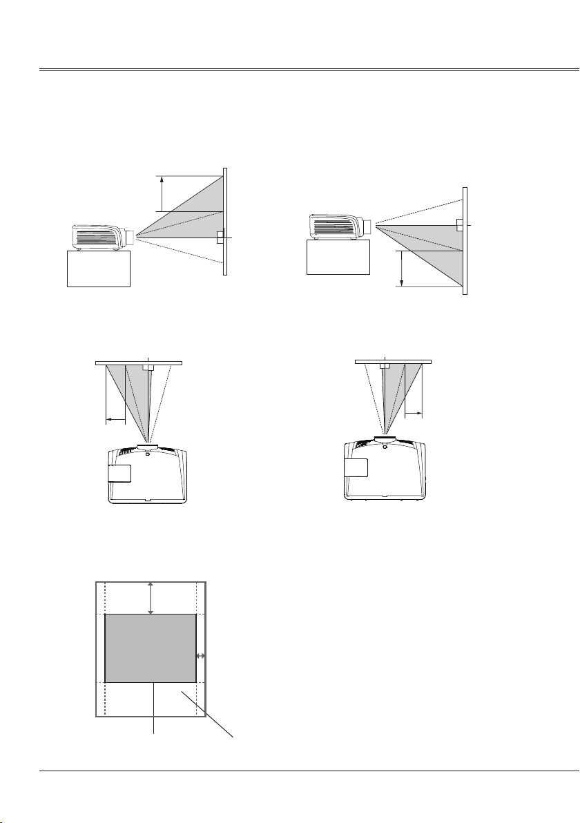
Lens shift adjustment
Projection lens can be moved from side to side and up to down.
This function makes the positioning of images easy on the screen.
The display position can be shifted upward up
to 50% elevation of the display.
The display position can be shifted downward
up to 50% elevation of the display.
a
a
When the lens is shifted to top.
The display position can be shifted to the left
up to 10% width of the display.
b
When the lens is shifted to leftmost. When the lens is shifted to rightmost.
When the lens is shifted to bottom.
The display position can be shifted to the right
up to 10% width of the display.
50% elevation of the display and 10% width of
the display.
a
b
When the lens is
shifted to the center.
Shifting range
18
Page 19
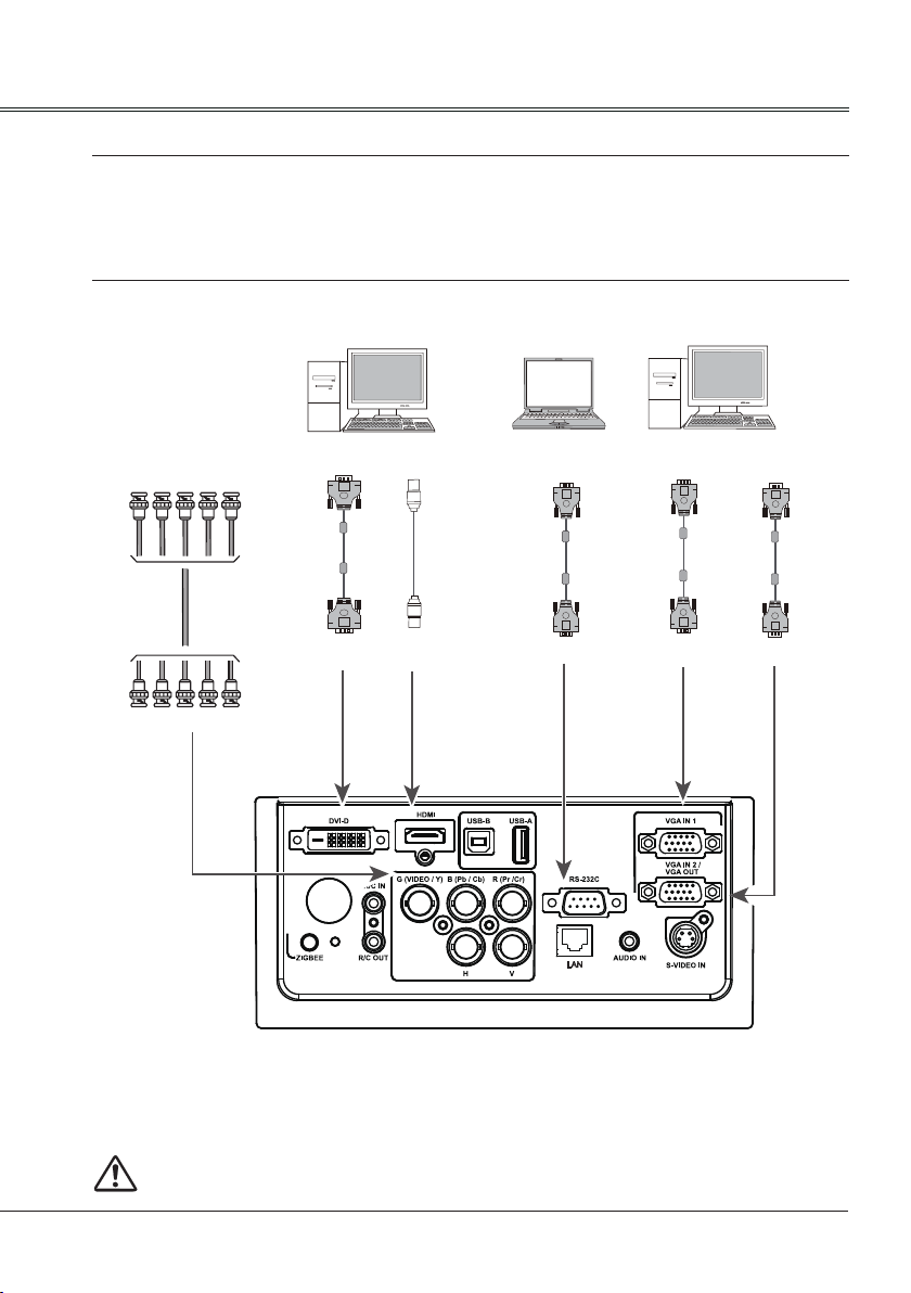
Connecting to computer(Digital and analog RGB)
Cables used for connection:
● VGA cable ● Serial crossover cable*
● DVI cable* ● BNC cable*
● HDMI cable*
(*=Cables not supplied with the projector)
Installation
RGBHV signal
BNC
cable
RGBHV input
DVI output
DVI
digital
cable
HDMI
cable
DVI input HDMI input
HDMI output
RS232 output
Serial
crossover
cable
RS232 input
VGA output
VGA
cable
VGA input
VGA input/output
VGA
cable
VGA output/input
Unplug the power cords of both the projector and external equipment from the AC outlet
before connecting the cables.
19
Page 20
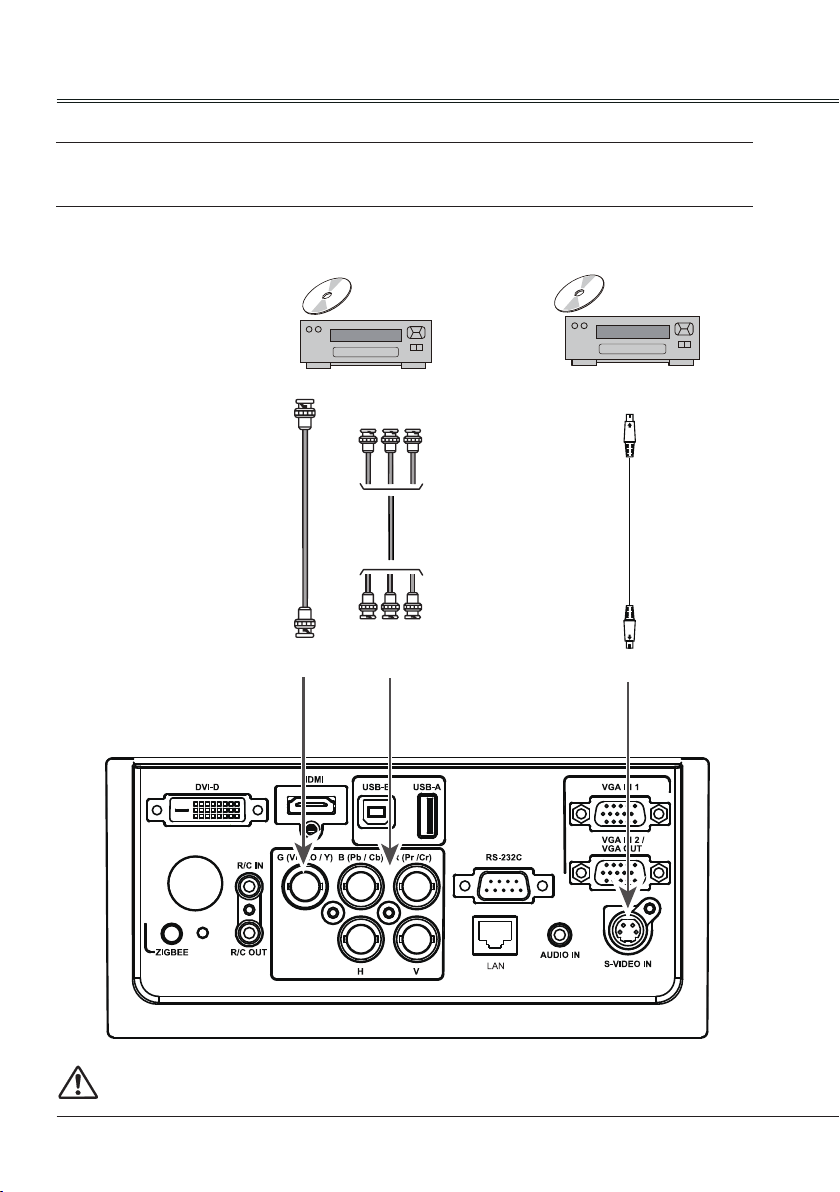
Installation
Connecting to video equipment (Video, S-Video)
Cables used for connection
● Video cable * ● RCA cable * ● BNC cable *
(*=Cables not supplied with the projector)
Composite video output
BNC
cable
Composite video input
Component video output
RCA
cable
Component video input
S-video output
S-Video
cable
S-Video input
Unplug the power cords of both the projector and external equipment from the AC outlet
before connecting the cables.
20
Page 21
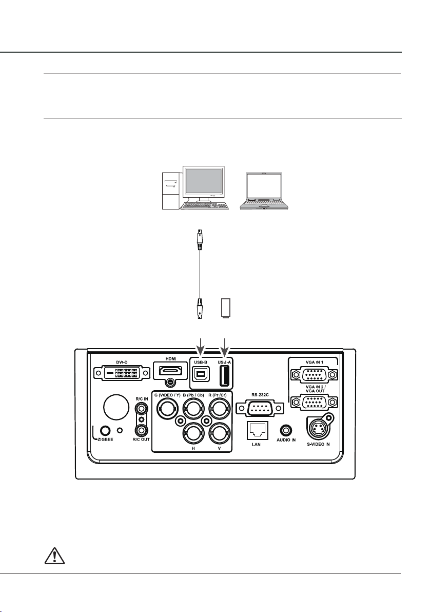
Connecting to USB device (USB-A, USB-B)
Connect the wireless network adapter to USB –A port
Cables used for connection
● USB-A cable * ● USB-B cable *
(*=Cables not supplied with the projector)
USB-A
output
USB-B
cable
USB-A device or
wireless network adapter
Installation
USB-B
input
Unplug the power cords of both the projector and external equipment from the AC outlet
before connecting the cables.
21
Page 22
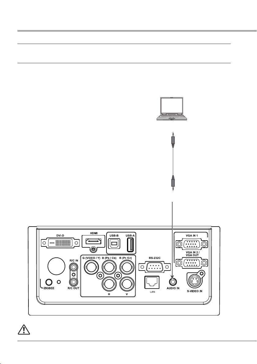
Installation
Connecting to audio equipment
Cables used for connection:
● Audio cable*
(*=Cables are not supplied with the projector)
Audio output
Audio cable
(stereo)
Audio input
Unplug the power cords of both the projector and external equipment from the AC outlet
before connecting the cables.
22
Page 23
Connecting the AC power cord
This projector uses nominal input voltages of
100–240V AC and it automatically applies to
different input voltages. It is designed to work
with a single-phase power system having a
grounded neutral conductor.
To reduce the risk of electrical shock, do not
plug into any other type of power system. If
you are not sure of the type of power being
supplied, consult your authorized dealer or
service station. Connect the projector with all
peripheral equipment before turning it on.
Installation
Note:
The AC outlet should be near this equipment
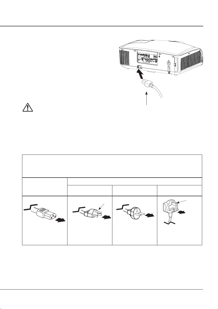
Connect the AC power cord
(supplied) to the projector.
and must be easily accessible.
Note:
For safety, unplug the AC power cord when the projector is not in use. When the projector is
connected to an outlet with AC power cord, it is in stand-by mode and consumes a little electric
power.
Note on the power cord
AC power cord must meet the requirements of the country where you use the projector. Conrm the AC
plug type with the chart below and proper AC power cord must be used. If the supplied AC power cord
does not match, contact your sales dealer.
AC outlet side
Projector side
To power cord
connector on your
projector.
For the U.S.A. and
Canada
Ground
To the AC outlet. To the AC outlet.
For Continental
Europe
For the U.K.
Ground
To the AC outlet.
√ Note:
Using incorrect power cord may inuence the product performance, or even cause hazards like an
electric shock or re. To ensure the product performance and security, please apply the cable of the
same model with the original one.
23
Page 24
Basic operation
Turn on the projector
1.Complete peripheral connections (with a
computer, VCR,etc.) before turning on the
projector.
2. Connect the projector’s AC power cord into
AC outlet. The POWER indicator turns red.
3. Press the POWER button on side control or
on the remote control. The POWER indicator
becomes green and the cooling fans start to
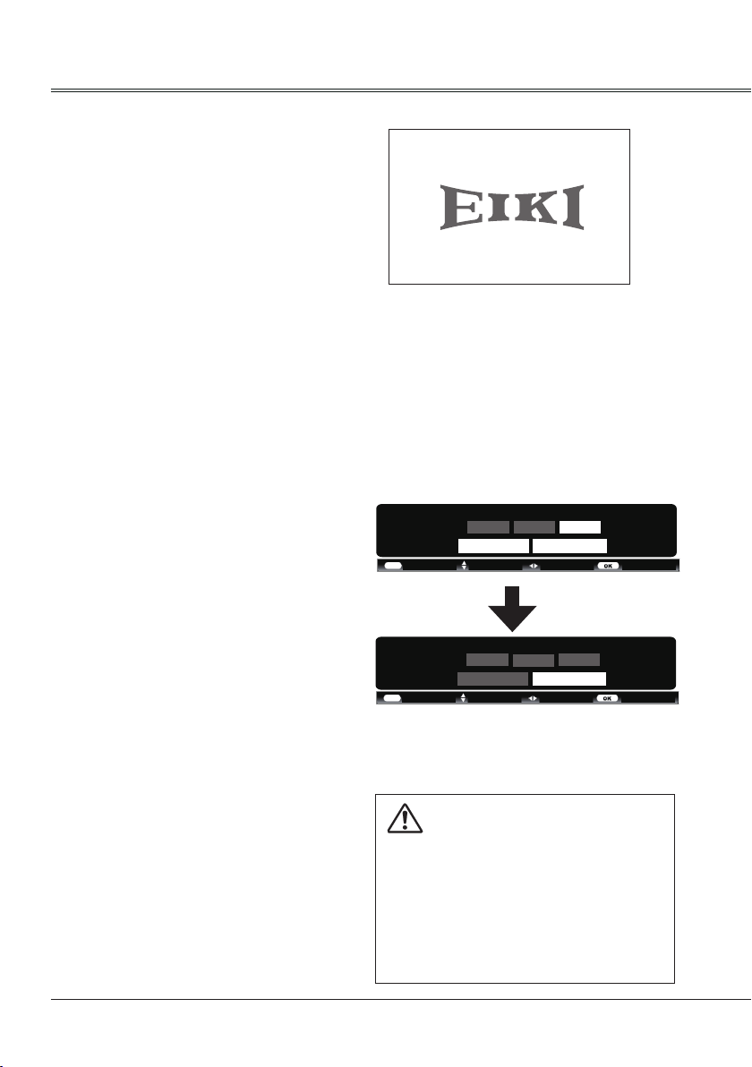
work. The preparation display appears on
the screen and the countdown starts.
4. If the projector is locked with a PIN code, a
PIN code input dialog box appears. Enter
the PIN code as instructed below.
Note:
● When the logo select is set to be "Off" the
logo will not be displayed on the screen.(Page51)
● When the Display function is set to be "Off" ,
the logo and countdown will not be displayed
on the screen.(Page50)
● During the countdown period, all operations
are invalid except shutdown.
Enter a PIN code
Select a number by pressing button, and
then press button to fix the number and
move the cursor. The number changes to “*”. If
you fixed an incorrect number, move the cursor
to the number you want to correct by pressing
button, and then select the correct number
by pressing button.
Repeat this step to complete entering a threedigit number.
After entering the three-digit number, move the
cursor to “Set”, then you can start to operate
the projector.
If you entered an incorrect PIN code, the “PIN
code” and the number (***) turn red. Enter the
correct PIN code all over again.
What is PIN code?
PIN (Personal Identification Number) code is a
security code that allows the person who knows
it to operate the projector. Setting the PIN code
can prevent unauthorized use of the projector.
A PIN code consists of a three-digit number.
Refer to the PIN code lock function in the
Advanced setting menu on pages 55 for PIN
code lock operation of the projector.
16
Start-up display
PIN code
* 0
Set Clear
CANCEL
CANCEL
- - - - Move Select
Adjust- - - - Move - - - -
PIN code
*
* *
Set Clear
- - - -- - - -
*
Move the cursor to Set, and press SELECT.
Caution on handling the PIN code
If you forget your PIN code, the
projector can no longer be started.
Take a special care in setting a
new PIN code. Write down the
number in a column on page 74 of
this manual and keep it properly.
Should the PIN code be missing
or forgotten, consult your dealer
or service center.
24
Page 25
Turn off the projector
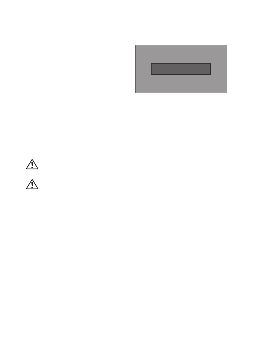
1. Press the POWER button on side control
or on the remote control, and “Power off?”
appears on the screen.
Basic operation
2. Then, press the POWER button again in 4
seconds. The POWER indicator starts to
ash red, and the cooling fans keep running
(You can select the level of fans’ quietness
and running speed.). Now you can unplug
the AC power cord after the fans stop
running, otherwise, the service life of the
projector will be affected or the projector will
can not be turned on or turn on abnormal.
3 When the projector has cooled down enough
to be turned on again, the POWER indicator
stops ashing.
To maintain the lamp life, once you turn
the projector on, wait at least 5 minutes
before turning it off.
Do not operate the projector
continuously without reset.
Continuous use may result in shortening
the lamp life.Turn off the projector and
let it standby for about an hour in every
24 hours.
Power off ?
“Power off ? ” disappears after 4 seconds.
Note:
● When the On start function is “On” , this
projector is turned on automatically by
connecting the AC power cord to an AC outlet .
● The running speed of cooling fans is changed
according to the temperature inside the
projector.
● Do not put the projector in a case before it is
cooled enough.
● If the WARNING TEMP indicator flashes, see
“Warning Temp”.(page 58)
● While the POWER indicator is flashing, the
lamp is being cooled down and the projector
cannot be turned on. Wait until the POWER
indicator turns red to turn on the projector
again.
● The fan rotation will terminate directly if the
AC power cord is unplugged immediately after
the projector is turned off.
● The projector can be turned on after the
POWER indicator turns red. The waiting
time to restart will be shortened when the
normal power-off processing for fan cooling
is completed, comparing with the time the AC
power cord is immediately unplugged after the
power-off.
25
Page 26
Basic operation
AUTO SETUP
How to operate the on-screen menu
The projector can be adjusted or set via the
on-screen menu, each main menu can be
divided into several levels of submenus, and
submenus are also divided into several levels
of secondary submenus.
For each adjustment and setting procedure,
refer to the respective sections in this manual.
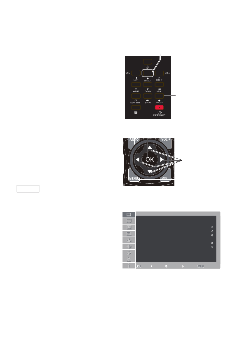
Menu
1 Press the MENU button on the side control or
the remote control to show the screen menu.
2 Press
menu and then press OK or
enter the submenu.
3 Press
and then press OK or
enter the submenu.
4 Press
switch among the items. Press the OK button
for corresponding operation and then
return to the submenu.
buttons to select an entry in the main
buttons to select your required item,
button to adjust settings or
button to
button to set or
Side control
Remote control
OK
Screen menu
Auto PC adj.
Fine sync
Total dots
Horizontal
Vertical
Clamp
Display area H
Display area V
Reset
Mode free
Store
Exit Move Next Next
SELECT
PC adjust
MENU
MENU
0
0
1
5 Press
button to return to the previous menu.
Press MENU on the remote control again to exit
the on screen menu.
26
Page 27
Basic operation
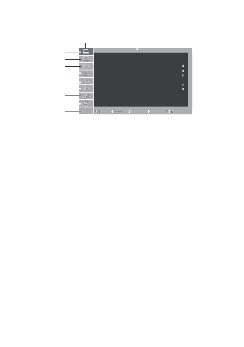
Menu bar
PC adjust menu
①
①
②
③
④
⑤
⑥
⑦
⑧
⑨
Main menu
Sub menu
Auto PC adj.
Fine sync
Total dots
Horizontal
Vertical
Clamp
Display area H
Display area V
Reset
Mode free
Store
Exit Move Next Next
PC adjust
0
0
1
Adjust computer parameters to match with VGA input signal format: Auto PC adj., Fine sync,
Total dots, Horizontal, Vertical, Clamp, Display area H, Display area V, Reset, Mode free,
Store.
Screen menu
②
If a computer is selected as a signal source, the following setup options for the image size are
available: Normal, Wide, True, Full, Custom or Digital zoom +/- .
If video equipment is selected as a signal source, the following setup options for the image size
are available: Normal, Wide or Custom (for XGA models) / Normal, Full, Wide or Custom(for
WXGA models).
Image select menu
③
The available image modes are: Dynamic, Normal, Cinema, Blackboard (green), Colorboard
or User Image.
Image adjust menu
④
If a computer is selected as a signal source, the following image adjusting options are available:
Contrast, Brightness, Color temp., White balance (R/G/B), Sharpness and Gamma.
If video equipment is selected as a signal source, the following image adjusting options are
available: Contrast, Brightness, Color, Tint, White balance (R/G/B), Sharpness, Gamma,
Noise reduction and Progressive.
Input menu
⑤
Select an input source from HDMI, DVI, VGA IN 1, VGA IN 2, Component, S-video, Video,
RGBHV, Network, Image Viewer, USB Autorun.
Sound menu
⑥
Adjust the volume level or mute the sound.
Setting menu
⑦
Congure operation settings of the projector.
Network menu
⑧
Access the network function.
Information menu
⑨
Display the system information of the projector.
27
Page 28
Basic operation
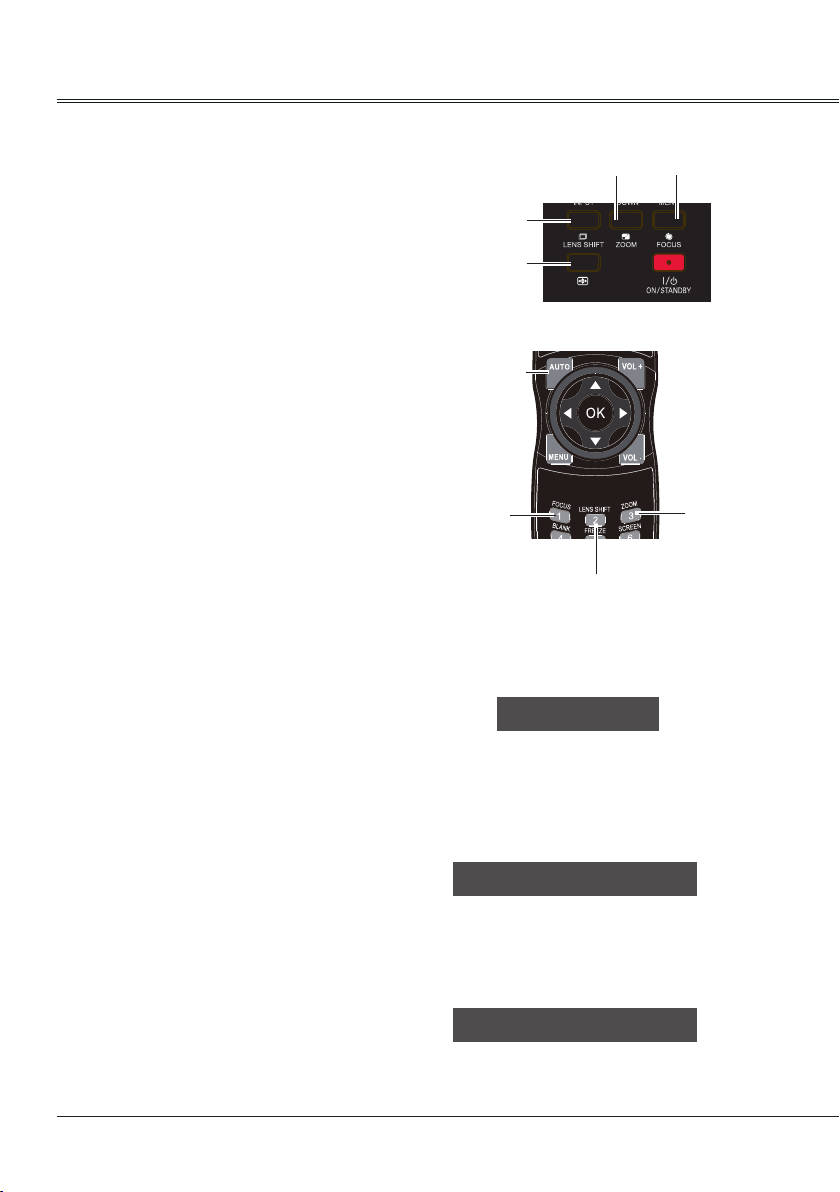
Auto setup
This function is available just by pressing
the AUTO SETUP button on the side control
or AUTO button on the remote control. The
system then automatically performs various
settings in the setup menu, including Input
search and Auto PC adjust.
Side control
LENS SHIFT
AUTO SETUP
AUTO SETUP
ZOOM
FOCUS
Lens shift adjustment
1. Perform the lens shift adjustment with LENS
SHIFT button on side control or on the
remote control.
2. Lens shift appears on the screen. Press
point
desired position without any image distortion.
The screen may deviate up-and-down from
the central axis of lens shift at most 50% top
and bottom or at most 10% left-and-right.
3. Press and hold LENS SHIFT button on side
control or remote control for over 5 seconds
to move the lens back to central position.
√ Note:
When the lens is not under shift adjustment,
the arrow displays in green.
When the lens is under shift adjustment, the
arrow turns yellow.
When the lens shift reaches its greatest
extent, the arrow turns red.
button to adjust the screen to
Zoom adjust
1. Perform zoom adjustment with ZOOM button
on side control panel or on the remote
control.
2. "Zoom" appears on screen. Press button
to zoom in or zoom out the image.
Remote control
AUTO
FOCUS
LENS SHIFT
Lens Shift
ZOOM +
ZOOM
Focus adjust
1. Perform focus adjustment with FOCUS
button on side control panel or on the remote
control.
2. "FOCUS" appears on screen. Press
button to adjust the focus of the image.
28
FOCUS +
Page 29
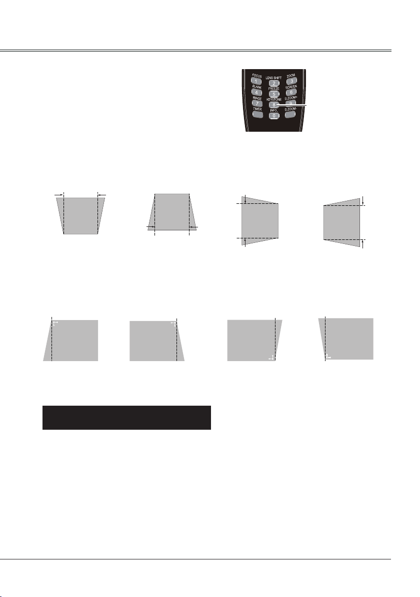
Keystone correction
If a projected image has keystone distortion,
follow the steps below to manually correct the
keystone distortion.
Press KEYSTONE button on the remote
control. The keystone dialog box appears.
Correct keystone distortion with
buttons. Keystone adjustment can be stored.
Horizontal / vertical keystone correction:
Reduce the upper
width with button.
Corners:
Press button
to correct upper left
keystone distortion.
Reduce the lower
width with button.
Press button to
correct upper right
keystone distortion.
Reduce the left
width with button.
Press button to
correct lower right
keystone distortion.
Basic operation
KEYSTONE
Reduce the right
width with button.
Press button
to correct lower left
keystone distortion.
KeystoneKeystone
● The arrows are white when there is no correction.
● The arrows that are used for correction turns red.
● The arrows disappear at the maximum correction.
● If you press the KEYSTONE button on the remote control once more while the keystone dialog
box is being displayed, the keystone adjustment is canceled.
● The adjustable range can be limited depending on the input signal.
29
Page 30
Basic operation
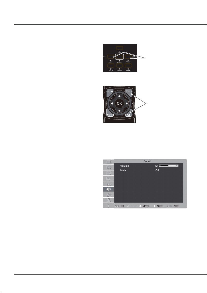
Sound adjust
Direct operation
Volume
Press the VOL +/- button on the side control panel
or on the remote control to adjust the volume.
Menu operation
1 Press MENU button on the remote control to
display the on screen menu.
Press button to the Sound menu icon.
Press OK or SELECT button to enter the
submenu entry.
2 Press
press OK or SELECT button.
3 Press button to select Volume or Mute to
adjust.
button to select Volume and then
Side Control Panel
VOL +/- button
Remote control
VOL +/- button
Sound menu
Volume
Press
to turn up the volume and to turn
down the volume.
Mute
Press OK or SELECT button to switch the mute
function on/off.
30
Page 31

Basic operation
Remote control operation
Using the remote control for some frequently used operations is advisable. Just pressing one of the
buttons enables you to make the desired operation quickly without calling up the on-screen menu.
Remote controlFOCUS
Press FOCUS button on the remote control to
adjust the focus of the image.
FREEZE
Press FREEZE button to freeze the image on
the screen. To cancel the freeze function, press
the FREEZE button again.
IMAGE
Press IMAGE button on the remote control to
select the image mode you desire.
LENS SHIFT
Press LENS SHIFT button on the remote
control to adjust the projector lens location.
FOCUS
FREEZE
IMAGE
LENS SHIFT
D.ZOOM+/-
D.ZOOM +/-
Press D.ZOOM+/- button on the remote control
to enter digital zoom mode.
Note:
See the next page for the description of other buttons.
31
Page 32

Basic operation
BLANK
Press BLANK button to black out the image.
To restore to normal, press the BLANK button
again.
Blank
The screen changes each time you press the
button as follows:
Black out →Normal →Black out →Normal ...
TIMER
Press TIMER button. The timer display “00:00”
appears on the screen and the timer starts to
count time (00:00–59:59).
To stop the Timer, press TIMER button. Press
TIMER button again, and then the Timer display
disappears.
INFO.
Press INFO. button on the remote control
to display current status information of the
projector.
ZOOM
Press ZOOM button on the remote control to
zoom in or zoom out the image.
“Blank” disappears after 4 seconds if there is
no other button operation.
02
Timer display
Remote control
BLANK
TIMER
02
:
INFO.
ZOOM
SCREEN
SCREEN
Press SCREEN button on the remote control to
select the screen size you desire.
32
Page 33

Input select(Analog:VGA IN 1/VGA IN 2/RGBHV)
Direct operation
- Press INPUT button on the side panel to
select VGA IN 1, VGA IN 2 or RGBHV.
- Press VGA or RGBHV button directly on the
remote control.
- Press VGA button directly on the remote
control to switch VGA IN 1 or VGA IN 2.
Side control
INPUT
Remote control
Computer input
VGA
RGBHV
Menu operation
1 Press MENU button on the remote control to
display the screen menu. Press button
to select Input icon, then press OK button.
2 Press button to select VGA IN 1, VGA
IN 2 or RGBHV, then press OK button.
VGA IN 1
When input source is from
computer connected to
Input menu
HDMI
DVI
VGA IN 1
VGA IN 2 Output
Component
S-video
Video
RGBHV
Network
Image Viewer
USB Autorun
Exit Move Next Next
Input
1024x768@60
COMPUTER IN 1 terminal with
VGA cable, please select
VGA IN 1.
VGA IN 2
When input source is from
computer connected to
COMPUTER IN 2/MONITOR
OUT terminal with VGA cable,
please select VGA IN 2.
RGBHV
When input source is from
computer equipment connected
to BNC terminal with BNC*5
cable, please select RGBHV.
Note:
- VGA IN 2 can not be selected when using the VGA IN 2/ VGA OUT terminal as MONITOR
OUT output.(Page 52)
- When the Input Search function is set to On in the Auto setup function, the input signal will be
searched automatically.(Page 49)
33
Page 34

Computer input
Input
Input select(Digital:HDMI/DVI/Network/Image Viewer/USB Autorun )
Direct operation
Side control
- Press INPUT button on control panel or
remote control to select HDMI, DVI, Network,
Image Viewer or USB Autorun .
- Press HDMI or DVI button on the remote
control to select HDMI or DVI.
Menu operation
1 Press MENU button on the remote control to
display the screen menu. Press button
to select Input icon, then press OK button.
2 Press button to select HDMI, DVI,
Network, Image Viewer, USB Autorun ,
then press OK button.
HDMI
When input source is from
equipment connected to HDMI
terminal with HDMI cable, please
select HDMI .
DVI
When input source is from
equipment connected to DVI
terminal with DVI cable, please
select DVI.
Network
When input source is from
network connected to LAN
terminal with LAN cable or WIFI
signal, please select Network.
WIFI does not support hot plug.
USB Autorun
(
When input source is from
)
USB flash device connected to
USB-B terminal, please select
USB Autorun to project the
images stored in USB flash
device.
Connect the USB flash device
between computer and
projector with USB cable.
INPUT
Remote control
HDMI
DVI
USB Autorun
Input menu
HDMI
DVI
VGA IN 1
VGA IN 2 Output
Component
Video
S-video
RGBHV
Network
Image Viewer
USB Autorun
Exit Move Next Next
1024x768@60
Double click "Mirage Presenter ", then you
can project the computer image to the screen.
Connect the audio cable, then you can hear
sound.
34
Click "My Computer" on the
desktop and select Mirage
Presenter (CD driver) .
Page 35

Image Viewer
Computer input
When input source is from USB flash device connected to USB-A terminal, please
select Image Viewer to project the images stored in USB flash device.
When inserting USB flash device into USB-A terminal, the device icon will appear on
the screen.
Press OK button on remote control to enter the device and select the image you
want to project.
Selected Image
Select Exit icon and press OK button to exit Image viewer function.
Exit icon
① ② ③ ④⑤⑥
①NEXT
Move the option to right.
Previous
②
Move the option to left.
③Thumbnail
Enter the thumbnail display mode.
NameOrder
④
Sort by file or folder name
EXIT ON/OFF
⑤
ON/OFF Image rotation.
FileName ON/OFF
⑥
ON/OFF Filename is displayed in
thumbnail mode.
Note:
-When the Input Search function is set to On in the Auto setup function, the input signal will be
searched automatically.(Page 49)
-Image Viewer only supports the flash device with FAT32 and FAT file system and the following
image file formats: JPEG (JPG), Bitmap (BMP), Portable Network Graphic (PNG), Graphics
Interchange Format (GIF) and Tagged Image File Format (TIFF).
35
Page 36

Computer input
Computer system select
The projector automatically tunes to various types of computers with its function of Multi-scan system and
Auto PC Adjustment. If a computer is selected as a signal source, the projector automatically detects the
signal format and tunes to project proper images without any additional setting.
One of the following messages may appear when:
Auto
When the projector cannot recognize
the connected signal conforming to
the provided PC systems, Auto is
displayed on the System Menu box
and the Auto PC Adjustment function
works to display proper images. If
the image is not projected properly, a
manual adjustment is required.
VGA system menu
Input
There is no signal input from computer.
-----
Check the connection between your
computer and projector.
Select computer system manually
The system can also be selected manually.
1 Press MENU button on the side control panel or
remote control to display the on screen menu.
Press
and press OK button.
2 Press button to select System and press
the OK button.
3 Press button to select your required
system, and then press the OK button.
button to select the input source icon,
System 640x480@60
Exit Move Next Next
The PC system menu displays the selected
system.
1024x768@60
√ Note:
When HDMI , DVI or RGBHV is selected, System menu is disable.
36
Page 37

Computer input
Auto PC adjustment
Auto PC Adjustment function is provided to automatically adjust Fine sync, Total dots, Horizontal and
Vertical to conform to your computer.
Menu operation
Auto PC adjustment
1 Press MENU button on side control panel
or remote control to display the on screen menu.
Press
button to select the PC adjust icon
and press OK button.
2 Press button to select Auto PC adj., and
then press OK button.
To store the adjusted parameters
The system parameters adjusted in the Auto PC
Adjustment can be stored in the projector.(Page 38 )
PC adjust menu
Auto PC adj.
Fine sync
Total dots
Horizontal
Vertical
Clamp
Display area H
Display area V
Reset
Mode free
Store
Exit Move Next Next
PC adjust
0
0
1
√ Note:
● Total dots and horizontal & vertical positions of some computers cannot be fully adjusted with this
Auto PC Adjustment function. When the image is not provided properly with this function, manual
adjustments are required.
● The Auto PC Adjustment cannot be operated when 480i, 575i, 480p, 575p, 720p, 1035i or 1080i is
selected in the PC System Menu.
37
Page 38

Computer input
Manual adjustment via PC
Some computers employ special signal formats which may not be tuned by Multi-scan system of this
projector. Manual PC Adjustment is provided for you to precisely adjust several parameters to match
those signal formats. The projector has five independent memory areas to store those parameters
manually adjusted, which allows you to recall the setting for a specic computer.
1 Press MENU button to display the on screen
menu. Press
icon and press OK button.
2 Press button to select the item to be
adjusted and then press OK button to pop up
the corresponding dialog box. Press to set
the value.
Fine sync
To cut off flicker from the image displayed by
pressing
Total dots
Press to adjust the total dots for a cycle so
that it can match the image on computer.
Horizontal
Press
to adjust the horizontal image position.
Vertical
Press
to adjust the vertical image position.
Clamp
Press
the image has dark bars, try this function for
adjustment.
Display area H
Press
to adjust the horizontal area displayed
by the projector.
Display area V
Press
to adjust the vertical area displayed by
the projector.
Reset
To reset the adjusted data, select Reset and press
OK. A conrmation box appears and then select
Yes. All adjustments will return to their previous
gures.
Mode free
To clear the adjusted data, select Mode free and
then press OK. Move OK to highlight the Mode
you want to clear and then press OK.
Store
To store the adjusted data, select Store and then
press OK. Move the red arrow indicator to one of
the Mode 1 to 5 in which you want to store, and
then press OK.
to select the PC Adjustment
to adjust the value.(from 0 to 31).
to adjust the clamp level. When
PC adjustment menu
Auto PC adj.
Fine sync
Total dots
Horizontal
Vertical
Clamp
Display area H
Display area V
Reset
Mode free
Store
Exit Move Next Next
PC adjust
0
0
1
√ Note:
If you select 480i, 575i, 480p, 575p, 720p, 1035i
or 1080i from the system menu, the functions of
both horizontal image and vertical image will be
disabled.
38
Page 39

Image Select
Direct operation
Press IMAGE button on the remote control to
select your required image quality.
Computer input
Remote control
Menu operation
1. Press MENU button to display the
screen menu. Press to select the
Image select icon and press OK button.
2. Press to select your required image
mode and then press OK.
Dynamic
For viewing images in a bright room.
Normal
Normal image quality preset by the system on
the projector.
Cinema
For watching movies with multiple gray scale
levels.
Blackboard (Green)
For viewing the image projected on a
blackboard (green). by enhancing the image
quality. This is mainly effective on a green
colored board instead of a black colored board.
Colorboard
For images projected onto the red, blue, yellow,
or green wallpaper.
IMAGE
Image select menu
Dynamic
Normal
Cinema
Blackboard (Green)
Colorboard Red
User Image
Exit Move Next Next
Image select
User Image
Image quality preset by the user in the Image
adjustment menu.
39
Page 40

Computer input
Image adjust
Contrast 32
Brightness
32
Color temp. Mid
Red 32
Green
32
Blue
32
Sharpness
8
Gamma
8
Exit
Move
Next Next
Image adjust
1 Press MENU button to display the screen
menu, press to select image adjust icon
and press OK button.
2 Press to select the setting item, then
press OK button, adjust dialogue box
appears, press to set the value.
Contrast
Press to decrease the contrast and to
increase it.
Brightness
Press to decrease the brightness and to
increase it.
Color temp
Press to select your desired color
temperature.( Low, Mid and High )
Red(White balance)
Press to lighten the red tone and to
deepen it.
Green(White balance)
Press to lighten the green tone and to
deepen it.
Blue(White balance)
Press to lighten the blue tone and to
deepen it.
Sharpness
Press to decrease the sharpness of an
image and to increase it.
Gamma
Press to adjust the gray scale level for
better balance of contrast.
Image adjust menu
40
Page 41

Screen size adjust
宽屏
真实
Normal
Wide
True
Full
Custom
Digital zoom +
Digital zoom -
Screen
Exit Move Next Next
The screen size can be reset to the value as you desire.
Direct operation
Press SCREEN button on the remote control to
select your required screen quality.
Menu operation
1 Press MENU button to display the screen
menu. Press button to select screen icon
and then press OK button.
2 Press to select your required item and
then press OK button.
Normal
To project images in the same aspect ratio with
the input signals.
Wide
To provide an image with an aspect ratio of
16:9 by expanding the image width uniformly.
True
Provide images in original size. When the
original image size is larger than the screen
size, the projector enters display area selection
mode automatically. Press
a display area. The arrow turns red upon
adjustment and disappears upon the maximum
limit.
Full
To provide an image to t the screen.
Custom
Adjust the proportion and position of the screen
manually.
When selecting this item, press and the
corresponding interface appears on the screen.
Press button to adjust your required item.
Scale H / Scale V: Adjust the horizontal/vertical
screen scale.
H&V: When set to “On”, the aspect ratio is
xed. The Scale V appears dimmed and
becomes unavailable. Adjust Scale H, and
then the screen scale is automatically modied
based on the aspect ratio.
Position H / Position V: Adjust the horizontal/
vertical screen position.
Common: Save the adjusted scale to all the
inputs. Press OK at Common to display a
conrmation box. To save the scale, press OK.
When Custom is selected, the saved scale is
used.
Reset: Reset all the adjusted values. Press OK
at Reset to display a conrmation box. To set,
press OK at “Yes”.
to select
Remote control
OK
Screen menu
Computer input
SCREEN
41
Page 42

Computer input
Digital zoom +
After you select the digital zoom +, the onscreen menu will disappear, while the
information on digital zoom + appears.
You can press SELECT button on the side
control panel or OK button on the remote
control to zoom in the image size, and press
▲▼◄►to move the image horizontally and
vertically.
The moving is effective only when the image is
larger than the size of the screen.
Digital zoom -
After you select the digital zoom -, the onscreen menu will disappear, while the
information on digital zoom - appears. You can
press SELECT button on the side control panel
or OK button on the remote control to zoom out
the image size.
To return to original screen size, select the
screen size from menu “Screen Size Adjust”,
or re-select input source from menu “Input
Select”, or press OK button to adjust the
screen size.
Note:
• The projector does not support images with
resolution higher than 1920x1200. If the
resolution of your PC screen is so, please
re- set to lower resolution before connecting
to the projector.
• Image data other than XGA (1024 x 768) will
be modified to those applicable to the screen
size in the initial mode.
• If no signal is detected in the PC system
menu, options of True, Full and Digital
zoom + are not available.
42
Page 43

Input select (Component, S-video, Video )
Direct operation
Side control panel
Video input
Press INPUT button on the side control panel
or press Component, Video or S-video button
on the remote to select Component,Video or
S-video.
Menu operation
1 Press MENU button on the remote control to
display the screen menu. Press button
to select Input icon, then press OK button.
2 Press button to select Component,
Video or S-video, then press OK button.
Component
Select Component when the
input source is from the video
equipment connected to Y, Cb/
Pb and Cr/Pr terminals with a
component cable.
INPUT
Remote control
COMPONENT
Input menu
HDMI
DVI
VGA IN 1
VGA IN 2 Output
Component
Video
S-video
RGBHV
Network
Image Viewer
USB Autorun
Exit Move Next Next
VIDEO
S-VIDEO
Input
1024x768@60
Video
S-video
Select Video when the video input
signal is connected to VIDEO
terminal.
Select S-video when the video
input signal is connected to
S-VIDEO terminal.
43
Page 44

Video input
Input
System Component
Auto
1080i
1035i
720p
575p
480p
575i
480i
Exit Move - - - - SelectBack
视频一
Input
System Video
Auto
PAL
SECAM
NTSC
NTSC4.43
PAL-M
PAL-N
Exit Back Move Select
Video system select
1 Press MENU button on the remote control to
display the screen menu. Press button
to select Input icon, then press OK button.
2 Press button to select Component,
Video or S-video, and then press OK
button.
3 Press button to select System, and press
the OK button.Press
required system, and then press the OK button.
Video or S-video
Auto
The projector automatically detects an
incoming video system,and adjusts itself to
optimize its performance. When Video System
is PAL-M or PAL-N, select the system manually.
PAL/SECAM/NTSC/NTSC4.43/PAL-M/PAL-N
If the projector cannot reproduce proper video
images, select a specific broadcast signal
format from PAL, SECAM, NTSC,NTSC 4.43,
PAL-M and PAL-N.
button to select your
Video system menu(Video or S-video)
Component
Auto
The projector automatically detects an input
video system,and adjusts itself to optimize its
performance.
Component video signal format
If the projector cannot reproduce proper video
images, select a specific broadcast signal
format from 480i, 575i, 480p, 575p, 720p,
1035i and 1080i.
44
Video system menu(Component)
Page 45

Image Select
Direct operation
Press IMAGE button on the remote control to
select your required image quality.
Video input
Remote control
Menu operation
1. Press MENU button to display the
screen menu. Press to select the
Image Select icon and press OK button.
2. Press to select image mode you
desire and then press OK.
Dynamic
For viewing images in a bright room.
Normal
Normal image quality preset by the system on
the projector.
Cinema
For watching movies with multiple gray scale
levels.
Blackboard (Green)
For viewing the image projected on a
blackboard (green) by enhancing the image
quality. This is mainly effective on a green
colored board instead of a black colored board.
Colorboard
For images projected onto the red, blue, yellow,
or green wallpaper.
IMAGE
Image select menu
Dynamic
Normal
Cinema
Blackboard (Green)
Colorboard Red
User Image
Exit Move Next Next
Image select
User Image
Image quality preset by the user in the Image
adjustment menu.(Page 46)
45
Page 46

Video input
Image adjust
Contrast 32
Brightness
32
Color 32
Tint 32
Red 16
Green
36
Blue
36
Sharpness
8
Gamma
8
Noise rdduction On
Progressive L1
Exit
Move
Next Next
Image adjust
1 Press MENU button to display the screen
menu, press to select image adjust icon
and press OK button.
2 Press to select the item and press OK
button, adjust dialogue box appears. Press
to set the value.
Contrast
Press to decrease the contrast and to
increase it.
Brightness
Press to decrease the brightness and to
increase it.
Color
Press to decrease the Chroma and to
increase it.
Tint
Press to select the appropriate tone for the
image.
Red(White balance)
Press to lighten the red tone and to
deepen it.
Green(White balance)
Press to lighten the green tone and to
deepen it.
Blue(White balance)
Press to lighten the blue tone and to
deepen it.
Sharpness
Press to decrease the sharpness of an
image and to increase it.
Gamma
Press to adjust the gray scale level for
better balance of contrast.
Noise reduction
To reduce noise interference on the screen.
Select the function to get smoother images.
Progressive
An interlaced video signal can be displayed
in a progressive image. Select one of the
following options:
Off.....Disabled.
L1......For a motion image.
L2......For a still image.
Film...For watching a lm. With this function,
the projector reproduces images faithful
to the original lm quality,reducing
distortion.
46
Image adjust menu
Page 47

Screen size adjust
宽屏
真实
Normal
Full
Wide
Custom
Screen
Exit Move Next Next
The screen size can be reset as you desire.
1 Press MENU button to display the screen
menu. Press button to select screen
icon and then press OK button.
2 Press to select the item you desire and
then press OK button.
Normal
To project images in the same aspect ratio with
the input signals.
Full
To provide an image to t the screen.
Wide
To provide an image with an aspect ratio of
16:9 by expanding the image width uniformly.
Custom
Adjust the proportion and position of the screen
manually.
Press button at Custom and the Custom
appears on the screen. Press button to
adjust your required item.
Scale H/Scale V: Adjust H/V screen scale.
H&V: When set to “On”, the aspect ratio is
xed. The Scale V appears dimmed and
becomes unavailable. Adjust Scale H, and
then the screen scale is automatically modied
based on the aspect ratio.
Position H/Position V: Adjust the H/V image
position.
Common: Save the adjusted scale to all the
inputs. Press OK button at Common to display
a conrmation box. To save the scale, press
OK button at “YES”. When Custom is selected,
the saved scale is used.
Reset: Reset all the adjusted values. Press OK
button at Reset to display a conrmation box.
To set, press OK button at “YES”.
Remote control
OK
Screen menu
Video input
SCREEN
Note:
● If no signal is detected, the system will be
automatically set as normal state and the
adjustment prompt box disappears.
● The Scale H/Scale V and Position H/Position V
shall be adjusted according to the input signal.
47
Page 48

Setting
Setting
The projector has Setup menu that allows you to set the other various function described as
follows.
1 Press MENU button to display the screen
menu. Press button to select Setting
icon and then press OK button.
2 Press to select the desired item to be
adjusted, and then press to switch the
items.
3. Press button to select desired item and
press OK button.
Language
The language used in screen menu is available
in Traditional Chinese, Simple Chinese,
English, French, Spanish, Portuguese,
German, Italian, Japanese, Korean, Russian,
Finnish, Dutch, Thai, Vietnam, Turkish, African,
Indonesian, Farsi and Arabian.
Setting menu
Language English
OSD setting
菜单设置
Auto setup
Keystone
Blue Back On
Display On
Logo
Ceiling Auto
Rear Off
Terminal VGA OUT
Standby mode
Exit Move Next
Power management Off
On start Off
Closed caption
Lamp control
Test Pattern Off
Security
Cooling fast Off
High land Off
Filter counter
Warning log
Factory default
Exit MoveBack Next Next
IRIS On
Lamp Counter
Remote Control
Setting
Setting
Setting
1/3
Eco
Next
2/3
A
3/3
48
Exit MoveBack ---- Next
Page 49

Setting
Exit Move ----
Next
Back
1/3
Auto setup
Input search On
Auto PC adj. On
Setting
Exit Move ----
Next
Back
1/3
OSD setting
Menu position
Translucent Off
Background Color 0
OSD setting
This item is used to set the position, translucent
or background color of the sreen menu.
Menu position
This function enables you to change the
position for displaying the screen menu. Select
Menu position, and press Select button. Every
time you press OK button, the screen position
will change as follows:
upper left →upper right →Center → lower left
→lower right →upper left →…
Translucent
This function enables you to change the
transparency for displaying screen menu.
Press button to select Off, High, Mid or
Low.
Background color
This function enables you to change the
background color for displaying screen menu.
Press to select from 0-6.
Auto setup
Allows you to perform input search, auto PC
adj. , press the AUTO SETUP button on the
side control or AUTO button on the remote
control. The functions can be switched based
on the steps below.
Setting
OSD setting menu
Auto setup menu
Input search
Allows you to automatically detect input
signals. It stops when a signal is found.
Press to select an option below:
Off........Disabled.
On........Enabled. This function is used to
detect input signals automatically ,
and stops when nding a signal.
Auto PC adj
On........Press the AUTO SETUP button on
the side control panel or AUTO
button on the remote control to
enable Auto PC adj. function
automatically.
Off........Disable Auto PC adj. function.
Note:
• Only the last selected input source can be
detected.
• If the INPUT button on the side control or on
the remote control is pressed during Input
search is in progress, Input search will stop
and go back to the previous input signal.
• Fine sync., Total dots, Horizontal and Vertical
position of some computers cannot be
fully adjusted with the Auto PC Adjustment
function. When the image is not provided
properly with this operation, manual
adjustments are required.
49
Page 50

Setting
Setting
Exit Move ----
Next
Back
1/3
Keystone
Keystone Store
H/V Keystone
Corner
Keystone
This function is used to reset the keystone
correction after the AC power cord is
unplugged. Press
below:
Keystone
Store..............Store the keystone correction
even when the AC power cord
is unplugged.
Reset .............Reset the keystone correction
when the AC power cord is
unplugged.
H/V Keystone
Press
to correct keystone distortion in
horizontal and vertical position.
Corner
Press button on the remote control to
select Corner and press OK button. Corner
correction dialogue window appears on the
screen.
Press
buttons to correct corner
keystone distortion.Correcting order is as
followings:
upper left→ upper right → lower right → lower
left→...
Press button to correct upper left keystone
distortion.
Press button to correct upper right
keystone distortion.
Press button to correct lower right
keystone distortion.
Press button to correct lower left keystone
distortion.
Blue back
Enable to select the screen background of the
projector when there is no signal detected.
Press button on the remote control to
switch on/off.
On ........Enable the blue background for
projection.
Off ........Disable the blue background.
Display
Enable to decide whether to display the onstart displays.(Including countdown)
Press button on the remote control to
switch on/off.
On ............... Display startup screen.
Off ............... Display the input image instead
of the on-start screen.
to select the items
Keystone menu
Corners:
Press button
to correct upper left
keystone distortion.
Press button to
correct lower right
keystone distortion.
Press button to
correct upper right
keystone distortion.
Press button
to correct lower left
keystone distortion.
50
Page 51

Setting
Setting
Exit Move ----
Next
Back
1/3
Logo
Logo select Default
Logo PIN code lock
Logo PIN code change
Logo (Logo and Logo PIN code settings)
This function allows you to customize the screen logo with Logo select, Logo PIN code lock
and Logo PIN code change functions.
LOGO menu
Logo select
This function decides on the starting-up
display from among following options.
Press button on the remote control to
select from Default and Off:
Default .... Show the factory-set logo.
Off ........... Show the countdown display only.
Logo PIN code lock
This function prevents an unauthorized person from changing the screen logo.
Off ...... .....The screen logo can be selected default or off freely from the Logo select Menu.
On ...... .....The screen logo cannot be changed without a Logo PIN code.
If you want to change the Logo PIN code lock setting, press the OK button and the Logo PIN
code dialog box appears. Enter a Logo PIN code by following the steps below.
Password resetting
Press buttons to enter a number. Press the button to x the number and move the red
frame pointer to the next box. The number changes to “*”. If you fixed an incorrect number,
use the Point button to move the pointer to the number you want to correct, and then press
enter the correct number.
Repeat this step to complete entering a three-digit number.
After entering the three-digit number, move the pointer to Set. Press the SELECT button so that
you can start to operate the projector.
Logo PIN code change
Logo PIN code can be changed to your desired three- digit number. Press the SELECT button
to select Logo PIN code change. Logo Pin code dialog box appears, use the Point buttons
to enter the correct code. The New Logo PIN code input dialog box appears. Set a new Logo
PIN code, conrmation box appears, choose yes to set the new Logo Pin code.
Be sure to note the new Logo PIN code and keep it on hand. If you lost the number, you could
no longer change the Logo PIN code setting.
If you entered an incorrect Logo PIN code, Logo PIN code and the number (***) will turn red for
a moment. Enter the correct Logo PIN code all over again.
Caution:
When you have changed the logo pin code, write down the new pin code in column of the
logo pin code no. Memo on page 74, and keep it securely. Should the logo pin code be lost or
forgotten, the logo pin code setting can no longer be changed.
51
Page 52

Setting
Exit Move ----
Next
Back
1/3
Terminal
VGA IN 2
VGA OUT
Setting
Ceiling
This function is used to project the image from
a ceiling-mounted projector.
Press button on the remote control to
select the item you desire.
On.......The image will be top/bottom and left/
right reversed.
Auto.... The projector automatically identies its
vertical or inverse state.
Off ......Disable this function.
Rear
When the function is set to On, the image
is left/right reversed. Enable to project the
image to a rear projection screen.
Press button on the remote control to
select the item you desire.
On.......The image will be left/right reversed.
Off ......Disable this function.
Terminal
The VGA IN 2/VGA OUT terminal can be
used as computer input or monitor output.
Press to select VGA IN 2 or VGA OUT.
VGA IN 2 ....VGA IN 2 input.
VGA OUT......VGA output.
Terminal menu
Standby mode
This function is available when operating the
projector via network.
Press button on the remote control to
select the item you desire.
Eco .......In this state, network function, VGA
OUT is disable after turning off the
projector. No command but POWER
ON is enable for RS232 after turning
off the projector.
Normal ..Supply the power to the network
function even after turning off the
projector. You can turn on/ off the
projector via network or modify
network environment while the
projector is turned off.
52
Page 53

Power management
No signal
01 : 20
Setting
Exit Move ----
Next
Back
2/3
Power management
Ready
Shut down
Off
Timer 5 Min
Ready countdown 0 Min
For reducing power consumption as well
as maintaining the lamp life, the Power
management function turns off the projection
lamp when the projector is not operated for a
certain period.
Select one of the following options:
Ready ................... When the lamp has been
fully cooled down, the
POWER indicator changes
to green blinking.In this
condition, the projection
lamp will be turned on if
the input signal is
reconnected or any button
on the side control or
remote control is pressed.
The projector will be power
off while press the Power
button on the side control
or remote control.
Shut down .............When the lamp has been
fully cooled down, the
power will be turned off.
Off .........................Power management
function is off.
Timer .....................If the input signal is
interrupted and no button is
pressed for more than 30
seconds, the timer display
with No signal appears.
It starts the countdown until
the lamp is turned off. Press
buttons to set the
Timer (1-30min.)
Ready countdown..Set the time that ready
status transfers to standby
status automatically.
(0-30min.0 Min: not transfer
automatically) In ready
status, press POWER
button to switch to standby
status, and press any other
button to turn on the
projector.
Setting
Power management menu
Power management
Time left before Lamp is off.
√ Note:
Factory default is Ready: 5 Min.
Ready countdown: 0 Min.
On start
Enable the projector to be turned on
automatically just by connecting the AC power
cord to an outlet when this function is set to On.
53
Page 54

Setting
Setting
Exit Move ----
Next
Back
2/3
Close caption
Closed caption Off
Color Color
Closed Caption
Allows the subtitle to be displayed for the audio contents or other information. If the input source
contains closed caption, you can enable this function and change the channel.
Closed caption
Press to select OFF, CC1, CC2, CC3 or
CC4.
Color
Press to select Color or White.
√ Note:
Only under the following circumstances you can select Closed Caption:
● The input is composite video signal or S-Video in the NTSC system.
● The system should be set to NTSC or Auto in the video system.
● The icon of Closed Caption appears dimmed when unavailable.
● Closed Caption cannot be selected when the screen menu and Timer is displayed.
Lamp control
Change the brightness of the screen.
Normal .....Normal brightness.
Auto..........Adjust the lamp brightness
according to the input signal.
Eco ..........Lower brightness, reducing
power consumption and
extending the lamp life.
Closed caption menu
Test Pattern
This function is used to set the internal test
signal.
Press to select Off or 1-12.
54
Page 55

Setting
Setting
Exit Move ----
Next
Back
2/3
Security
Key lock
PIN code lock Off
PIN code change
Security (Key lock and PIN code lock)
This function allows you to use the Key lock and
PIN code lock function to set the security for the
projector operation.
Key lock
This function locks the side control and
remote control buttons to prevent operation by
unauthorized persons. Select Key lock and then
press the SELECT button, and select the desired
item by pressing button.
Off ......................... Unlocked.
Projector ............... Lock the operation of the
side control. To unlock,
use the remote control.
Remote Control ..... Lock the operation of the
remote control. To unlock,
use the side control.
If the side control accidentally becomes locked
and you do not have the remote control nearby
or there is something wrong with your remote
control, contact the dealer where you purchased
the projector or the service center.
PIN code lock
This function prevents the projector from being operated by unauthorized persons and provides the
following setting options for security.
Off ............ Unlocked.
On ........... Enter the PIN code every time turning on the projector.
Whenever you change the PIN code lock setting or the PIN code (the three-digit number), you are
required to enter the PIN code. The “111” is set as the initial PIN code at the factory.
If you want to change the PIN code lock setting, press SELECT button and the PIN code dialog box
appears.
Enter a PIN code
Press buttons to enter a number. Press button to x the number and move the red frame
pointer to the next box. The number changes to “*”. If you fixed an incorrect number, press
button to move the pointer to the number you want to correct, and then press enter the
correct number.
Repeat this step to complete entering a three-digit number.
After entering the three-digit number, move the pointer to “Set”. Press the SELECT button so that
you can start to operate the projector.
If you entered an incorrect PIN code, PIN code and the number (***) will turn red for a moment.
Enter the correct PIN code all over again.
Change the PIN code lock setting
Press buttons to select Yes or No,and then press the SELECT button to make a choice.
PIN code change
The PIN code can be changed to your desired three-digit number. Press SELECT button to select
PIN code change. Pin code dialog box appears, Press buttons to enter the correct code. The
New PIN code input dialog box appears. Set a new PIN code.
Caution:
When you have changed the pin code, write down the new pin code in column of the pin code no. Memo
on page 74, and keep it securely. If you forget your pin code, the projector can no longer be started.
Security menu
55
Page 56

Setting
Cooling fast
This function provides the following options in the cooling fans’ operation after turning off the
projector.
Off......... Normal operation.
On ........ Faster and louder than Normal, cooling time is shorter.
High land
Enable to control the fan through the Setup menu.
You can select the running speed of the fan according to the altitude of the location where the
projector is installed.
Off......Normal speed. Set it so if the projector is operated at a lower altitude.
On......Faster than Off. Set it so if the projector is operated at a higher altitude because fans will
produce weaker effects.
Filter counter
This function is used to set a frequency for
the lter cleaning.
When the projector reached a specied time
between cleanings, a Filter warning icon
appears on the screen, notifying the cleaning
is necessary. After cleaning the lter, be sure
to select lter counter reset and set the timer.
The Filter warning icon will not turn off until
the Filter counter is reset.
Filter counter.............The time that lter used.
Timer.........................Frequency for lter
cleaning.
Filter counter reset....Reset the lter counter.
Warning log
Recording abnormal operations, facilitating to diagnosing errors. The log lists the latest 9 warning
messages in time sequence.(The latest warning message is arranged at the top of the warning log
list.)
Filter counter menu
Filter counter
Filter counter 85 H
Timer 200 H
Filter counter reset
Back
Exit Move ----
Setting
2/3
Next
Note:
When Factory Default is selected, all log records will be deleted.
Factory default
This function returns all setting values except for the User logo, PIN code lock, Logo PIN code
lock, Lamp counter and Filter counter to the factory default settings.
IRIS
This function is used to increase the contrast of the image.
On.... Enable Iris function, increase the contrast of the image.
Off....Disable Iris function.
Lamp Counter
This function is used to display the cumulative lamp operating time and reset the lamp counter.
When the total lighting time of a lamp exceeds the recommended total hours of use, the Lamp
replacement icon (page 61) will appear on the screen, indicating that the end of lamp life is
reached.
When replacing the projection lamp, reset lamp counter. See "Resetting the Lamp Counter" on
page 62.
56
Page 57

Information
Lamp counter 36 H
Power managementter Off
Remote control code
The projector is assigned 10 different remote control codes (Code 0-9).
The remote control code should be the same one from the projector and the remote control.
As setting the remote control as Code 7 to operate the projector, the remote control code on the
projector also must be switched to Code 7.
Change the projector's code: Select "Remote control" in setting menu. Choose the code.
Change the remote control code: Press the OK and the number key (0-9) on the remote control for
more than 5 seconds to switch the code.
Note:
- The default remote control code is Code 0.
- If the remote control code set on the projector and remote control is different, it will not execute
any operation. In this case, switch the remote control code to the same one with the projector.
- The remote control code will be reset after the battery is removed for a long period of time.
The information menu is used to detect signal of projected image and running state.
Menu operation
Press MENU button to display the screen
menu. Press to select information icon,
the information menu will appear and the
information is displayed.Shown as the right
image.
See below for displayed information.
Input
The selected input source is displayed.
H-sync freq .
The horizontal frequency of the input signal is
displayed in KHz or - - - -KHz when no signal.
V-sync freq .
The vertical frequency of the input signal is
displayed in Hz or - - - - Hz when no signal.
Numbers of Hz doubles when during Interlace.
Screen
The selected screen size is displayed.
Language
The selected language is displayed.
Input S-video
H-sync freq. ---- KHz
V-sync freq. ---- Hz
Screen Normal
Language English
Lamp status
Key lock
Exit Move
Information
0 H
5 Min
Lamp status
The selected lamp mode is displayed.
Lamp Time
Display the cumulative used time of the lamp.
Power management
Off, Ready or Shut down is displayed.
Key lock
Display Off, Remote Control or the Projector.
57
Page 58

Maintenance and cleaning
WARNING TEMP indicator
The WARNING TEMP indicator shows the state of the function which protects the projector. Check
the state of the WARNING TEMP indicator and the POWER indicator to take proper maintenance.
The projector is shut down and the WARNING
TEMP indicator is blinking red.
When the temperature inside the projector
exceeds the normal temperature, the projector
is automatically shut down to protect internal
components. The POWER indicator is blinking
while the projector is being cooled down. When
the projector has cooled down enough (to its
normal operating temperature), it can be turned
on again by pressing the POWER button.
Note:
The WARNING TEMP indicator continues
to blink even after the temperature inside
the projector returns to normal. When the
projector is turned on again, the
WARNING TEMP indicator stops blinking.
Check the items below:
– Did you provide appropriate space for the
projector to be ventilated?
Check the installing condition to see if
ventilation slots are not blocked.
– Has the projector been installed near the
duct or vent of an air conditioning?
Move the installation of the projector away
from the duct or vent.
– Are the air lters clean? Clean the air lters
periodically.
The projector is shut down and the WARNING
TEMP indicator lights red.
When the projector detects an abnormal
condition, it is automatically shut down to
protect the internal components and the
WARNING TEMP indicator lights red. In this
case, unplug the AC power cord and plug it,
and then turn on the projector once again to
verify operation. If the projector cannot be
turned on and the WARNING TEMP indicator
lights red, unplug the AC power cord and
contact the service station for servicing and
maintenance.
Caution
Do not leave the projector with the AC power cord connected under an abnormal condition.
It may result in re or electric shock.
Indicator
WARNING TEMP indicator blinks red.
Indicator
WARNING TEMP indicator lights red.
58
Page 59

Maintenance and cleaning
Cleaning the air lter
The air lter prevents dust from accumulating on the surface of the optical elements inside
the projector. Should the air lter become clogged with dust particles, it will reduce cooling
fans’ effectiveness and may result in a buildup of internal heat and adversely affects the life of
the projector. If the Filter warning icon appears on the screen, the air lter should be cleaned
immediately. Clean the air lter following the steps below.
1 Turn off the projector, and unplug the AC
power cord from the AC outlet.
2 Remove the air lter.
3 Gently clean the lter with a brush.
4 Reinstall the lter into the projector properly.
Caution
Do not operate the projector with
the air lter removed. Dust may
accumulate on the optical elements,
degrading image quality.
Do not put any small objects into the
air intake vents. Otherwise, it may
result in malfunction of the projector.
Resetting the lter counter
Be sure to reset the lter counter after cleaning
or replacing the lter.
1. Press Menu on the remote control to display
the on screen menu. Press to select
the icon for the setting menu. Then press
or press OK.
2. Press to select Filter counter, and then
press or press Select. Press to select
Filter counter reset, then press OK. At the
time, you will see the prompt information
“Filter counter Reset?” displayed on the
screen. Select Yes.
3. When another dialog box pops up, you
should select Yes and reset the lter.
Recommendation
We recommend avoiding dusty/smoky
environments when you operate the projector.
Usage in these environments may cause poor
image quality.
When you use the projector under dusty or
smoky conditions, dust may accumulate on the
lens, LCD panels, or optical elements inside the
projector. When the symptoms above are
noticed, contact your authorized dealer or
service station for proper cleaning.
Air lter
Replacement Filter Type
ORDER REPLACEMENT FILTER
Replacement lter can be ordered through your dealer. When ordering a lter, give the following
information to the dealer.
Model No. of your projector: LC-XN200, LC-WXN200,LC-XN200L, LC-WXN200L.
59
Page 60

Maintenance and cleaning
Lens cover
When moving the projector or the projector is
not under use for a long time, please put on the
lens cover.
Clean the projector lens
Unplug the AC power cord before cleaning.
Gently wipe the projection lens with a cleaning
cloth that contains non-abrasive camera
lens cleaner, or use a lens cleaning paper or
commercially available air blower to clean the
lens.
Avoid using an excessive amount of cleaner.
Abrasive cleaners, solvents, or other harsh
chemicals might scratch the surface of lens.
Clean the cabinet
Unplug the AC power cord before cleaning.
Gently wipe the projector surface with a soft
dry cleaning cloth. When the cabinet is heavily
soiled, use a small amount of mild detergent
and nish with a soft dry cleaning cloth. Avoid
using an excessive amount of cleaner. Abrasive
cleaners, solvents, or other harsh chemicals
might scratch the surface of the cabinet.
When the projector is not in use, put the
projector in a pouch to protect it from dust and
scratches.
60
Page 61

Maintenance and cleaning
Replace the lamp
When the projection lamp of the projector
reaches its end of life,the Lamp replacement
icon appears on the screen and LAMP
indicator lights yellow. Replace the lamp with
a new one of the same type promptly. The
timing when the LAMP indicator should light is
depending on the lamp mode.
CAUTION
As temperature inside the projector is high,
you should cool the projector for at least 45
minutes before you open the lamp cover.
CAUTION
When the lamp isn’t illuminated, it may indicate that the lamp has been damaged.
When you replace the lamp in a projector installed on the ceiling, you should stand beside
the lamp cover other than under it; for the broken glass may fall down to hurt you. To do that,
remove the lamp cover gently to avoid being hurt by the dropped glass. If glass drops into
your eyes or mouth, you should see the doctor immediately.
To replace the lamp, follow the steps below:
Indicator
Lamp Replace
݁സ
CAUTION
For the sake of safety, only use the lamp of
the same model. Never drop the lamp onto the
ground nor touch the glass bulb! The glass can
shatter and hurt.
Lamp icon
When the projection
lamp of the projector
reaches its end of
life, LAMP indicator
lights yellow.
1. Power off the projector and unplug the
power cord. Then let the projector cool for at
least 45 minutes.
2. Loosen the screws on the lamp cover and
open the cover.
3. Make sure the lamp is well protected and
remove three screws. Hold the handle and
take out the lamp.
4. Install a new lamp with the same model and
tighten the three screws. Make sure the
installation is correct. Put lamp cover in
place and then tighten the screws.
5. Plug the AC power cord and power on the
projector.
Screw
Handle
Screw
Screw
Lamp
Screw
Lamp
cover
61
Page 62

Maintenance and cleaning
Resetting the Lamp Counter
Be sure to reset the Lamp counter after the lamp is replaced. When the Lamp counter
is reset, the LAMP REPLACE indicator stops lighting and the Lamp replacement icon
disappears.
1 Press the MENU button to display the
On-Screen Menu. Press buttons to
select Setting icon and then press or
the SELECT button.
2 Press buttons to select LAMP
counter reset and then press SELECT
button. Lamp replacement counter
Reset? appears. Select Yes to continue.
3 Another confirmation dialog box
appears, select Yes to reset the Lamp
counter.
√ Note:
Do not reset the Lamp counter without
implementing lamp replacement. Be sure
to reset the Lamp counter only after
replacing the lamp.
Lamp counter
Lamp counter 67 H
Lamp counter reset
Exit ----Back ---- Next
Setting
OK?
No
3/3
62
Page 63

Maintenance and cleaning
Replacement Lamp Type
ORDER REPLACEMENT LAMP
Replacement lamp can be ordered through your dealer. When ordering a projection lamp, give the
following information to the dealer.
Model No. of your projector: LC-XN200, LC-WXN200,LC-XN200L, LC-WXN200L
LAMP HANDLING PRECAUTIONS
This projector uses a high-pressure lamp which must be handled carefully and properly.
Improper handling may result in accidents, injury, or create a re hazard.
● Lamp life may differ from lamp to lamp and according to the environment of use. There is
no guarantee of the same life for each lamp. Some lamps may fail or terminate their life
in a shorter period of time than other similar lamps.
● If the projector indicates that the lamp should be replaced, i.e., if the LAMP REPLACE
indicator lights up, replace the lamp with a new one IMMEDIATELY after the projector
has cooled down. (Follow carefully the instructions in the Lamp Replacement section of
this manual.) Continuous use of the lamp with the LAMP REPLACE indicator lighted may
increase the risk of lamp explosion.
● A Lamp may explode as a result of vibration, shock or degradation as a result of hours of
use as its lifetime draws to an end. Risk of explosion may differ according to the
environment or conditions in which the projector and lamp are being used.
IF A LAMP EXPLODES, THE FOLLOWING SAFETY PRECAUTIONS SHOULD
BE TAKEN .
If a lamp explodes, disconnect the projector’s AC plug from the AC outlet immediately.
Contact an authorized service station for a checkup of the unit and replacement of the
lamp. Additionally, check carefully to ensure that there are no broken shards or pieces of
glass around the projector or coming out from the cooling air circulation holes. Any broken
shards found should be cleaned up carefully. No one should check the inside of the projector
except those who are authorized trained technicians and who are familiar with projector
service. Inappropriate attempts to service the unit by anyone, especially those who are not
appropriately trained to do so, may result in an accident or injury caused by pieces of broken
glass.
63
Page 64

Appendix
Troubleshooting
Before calling your dealer or service center for assistance, check the items below once again.
- Make sure you have properly connected the projector to peripheral equipment.
- Make sure all equipment is connected to the AC outlet and the power is turned on.
- If the projector does not project an image when it is connected to a PC, restart the PC.
Problems – Solutions
No power - Plug the power cord of the projector into the AC power outlet.
No initial displaying - Make sure both Display and count-down functions are enabled.(P50,P53)
Initial displaying is inconsistent
with factory defaults
Input signals are automatically
switched (can’t be switched)
When input is pressed during
startup, a lter icon appears.
An icon of non-input mode or lamp
mode appears
Ambiguous images - Adjust the focus.
Image turns over leftward/
rightward
Image turns over upward/
downward
Image not bright enough - Check whether the contrast or brightness is adjusted correctly.(P40,46)
No image - Check the connection between PC or video equipment with the projector.
- Check whether the power indicator turns red.
- Only when the power indicator turns red then you can power on the
projector again.
- Check the Warning Temp indicator. If it is blinking red, you can’t
power on.(P58)
- Check the projection lamp.(P61)
- Unlock the “key lock” function.(P55)
- Make sure the item Default or Off is not selected in Logo select.(P51)
- Adjust the search function of input source properly.
-This icon warns that the lter needs to be replaced.
-This icon indicates the replacement of lamp or warns for the
lter.
- Set a more proper projection distance.
- Check whether the lens needs to be cleaned.
- When moved from a environment with low temperature to
the one with higher temperature, water will be condensed
on the lens. If so, you have to wait till the condensed water
disappears.
- Check the function of “ceiling/rear”.(P52)
- Check the function of “ceiling”.
- Check whether the image mode is properly selected.(P39,45)
- Check the function of lamp brightness adjusting.(P54)
- Check the lamp replace indicator. If the indicator is illuminated, it means
the service life of the lamp is over. You should replace the lamp with a
new one of the same model immediately.
- Check whether the signal from PC is correct. If connected to
certain laptops, the settings of their monitors need to be
changed.You can refer to the operating instructions of the PC
for such modication.
- Images can show up only about 20 seconds after the projector
is powered on.
- Check the input signal, color system, video system or PC
system mode.
- Make sure that the temperature doesn’t exceed the permitted
operating temperature (41˚F–95˚F [5˚C–35˚C]).
- If blank function is enabled, no image will appear on
the screen. You can then press BLANK key or other keys.(P33)
64
Page 65

Appendix
Problems – Solutions
Abnormal color - Check the input signal, color system, video system or PC system
Some information can’t be seen
in the operation.
Automatic adjustment through
PC can’t be effective.Auto PC
Adjustment is available only in
analog signal
Settings can’t be saved after the
system is powered off.
Ineffective power control - When the system is standstill, or no-display function is enabled,
Ineffective icon selection - Check the wiring and the signal of input source, and make sure
Ineffective automatic setting - Make sure all functions in automatic setting are enabled.
Distorted image or no image - Check and adjust the PC menu or on-screen menu.
The PIN code dialog box popes
up in the startup process
Remote control doesn’t work - Check the battery.
The indicator is illuminated or
ashes
Exclamatory mark appears on
the screen
The side control panel doesn’t
work
PIN code lock for startup
animation, key lock and PIN
code lock can’t be unlocked.
mode.
- Make sure the blackboard(green) is not selected in the item “Image
select”.
- Check the function of display.
- Check the signal of input source. Automatic adjustment through
PC won’t be effective when 480p, 575p, 720p,480i, 575i, 1035i
or 1080i is selected.
- Make sure you have selected “store” after you changed the
settings. Some settings can’t be saved if “store” is not selected.
the power control is ineffective.
there is signal.
- Make sure the function of ceiling is not enabled.
- A PIN code is set for locking.
- Make sure there is no obstacle between the projector and the
remote control.
- To use the remote control, keep it within 5 meters away from
the projector.
- Make sure the code of the remote control is consistent with the
projector.
- Unlock the key through the setup menu.
- Check the state of the projector according to the indicator.
- Ineffective operation. You should operate the system correctly.
- Unlock the keys on the side control panel through the item
“security” in the setup menu.
- Contact the local distributor or the repair center.
Warning:
High voltages are used to operate this projector. Do not attempt to open the cabinet.
If problems still persist after following all operating instructions, contact the dealer where you purchased
the projector or the service center. Specify the model number and explain about the problem. We will
advise you how to obtain service.
65
Page 66

Appendix
Indicator and projector state
Check the indicator to know about the state of projector.
Indicator
LAMP
POWER
RED/GREEN
LAMP
GREEN
REPLACE
- - In normal working state.
WARNING
TEMP
YELLOW
RED
WARNING
FILTER
RED
State of projector
In power-off state (AC power cord not inserted).
- -
- -
- - In Power manage state.
- -
- -
- -
- - - -
- -
In standby state. Press POWER to power on the
projector
Ready to get in standby mode or the projection
lamp is being cooled. Before you power on the
projector, you should wait till the lamp is cool
enough and the power indicator stop ashes.
Internal temperature is too high. Can’t be powered
on.
When the internal temperature of projector is
restored to the normal value, the power indicator
is illuminated red, and you can power on the
projector. Meanwhile, the indicator Warning Temp
stops ashing.
The service life of the lamp is over. You should
replace it with a new one in time.
Can’t be powered on because error is detected.
You should unplug the power cord. Then insert it
again and power on the projector. If the projector
is powered off again, you should cut off the power
and contact the local distributor or repair center.
In this case, stop the projector. Otherwise, electric
shock or re may occur.
Filter cleaning counter reach the time
...Green
..Flash green
...Red
...Flash red
...Yellow
...Flash yellow
- ...Normal operating
...Off
*When the projection lamp reaches its end of life, LAMP REPLACE indicator lights yellow.
Please replace the lamp with a new one.
66
Page 67

Appendix
Compatible computer specications
This projector can receive all analog computer formats that DCLK less than 160MHz and digital
computer formats that DCLK less than 140MHz.
Detailed resolution and corresponding eld frequency are listed in the following table.
Input
source
PC
Component
Signal
format
SVGA 800x600 56Hz
SVGA 800x600 60Hz
SVGA 800x600 72Hz
SVGA 800x600 75Hz
SVGA 800x600 85Hz
MAC 16 832x624 75Hz
XGA+ 1152x864 75Hz
WXGA 1280x768 60Hz
WXGA 1280x768 75Hz
WXGA 1280x768 85Hz
WXGA 1280x800 60Hz
WXGA 1280x800 75Hz
WXGA 1280x800 85Hz
WXGA 1366x768 60Hz
QVGA 1280x960 60Hz
QVGA 1280x960 85Hz
SXGA 1280x1024 60Hz
SXGA 1280x1024 75Hz
SXGA 1280x1024 85Hz
SXGA+ 1400x1050 60Hz
SXGA+ 1400x1050 75Hz
UXGA 1600x1200 60Hz
WSXGA+ 1680x1050 60Hz
WUXGA 1920X1200 60Hz
483p 720x483p 60Hz
576p 720x576p 50Hz
720p 1280x720 50Hz
720p 1280x720 60Hz
1080i 1920x1080i 50Hz
1080p 1920X1080i 60Hz
Resolution
VGA 640x480 60Hz
VGA 640x480 68Hz
VGA 640x480 72Hz
VGA 640x480 75Hz
VGA 640x480 85Hz
XGA 1024x768 60Hz
XGA 1024x768 70Hz
XGA 1024x768 75Hz
XGA 1024x768 85Hz
480i 720x480i 60Hz
576i 720x576i 50Hz
Field
Frequency
(Hz)
Input
source
HDMI
Video/S-video
Signal
format
SVGA 800x600 56Hz
SVGA 800x600 60Hz
SVGA 800x600 72Hz
SVGA 800x600 75Hz
SVGA 800x600 85Hz
MAC 16 832x624 75Hz
XGA+ 1152x864 75Hz
WXGA 1280x768 60Hz
WXGA 1280x768 75Hz
WXGA 1280x768 85Hz
WXGA 1280x800 60Hz
WXGA 1280x800 75Hz
WXGA 1280x800 85Hz
WXGA 1366x768 60Hz
QVGA 1280x960 60Hz
QVGA 1280x960 85Hz
SXGA 1280x1024 60Hz
SXGA 1280x1024 75Hz
SXGA 1280x1024 85Hz
SXGA+ 1400x1050 60Hz
SXGA+ 1400x1050 75Hz
UXGA 1600x1200 60Hz
WSXGA+ 1680x1050 60Hz
WUXGA 1920X1200 60Hz
NTSC NTSC -
SECAM SECAM -
Resolution
VGA 640x480 60Hz
VGA 640x480 68Hz
VGA 640x480 72Hz
VGA 640x480 75Hz
VGA 640x480 85Hz
XGA 1024x768 60Hz
XGA 1024x768 70Hz
XGA 1024x768 75Hz
XGA 1024x768 85Hz
PAL PAL -
Field
Frequency
(Hz)
√ Note:
The specication is subject to change without any prior notice.
67
Page 68

Appendix
Menu Tree
HDMI Input/VGA Input//Component Input/S-video Input/Video Input/
RGBHV Input/Network Input/Image Viewer Input/USB Autorun Input
Input
HDMI
DVI
VGA IN 1
VGA IN 2*
Component
S-video
Video
RGBHV
Network
Image Viewer
USB Autorun
* VGA IN 2 can't be
selected when using
the VGA IN 2/VGA OUT
terminal as VGA OUT.
Sound
VGA Input/HDMI Input/RGBHV Input/Network Input/
Image Viewer Input/USB Autorun Input
System*
* Systems displayed in the System Menu
vary depending on an input signal.
PC adjust
Image select
SVGA 1
Mode 1
Mode 2
----
Auto PC adj.
Fine sync
Total dots
Horizontal
Vertical
Clamp
Display area H
Display area V
Reset
Mode free
Mode 1-5
Store
Where to free?
Dynamic
Normal
Cinema
Blackboard (Green)
Colorboard
User Image
0-31
Yes/No /Ok?
Mode 1-5
Where to free?
Red/Blue/Yellow/Green
Stored
Image adjust
Screen
Free
Volume
Mute
Contrast
Brightness
Color temp.
Red
Green
Blue
Sharpness
Gamma
Normal
True
Wide
Full
Custom
Digital zoom +
Digital zoom -
Aspect
Scale H
Scale V
H&V
Position H
Position V
Common
0-24
On/Off
0-63
0-63
High/Mid/Low
0-63
0-63
0-63
0-15
0-15
On/Off
Ok?/Yes/No
Ok?/Yes/NoReset
68
Page 69

Component Input/S-video Input/Video Input
System
(Component)
Auto
1080i
1035i
720p
575p
480p
575i
480i
System
(Video/S-video)
Auto
PAL
SECAM
NTSC
NTSC 4.43
PAL-M
PAL-N
Appendix
Image select
Image adjust
Dynamic
Normal
Cinema
Blackboard (Green)
Colorboard
User Image
Red/Blue/Yellow/Green
Contrast
Brightness
Color
Tint
Red
Green
Blue
Sharpness
Gamma
Noise reduction
Progressive
0-63
0-63
0-63
0-63
0-63
0-63
0-63
0-15
0-15
On/Off
Off
L1
L2
Film
Screen
Normal
Full
Wide
Custom
Aspect
Scale H
Scale V
H&V
Position H
Position V
Common
On/Off
Ok?/Yes/No
Ok?/Yes/NoReset
69
Page 70

Appendix
HDMI Input/VGA Input/Component Input/S-video Input/Video Input/
RGBHV Input/Network Input/Image Viewer Input/USB Autorun Input
Setting
Language
OSD setting
Auto setup
Keystone Keystone
Blue Back
Display
Logo
Ceiling
Rear
Terminal
Standby mode
Power management
On start
Closed caption
Lamp control
Test pattern
Security
Cooling fast
High land
Filter counter Filter counter
Warning log
Factory default
IRIS
Lamp counter
20 languages provided
Menu position
Translucent
Background Color
Input search
Auto PC adj.
H/V Keystone
Corner
On/Off
On/Off
Logo select
Logo PIN code lock
Logo PIN code change
Auto/Off/On
Off
VGA IN 2
VGA OUT
On/Off
Off/1-12
Key lock
PIN code lock
PIN code change
Off/On
Off/On
On/Off
Default/Off
Normal/Eco
Ready
Shut down
Off
Timer(1-30 Min)
Ready countdown(0-30 Min)
Closed caption(Off/CC1/CC2/CC3/CC4)
Color(Color/white)
Normal/Eco/Auto
Off
Projector
Remote Control
Timer
Filter counter reset
Yes/No
Lamp counter
Lamp counter reset
On/Off
On/Off
On/Off
Reset
Store
Off
Off/On1/On2
H
Off/100-900H
H
0
Yes/No
Yes/No
Network
Information
Network setting
Network information
Zigbee setting
Input
H-sync freq.
V-sync freq.
Screen
Language
Lamp status
Lamp counter
Power management
Key lock
LAN
On/Off
DHCP
IP address
Subnet
Gateway
Set
Cancel
MAC address
IP address
Zigbee mode(On/Off)
PAN ID(Off/1-200)
Join Zigbee network
70
Page 71

Appendix
Technical Specications
Mechanical properties
Dimensions (W×H×D ) 535mmx465mmx191mm
Net Weight 10.6Kg (with Lens) / 9.69Kg (without Lens)
Adjustable foot 5˚
LCD resolution
LCD system 0.79" TFT, active matrix, 3-panel (LC-XN200, LC-XN200L)
LCD resolution 1024X768 (LC-XN200, LC-XN200L) /1280X800(LC-WXN200, LC-WXN200L)
Compatible signals
Color standard PAL, SECAM, NTSC, NTSC4.43, PAL-M and PAL-N
HDTV signal 480i, 480p, 575i, 575p, 720p, 1035i, 1080i and 1080p
Scanning frequency Horizontal frequency: 15 kHz–100 KHz; Vertical frequency: 50–120 Hz
Optical elements
Image size (diagonal lines)
Projection distance
Lens
Lamp power 350W (Normal)/264W(ECO)
Contrast Ratio 2000:1
Aspect Ratio 4:3 (LC-XN200, LC-XN200L) / 16:10 (LC-WXN200, LC-WXN200L)
Terminal
S-Video S-Video Mini Din 4pin x1
BNC/VIDEO terminal BNC x 5 (G or Video/Y, B or Pb/Cb, R or Pr/Cr, HV and V)
VGA IN 1 terminal Mini D-sub 15 pin x1
VGA IN 2/MONITOR OUT terminal Mini D-sub 15 pin x1
DVI terminal
HDMI terminal HDMI A type 19 pin (the number of HDMI terminals varies from model to model.
AUDIO IN 3.5mm Mini Type Stereo x1
Wired remote control input terminal/ Mini Jack x2
Wired remote control output terminal
CONTROL terminal D-sub 9 pin x1
LAN terminal 100 Base-TX (100Mbps)/10 Base-T (10Mbps), RJ45
Power
Voltage and power consumption AC 100–240 V (Max 7A), 50/60 Hz
Fuse 10A/250V
Internal audio AMP 7W * 1, single channel
Internal speaker 10W RMS 8ohm, *1
Operating Environment
Operating temperature 41˚F-95˚F (5˚C-35˚C)
Storage Temperature 14˚F-140˚F (-10˚C-60˚C)
High land 2000 m
Remote control
Battery AA or LR6 1.5V ALKALINE TYPE x 2
Operating Range 16.4' (5 m)/±30
Dimensions 48mm (W) x 26mm (H) x 160mm (D)
Net Weight 67g (including batteries)
Accessories
Owner's Manual(CD) WiFi Dongle
Quick Start Guide Zigbee Antenna
Remote control and batteries Zigbee Dengle
AC power cord (US Type x 1 / Euro Type x 1) Rubber gaskte
Rubber Cap
VGA cable *(Optional lens please see the next page in detail)
● The aforesaid specication is subject to change without prior notice.
● Liquid crystal panel is made on the basis of high standard, where 99.99% of the pixels are effective.
Due to the nature of the liquid crystal panel, a fraction of the pixels (0.01% or less) may be ineffective.
0.75" TFT active matrix, 3-panel (LC-WXN200, LC-WXN200L)
40"-300", adjustable
4:3 1.38m-10.36m(W) 2.35m-17.62m(T)
16:10 1.30m-10.10m(W) 2.20m-17.20m(T)
F=1.7-2.3, f=27.7-45.5mm; Electric zooming and focusing; Zoom times: 1.7
Digital (DVI-D) 24 pin x1
See the real product.)
USB-Ax1 / USB-Bx1
71
Page 72

Appendix
Part No.
Code
Power or Manual
Iris (F)
Focal Length (f)
Throw distance ratio
Lens shift U/D
Lens shift R/L
Max diameter
Length
Weight
Short Lens Short Zoom Lens Standard Lens Long Zoom Lens Long Zoom Lens
AH-24721 AH-24711 AH-24741 AH-24771 AH-24781
LNS-W21 LNS-W20 LNS-S20 LNS-T20 LNS-T21
Fixed Power zoom Power zoom Power zoom Power zoom
2 1.8-2.3 1.74-2.37 1.82-2.34 1.83-2.35
13.05 20.35-27.66 26.85-45.43 45.6-73.8 73.9-117.1
0.8:1 1.25-1.70 1.70-2.89 2.89-4.60 4.60-7.36
0% (Fixed) ±50% (Powered) ±50% (Powered) ±50% (Powered) ±50% (Powered)
0% (Fixed) ±10% (Powered) ±10% (Powered) ±10% (Powered) ±10% (Powered)
108mm 115mm 108mm 108mm 108mm
135.9mm 165.5mm 145.7mm 169.6mm 166.0mm
1.08Kg 1.2Kg 0.85Kg 1.18Kg 1.2Kg
72
Page 73

Congurations of terminals
1 2
34
3
1
4
2
VGA IN 1/VGA IN 2/VGA OUT (Analog)
Terminal: Analog RGB (D-sub 15 pin)
1 Red (Input/Output) 9 -----
2
5
10
15
1
34
9 678
1112
14
13
RS232 terminal (D-SUB-9 pin)
HDMI terminal (HDMI Type A 19 pin)
19
17 15 13 11
12141618
9 7 5 3
8
10
1
246
DVI terminal (DVI-D, 24 pin )
2 Green (Input/Output) 10 Ground (eld synchronizing)
3 Blue (Input/Output) 11 Ground
4 ----- 12 DDC data
5 Ground (line synchronizing) 13
6 Ground (red) 14 Vertical synchronizing Input/output
7 Ground (green) 15 DDC Clock
8 Ground (blue)
1 -----
2 RXD
3 TXD
4 -----
5 GND
6 -----
7 -----
8 -----
9 -----
1 TMDS Data2+ 11 TMDS Clock Shield
2 TMDS Data2 Shield 12 TMDS Clock–
3 TMDS Data2– 13 CEC
4 TMDS Data1+ 14 Reserved (N.C. on device)
5 TMDS Data1 Shield 15 SCL
6 TMDS Data1– 16 SDA
7 TMDS Data0+ 17 DDC/CEC Ground
8 TMDS Data0 Shield 18 +5V Power
9 TMDS Data0– 19 Hot Plug Detect
10 TMDS Clock+
1 TMDS Data 2- 9 TMDS Data 1- 17 TMDS Data 0-
2 TMDS Data 2+ 10 TMDS Data 1+ 18 TMDS Data 0+
3 TMDS Data 2 Shield 11 TMDS Data 1 Shield 19 TMDS Data 0 Shield
4 ----- 12 ----- 20 -----
5 ----- 13 ----- 21 -----
6 DDC Clock 14 +5V Power 22 TMDS Clock Shield
7 DDC Data 15 Ground (for +5V) 23 TMDS Clock +
8 ----- 16 Hot Plug Detect 24 TMDS Clock -
LAN terminal
8 76 5 43 2 1
Appendix
Horizontal synchronizing
(compound sync.) Input/output
1 TX + 5 -----
2 TX - 6 RX -
3 RX + 7 -----
4 ----- 8 -----
USB-B terminal S-VIDEO(4 pin)
1 V Bus
2 Data -
3 Data +
4 GND
1 CND Y brightness_GND
2 CND C color_GND
3 Y Brightness
4 C Color
73
Page 74

Appendix
Content of hazardous substances and elements
Name of parts
Plastic parts ○ ○ ○ ○ ○ ○
Metal parts ○ ○ ○ ○ ○ ○
Body
Accessories
○: It means that contents of hazardous substances in all homogeneous materials in this part don’t
exceed “Required Limitations” specied in SJ/T11363-2006.
×: It means that contents of hazardous substances in at least one homogeneous material in this part
exceed “Required Limitations” specied in SJ/T11363-2006.
Optical parts × × ○ ○ ○ ○
PCB assembly
Other parts × ○ ○ ○ ○ ○
Remote control × ○ ○ ○ ○ ○
Cable × ○ ○ ○ ○ ○
Pb Hg Cd Cr6+ PBB PBDE
○
Hazardous substances and elements
○ ○ ○ ○ ○
Dimensions
Unit: mm
Screw Holes for Ceiling Mount
Screw: M6
Depth: 10.0
74
Page 75

Appendix
PIN code memorandum
Write down the PIN code number in the column below and keep it with this manual securely. If you forgot
or lost the number and unable to operate the projector, contact the service center.
Factory default PIN code 111*
PIN code lock
Factory default PIN code 111*
Locking startup-animation PIN code
*If this 3-digit number is changed,
the factory default number will be ineffective.
75
Page 76

Zigbee setting
Network setting
Network information
Network
Exit Move Next Next
Zigbee setting
Network setting
Network information
Network
Exit Move Next Next
Set Cancel
LAN Network setting
DHCP On
IP address 192 . 168 . 1 . 100
Subnet 255 . 255 . 255 . 0
Gateway 192 . 168 . 1 . 1
------
选择
Exit Move Select
Network Control Instructions
LAN control
Function : PC controls projector via LAN.
Preparation:
1. Equipments: PC, projector, LAN cables
2. Connection procedures:
Connect the projector to routers or switches of the LAN by direct or cross cable. If it fails to
connect PC and projector by parallel cable, please switch to cross cable as suggested.
3. After the computer is booted and the projector is plugged in, indicator lights of LAN interface
and computer interface will ash continuously.
Operation procedures:
1 Turn on the projector.
2 Obtain network address. DHCP set is displayed as on and obtain network address
automatically. If familiar with network, you can set DHCP as close and obtain network
address manually.
3 Enter network settings menu.
(1) Press MENU button on side control
or remote control to display screen
menu. Press button to select
network icon.
(2) Press SELECT button on the side
control panel or button on the
remote control to enter the network
setting.
(3) Press button to select Network
settings and press OK/SELECT button.
(4) Press button to set DHCP as on.
(5) Press button to "Set" and press
OK/SELECT button."Please wait..."
appears.
Note:
●
When connecting to wireless network,please check the SSID/ ESSID and IP address
in "Network information" .
● WIFI does not support hot plug, do not plug WIFI at boot time
76
.
Page 77

Network Control Instructions
4 Check IP address
Enter network menu and select network information. Press OK button to check IP address.
5 Input the IP address into the address bar.
Format: http:// IP address/.
(If wireless network is used, please open the wireless connecting in computer, nd the
SSID displayed in "Network information", then input the IP address obtained from "Network
information" into the address bar.)
6 Settings in network management: Projector Information, LAN Setting, Projector Status and
Control, E-mail setting and Security setting.
Projector Information: To view the current state of the network and information of projector.
√ Note:
This projector is compatible with Crestron
Room View® and AMX Device Discovery
System.
*Crestron is a registered trademark of
Crestron Electronics, Inc.
*AMX is a registered trademark of AMX
LLC.
If you set a password, the interface is
shown as follows:
LAN Setting: Modify the network
conguration parameters.
77
Page 78

Network Control Instructions
Projector status and control: For the current
view state and control of the projector.
E-mail setting: Congure your email, so that the
projector failure, to send a notication email.
Security setting: The user can modify the login
password. (the default is no password status)
78
Page 79

Network Control Instructions
Wireless LAN control [ProjectorMe]
Function: Project PC images on the screen using wireless network.
Wieless netwok setup:
1. Inset the supplied WIFI dongle into the USB-A port.
2. Please nd "Networe Display" and click "connect".
79
Page 80

Network Control Instructions
ProjectorMe installation procedure:
1. Type the Wireless IP address of the projector in the address bar of the web browser.
(Please nd the IP address from the Network information in the OSD.)
Note: ProjectorMe only works on wireless network.
2. Click "Download".
Back
Network
----
----
----
Network information
MAC address: 7c:7f:f0: 0: 0: 3
IP address: 192.168.1.15
SSID/ESSID: Network Display
Wireless IP: 172.28.120.1
Exit Move Next Next
3. Click "Download". (Downloaded program can work with Windows7 without problem. Don't
hesitate to click it with Windows7 PC.)
4. Click "RUN" to execute the program.
80
Page 81

Network Control Instructions
5. A message "Do you want to allow the following progam to make changes to this computer?" wil
apear. Click "Yes". Then click "Next".
6. Click "I Agree".
7. Click "Next".
8. Click "Next".
81
Page 82

Network Control Instructions
9. Fill the name and password in the blank area, select the language, then click "Next".
10. Click "Install" and wait till the installation has been done.
11. Click "Finish" to reboot the PC.
(End of insallation procedure)
82
Page 83

Network Control Instructions
Operation procedure:
1. Select "Network" as the input source on the projector.
2. Double-click "ProjectorMe" to launch the program.
3. Click "OK".
4. A message "Do you want to allow the following program to make changes to this computer?" will
appear. Click "Yes".
5. ProjectorMe software will appear.
Click "Seach for projector".
6. Click "Search" to nd available projectors automatically.
(Or type the IP address in the blank area then click "Connect".)
7. Click "OK".
83
Page 84

Network Control Instructions
8. Click "All", and then click "OK' to project the PC image on the screen.
Note: If fail to connect, please disable the rewall settings and try again.
9. Click the cross button in the to right corner, then click "OK" to quit the program.
(End of operation pocedure)
84
Page 85

Icons in the tool bar
Network Control Instructions
①
② ③
Projector Search.
①
lay / Pause
② P
Play or pause the selected image.
Choose the capture mode
③
Set the capture mode from "FullScreen", "FixedSize" or "Alterable".
Parameters Setting
④
Basic Setting: Set language, region of caprure image etc.
Advanced Setting: Set image quality, network port etc.
④ ⑤
⑥
Netowrk Display Management
⑤
Set device congurations and password.
Disconnet the projector.
⑥
85
Page 86

ZIGBEE Networking Instructions
ZIGBEE Networking
Function : Control the projector, KeyStone, LenzShift, Blending.
Preparation:
Equipments: PC 1 pcs, projector 1 pcs, ZIGBEE module 1 pcs, ZIGBEE antenna 1 pcs.
Computer configuration
■Note: For the first networking, you have to complete the PC configuration before power-on the
projector. Such limitation will be disabled upon successful networking.
Please run as Administrator when operating in the WIN7 or WIN8 system.
1. Connect the zigbee antenna to the ZIGBEE port.
2. Insert the ZIGBEE module into PC, and a prompt appears in the lower right corner of the PC, as
shown below:
3. Install the driver, as shown below.
Open file "CP210x driver" in the CD ROM supplied with the projector, double-click
"CP210xVCPInstaller.exe" under "CP210x driver" and click "Install" as below:
After clicking "Install", a prompt box of "Installation Successful" displays. Click OK and the driver
installation is completed, as shown below:
OK
86
Page 87

ZIGBEE Networking Instructions
4. Check COM port, click "My Computer", and click right button to select "Manage" as shown
below:
Open "Device Manager" to view "Port" item. A line of "Silicon Labs CP210x USB to UART Bridge
(COM5)" appears. The COM5 is the port we are going to use.
5. Open file "projectorWLAN.exe" (If PC is Window7 or Window8 system, select "run as administrator"
and "to compatibility mode"), a window shows as below:
87
Page 88

ZIGBEE Networking Instructions
Enter any number from "1-200" in "Main Device ID", for example 5, as shown below. Click "Write
ID".
5
Click "Networking.
Next, click "Y", as shown below:
88
Page 89

6. Power on the projector, press remote control
or side control to find “Zigbee Setting” and
press “OK” to enter.
ZIGBEE Networking Instructions
Network setting
Network information
Zigbee setting
Exit Back Move Next Next
Network
Set “Zigbee Mode” to “On”, and press
“OK” button on remote control.
Set “PAN ID” to “7” , identical to the
PC “PAN ID” and press “OK” button on
remote control, If successful, the window
will display "OK", otherwise it will display
a red "NG".
Connect network by selecting “Join Zigbee
Network” in projector menu and pressing
“OK” button on remote control
Zigbee setting
Zigbee mode On
PAN ID 7
Join Zigbee network
Exit Back Move Select
Zigbee setting
Zigbee mode On
PAN ID 7 NG
Join Zigbee network
Exit Back Move Select
Zigbee setting
Zigbee mode On
PAN ID 7
Join Zigbee network
Network
-----
Network
-----
Network
Exit Back Move Select
-----
89
Page 90

ZIGBEE Networking Instructions
After joining the network, a code will appear under "ID" item under the PC window, "28351" as
shown below:
7. After successful networking, double click "28351" to perform such operations as "Standard,
KeyStone, LenzShift and Blending", as shown below:
28351
Standard:
Adjust Digit-Zoom, Brightness, Contrast and Gamma.
Control power-on/off.
Select LampMode, CeilingMode, RearMode, StandbyMode, Source.
Screen menu control.
28351
90
Page 91

ZIGBEE Networking Instructions
28351
28351
28351
28351
28351
28351
28351
LenzShift:
Control the projector lens shift upwards /downwards/leftwards and rightwards.
Lens focus +/- adjust.
Lens zoom +/- adjust.
28351
Note:
● Lens Shift (slowly). Lens Shift (quickly).
● Focus +, Focus -, Zoom+, Zoom- (slowly). Focus++, Focus--, Zoom++, Zoom-- (quickly).
● Enter "LenzShift" , when change the direction every time, please press "quickly" button rst,
then adjust "slowly" button.
KeyStone:
Perform keystone and corner correction.
91
Page 92

ZIGBEE Networking Instructions
Blending:
This function is used to set the items for screen blending.
Preparation:
Equipments: PC 1 pcs, the same model projector 2(n) pcs, ZIGBEE module 1 pcs,
ZIGBEE antenna 2(n) pcs.
28351
2
Pattern HxV:
Indicates the number of projectors on Position H and Position V. For example: 2 projectors on
Position H and 1 projector on Position V. Other number can be interpreted in this way too.
Local Position:
Indicates the place of this projector in Position H or Position V. For example, 2 projectors on
Position H and 1 projector on Position V, We choose "1" in "Set Local Position No" of this projector
to indicate that this projector is the first projector in horizontal direction.
Welding line:
The public projecting area for at least two projectors.
Width of V-integration:
Vertical integration with pixel width values are 0 to 300 pixels.
Width of H-integration:
It indicates the width of H-integration. Generally, input 300, subject to adjustment. The width
ranges 0-400. The greater the value is, the wider the integration band will be. Take "2 projectors
on Position H and 1 projector on Position V" blending (the right of the left projector image blending
with the left of the right projector image). We choose "1" in"Set Local Position No" of this projector,
and 300 in H-integration band width. It indicates that the right integration band width of the 1st
projector in horizontal direction is 300; if we choose "2" in"Set Local Position No" of this projector,
and 300 in horizontal integration band width, it indicates that the left integration band width of the
2nd projector in horizontal direction is 300.
92
Page 93

ZIGBEE Networking Instructions
Gamma:
It indicates the brightness and line fuzziness of the integration band. The value ranges from 0 to 7
subject to adjustment. The recommended value is 4.
R/G/B:
It indicates that the brightness of R, G and B may be adjusted. The value ranges from 0 to 1023.
The greater the value is, the brighter it will be. This setting is used for adjusting the brightness
difference between two or more than two projectors.
Note: After successful networking, it is no need to reset while use the projector after power
is cut off. You only need to open file "projectorWLAN.exe".
Blending Debugging Setting
Here take two projectors as example to introduce the blending method.
1 Connect these two projectors by the aforesaid networking method (please refer to page 74-79).
After successful connection, an interface as shown below appears under the PC window. Mark
the left projector as "1" and the right projector as "2" in "Remark" column, as shown below. If
you are not sure which one is the left one and which one is the right one, double click "28351"
or "42852" in "ID" column to enter control interface. Press any key in that interface, and the
projector will give corresponding reply. Doing so, you will be clear about which projector is the
left one and which projector is the right one.
2
Note:
42852
0
● For the first projector, one end connected with computer through VGA IN 1, and the other end
connected with the second projector through VGA IN 2/VGA OUT.
● Please set both of the two projector's "input source" are "VGA IN".
● When the first projector is networking successful, the second one only need set "Network". Set
"PAN ID" to "5" , identical to the PC "PAN ID"(please refer to page 76).
93
Page 94

ZIGBEE Networking Instructions
2 Double click "28531" in "ID" column, a image appears as shown below. Select "Blending" →
"Set Splicing Number" select "2 projectors on Position H and 1 projector on Position V" → "Set
Local Position No" choose to "1" → Check "Welding line" to "on"→Set "Width of H-integration"
to 300(the default value of horizontal integration band width is 300, and the default value of
vertical integration band width is 200. For this is horizontal blending, without using vertical
integration band, it needs not to set the vertical integration band width) → adjust "Gamma"
value → Click "Save and refresh PW data" as shown below.
28351
2
2
√
3 Set the other projector in the same way as described in step 2. Double click "42852" in "ID"
column, a image appears as shown below. Select "Blending" → "Set Splicing Number" select "2
projectors on Position H and 1 projector on Position V" → "Set Local Position No" choose to "2"
→ Check "Welding line" to "on"→ Set "Width of H-integration" to 300 (the default value of
horizontal integration band width is 300, and the default value of vertical integration band width
is 200. For this is horizontal blending, without using vertical integration band, it needs not to set
the vertical integration band width) → adjust "Gamma" value → Click "Save and refresh PW
data" as shown below.
94
42852
2
√
2
2
2
Page 95

ZIGBEE Networking Instructions
4. After the above operations completed, both projectors display a integration band frame, as
shown below:
5. Regard the center of the projection screen as standard. Adjust the central integration line
between these two projectors to the center line of such projection screen, as shown below:
Red line refers to center of the projection screen
Center fusion line
Center line of the projection screen
95
Page 96

ZIGBEE Networking Instructions
6. Adjust the lens up/down/left/right, focus and zoom under “LenzShift” , as well as KeyStone
and corner under “KeyStone” of the two projectors to achieve a integration band registration of
two projectors, as shown below:
7. Click "Welding line" to "off" → "Save and refresh basic fusion data" as shown below.
28351
2
2
96
42852
2
2
2
2
Page 97

ZIGBEE Networking Instructions
8. Input signal and you may see the effect after blending by two projectors, as shown below:
Note: After successful networking, there is no need to reset while use the projector after power is
cut off. You only need to open file "projectorWLAN.exe".
How to disconnect ZIGBEE.
Click → "Reset" → "Save and refresh basic fusion data" → "Save and refresh PW data".
28351
2
2
Note:
● Remove the Rubber Cap on ZIGBEE antenna while you use, when you are not using, please install it.
97
Page 98

U.S.A.
EIKI International, Inc.
30251 Esperanza
Rancho Santa Margarita
CA 92688-2132
U.S.A.
Tel: 800-242-3454 (949)-457-0200
Fax: 800-457-3454 (949)-457-7878
E-Mail: usa@eiki.com
Deutschland & Österreich
EIKI Deutschland GmbH
Am Frauwald 12
65510 Idstein
Deutschland
Tel: +49-6126-9371-0
Fax: +49-6126-9371-14
E-Mail: info@eiki.de
Canada
EIKI CANADA - Eiki International, Inc.
P.O. Box 156, 310 First St. - Unit 2,
Midland, ON, L4R 4K8, Canada
Tel: 800-563-3454 (705)-527-4084
Fax: 800-567-4069 (705)-527-4087
E-Mail: canada@eiki.com
Eastern Europe
EIKI CZECH SPOL. s.r.o.
Nad Cementárnou 1163/4a
Praha 4, Podolí
147 00
Czech Republic
Tel: +420 241 410 928
+420 241 403 095
Fax: +420 241 409 435
E-Mail: info@eiki.cz
China
EIKI (Shanghai) Co., Ltd.
LAKESIDE OASIS MIDDLE RING
BUSINESS CENTRE
Block 1, Room 606,
1628, Jin Sha Jiang Road
Shanghai, 200333
CHINA
Tel: 86-21-3251-3993
Service Hot line: 86-21-3251-3995
Fax: 86-21-3251-3997
E-mail: info@eiki-china.com
Australia
EIKI AUSTRALIA PTY LTD
Level 5, 11 Queens Road, Melbourne,
Victoria 3004
Tel: +61 (03) 8530 7048
Fax: +61(03) 9820 5834
E-Mail: sales@eiki.net.au
WorldWide Website http://www.eiki.com
South East Asia
EIKI Industrial (M) Sdn Bhd
No. 11, Nouvelle Industrial Park,
Lorong Teknologi B, Taman Sains Selangor
1, Kota Damansara PJU5,
47810 Petaling Jaya, Selangor Darul Ehsan,
Malaysia
Tel: +603-6157-9330
Fax: +603-6157-1320
E-Mail: sales@eiki.my
Japan & Worldwide
EIKI Industrial Company Limited.
6-23 Teramoto, Itami-shi, Hyogo,
664-0026 JAPAN
Tel: +81-72-782-9492
Fax: +81-72-781-5435
P/N:4100687500
 Loading...