

Page 1
2.4G conference microphone system
1
WIRELESS CONFERENCE SYSTEM
EMMU02 USER MANUAL
Without the agreement of EIKI any reading, use, disclosure, copying or distribution of all or
parts of this file or associated attachments is strictly prohibit
Page 2

2.4G conference microphone system
2
Contents
Chapter 1: Security
Safety instructions. . . . . . . . . . . . . . . . . . . . . . . . . . . . . . . . . . . . . . . . . . . . . . . . . . . . . . . . . . . . . . . . 3
Chapter 2: Introduction
System Description . . . . . . . . . . . . . . . . . . . . . . . . . . . . . . . . . . . . . . . . . . . . . . . . . . . . . . . . . . . . . . . .4
Features. . . . . . . . . . . . . . . . . . . . . . . . . . . . . . . . . . . . . . . . . . . . . . . . . . . . . . . . . . . . . . . . . . . . . . . 4
Safety Criterion. . . . . . . . . . . . . . . . . . . . . . . . . . . . . . . . . . . . . . . . . . . . . . . . . . . . . . . . . . . . . . . . . . ..5
Installation / warnings. . . . . . . . . . . . . . . . . . . . . . . . . . . . . . . . . . . . . . . . . . . .. . . . . . . . . . . . . . . . . ..5
Connect / Warnings. . . . . . . . . . . . . . . . . . . . . . . . . . . . . . . . . . . . . . . . . . . . . . . . . . . . . . . . . . . . . . . .5
Chapter 3: Function.
Host Unit . . . . . . . . . . . . . . . . . . . . . . . . . . . . . . . . . . . . . . . . . . . . . . . . . . . . . . . . . . . . . . . . . . . . . . 7
Microphone Unit. . . . . . . . . . . . . . . . . . . . . . . . . . . . . . . . . . . . . . . . . . . . . . . . . . . .. . . . . . . . . . . . . . 8
Chapter 4: System Inventory
Hosts Unit Inventory. . . . . . . . . . . . . . . . . . . . . . . . . . . . . . . . . . . . . . . . . . . . . . .. . . .. . . . . . . . . . . . .9
Microphone Unit Inventory . . . . . . . . . . . . . . . . . . . . . . . . . . . . . . . . . . . . . . . . . . . . . . . . . . . . . . . . . 9
Accessories. . . . . . . . . . . . . . . . . . . . . . . . . . . . . . . . . . . . . . . . . . . . . . . . . . . . . . . .. . . . . . . . . . . . . 10
Chapter 5: Installation Guide
System components. . . . . . . . . . . . . . . . . . . . . . . . . . . . . . . . . . . . . . . . . . . .. . . . . . . . . . . . . . . . . . . .12
System Installation. . . . . . . . . . . . . . . . . . . . . . . . . . . . . . . . . . . . . . . . . . . . . . . . . . . . . . .. . . . . . . . . 12
Chapter 6: Debugging.
System Connected and installation . . . . . . . . . . . . . . . . . . . . . . . . . . . . . . . . . . . . . . . . . . . . . . . .. . . 14
Camera connection . . . . . . . . . . . . . . . . . . . . . . . . . . . . . . . . . . . . . . . . . . . . . . . . . . . . . . . . . . . . . . .15
Camera ball preset settings . . . . . . . . . . . . . . . . . . . . . . . . . . . . . . .. . . . . . . . . . . . . . . . . . . . . . . . 16
Video automatic tracking. . . . . . . . . . . . . . . . . . .. . . . . . . . . . . . . . . . . . . . . . . . . . . . . . . . . . . . . . . . 16
Camera ball preset settings . . . . . . . . . . . . . . . . . . . . . . . . . . . . . . . . . . . . . . . . . . . . . . . . . . . . . . . 16
Video switch . . . . . . . . . . . . . . . . . . . . . . . . . . . . . . . . . . . .. . . . . . . . . . . . . . . . . . . . . . . . . . . . . . . . .16
Audio output . . . . . . . . . . . . . . . . . . . . . . . . . . . . . . . . . . . . . . . . . . . . . . . . . . . . . . . . . . . . . . . . . . . .16
System Setup Operating Instructions. . . . . . . . . . . . . . . . . . . . . . . . . . . . . . . . . . . . . . . . . . . . . . . . . .17
Chapter7:System Parameters
Usual Troubleshooting . . . . . . . . . . . . . . . . . . . . . . . . . . . . .. . . . . . . . . . . . . . . . . . . . . . . . . . . . . . . .22
Host Unit Parameters . . . . . . . . . . . . . . . . . . . . . . . . . . . . . . . . . . . . . . . . . . . . . . .. . . . . . . . . . . . . . .23
Microphone Unit Parameters. . . . . . . . . . . . . . . . . . . . . . . . . . . . . . . . . . . . .. . . . . . . . . . . . . . . . . . . 23
Page 3
3
Chapter 1: Security
1.1 SAFETY OPERATION
n Please read the safety precautions carefully before
installing and using the equipment.
n Please strictly adhere to the Warnings in the user's guide.
n Equipment cleaning: Make sure to turn off the power
supply and disconnect the units before cleaning. Clean
only with a dry soft cloth.
n To prevent from any hazard do not expose the equipment
to moisture or humidity.
n Adequate ventilation is good for the maintenance of the
equipment.
n Power supply cords:
America, Japan: AC 110V~120V 60Hz
Asia, Europe: AC 220V~240V 50Hz
7. Grounding: 3-wire grounding plug
8. To maintain the normal operation of the system, system
extension cables should be discreetly routed to avoid
being walked on or coreched by heavy items.
9. The quantity of connected transceivers in one system
should not exceed prescribed quantity. For service,
please contact the nearest Service Center.
10. Do not remove the cover of the equipment at will; no hard
conductor or liquid substance should be left inside the
products.
11. For service, please contact the nearest SINGDEN Service
Center. Do not disassemble the equipment by
non-authorized personnel.
12. All SINGDEN products are guaranteed for 3 years
excluding the following cases:
A. All damage or malfunction caused by human
negligence;
B. Damage or malfunction caused by improper operating
by operator;
C. Parts damage or loss caused by disassembling the
product by non-authorized personnel.
13. Use ONLY specified connection cable to connect the
system equipment.
14. Turn off the power supply and unplug the equipment from
the power supply in case the equipment is not in use for a
long time.
15. Upon receipt of the product, please fill out the Warranty
Card enclosed and post it to SINGDEN Service Center
nearby in your region.
2.4G conference microphone system
TO REDUCE THE RISK OF ELECTRIC
SHOCK, DO NOT EXPOSE THIS
EQUIPMENT TO RAIN OR MOISTURE
This label appears on the rear of the unit due to
space limitations
The lightning flash with an arrowhead
symbol, with an equilateral triangle, is intended to
alert the user to the presence of annulated
‘dangerous voltage’ within the products enclosure
that may be of sufficient magnitude to constitute a
risk of electric shock to persons.
The exclamation mark within an equilateral
triangle is intended to alert the user to the presence
of important operating and maintenance (servicing)
instructions in the literature accompanying the
appliance.
Warning: To prevent fire or shock hazard, do not
expose units to rain or moisture.
Attention: Installation should be performed
by qualified service personnel only in accordance
with the National Electrical or applicable local
codes.
Power Disconnect: Units with or without
ON – OFF switch have power supplied to the unit
whenever the power cord is inserted into the power
source; however, the unit is operational only when
the ON – OFF switch is in the ON position. The
power cord is the main power disconnect for all
units.
Page 4

2.4G conference microphone system
4
Chapter 2: Introduction
n System Description
Designed for wireless audio and video digital conferencing systems specifically, the system without complicated
cable installation, it can configured to: Conference discussion systems, multimedia video conferencing systems,
remote video conference system, the system using 2.4G band public, without any applications ,the advanced
frequency hopping 2.4G DSSS and digital transmission technology which greatly reduces the impact of various
interference signals, 2.4G has a unique transmission characteristics, whole have a bad ability of passes obstacles,
so it can prevented the leakage of signals, digital transmission technology, consummate communication
protocol to ensure security of the conference content, system that can meet the needs of ordinary fixed conference
room, and can also set up a mobile conference room, and in the convenient premise, providing a highly reliable
conferencing solutions.
n Features:
1. The system uses worldwide public 2.4G ISM band (2400-2483MHz), no need complex cable installation, no
need troublesomely frequency application.
2. Digital encryption self-adaption frequency hopping spread spectrum technology, high confidentiality.
3. Configurable 1-999 microphone units as needed. Under FIFO mode all microphone unit can click the TALK
button to start to speak. The default number of speaking simultaneously is limited to the last 4 people. The
number of speakers can be set to 1-4 in the host.
4. "FIFO", "LIMITED", "LIMITED TIME", "CHAIRMAN" 4 kinds of discussion mode, you can easily realize
conference management.
5. Any chairman unit can initiate a vote.
6. 4 input 1 output video signal control and automatic tracking of the current speaker.
7. 24-bit PCM high precision audio signal quantification processing, lossless wireless transmission, the sound
quality comparable to wired.
8. Built-in frequency shift, feedback suppression, intelligent balancing, etc anti-howling functions, effectively
enhance the sound transmission gain.
9. 1 system with 1 host, 1-999 microphone units. Microphone units including delegate unit and chairman unit,
delegate unit can be set as VIP, both units can be used in any combination statement.
10. Chinese and English interface optional, user-friendly menu, easy to operate.
Page 5

2.4G conference microphone system
5
n Safety Criterion
CAUTION: To prevent electrical shock hazard, do not expose the system equipment be exposed to rain or
moisture
1. Please read and note to the stripe with a warning symbol, these provisions will provide important safety
information.
2. The SH2191have been grounded by the power line.
3. To prevent the risk of electrical shock or leakage, do not open the SH2191chassis;
4. Make sure that any substance or liquid into the system equipment, to prevent short circuits.
5. Do not secretly conduct instructions without mentioned on the dimension
if any of the following circumstances occur, please contact repair center.
A. Any system device can not work properly (or some of part normal work).
B. the power line of SH2191be broken
C. substance or liquid into the system equipment
D. mechanical parts subject to severe impact.
6. Please pull out plug if the machine is free long time
7. Smoke situation, immediately shut down the system and disconnect the SH2191power supply.
8. System equipment with digital circuits, although these devices are complete anti-interference in the radio
interference measures, but when close to the radio, television or High power radio transmitters, and may still
electromagnetic interference. If there are any problems, Please stay away from the system interferes.
n Installation / warnings
In order to properly install the system and avoid electrical hazards, this chapter must have professional and
technical qualified engineering staff responsible for this content, it is not important to the user; the user does not
need to reading. As the supply voltage of SH2191is quite high, easy to produce the risk of electrical shock, and
Do not turn on the power before completing the installation and connection
n Connect / Warnings
Please read general information prior to the installation system and following points:
1. The system only requires 115/230V power supply is SH2191.Note the back of the AC power toggle switch
carefully.
2. Conference microphone unit and antenna must be in the same visual environment, and they can not be cover
such as walls, screens, ceilings, etc., if want to built-in antenna, please choose wooden materials, cloth, or other
low density non-metallic materials.
3. The antenna cable between the antenna and the host use a dedicated SYV-50-5 antenna cable. The antenna
cable is longer than 2M, must use antenna signal amplifier, the antenna signal amplifier must be connected to
the antenna at the end of antenna,
4. Microphone may use two 1.5V AA batteries, and also support the 1.2V NI-MH battery, please note that the
bottom of microphone the battery toggle switch in the correct position
5. Outer plate of SH2191must be grounded properly, for safety of operation
6. The antenna divided into Omni-directional antenna and directional antenna, base on requirement of different
venues, choose the corresponding position of the antenna and microphone installation, antenna installation
instructions detail please refer to system debug gin
n Installation / warnings
Page 6
2.4G conference microphone system
6
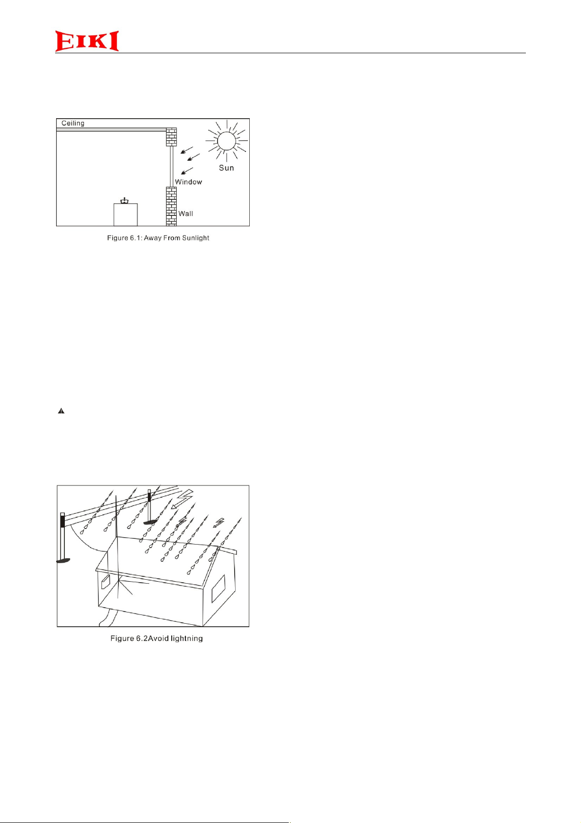
The SH2191heat removal or ventilation is required, Avoid direct sunlight and away from heat (Figure 6.1), avoid
the equipment placed on the vibration desk and to exposure damp, a little snow or rain and dust, it can be placed
on the desktop or plane because of rubber supporting point, or use of special accessories can be installed in
cabinet.
n Connection Warnings:
Before turn on system, please check all connection to ensure that no short circuit. The entire system needs to be
installed under the circuit standard electrical system standards.
Note: cable away from the following places In order to avoid “hum” or interference generated by the
electromagnetic induction:
1. Generate strong electromagnetic field equipment (such as large power transformers)
2.AC power supply wire
3. High-power acoustics wire
CAUTION:
1. Please make sure the voltage values is same with input voltage values, if not, please contact repair center.
2. Connected parts of the input circuit must be connect to ground
3. When Thunder, shut doors and windows; stop to use the equipment, it is best to unplug the power cord, below
conditional circumstance, it will be best to installed arrester, (Figure 6.2)
Page 7
7
Chapter 3: Function.
n 3.1 EMMU02 Host Unit Functionality
2.4G conference microphone system
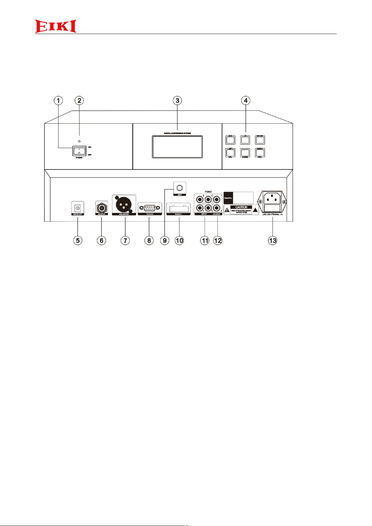
1) ON indicator light
When the machine is turned on, red light
2)Power switch
When the switch is set to the ON position, turn on
the machine
3) Display screen
Display a variety of information and microphone
state
4) Multi-function keys
5) 12V-17V DC power input socket, inside positive,
external negative
6) Mixed audio signal output socket
7) Balanced audio signal output socket
8) Central control machine connecting interface
(RS-232,9600pbs)
9) Antenna cable SMA interface
10) Control camera RS-422 interface,pin3-,pin4+
11) 1-4 video signal input socket
12) Video signal output socket, dual port parallel
output
13) Main power input socket
220V AC input socket
Page 8
8
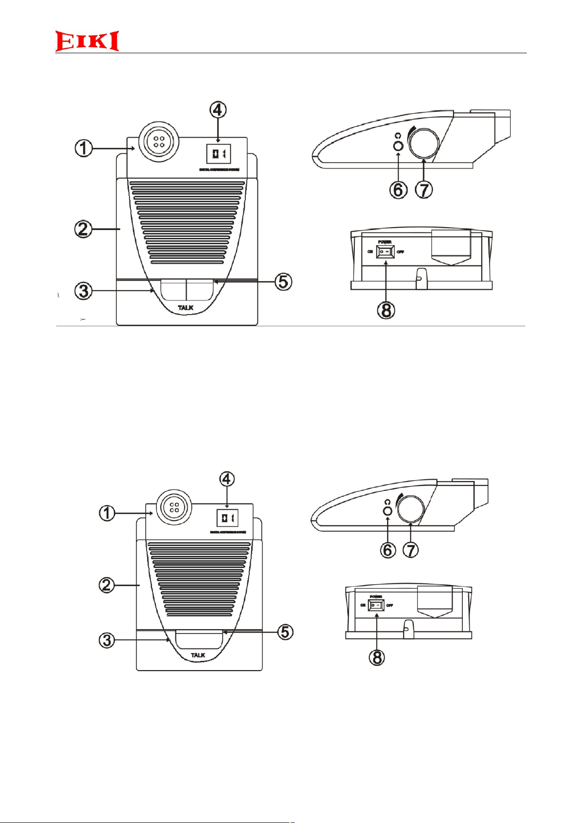
n EMC02 Chairman Microphone Unit Functionality
1) Microphone stem socket
2) Microphone built-in speaker
3) “PROI” bottom,
Priority function, overrides all the active delegate
units
4) "TALK" bottom, start up and shutdown functions
n EMD02Delegate Microphone Unit Functionality
2.4G conference microphone system
5) Display screens to show microphone id
6) Light indicator
7) Headphones port
8) Headphones volume control button
9) Power button
1) Microphone stem socket
2) Microphone built-in speaker
3) "TALK" bottom, start up and shutdown functions
4) Display screens to show microphone address
5) Light indicator
6) Headphones port
7) Headphones volume control button
8) Power button
Page 9

2.4G conference microphone system
9
Chapter 4: System Inventory.
The box designed according to product safety, rationality of the assembly parts. Nice, good safety performance.
Which can be placed on conference microphone unit, rechargeable battery, manual, warranty card, and other
accessories .Conference microphone unit will be good protect in a block of foam, reduces damage in an accident
n Hosts Unit Inventory. (Figure 9.1)
NAME MODEL QUANTITY UNIT
Conference host unit EMMU02 1
host power cord 1
warranty card copy 1
Host instructions 1
n Microphone Unit Inventory (Figure 10.1)
NAME MODEL QUANTITY UNIT
Microphone unit EMC02/EMD02 1
Microphone pole 1
warranty card copy 1
AA rechargeable battery 2
Page 10

2.4G conference microphone system
Mic unit charger
n Note
1.when receipt this product, you should pay attention to check the packaging is intact, packaging case of damage
please check the box whether the product is damaged, if damaged, can be rejected, and please contact the
supplier.
2.the purchase of this product, please carefully check all original accessories are complete, cover the end of the
meeting microphone label on the box label coding, and any discrepancies, please contact supplier.
Mic pole
Warranty card
n Accessory
EM63
Directive Antenna
Connected to the main unit EMMU02 directly, no need
any external power supply.
Transmission range: 30m (Directional)
Installed in the microphone working venue, effective
protection of system stability and management.
Extend line up to 10M.
Dimensions: 410X205X30mm
EM37
Omni directional antenna receiver
Connected to the main unit EMMU02 directly, no need
any external power supply.
Transmission range: 10m (Omni directional)
Installed in the microphone working venue, effective
protection of system stability and management.
Extend line up to 20M.
10
Page 11

2.4G conference microphone system
EM34
Pro-AMP
Connected to the wireless receiver EM37/EM36
directly, no need any external power supply.
The signal amplification, so make the microphone
connection to be more stable
Dimensions: 68.5X51X23mm
EM48
SP33
Charger (charge for 12pcs microphone one time)
Charger (charge 8pcs battery one time)
World -wide voltage adaptable (100-240V)
Charges up to 8pcs AA or 8pcs AAA
Dimensions: 344*224*84(mm)
World -wide voltage adaptable (100-240V)
Dimensions: 150*106(mm)
11
Page 12

2.4G conference microphone system
EM35
NI-MH rechargeable battery
EM35 is Ni-MH AA rechargeable batteries
4 hours charging for saturated time, 30-hour operation
with fully charged battery
Capacity: 2000 mAH
Size: 50.5*14mm
Chapter 5: Installation Guide
n System components. Conference host unit, chairman microphone unit, delegates microphone unit (Figure
12.1).
n System Installation
1.The antenna divided into Omni-directional antenna and directional antenna, base on requirement of different
venues, Do first the first connection now, Omni-directional antenna is suitable for that the conference main unit
and microphone use in one room.
12
Page 13

2.4G conference microphone system
Antenna
2. Now we do the second connection, directional antenna is used when the conferment main unit and the
microphone are in different rooms. Leads directly from the control room to the meeting room, put the antenna
box on the wall (Figure 13.1)
3. Using a special audio cable connect EMMUO2 conference host with amplifier. (Figure 13.2)
13
Page 14

2.4G conference microphone system
Chapter 6: Debugging.
System Connected and installation.
The system has two installation solutions for different conference rooms and limitations of site layout.
1. Do the first connection now, Omni-directional antenna is suitable for that the conference main unit and
microphone use in one room. And it can get the singe 360 degree, generally placed the Omni-directional
antenna in the middle of
the conference
microphone units,
distance of microphone
units and the antenna can
not be greater than 2 m.
14
Page 15

2.4G conference microphone system
2. Now do the second connection, directional antenna is used when the conferment main unit and the
microphone are in different rooms. Leads directly from the control room to the meeting room, put the
antenna box on the wall (Figure 15.2)
Directional antenna is in front of microphone units, range of receiving is 180 degrees horizontally and 38 degree
vertically. General put it up on the wall. Distance of microphone units and the antenna can not be greater than 20
m.
Installation diagram
1. Wall 2. Bracket
3. Screws 4. Antenna
Battery service regulations
Microphone using the standard 14500 battery, you can use 1.5V/2000MAH alkaline batteries, also support
1.2V/2000MAH NI-MH rechargeable batteries, In the case of ordinary alkaline AA batteries, place the red DIP
switch "2" to "ON" position, In the case of NI-MH rechargeable batteries, place the red DIP switch "2"
appropriated "OFF" position, so that the microphone can get reliable power supply properly, note , remove the
battery If you don't use microphone for a long time(have to take out of iron pan)
n Camera connection
Camera communication is RS-485; the communication protocol supports Pelco P, Pelco D, and SONY. Baud rate
is 9600 (not modified), support up to 3 camera balls, and expanded to 8 camera balls by computer, the connection
is tandem connection, if the line did not connect to the device, set connect the 485+ and 485- together by - 120
ohms to prevent signal reflection and interference
please Connect camera ball 485+ to the host unit 485-B Socket, connect 485- to the host unit 485-A, all ball
machine should be consistent with this standard. Panoramic bit of the system default is one ball 63 preset
positions, also modify by the computer.
View the available two-core line view of transmission line, if length of the line more than 100 m, please use
shielded cable, shielded cable connected to the earth wire of ground alternating current, Specifications are as
follows (maximum support distance is 300M)
15
Page 16

2.4G conference microphone system
0-30 m 2 * 0.5 RVVP cable
50-100 m 2 * 1.0 RVVP cable
100-200 m 2 * 1.5 RVVP shielded cable
200-300 m 2 * 2.0 RVVP shielded cable .
connection of video signal
This system can support input signal of the three ball machines, and setup the main output automatically, this
system has a three -way video input, three -way video output, two -way main outputs, the video input of the ball
machine is connected to the No.17 port, No.20 port as the main output, single video signal connect to No.17 port.
Connection of audio signals
This system with one-way non-equilibrium output (No.14 port), one way balance output (No.15 port), one-way
to non-balanced audio output (No.13 port)
n Camera ball preset settings
CDD ADRESS (5) for the 2nd camera ball-tracking microphone start bit,(6) for the 3rd camera ball-tracking
microphone start bit, operation by binary mode, left is the Most Significant Bit, such as (5) 001 010, it is 10
(decimal digit), that is mean the No.2 camera tracking start bit is No.10 microphone. As (6) DIP 001 010. It is 10
(decimal digit). That is mean the No.3 camera tracking start bit is No.20 (sum of 5 and 6) .now. The conference
main setting: the No.1 camera is tracking No.1-No.9 microphone, the No.2 camera is tracking No.10-No.19
microphone, and the No.3 camera is trackingNo.20 microphone to another microphones
Camera ball preset settings
Control by a computer or camera ball equipment, and setup the preset, Match Camera ball preset and the
correspond microphone, For example, tracking the No.1 camera ball to No.1-No.9 microphone, setup No.1
camera corresponding to No.1-No.9 microphone positions; tracking the No.2 camera ball to No.10-No.19
microphone, setup No.2 camera corresponding to No.10-No.19 microphone positions. And so on.
Debugging system
Check the all connected cable in properly, Turn on all the microphones power switch, wait for 10 second, then
turn on the host unit, at that moment, the host unit can star scan how many microphone have been connected, it
will take some time, after scanning is complete, the host display screens “1” position will show the number of
microphone has been connected, the quantity should be consistent as the microphone have been connect. if
not ,please refer to the relevant part of system maintenance
System has to enter the working mode
turn on any microphone when press the “TALK” button, “TALK” indicator and indicator of microphone are red
light, the microphone can be speech.
Speech control
FIFO mode: setup the quantity of delegates (max 4 pcs). If active microphones are over the pre-set quantity, turn
off the first active microphone automatically. Except for VIP microphone, VIP microphone is controlled by itself
and the chairman unit microphone
16
Page 17

2.4G conference microphone system
Priority control
President microphone priority function is turned on, the chairman microphone unit TALK light will be green, at
this moment , all active microphone will turn off automatically, all the Not-chairman microphone can’t turn on
before the chairman shut off, this system can support 4pcs microphone, when we turn on another chairman unit
microphone , they can’t effect each other .
Video automatic tracking
System enables star video-tracking mode by button, the system automatically track to the microphone which turn
on last time,
if the tracking microphone is closed, the camera returned to the last open speech microphone automatically, such
as all the microphone are closed ,camera will return to a panoramic view of the preset position automatically, the
system default panorama preset is 63 preset position of the No.1 Camera .
n Video switching
This system comes with an three in one out automatic video switching system
n Audio output
The main output volume of this system is 600MV
under working state, turn on 4 pcs microphone .open state of the four microphone to speak to the host of the
volume is raised to 20, gradually increase the volume of after-class audio equipment, until the emergence of
acoustic feedback phenomenon, then, the volume of the host received as small as 18, to ensure the stability of the
voice in the meeting,
This system uses a digital feedback suppression technology, pickup distance can be up to 60CM
After audio equipment such as balancing equipment, reasonable adjustments can obtain better results
n System Setup Operating Instructions
(1) System Chinese language interface or English language interface selection:
After the host is power on, the LCD display the following picture
If the arrow points to the ENGLISH, the language of the system (including the host and
microphone units) LCD is set to English.
If the arrow points to the "Chinese", the language of the system (including the host and
microphone units) LCD is set to Chinese.
If you do not do any operation, this state will be maintained for about 10 seconds automatically
into the next state – Welcome interface.
17
Page 18

2.4G conference microphone system
When the host display language selection screen, press the up and down arrow to change the
language, then pressing the "ENTER" button or wait for 10 seconds, the system will enter the next
state - welcome interface.
(2)Welcome interface (Chinese or English)
The welcome screen will be displayed about 5 seconds; the system automatically enters the
standby.
(3)Speech state or standby mode.
The above screen shows the status of the English language interface and the standby, for detail as:
A. "MODE: FIFO". Through the setting, this can be set to the "MODE: FIFO","MODE:
LIMITED", “MODE: LIMITED TIME", "MODE: CHAIRMAN”.
B. Allows up to 4 people at the same time to discuss speech, through the setting, which can be set
to 1,2,3,4.
C. “CH: CH1 CH2 CH3 CH4”, meaning that the following display contents (microphone unit ID
and battery information), respectively, occupy the host channel 1 to 4.
D. “UNIT”, respectively to display the 1-4 channels are connected the microphone ID. The
microphone ID range is 001-999, which means that the channel is not connected to any
microphone. None digit indicates that the channel is not connected to any microphone
E. “CELL:”, displays the remaining capacity of the microphone battery.
(4) The system mode setting
In standby state click the "ENTER" key on the front panel of the host, the LCD “MODE:”area
display is highlighted,
18
Page 19

2.4G conference microphone system
LIMITED" mode, continue to set the hours, minutes, and seconds. As shown below:
Press "LEFT" or "RIGHT" key to set the item, hours, minutes, seconds.
Press the "UP" or "DOWN" button to select the required mode, and then press the "ENTER"
button to determine and save, the system will return to standby mode. If you choose the "TIME
19
Page 20

2.4G conference microphone system
(5) Press "UP" or "DOWN" to adjust the setting item value, and then press the "ENTER" button to
determine and save and the system will return to the standby mode.
In the standby mode, Twice press "ENTER" button on the front panel of the host, the number of
“SPEAK:”area on LCD display content is highlighted.
Press "UP" or "DOWN" key to select the required number of the discuss people, whitch is the
range of 1-4, and then press "ENTER" button to determine and save, the system will return to
standby mode.
(6) Microphone unit setting method.
The setting is to be used for all microphone units in the same meeting place with a host to consist
of a system, and to assign different ID for each units, the process is also called coding. Only the
unit with the host to complete the coding can be join to the system, the unit number can be 1-999.
In a system, the unit ID can not be same. In the standby state, press the "enter" key three times, the
host LCD display setting unit, the character of the unit ID is highlighted
20
Page 21

2.4G conference microphone system
"EXIT" button to return to the standby mode. This setting is shown in the following figure:
Press "UP" key or "DOWN" button to select the unit ID, then to power on the microphone unit,
then press the speech button, about 5 seconds after the completion of the unit to return to the
standby state, the host LCD display "set up to complete" and enter the next unit set up interface. At
this point, you can continue to set the ID for more units,or press the "EXIT" button to exit the
setting state, the system will return to standby mode.
(7) Video communication control protocol settings.
On the host front panel and press the "ENTER" key four times, the LCD display of host video
communication protocol is highlighted, as shown below:
Press "UP" or "DOWN" button to select the camera protocol, then press enter key to determine and
save, the system will enter the four circuit video selection and camera focusing state adjusting
selection interface for each microphone unit. Press "LEFT" or "RIGHT" button to switch between
camera and microphone ID. Press "UP" or "DOWN" button to change camera or microphone ID.
Unit ID "0" corresponding to the main scene. Press "ENTER" button to save settings. Press
21
Page 22

2.4G conference microphone system
(8) Volume adjustment settings.
In the system standby or speech state, directly press the "VOL-" or "VOL+" button to adjust the
volume.
After the volume is set, press the "exit" button or wait for 15 seconds without any action, and the
system will exit the setting state and return to the standby state or the speech state.
22
Page 23

2.4G conference microphone system
Chapter7: System Parameters
n Usual Troubleshooting
Failure Reason Solution
No response when turn on
system controller( Power light is
dark)
system controller can’t edit No
automatically
system controller can’t control
camera
Above information is only for reference. If have other problems, please contact distributor, and request
technique support.
power supply trouble clear
plug is not stable clear
AC fuse is damaged(F3A250V)
Haven’t edit mic’ID No Press unit’s “MIC” key, editing ID
System controller and camera have
different communication protocol、
baud rate.
replacing
No for every mic unit.
Please reset communication
protocol & baud rate of system
controller and camera. Suggest
using PELCO-P 9600.
n Main unit Technical parameters
Model EMMU02
Power Power Eurasia: AC 220 V ~ 240 V 50 Hz (manual selection
required)
Power consumption: Standard: <50 W
Frequency response 80-18000 Hz (3 dB )
SNR >80 dB(A)
Dynamic range >90 dB
Total Harmonic Distortion ≤0.01%
Channel Crosstalk >80 dB
Display 128*64 LCD screen
Ambient temperature and
-20~60/0℃ -95%
humidity
Waterproof anti-rain, dust, salt fog
Supply / consumption 115/230Vac (±5%) – 50/60Hz / 50 VA
Dimensions (L* H* D) 480*268*90 mm
Weight 4KG
23
Page 24

2.4G conference microphone system
n Microphone unit Technical parameters
model EMC02/EMD02
frequency 2421-2475MHz
Pickup distance 30m±5m Use 11 dB antenna in visible distance
Audio output amplitude <0dB 20CM
Frequency response 100Hz-18KHz
THD&SNR ≥80 dB
Power supply
2.4/3V-DC
sensitivity -57dB+-2dB
Chairman unit electric current
Delegate unit electric current
60/86mA+-3mA standby mode / working mode,3V
60/82mA+-3mA standby mode / working mode,3V
24
Page 25

FCC Caution:
This device complies with part 15 of the FCC Rules. Operation is subject to the
following two conditions: (1) This device may not cause harmful interference, and (2)
this device must accept any interference received, including interference that may
cause undesired operation.
Any Changes or modifications not expressly approved by the party responsible for
compliance could void the user's authority to operate the equipment.
Note: This equipment has been tested and found to comply with the limits for a Class
B digital device, pursuant to part 15 of the FCC Rules. These limits are designed to
provide reasonable protection against harmful interference in a residential installation.
This equipment generates uses and can radiate radio frequency energy and, if not
installed and used in accordance with the instructions, may cause harmful interference
to radio communications. However, there is no guarantee that interference will not
occur in a particular installation. If this equipment does cause harmful interference to
radio or television reception, which can be determined by turning the equipment off
and on, the user is encouraged to try to correct the interference by one or more of the
following measures:
-Reorient or relocate the receiving antenna.
-Increase the separation between the equipment and receiver.
-Connect the equipment into an outlet on a circuit different from that to which the
receiver is connected.
-Consult the dealer or an experienced radio/TV technician for help.
The device has been evaluated to meet general RF exposure requirement. The device
can be used in portable exposure condition without restriction.
Page 26

2.4G conference microphone system
Copyright by EIKI
Last revision: 10/2016
25
 Loading...