

Page 1
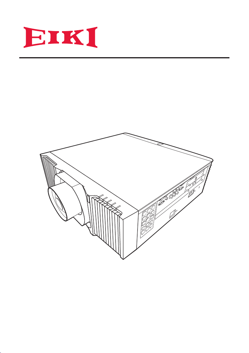
Owner's Manual
Multimedia Projector
EK-830U/EK-831U
■
Read this Owner′s Manual carefully before using the projector, and keep it for
future reference.
■
The pictures for On Screen Display menus and the projector in this guide may
slightly vary from the actual design.
■
The contents of this Owner′s Manual are subject to change without notice.
Page 2

Page 3

Contents
Usage Notice ................................. 4
Safety Information ................................... 4
Safety Labels of This Machine ................ 6
Regulation & Safety Notices .................14
Other Information ..................................18
Introduction ................................. 19
Product Features ................................... 19
Package Overview ................................ 20
Product Overview .................................. 21
Connection Ports .................................... 22
Control Panel .......................................... 23
Remote Control ..................................... 25
Remote Control Battery Installation ........ 28
Remote Control Operating Range .......... 29
Basic Operations ........................ 30
Installing the Projection Lens ................ 30
Removing the Projection Lens .............. 30
Using the Projector in Portrait Mode ..... 31
Connecting the Projector .......................32
Connecting to Computer/Notebook/AV
Equipment/Other Devices ....................... 32
Connecting to HDBaseT Module ............ 33
Powering On/Off the Projector .............. 34
Powering On the Projector ...................... 34
Powering Off the Projector ...................... 35
Adjusting the Projected Image .............. 36
Adjusting the Position of Projector
Image ...................................................... 36
Adjusting the Projector Zoom and
Focus ...................................................... 36
Adjusting the Lens Position ..................... 36
Adjusting Projection Image Size ............. 37
User Settings .............................. 42
Using the On Screen Display (OSD) ..... 42
How to Operate ....................................... 42
Image Adjustment ................................... 43
Display Settings ...................................... 46
Default Settings ....................................... 50
Options .................................................... 53
OSD Menu Tree ....................................55
LAN Control ................................ 58
Wired LAN Terminal Functionalities
..............................................................58
Supported External Devices ................... 58
Controlling this Device with Web
Browser ................................................. 59
Connecting to the Device ........................ 59
Crestron .................................................. 59
Crestron Tools ......................................... 60
Crestron Info ........................................... 60
Troubleshooting .........................61
Appendices ................................. 67
List of Compatible Signals .....................67
Congurations of Terminals ..................67
Terminal: Computer In (Mini D-sub 15 pin)
[Monitor Out] ........................................... 73
Terminal: PC Control (D-sub 9 pin) (male)
................................................................ 73
Terminal: 3D Sync ................................... 74
Terminal: 12V Trigger Out ....................... 74
Terminal: Wired Remote In/Out............... 74
Specications ........................................ 75
Cabinet Dimensions .............................. 76
Trademarks ...........................................77
3
Page 4
Usage Notice
Important Safety Information
Important:
It is strongly recommended that you read this
section carefully before using the projector. These
safety and usage instructions will ensure that you
enjoy many years of safe use of the projector.
Keep this manual for future reference.
Symbols Used
Warning symbols are used on the unit and in this
manual to alert you of hazardous situations. The
following styles are used in this manual to alert you to
important information.
Note:
Provides additional information on the topic at hand.
Important:
Provides additional information that should not be
overlooked.
Caution:
Alerts you to situations that may damage the unit.
Warning:
Alerts you to situations that may damage the unit,
create a hazardous environment, or cause personal
injury.
General Safety Information
¾ Do not open the unit case. Aside from the lter,
there are no user-serviceable parts in the unit. For
servicing, contact qualied service personnel.
¾ Follow all warnings and cautions in this manual and
on the unit case.
¾ This projector has built-in laser module. Hazardous
optical radiation possibly emits from this product. Do
not stare into the beam which may be harmful to the
eyes.
¾ Do not place the unit on an unstable surface, cart,
or stand.
¾ Avoid using the system near water, in direct
sunlight, or near a heating device.
¾ Do not place heavy objects such as books or bags
on the unit.
Safety Instructions
• Please read this manual completely before installing
and operating the projector.
• The projector provides many convenient features
and functions. Proper operation may enable you
to fully utilize the features and keep it in good
condition. Otherwise, it will not only shorten
the service life of the unit, but also may cause
malfunction, a re, or other accidents.
• If your projector cannot work properly, please read
this manual again, check the operating methods and
cable connection, and try the solutions in the part of
Troubleshooting. If the problem still exists, contact
the dealer or the service center.
Caution:
ELECTRIC SHOCK DO NOT OPEN
Caution:
To reduce the risk of electric shock, do not remove
cover (or back), no user serviceable parts inside
except lamp replacement. Refer servicing to
qualied service personnel.
This symbol indicates that dangerous
voltage constituting a risk of electric shock
is present within this unit.
This symbol indicates that there are
important operating and maintenance
instructions in the user’s manual with this
unit.
FOR EU USERS
The symbol mark and recycling systems described
below apply to EU countries and do not apply to
countries in other areas of the world.
Your product is designed and manufactured with
high quality materials and components which can
be recycled and/or reused. The symbol mark means
that electrical and electronic equipment, batteries
and accumulators, at their end-of-life, should be
disposed of separately from your household waste.
Note:
If a chemical symbol is printed beneath the symbol
mark, this chemical symbol means that the battery
or accumulator contains a heavy metal at a certain
concentration. This will be indicated as follows:
Hg: mercury, Cd: cadmium, Pb: lead
In the European Union there are
separate collection systems for used
electrical and electronic equipment,
batteries and accumulators.
Please, dispose of them correctly
at your local community waste
collection/recycling centre.
Please help us to conserve the environment we live
in!
Safety Precautions
Caution:
• The projector must be grounded.
• Do not expose the projector to raindrops or high
humidity to avoid a re or electric shock.
• This projector produces intense light from the
projection lens. Avoid staring directly into the
lens, otherwise eye damage could be caused. Be
especially careful that children do not stare directly
into the beam.
4
Page 5
Usage Notice
• Place the projector in a proper position. Otherwise it
may result in re hazard.
• Leave an appropriate space from the top, sides, and
back of the shell in order to ventilate and cool down
the projector. See Owner’s manual for the minimum
distance to be left each side. It must be satised if
the projector is placed in sealed environment like a
cabinet.
• Do not cover the vent of the projector. Poor radiation
may shorten the service life or even cause dangers.
• Remove the AC power plug if the projector is not to
be used for a long time.
• Do not set the projector in greasy, wet, or smoky
conditions such as in a kitchen, to prevent a
malfunction or accident. If the projector comes
in contact with oil or chemicals, it may become
deteriorated.
• Read and keep this manual for future reference.
• The mains plug/appliance coupler is used as
disconnect device, the disconnect device shall
remain readily operable.
Safety Guide
• Read all of the instructions given here and retain
them for later use. Unplug this projector from AC
power supply before cleaning. Do not use liquid or
aerosol cleaners.
• Use a damp cloth for cleaning.
• Follow all warnings and instructions marked on the
projector.
• For added protection to the projector during a
lightning storm, or when it is left unattended and
unused for long periods of time, unplug it from the
wall outlet. This will prevent damage due to lightning
and power line surges.
• Do not expose this unit to rain or use near water...
for example, in a wet basement, near a swimming
pool, etc...
• Do not use attachments not recommended by the
manufacturer as they may cause hazards.
• Do not place this projector on an unstable
cart, stand, or table. The projector
may fall, causing serious
injury to a child or an adult,
and serious damage to the projector.
• Use only with a cart or stand
recommended by the manufacturer, or sold with
the projector. Wall or shelf mounting should follow
the manufacturer’s instructions, and should use a
mounting kit approved by the manufacturers.
> 0 cm
(> 0”)
Caution:
> 50 cm
(> 19.7”)
> 50 cm
(> 19.7”)
> 30 cm
(> 11.8”)
> 0 cm
(> 0”)
• An appliance and cart combination should be
moved with care. Quick stops, excessive force, and
uneven surfaces may cause the appliance and cart
combination to overturn.
• Slots and openings in the back and bottom of
the cabinet are provided for ventilation, to ensure
reliable operation of the equipment and to protect it
from overheating.
• The openings should never be covered with cloth or
other materials, and the bottom opening should not
be blocked by placing the projector on a bed, sofa,
rug, or other similar surface. This projector should
never be placed near or over a radiator or heat
register.
• This projector should not be placed in a buildin installation such as a book case unless proper
ventilation is provided.
• Never push objects of any kind into this projector
through cabinet slots as they may touch dangerous
voltage points or short out parts that could result in
a re or electric shock. Never spill liquid of any kind
on the projector.
• Do not install the projector near the ventilation duct
of air-conditioning equipment.
• This projector should be operated only from the type
of power source indicat-ed on the marking label.
• If you are not sure of the type of power supplied,
consult your authorized dealer or local power
company.
• Do not overload wall outlets and extension cords as
this can result in re or electric shock. Do not allow
anything to rest on the power cord. Do not locate
this projector where the cord may be damaged by
persons walking on it.
• Do not attempt to service this projector yourself
as opening or removing Covers may expose you
to dangerous voltage or other hazards. Refer all
servicing to qualied service personnel.
¾ Unplug this projector from wall outlet and refer
servicing to qualied service personnel under the
following conditions:
¾ When the power cord or plug is damaged or
frayed.
¾ If liquid has been spilled into the projector.
¾ If the projector has been exposed to rain or water.
¾ If the projector does not operate normally by
following the operating instructions. Adjust only
those controls that are covered by the operating
instructions as improper adjustment of other
controls may result in damage and will often
require extensive work by a qualied technician to
restore the projector to normal operation.
¾ If the projector has been dropped or the cabinet
has been damaged.
• When the projector exhibits a distinct change in
performance - this indicates a need for service.
• When replacement parts are required, be sure the
service technician has used replacement parts
specied by the manufacturer that have the same
characteristics as the original part. Unauthorized
substitutions may result in re, electric shock, or
injury to persons.
5
Page 6
Usage Notice
Usage Notice
• Upon completion of any service or repairs to this
projector, ask the service technician to perform
routine safety checks to determine that the projector
is in safe operating condition.
Information for users in the European Union
This is a device to project images onto a screen,
etc., and is not intended for use as indoor lighting in
a domestic environment. Directive 2009/125/EC.
Warning:
Do not aim a laser pointer at the lens apearture,
which may damage the DMD in the projector and
cause personal injury.
We are not responsible for the hurt and damage
caused by the improper use of laser pointer even in
warranty periond.
Air circulation
Vents in the cabinet are provided for ventilation. To
ensure reliable operation of the product and to protect
it from overheating, these openings must not be
blocked or covered.
Caution:
• Hot air is exhausted from the exhaust vent. When
using or installing the projector, the following
precautions should be taken.
• Do not put any ammable objects, or spray can
near the projector. Hot air is exhausted from the
air vents.
• Keep the exhaust vent at least 1m away from any
objects.
• Do not touch a peripheral part of the exhaust vent,
especially screws and metallic part. This area will
become hot while the projector is being used.
• Do not put anything on the projector. Objects put
on the cabinet will not only get damaged but also
may cause re hazard by heat.
• Cooling fans are provided to cool down the
projector.
• The fan’s running speed is changed according to
the temperature inside the projector.
Moving the projector
When moving the projector, take care of the lens and
retract the adjustable foot to prevent damage to the
lens and cabinet.
For information about transporting the projector
by courier or any other transport service, consult
your dealer.
• Do not put the projector in a case before it is
cooled enough.
Caution in ceiling installation the
projector
• Only qualied personal is authorized for ceiling
installation.
• We are not responsible for the hurt and damage
caused by ceiling brakect that purchased from
unauthorized dealer even in warranty period.
• Remove the ceiling bracket immediately while not
use.
• While installing, torque screwdriver is suggested,
don’t use electric or impact-type screwdriver.
• Please read the manual of bracket for details.
• Please read the Owner ’s Manual, and conrm
screw size and location of screw holes on the
projector
• The bracket is subject to change without notice.
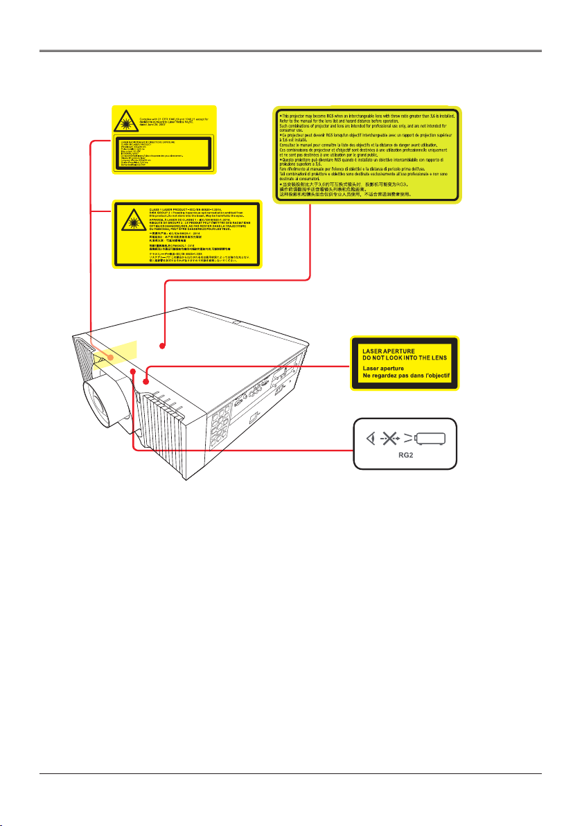
Safety Labels of This machine
Laser Notice
<For USA and Canada>
This Product is classied as Class 3R of IEC608251:2007 and also complies with 21 CFR 1040.10 and
1040.11 except for deviations pursuant to Laser Notice
No.50, dated June 24, 2007.
<For EU countries, Japan, and China>
IEC 60825-1:2014: CLASS 1 LASER PRODUCT RISK GROUP 2
Wavelength:
449-461 nm
Pulse duration:
1.66 ms
Max. output:
98 mW
Laser emission
port
Caution in moving or transporting the
projector
• Do not drop or bump the projector, otherwise
damages or malfunctions may result.
• When carrying the projector, use a suitable
carrying case.
• Do not transport the projector by courier or any
other transport service in an unsuitable transport
case. This may cause damage to the projector.
6
Page 7
Usage Notice
1. Do not look into the lens while the light source
is on. The strong light from the light source
may cause damage to your eyesight. RG2 IEC
62471-5:2015
2. Do not place anything in front of the lens while
the projector is operating. Things placed in front
of the lens may overheat and burn or start a
re. If you want to temporarily stop the projected
image, use the Blank key on the remote control.
3. Do not remove any screws. Do not block or
cover the vents.
4. Do not look into the lens. (For USA and Canada
only).
5. Laser aperture warning: (For USA and Canada
only).
• CLASS 3R LASER PRODUCT-AVOID DIRECT
EYE EXPOSURE
• Do not look into the light source using optical
instruments (such as magnifying glasses and
mirrors). Visual impairment could result.
• When turning on the projector, make sure no
one within projection range is looking at the
lens.
• Keep any items (magnifying glass etc.) out of
the light path of the projector. The light path
being projected from the lens is extensive,
therefore any kind of abnormal objects that can
redirect light coming out of the lens, can cause
an unpredictable outcome such as a re or
injury to the eyes.
6. Laser aperture warning: (For other countries).
• CLASS 1 LASER PRODUCT - RISK GROUP 2
• Do not stare into the beam, maybe harmful to
the eyes.
7. Risk group 3: (Except USA and Canada)
This projector may become RG3 when an
interchangeable lens with throw ratio greater
than the number stated on the label.
• As with any bright light source, do not stare into
the beam. RG2 IEC 62471-5:2015
• No direct exposure to the beam shall be
permitted. RG3 IEC 62471-5:2015
• Operators shall control access to the beam
within the hazard distance or install the product
at the height that will prevent spectators’ eyes
from being in the hazard distance.
• Hazard distance
RG2
RG2
AH-AC25020
Lens Type R0
AH-AC22060
Lens Type R1
AH-AC22070
Lens Type R2
AH-AC21020
Lens Type R3
AH-AC24020
Lens Type R4
AH-AC23020
Lens Type R5
AH-AC23030
Lens Type R6
RG3
Hazard distance
RG3
Description
Ultra Short
Throw Lens
Ultra Short
Throw Zoom
Lens
Short Throw
Zoom Lens
Standard
Zoom Lens
Middle
Throw Zoom
Lens
Long Throw
Zoom Lens
Ultra Long
Throw Zoom
Lens
Throw
Hazard
Ratio
Distance
0.377 NA RG2
0.76–0.95 NA RG2
1.14–1.71 NA RG2
1.61–2.42 NA RG2
2.37–3.60 NA RG2
3.53–5.65 1550 mm RG3
5.52–8.83 1370 mm RG3
• Cinema projectors that have a hazard
distance greater than 1 m and emit light into
an uncontrolled area where persons may be
present should be positioned in accordance
with “the xed projector installation” parameters,
resulting in a hazard distance that does not
extend into the audience area unless the beam
is at least 2 m above the oor level.
• In non-cinema, environments where
unrestrained behavior is reasonably
foreseeable, the minimum separation height
should be greater than or equal to 3.0 m to
prevent potential exposure, for example by
an individual sitting on another individual’s
shoulders, within the hazard distance. For
example, a sufciently large separation height
may be achieved by mounting the projector
on the ceiling or through the use of physical
barriers.
IEC624715:2015
7
Page 8
Safety Labels
Usage Notice
Usage Notice
8
Page 9
Usage Notice
Compliance
FCC Caution
Note: This equipment has been tested and found
to comply with the limits for a Class* digital device,
pursuant to Part 15 of the FCC Rules. These limits
are designed to provide reasonable protection against
harmful interference in a residential installation. This
equipment generates, uses, and can radiate radio
frequency energy, and if not installed and used in
accordance with the instructions, may cause harmful
interference to radio communications. However, there
is no guarantee that interference will not occur in a
particular installation. If this equipment does cause
harmful interference to radio or television reception,
which can be determined by turning the equipment
off and on, the user is encouraged to try to correct
the interference by one or more of the following
measures:
• Reorient or relocate the receiving antenna.
• Increase the separation between the equipment and
receiver.
• Connect the equipment into an outlet on a circuit
different from that to which the receiver is connected.
• Consult the dealer or an experienced radio/TV
technician for help
Use of shielded cable is required to comply with
Class* limits in Subpart B of Part 15 of FCC Rules.
* See the rating label on the projector if class A or B.
Do not make any changes or modications to
the equipment unless otherwise specied in the
instructions. If such changes or modications should
be made, you could be required to stop operation of
the equipment.
Trade Name : EIKI
Responsible party : EIKI International, Inc.
Address : 30251 Esperanza Rancho Santa Margarita
CA 92688-2132
Telephone No. : 800-242-3454 (949-457-0200)
Canadian Radio Interference Regulations:
This digital appraratus meets all requirements of
the Canadian ICES-003.
* See the rating label on the projector if class A or B.
AC Power Cord Requirement
The AC Power Cord supplied with this projector meets
the requirement for use in the country you purchased
it.
AC Power Cord for the United States and Canada:
AC Power Cord used in the United States and Canada
is listed by the Under-writers Laboratories (UL) and
certied by the Canadian Standard Association (CSA).
AC Power Cord for the United Kingdom:
This cord is already tted with a moulded plug
incorporating a fuse, the value of which is indicated
on the pin face of the plug. Should the fuse need to
be replaced, an ASTA approved BS 1362 fuse must
be used of the same rating, marked thus . If the
fuse cover is detachable, never use the plug with the
cover omitted. If a replacement fuse cover is required,
ensure it is of the same colour as that visible on the
pin face of the plug (i.e. red or orange). Fuse covers
are available from the Parts Department indicated in
your User Instructions.
If the plug supplied is not suitable for your socket
outlet, it should be cut off and destroyed. The end of
the exible cord should be suitably prepared and the
correct plug tted.
Warning:
A plug with bared exible cord is hazardous if
engaged in a live socket outlet.
The Wires in this mains lead are coloured in
accordance with the following code:
• Green-and-yellow ......... Earth
• Blue .............................. Neutral
• Brown ........................... Live
As the colours of the wires in the mains lead of this
apparatus may not correspond with the coloured
markings identifying the terminals in your plug
proceed as follows:
• The wire which is coloured green-and-yellow must
be connected to the terminal in the plug which is
marked by the letter E or by the safety earth symbol
or coloured green or green-and-yellow.
• The wire which is coloured blue must be connected
to the terminal which is marked with the letter N or
coloured black.
• The wire which is coloured brown must be
connected to the terminal which is marked with the
letter L or coloured red.
Warning:
This apparatus must be earthed.
The socket-outlet should be installed near the
equipment and easily accessible.
AC Power Cord has a grounding-type AC line
plug.
This is a safety feature to be sure that the plug will t
into the power outlet. Do not try to defeat this safety
feature. Should you be unable to insert the plug into
the outlet, contact your electrician.
9
Page 10
Usage Notice
ABOUT THE LASER LIGHT SOURCE
Warning-
■
Caution-
■
Caution-
■
Caution-
■
Caution-
■
Do not look into the lens or vent when the product
is on. The bright light may damage your eyes. Be
especially careful in an environment with children.
This projector has built-in laser module. Hazardous
optical radiation possibly emits from this product. Do
not stare into the beam which may be harmful to the
eyes.
Use of controls or adjustments or performance of
procedures other than those specied herein may
result in hazardous radiation exposure.
Do not block the projection light when it is on. If you
do so, the part that is blocking the projection light
may get quite hot and deform, deteriorate or cause
a burn or re. The reected light may make the
lens hot and cause a product failure. To temporarily
suspend projection, select the Blank function. To
suspend longer, turn off the product.
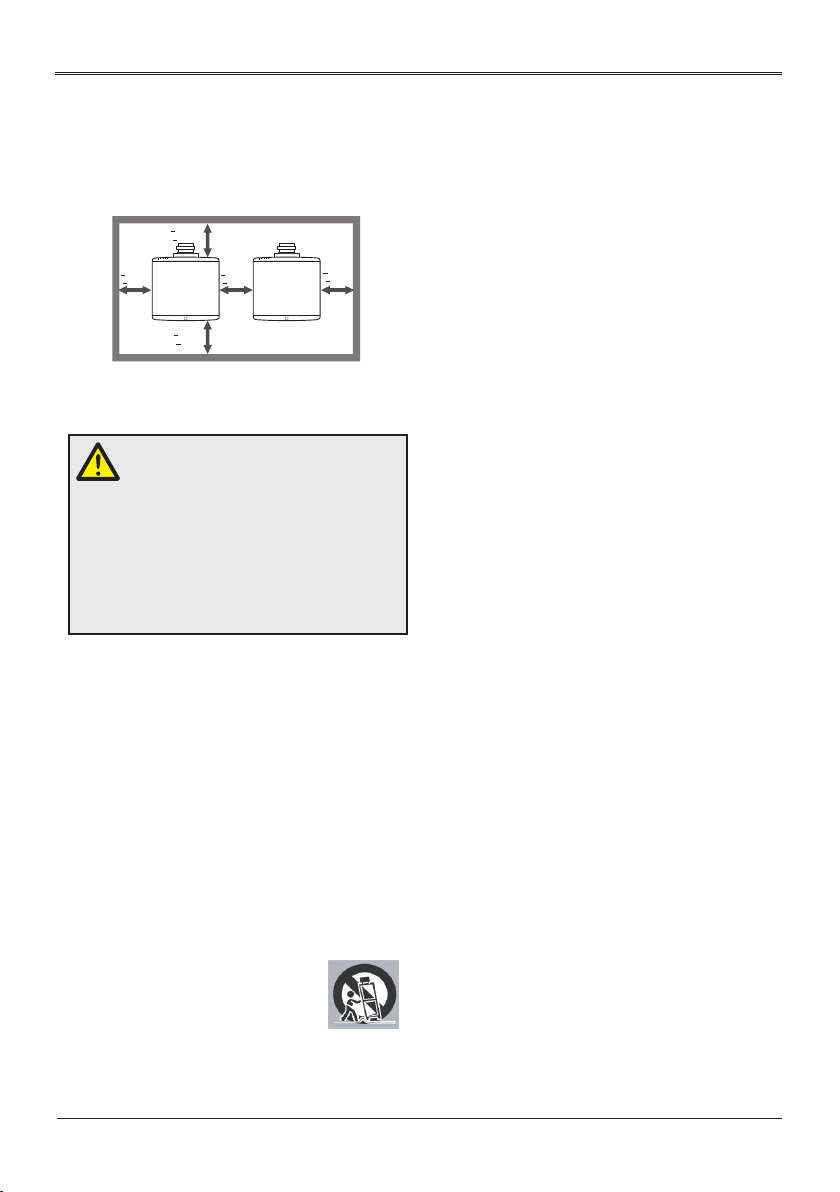
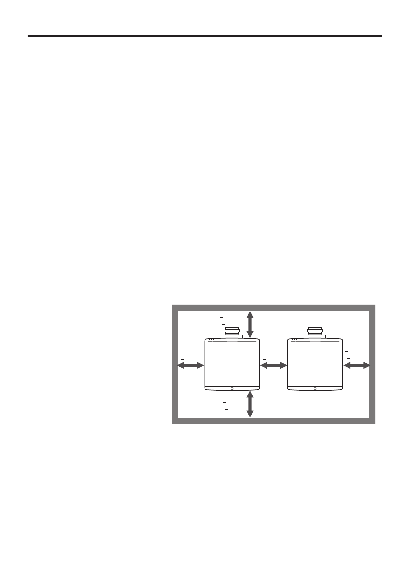
Leave 30 cm or over space between the projectors
when projectors are installed side by side.
> 50 cm
(> 19.7”)
10
> 0 cm
(> 0”)
> 50 cm
(> 19.7”)
> 30 cm
(> 11.8”)
> 0 cm
(> 0”)
Page 11
Caution-
■
Usage Notice
For 360° installation, install the projector more than
50 cm away from the wall or the oor. When the
air intake and discharge outlet are obstructed, the
temperature inside the projector will rise and this
may result in a malfunction.
> 50 cm
(> 19.7”)
Caution-
■
> 0 cm
(> 0”)
> 50 cm
(> 19.7”)
> 0 cm
(> 0”)
When installing the projector on the right side, leave
a space of at least 50 cm between the exhaust vent
and the wall and a space of at least 50 cm for the
intake vent.
> 0 cm
(> 0”)
> 50 cm
Wall
(> 19.7”)
Floor
> 0 cm
(> 0”)
> 50 cm
(> 19.7”)
11
Page 12
Caution-
■
Usage Notice
When installing the projector on the left side, leave
a space of at least 50 cm between the exhaust vent
and the wall and a space of at least 50 cm for the
intake vent.
> 0 cm
(> 0”)
Caution-
■
> 50 cm
(> 19.7”)
> 0 cm
(> 0”)
> 50 cm
(> 19.7”)
Floor
Wall
Do not pile up more than 3 projectors.
12
Page 13

Usage Notice
REMOTE CONTROL BATTERY
Warning
• Never throw batteries into a re.
Using the batteries improperly may cause them to explode or leak
and may result in serious injury. If battery-leaking uid contacts skin,
wash the uid off immediately with clean water and consult a doctor.
If the uid spills on an instrument, avoid contact and wipe it off using
tissue paper. Then dispose of the used tissue paper as ammable
garbage after moistening the tissue with water.
• Keep new and used batteries away from children.
If the battery compartment does not close securely, stop using the
product and keep it away from children. If you think batteries might
have been swallowed or placed inside any part of the body, seek
immediate medical attention.
Notes
• Use the recommended battery type.
• Dispose of batteries in a designated disposal area.
• Attention should be drawn to the environmental aspects of battery
disposal.
• If the remote control does not operate correctly, or if the operating
range becomes reduced, replace the batteries.
• Avoid contact with water or liquid.
• Do not expose the remote control to moisture or heat.
• Do not drop the remote control.
• If the batteries have leaked in the remote control, carefully wipe
the case clean and install new batteries.
• Dispose of used batteries according to the instructions.
• The remote control may fail to operate if the infrared remote sensor
is exposed to bright sunlight or uorescent lighting.
Important:
Contents of this manual are subject to change without prior notice. In no
event will the company be liable for direct, indirect, special, incidental, or
consequential damages as a result of handing or operating this product.
13
Page 14

Usage Notice
Regulation & Safety Notices
This appendix lists the general notices of your Projector.
Notice: Users in the United States of
America FCC notice
MODEL NAME: EK-830 series
TRADE NAME: EIKI
MODEL NAME: EK-830 series
Tested To Comply With FCC Standards
FOR COMMERCIAL OR OFFICE USE
This device complies with Part 15 of the FCC Rules. Operation is
subject to the following two conditions:
1. This device may not cause harmful interference and
2. This device must accept any interference received, including
interference that may cause undesired operation.
This equipment has been tested and found to comply with the limits
for a Class A digital device, pursuant to Part 15 of the FCC Rules.
These limits are designed to provide reasonable protection against
harmful interference when the equipment is operated in a commercial
environment. This equipment generates, uses, and can radiate radio
frequency energy and, if not installed and used in accordance with
the instruction manual, may cause harmful interference to radio
communications. Operation of this equipment in a residential area
is likely to cause harmful interference in which case the user will be
required to correct the interference at his own expense.
Caution: Changes or modications not expressly approved by the
party responsible for compliance could void the user’s authority to
operate the equipment.
RESPONSIBLE PARTY: EIKI International, Inc.
30251 Esperanza Rancho Santa Margarita CA 92688-2132
Phone: 800-242-3454 (949-457-0200)
14
Page 15

Usage Notice
Notice: Shielded cables
All connections to other computing devices must be made using
shielded cables to maintain compliance with FCC regulations.
Caution
Changes or modications not expressly approved by the
manufacturer could void the user’s authority, which is granted by the
Federal Communications Commission, to operate this projector.
Notes to Users in the State of California
Perchlorate Material - special handling may apply. See www.dtsc.
ca.gov/hazardouswaste/perchlorate.
Declaration of Conformity for EU
countries
■EMC Directive 2014/30/EU (including amendments)
■Low Voltage Directive 2014/35/EU
Warning
This equipment is compliant with Class A of CISPR 32. In a residential
environment this equipment may cause radio interference.
Notice: Users in EU countries
CE Marking Traceability Information (For
EU Countries Only)
15
Page 16
Usage Notice
User Information on Electrical and
Electronic Equipment
Users in the countries where this symbol shown in this section has
been specied in national law on collection and treatment of E-waste.
Our Products contain high quality components and are designed to
facilitate recycling. Our products or product packaging are marked
with the symbol below.
This product contains substances which are harmful to humans and
the environment.
The symbol indicates that the product must not be treated as
municipal waste. It must be disposed of separately via the appropriate
return and collection systems available. By following these
instructions you ensure that this product is treated correctly and help
to reduce potential impacts on the environment and human health,
which could otherwise result from inappropriate handling.
Recycling of products helps to conserve natural resources and protect
the environment.
For more detailed information on collection and recycling systems for
this product, please contact the shop where you purchased it, your
local dealer or sales/service representatives.
16
Notice: Users in Turkey
AEEE Yönetmeliğine Uygundur.
Bu sistem sarf malzemeleri ve yedek parçaları da dahil olmak üzere
AEEE Yönetmeliğine Uygundur.
Page 17

Usage Notice
Notice: Users in the EU
Note for the Battery and/or Accumulator
Symbol
In accordance with the Battery Directive 2006/66/EC Article 20
Information for end-users Annex II, the above symbol is printed on
batteries and accumulators. This symbol means that in the European
Union, used batteries and accumulators should be disposed of
separately from your household waste. In the EU, there are separate
collection systems for not only used electrical and electronic products
but also batteries and accumulators. Please dispose of them correctly
at your local community waste collection/recycling centre.
17
Page 18

Usage Notice
Other Information
Copyrights to Images
When projecting images using the projector, be careful not to infringe
the copyright of protected materials.
The following are examples that may infringe the copyright of
protected materials.
• Broadcasting images or movies for commercial purposes
• Modifying images or movies using functions such as freeze,
magnify, or zoom to broadcast images for commercial purposes or
public viewing
• Varying the aspect ratio of images or movies using a function
that changes the screen size to broadcast images for commercial
purposes or public viewing
Note to Users Viewing 3D Images
Pay attention to the following points when viewing images using 3D
glasses with projector:
• How 3D images are viewed may vary according to the individual.
• Do not use 3D glasses for viewing any material other than 3D
images.
• Before viewing 3D images, make sure to read the manuals
provided with your 3D glasses and 3D compatible content.
• Avoid viewing 3D images for a long period of time. Take a break of
15 minutes or longer after every hour of viewing.
• If you feel sick while viewing 3D images, stop viewing them. If you
continue to feel sick, consult a doctor.
• When viewing 3D image in a room where LED lighting system or
uorescent lights are used, you may feel that the light in the room
ickers. If this is the case, dim the lights until you do not notice any
ickers, or turn off the lights.
• If you or any member of your family has a history of lightsensitive
seizures, consult a doctor before viewing 3D images.
18
Page 19

Introduction
Introduction
Product Features
Outstanding features include:
■Native 1920 x 1200 WUXGA resolution with Auto/4:3/16:9/16:10/1.
88:1/2.35:1 aspect ratio supported
■3D function with Blu-Ray 3D supported for projecting 3D content
using DLP Link Technology
■High brightness and contrast ratio
■Various picture modes
■NTSC/PAL/SECAM and HDTV (720p, 1080i, 1080p) compatibility
■Economy (ECO) mode for extending light source life
■Advanced keystone correction for delivering optimum presentations
■User friendly multilingual On Screen Display
■Extensive lens options with motorized focus/zoom and motorized
lens shift functions
■LAN function for remote management on the projectors from a web
browser
■Compatibility with PJ-Link, Crestron, AMX, and Extron
■Compatibility with 3D VESA standards
19
Page 20
Introduction
Package Overview
This projector comes with all the items shown below. Check to
make sure your unit is complete. Contact your dealer immediately if
anything is missing
.
ON
OFF
(Projection Lens is optional)
Input
Projector Remote Control (with Batteries)
Quick Start Guide Power Cord (EU and US type)
Safety Information VGA cable
20
Page 21
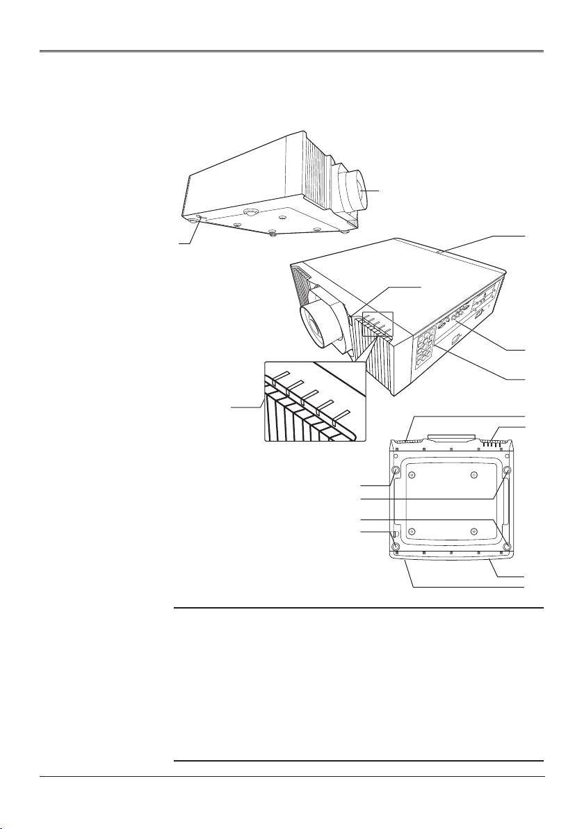
Introduction
Product Overview
2
1
4
1. Security bar
2. Projection lens (optional)
3. IR sensor
4. LED Indicator
5. Connection ports
6. Control panel
7. Intake vent
8. Exhaust vent
9. Adjustable foot
3
3
5
6
7
7
9
9
9
9
8
7
21
Page 22
Introduction
17
17
t
e
Connection Ports
1 2 3 87 9 10 11 12 13 144 65 1516
N
o
• The interface is
subject to model’s
specications.
• Compatible with
MHL version
2, the charging
power 5V@0.9A.
• To use this
feature, you
must plug in the
power adapter/
cable/cord before
turn on/off the
projector.
• Do not use this
jack for anythin
other than
intended use.
18
1. Wired remote control In terminal
Wired remote control Out terminal
2. PC-Control (In) terminal
3. PC-Control (Out) terminal
4. S-Video In terminal
5. Video In terminal
6. Computer2 In terminal
7. Computer1 In terminal
8. Monitor Out terminal
9. HDMI 1/MHL terminal
10. DVI-D In terminal
11. Service terminal
12. USB-A terminal (5V 1.5A Out)
13. LAN terminal
14. 3D sync terminal (In/Out)
15. HDBaseT terminal / Optional slot *
16. 3G-SDI terminal (In/Out) / Optional slot *
17. Adjustable feet
18. AC In socket
19. 12V Trigger Out terminals
20. Anti-theft lock hole (Kensington™ lock)
19
20
Warning:
As a safety precaution, disconnect all power to the projector and
connecting devices before making connections.
22
Page 23
Introduction
14
Control Panel
1
2
4
5
3
7
6
6
6
6
8
10
11
9
12
15
13
1 Power Toggles the projector between standby
mode and on.
2 Test Pattern Display the test pattern.
3 Light Turn on or off the backlight of the control
panel.
4 Menu Press “Menu” to launch the on screen
display (OSD), or close the OSD menu.
5 Enter Select or conrm settings.
6 Four Directional
Select Keys
7 Input Press “Input” to choose your desired input
8 Exit Cancel the selection, or go back to a
9 Auto Set Automatically synchronize the projector to
10 Lens Shift Press “Lens Shift” and the indicator below
Use , , , or to select items or
make adjustments to your selection.
source.
previous page.
the input source.
lights up. Use , , , or to shift the
projection lens.
23
Page 24

Introduction
11 Focus Press “Focus” and the indicator below lights
up. Use , , , or to adjust the
focus setting.
12 Zoom Press “Zoom” and the indicator below lights
up. Use , , , or to adjust the
zoom setting.
13 Indicator light for
“Lens Shift”
14 Indicator light for
“Focus”
15 Indicator light for
“Zoom”
The indicator lights up when “Lens Shift” is
pressed.
The indicator lights up when “Focus” is
pressed.
The indicator lights up when “Zoom” is
pressed.
24
Page 25

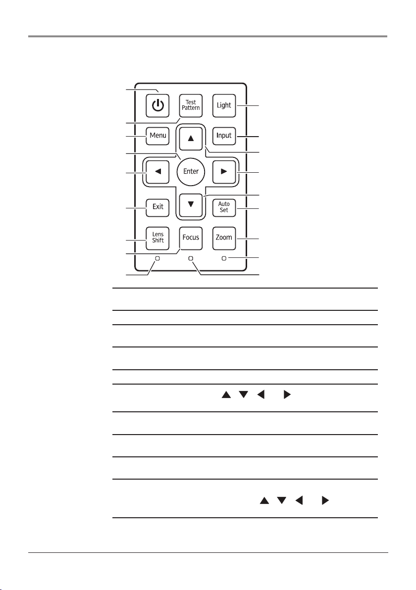
Introduction
Remote Control
ON
1
3
4
6
7
9
10
11
12
14
15
13
17
18
20
21
23
24
27
30
33
OFF
Input
2
5
8
13
16
19
22
25
26
29
28
32
31
1
2
3 Video
4 COMP.1
5 HDMI 1
Turn the projector on.
Turn the projector off
Press “Video” to choose between Video In and
S-Video In terminal.
Press “Comp.1” to choose Computer1 In terminal.
Press “HDMI 1” to choose between HDMI1/MHL
In and HDMI2 In terminal.
25
Page 26

Introduction
6 COMP.2 Press “Comp.2” to choose Computer2 In terminal.
7 S-Video Press “S-Video” to choose S-Video terminal.
8 DVI-D
Four
9
Directional
Select Keys
10 Enter
11 Keystone Display the Keystone correction menu.
12
Menu
13 Exit Cancel the selection, or go back to previous page.
14 Lens Shift
15 Zoom
16 Focus
17 Picture Select the preset picture mode.
18 Test Display the test pattern.
19 Blank Hide the screen image.
20 Freeze
21 Aspect
22 Eco / 0
23 Set
24 INFO Display the current projector related information.
Press “DVI-D” to choose DVI-D In terminal.
Use , , , or to select items or make
adjustments to your selection.
Conrm your section of items in sub menu
operation.
Press “Menu” to launch the on screen display
(OSD), or close the OSD menu.
Press “Lens Shift” and use , , , or to
shift the projection lens.
Press “Zoom” and use , , , or to adjust
the zoom setting.
Press “Focus” and use , , , or to adjust
the focus setting.
Pause the screen image. Press again to resume
the screen image.
Use this function to choose your desired aspect
ratio.
Dim the projector light source which will lower
power consumption and extend the light source
life. / Input numbers.
Set the code for this remote control. Press and
hold “Set”, and then press a number (01, 02,
03...99) to designate an ID. You can control
projector with the matching ID set in the “Options”
> “Control” > “Projector ID” OSD.
Press and hold ”Set” and press “0” twice to cancel
the remote control code.
26
25 Lens Lock Display the Lens Lock menu.
Page 27

Introduction
26 Lens Display the Lens menu.
27 Network Display the Network menu.
28 HSG
29
Language
30
Security Display the Security menu.
31 3D Display the 3D menu.
32 Source Display the Input Source menu.
Number
33
(1~9)
Display the HSG menu.
Display the OSD language selection menu.
Input numbers.
27
Page 28

Introduction
3
Remote Control Battery Installation
Press and slide open the
1
battery cover as
illustrated.
To ensure safe operation, please observe the following precautions :
■Use AAA type batteries.
■Avoid contact with water or liquid.
■Do not expose the remote control to moisture or heat.
■Do not drop the remote control.
■If the battery has leaked in the remote control, carefully wipe the case clean and
install new batteries.
■Risk of an explosion if batteries are replaced by an incorrect type.
■Dispose of used batteries according to local ordinance regulations.
■Remove batteries from remote control when not using for extended periods.
■The remote control may fail to operate if the infrared remote sensor is exposed to
bright sunlight or uorescent lighting.
Install new batteries
2
(AAA). Ensure that you
have the batteries’ polarity
(+/–) aligned correctly.
Close the battery cover
and press it down until it
clicks into place. Do not
mix different types of
batteries or new and old
batteries.
28
Page 29

Introduction
Remote Control Operating Range
Point the remote control toward the projector (Remote Receiver)
when pressing any button.
Maximum operating range for the remote control is about 23.0’
(7m) and ±30° (horizontally), ±20° (vertically) in front and top of the
projector.
23.0’ (7m)
±30° (horizontally),
±20° (vertically)
23.0’ (7m)
±30° (horizontally),
±20° (vertically)
29
Page 30

Basic Operations
2
3
3
1
e
t
e
Basic Operations
Installing the Projection Lens
N
t
o
• Use Optional
Lens AHAC22060/AHAC22070/AHAC21020/AHAC24020/AHAC23020/AHAC23030.
N
o
• For installing
Optional Lens
AH-AC25020,
refer to the
user manual
that packed
with the lens.
1. Remove the front lens cap and rear lens cap from the optional
lens.
2. Remove the dust cap and upper lens cover from the projector.
3. Insert the projection lens.
4. Turn the lever counterclockwise until you feel it click into place to
lock the lens in position.
5. Install the upper lens cover back by push down left and right side.
Removing the Projection Lens
1. Remove the upper lens cover by pull up the left and right side.
2. Turn the lever clockwise to release the lens.
3. Pull out the projection lens.
4. Replace the upper lens cover and the dust cap.
1
1
2
3
30
Page 31

Basic Operations
Using the Projector in Portrait Mode
The projector automatically enters the portrait mode of fan setting by
detecting the installation angle.
45°
45°
45°
45°
Do not use this function when AH-AC25020 lens is installed.
31
Page 32

Basic Operations
t
e
e
N
o
• Make sure that
the power plug is
fully inserted into
both the projector
AC inlet and the
wall outlet.
• The AC outlet
must be near this
equipment and
must be easily
accessible.
• Due to the
difference in
applications
for each
country, some
regions may
have different
accessories.
• To ensure the
projector works
well with your
computer, please
make sure the
timing of the
display mode is
compatible with
your projector.
• Use the cables
that come with
the projector. (*)
Connecting the Projector
Connecting to Computer/Notebook/AV
Equipment/Other Devices
13
8
LAN
Projector/3D
VESA module
3D
emitter
3D glasses
3G-SDI
module
Smart
devices
Wired
remote
control
Monitor
PC
5
2
4 6 7 9 81011 12 14141513
3
1
(*)
PC
(*)
7
(*)
N
t
o
• When “Monitor
Out (Standby)“ is
set to “Off“, the
monitor out will
be deactivated in
standby mode.
32
1. Power cord (supplied) 9. RGB to VGA connector
2. Wired remote cable 10. HDMI (MHL) cable
3. RS232 cable 11. DVI cable
4. S-Video cable 12. USB cable
5. Video cable 13. LAN cable
6. 5-BNC cable 14. 3D emitter cable
7. VGA cable (supplied) 15. 3G-SDI cable
8. HDMI cable
Page 33

N
e
t
o
• The illustration
is for reference
only, actual layout
may vary.
Basic Operations
Connecting to HDBaseT Module
HDBaseT is a connectivity standard for whole-house and
commercial distribution of uncompressed HD multimedia content.
After installing the HDBaseT module to the projector and using
the HDBaseT switching matrix (commercially available), you
may connect multiple sources to your projector with HDBaseT
connection.
VGA IN YPbPr RJ45
Use a shielded LAN cable up to 100 meters in length rated at
HDMI RS232 RJ45
Lan
HD Connect
CAT5e or better.
The maximum transmission distance is 100 m. However, it may be
shorter under some circumstances.
Avoid using the LAN cable when it is coiled or bundled.
Inserting or removing the LAN cable during projection may cause
noise.
Connectivity with all HDBaseT transmitters on the market is not
guaranteed.
Some HDBaseT transmitters may not enable correct projection
when used to connect source equipment to the projector.
Commands cannot be received through HDBaseT when the
projector is in standby mode.
IR TX
IR RX
33
Page 34

Basic Operations
t
e
e
N
o
• If you connect
multiple sources
at the same time,
press “Input” on
the control panel
or the desired
source button
on the remote
control to switch
inputs.
N
t
o
• Turn on the
projector rst and
then the signal
sources.
Powering On/Off the Projector
Powering On the Projector
1. Ensure that the power cord and signal cable are securely
connected. The Power indicator will turn red.
2. Remove the lens cap.
3. Turn on the light source by pressing the
panel or on the remote control. The Power indicator will ash
blue.
A warning message regarding lens information will appear. Press
any key to continue.
The startup screen will be displayed and the Power indicator will
turn blue.
4. Turn on your source (computer, notebook, video player, etc.) The
projector will detect your source automatically.
Make sure that the “Auto Source” has been set to “On”.
CAUTION:
• Do not look into the lens while the light source is on. The strong
light from the light source may cause damage to your eyesight.
• Do not block the air intake or exhaust. Doing so could cause a re
due to internal overheating.
• Do not place your hands, face, or other objects near the air
exhaust, the light source cover or the bottom of the unit. Doing so
could result in injury and/or damage the object.
button on the control
ON
OFF
Power
Input
Power
Input
34
Page 35

Basic Operations
Powering Off the Projector
1. Press the
2. Press the
3. Disconnect the power cord from the electrical outlet and the
projector.
Caution:
Do not unplug the power cord until all of fans are stop-indicating
the projector has cooled down.
button and you will see a message on the screen.
button again to turn off the projector light source.
35
Page 36

N
e
t
o
• You can incline
the projector up
to 4.4° by rotating
the adjustable
feet.
Basic Operations
Adjusting the Projected Image
Adjusting the Position of Projector Image
The projector is equipped with adjustable feet to raise and lower
the image to ll the screen.
1. Locate the adjustable foot you wish to modify on the underside
of the projector.
2. Rotate the adjustable ring clockwise to raise the projector or
counter clockwise to lower it. Repeat with the remaining feet as
necessary.
Front Adjustable feet
Maximum Length: 26.5mm
Adjusting the Projector Zoom and Focus
Press “Zoom“ or “Focus“ on the control panel or remote control
and use , , , or to adjust the zoom or focus setting.
Adjusting the Lens Position
To shift the lens:
`
–Press “Lens Shift“ on the control panel or remote control and
use , , , or to shift the projection lens upward,
downward, to the left or to the right.
36
Page 37

Top View
Basic Operations
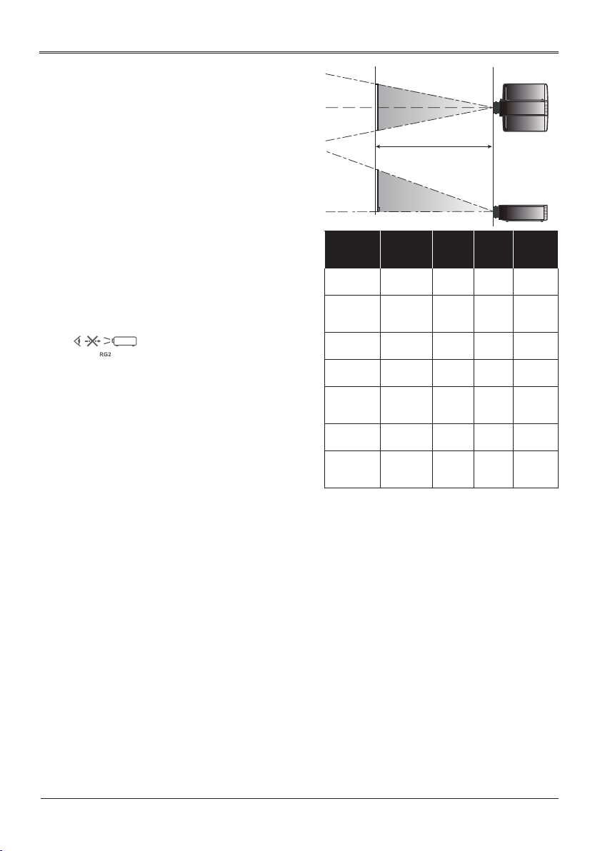
Adjusting Projection Image Size
Screen
Screen (W)
Side View
Projection Distance (D)
Diagonal
Height
Screen
Projection Distance (D)
0.1W
[A]
W
0.1W
[A]
H
Screen (H)
Width
Offset (Hd)
* Only with AH-AC21020/AH-AC24020/AH-
AC23020/AH-AC23030 lens
0.1W
[A]
W
0.1W
[A]
H
[A] differs when different lens is installed.
Lens [A]
AH-AC21020 0.6H
AH-AC22060 0.5H
AH-AC22070 0.6H
AH-AC24020 0.6H
AH-AC23020 0.6H
AH-AC23030 0.6H
AH-AC25020 N/A
37
Page 38

Basic Operations
Optional Lenses and projection size
Lens# AH-
AC21020
Throw Distance
@100”
Throw Ratio
Wide 3.47m 1.63m 2.45m 5.10m 7.60m 11.89m
Tele 5.20m 2.04m 3.67m 7.76m 12.15m 19.02m
Wide 1.61 0.76 1.14 2.37 3.53 5.52
Tele 2.42
Zoom Ratio
Zoom & Focus
adjustment
F / #
f / mm
Wide 1.60 1.84 1.82 1.80 1.80 1.84
Tile
Wide 24.1 11.3 17.2 35.2 51.3 1.84
Tile 35.8 14.1 25.5 53.5 82.5 126.00
Left/
Offset / %
Right
Up
0 - 60%
TOL 3.75%
Projection Image size
Optional Lens: AH-AC21020 / R3
Diagonal
length
(inch) size
of 16:10
Screen
60 1.29 0.81 50.88 31.80 2.08 3.12 6.83 10.24 -0.40 0.08 -1.32 0.26
70 1.51 0.94 59.36 37.10 2.43 3.64 7.97 11.95 -0.47 0.09 -1.55 0.31
80 1.72 1.08 67.84 42.40 2.78 4.16 9.11 13.66 -0.54 0.11 -1.77 0.35
90 1.94 1.21 76.32 47.70 3.12 4.68 10.24 15.37 -0.61 0.12 -1.99 0.40
100 2.15 1.35 84.80 53.00 3.47 5.20 11.38 17.07 -0.67 0.13 -2.21 0.44
120 2.58 1.62 101.76 63.60 4.16 6.24 13.66 20.49 -0.81 0.16 -2.65 0.53
150 3.23 2.02 127.20 79.50 5.20 7.81 17.07 25.61 -1.01 0.20 -3.31 0.66
180 3.88 2.42 152.64 95.40 6.24 9.37 20.49 30.73 -1.21 0.24 -3.97 0.79
200 4.31 2.69 169.60 106.00 6.94 10.41 22.77 34.15 -1.35 0.27 -4.42 0.88
250 5.38 3.37 212.00 132.50 8.67 13.01 28.46 42.68 -1.68 0.34 -5.52 1.10
300 6.46 4.04 254.40 159.00 10.41 15.61 34.15 51.22 -2.02 0.40 -6.62 1.32
Screen Size W x H Projection Distance (D) Offset (Hd)
(m) (inch) (m) (feet) (m) (feet)
Width Height Width Height Wide Tele Wide Tele Min. Max. Min. Max.
1.50
2.00
AHAC22060
0.95
1.25
2.32 2.32
0 - 50%
TOL 3.75%
AHAC22070
AHAC24020
1.71 3.60
1.50 1.52
AHAC23020
5.65 8.83
1.60 1.60
AHAC23030
Motorized Fixed
2.32 2.20
2.34
0 - ±10%
TOL 2.34%
0 - 60%
TOL 3.75%
0 - 60%
TOL 3.75%
0 - 60%
TOL 3.75%
0 - 60%
TOL 3.75%
60” - 300” 70” - 300”
AHAC25020
0.82m
0.38
Fix
2.00
5.64
Fixed
TOL 2.34%
83.2%
TOL 3.75%
38
Page 39

Basic Operations
Optional Lens: AH-AC22060 / R1
Diagonal
length
(inch) size
of 16:10
Screen
60 1.29 0.81 50.88 31.80 0.98 1.22 3.21 4.02 -0.40 0.00 -1.32 0.00
70 1.51 0.94 59.36 37.10 1.14 1.43 3.75 4.69 -0.47 0.00 -1.55 0.00
80 1.72 1.08 67.84 42.40 1.31 1.63 4.29 5.36 -0.54 0.00 -1.77 0.00
90 1.94 1.21 76.32 47.70 1.47 1.84 4.82 6.03 -0.61 0.00 -1.99 0.00
100 2.15 1.35 84.80 53.00 1.63 2.04 5.36 6.70 -0.67 0.00 -2.21 0.00
120 2.58 1.62 101.76 63.60 1.96 2.45 6.43 8.03 -0.81 0.00 -2.65 0.00
150 3.23 2.02 127.20 79.50 2.45 3.06 8.03 10.04 -1.01 0.00 -3.31 0.00
180 3.88 2.42 152.64 95.40 2.94 3.67 9.64 12.05 -1.21 0.00 -3.97 0.00
200 4.31 2.69 169.60 106.00 3.27 4.08 10.71 13.39 -1.35 0.00 -4.42 0.00
250 5.38 3.37 212.00 132.50 4.08 5.10 13.39 16.74 -1.68 0.00 -5.52 0.00
300 6.46 4.04 254.40 159.00 4.90 6.12 16.07 20.09 -2.02 0.00 -6.62 0.00
Optional Lens: AH-AC22070 / R2
Diagonal
length
(inch) size
of 16:10
Screen
60 1.29 0.81 50.88 31.80 1.47 2.20 4.82 7.23 -0.40 0.08 -1.32 0.26
70 1.51 0.94 59.36 37.10 1.71 2.57 5.62 8.44 -0.47 0.09 -1.55 0.31
80 1.72 1.08 67.84 42.40 1.96 2.94 6.43 9.64 -0.54 0.11 -1.77 0.35
90 1.94 1.21 76.32 47.70 2.20 3.31 7.23 10.85 -0.61 0.12 -1.99 0.40
100 2.15 1.35 84.80 53.00 2.45 3.67 8.03 12.05 -0.67 0.13 -2.21 0.44
120 2.58 1.62 101.76 63.60 2.94 4.41 9.64 14.46 -0.81 0.16 -2.65 0.53
150 3.23 2.02 127.20 79.50 3.67 5.51 12.05 18.08 -1.01 0.20 -3.31 0.66
180 3.88 2.42 152.64 95.40 4.41 6.61 14.46 21.69 -1.21 0.24 -3.97 0.79
200 4.31 2.69 169.60 106.00 4.90 7.35 16.07 24.10 -1.35 0.27 -4.42 0.88
250 5.38 3.37 212.00 132.50 6.12 9.18 20.09 30.13 -1.68 0.34 -5.52 1.10
300 6.46 4.04 254.40 159.00 7.35 11.02 24.10 36.16 -2.02 0.40 -6.62 1.32
Screen Size W x H Projection Distance (D) Offset (Hd)
(m) (inch) (m) (feet) (m) (feet)
Width Height Width Height Wide Tele Wide Tele Min. Max. Min. Max.
Screen Size W x H Projection Distance (D) Offset (Hd)
(m) (inch) (m) (feet) (m) (feet)
Width Height Width Height Wide Tele Wide Tele Min. Max. Min. Max.
39
Page 40

Basic Operations
Optional Lens: AH-AC24020 / R4
Diagonal
length
(inch) size
of 16:10
Screen
60 1.29 0.81 50.88 31.80 3.06 4.65 10.04 15.27 -0.40 0.08 -1.32 0.26
70 1.51 0.94 59.36 37.10 3.57 5.43 11.72 17.81 -0.47 0.09 -1.55 0.31
80 1.72 1.08 67.84 42.40 4.08 6.20 13.39 20.35 -0.54 0.11 -1.77 0.35
90 1.94 1.21 76.32 47.70 4.59 6.98 15.07 22.90 -0.61 0.12 -1.99 0.40
100 2.15 1.35 84.80 53.00 5.10 7.76 16.74 25.44 -0.67 0.13 -2.21 0.44
120 2.58 1.62 101.76 63.60 6.12 9.31 20.09 30.53 -0.81 0.16 -2.65 0.53
150 3.23 2.02 127.20 79.50 7.65 11.63 25.11 38.16 -1.01 0.20 -3.31 0.66
180 3.88 2.42 152.64 95.40 9.18 13.96 30.13 45.80 -1.21 0.24 -3.97 0.79
200 4.31 2.69 169.60 106.00 10.20 15.51 33.48 50.89 -1.35 0.27 -4.42 0.88
250 5.38 3.37 212.00 132.50 12.76 19.39 41.85 63.61 -1.68 0.34 -5.52 1.10
300 6.46 4.04 254.40 159.00 15.31 23.27 50.22 76.33 -2.02 0.40 -6.62 1.32
Optional Lens: AH-AC23020 / R5
Diagonal
length
(inch) size
of 16:10
Screen
60 1.29 0.81 50.88 31.80 4.56 7.30 14.96 23.94 -0.40 0.08 -1.32 0.26
70 1.51 0.94 59.36 37.10 5.32 8.51 17.46 27.93 -0.47 0.09 -1.55 0.31
80 1.72 1.08 67.84 42.40 6.08 9.73 19.95 31.92 -0.54 0.11 -1.77 0.35
90 1.94 1.21 76.32 47.70 6.84 10.95 22.45 35.92 -0.61 0.12 -1.99 0.40
100 2.15 1.35 84.80 53.00 7.60 12.16 24.94 39.91 -0.67 0.13 -2.21 0.44
120 2.58 1.62 101.76 63.60 9.12 14.60 29.93 47.89 -0.81 0.16 -2.65 0.53
150 3.23 2.02 127.20 79.50 11.40 18.24 37.41 59.86 -1.01 0.20 -3.31 0.66
180 3.88 2.42 152.64 95.40 13.68 21.89 44.89 71.83 -1.21 0.24 -3.97 0.79
200 4.31 2.69 169.60 106.00 15.20 24.33 49.88 79.81 -1.35 0.27 -4.42 0.88
250 5.38 3.37 212.00 132.50 19.01 30.41 62.35 99.76 -1.68 0.34 -5.52 1.10
300 6.46 4.04 254.40 159.00 22.81 36.49 74.82 119.72 -2.02 0.40 -6.62 1.32
Screen Size W x H Projection Distance (D) Offset (Hd)
(m) (inch) (m) (feet) (m) (feet)
Width Height Width Height Wide Tele Wide Tele Min. Max. Min. Max.
Screen Size W x H Projection Distance (D) Offset (Hd)
(m) (inch) (m) (feet) (m) (feet)
Width Height Width Height Wide Tele Wide Tele Min. Max. Min. Max.
40
Page 41

Basic Operations
Optional Lens: AH-AC23030 / R6
Diagonal
length
(inch) size
of 16:10
Screen
60 1.29 0.81 50.88 31.80 7.13 11.41 23.40 37.44 -0.40 0.08 -1.32 0.26
70 1.51 0.94 59.36 37.10 8.32 13.31 27.30 43.68 -0.47 0.09 -1.55 0.31
80 1.72 1.08 67.84 42.40 9.51 15.22 31.20 49.92 -0.54 0.11 -1.77 0.35
90 1.94 1.21 76.32 47.70 10.70 17.12 35.10 56.16 -0.61 0.12 -1.99 0.40
100 2.15 1.35 84.80 53.00 11.89 19.02 39.00 62.40 -0.67 0.13 -2.21 0.44
120 2.58 1.62 101.76 63.60 14.27 22.82 46.80 74.88 -0.81 0.16 -2.65 0.53
150 3.23 2.02 127.20 79.50 17.83 28.53 58.50 93.60 -1.01 0.20 -3.31 0.66
180 3.88 2.42 152.64 95.40 21.40 34.24 70.20 112.33 -1.21 0.24 -3.97 0.79
200 4.31 2.69 169.60 106.00 23.78 38.04 78.00 124.81 -1.35 0.27 -4.42 0.88
250 5.38 3.37 212.00 132.50 29.72 47.55 97.50 156.01 -1.68 0.34 -5.52 1.10
300 6.46 4.04 254.40 159.00 35.66 57.06 117.01 187.21 -2.02 0.40 -6.62 1.32
Optional Lens: AH-AC25020 / R0
Diagonal
length
(inch) size
of 16:10
Screen
70 1.51 0.94 59.36 37.10 0.59 0.59 1.94 1.94 0.24 0.24 0.77 0.77
80 1.72 1.08 67.84 42.40 0.67 0.67 2.19 2.19 0.28 0.28 0.92 0.92
90 1.94 1.21 76.32 47.70 0.74 0.74 2.43 2.43 0.32 0.32 1.07 1.07
100 2.15 1.35 84.80 53.00 0.82 0.82 2.68 2.68 0.37 0.37 1.21 1.21
120 2.58 1.62 101.76 63.60 0.97 0.97 3.18 3.18 0.46 0.46 1.51 1.51
150 3.23 2.02 127.20 79.50 1.20 1.20 3.92 3.92 0.59 0.59 1.95 1.95
180 3.88 2.42 152.64 95.40 1.42 1.42 4.67 4.67 0.73 0.73 2.39 2.39
200 4.31 2.69 169.60 106.00 1.57 1.57 5.16 5.16 0.82 0.82 2.68 2.68
250 5.38 3.37 212.00 132.50 1.95 1.95 6.41 6.41 1.04 1.04 3.41 3.41
300 6.46 4.04 254.40 159.00 2.33 2.33 7.65 7.65 1.26 1.26 4.15 4.15
Screen Size W x H Projection Distance (D) Offset (Hd)
(m) (inch) (m) (feet) (m) (feet)
Width Height Width Height Wide Tele Wide Tele Min. Max. Min. Max.
Screen Size W x H Projection Distance (D) Offset (Hd)
(m) (inch) (m) (feet) (m) (feet)
Width Height Width Height Wide Tele Wide Tele Min. Max. Min. Max.
41
Page 42

User Settings
t
e
N
o
• If no button
operation is made
for approximately
10 seconds, the
OSD will be closed
automatically.
User Settings
Using the On Screen Display (OSD)
The Projector has a multilingual On Screen Display that allows you to
make image adjustments and change a variety of settings.
How to Operate
1. To open the OSD, press “Menu” on the Control Panel or Remote
Control.
2. When OSD is displayed, use
the main menu. While making a selection on a particular page,
press “Enter” key to enter sub menu.
3. Use
keys to select the desired item in the sub menu and
press “Enter” key to view further settings. Adjust the settings by
using
key or
key.
4. Select the next item to be adjusted in the sub menu and adjust
as described above.
5. Press “Exit”, and the screen will return to the previous menu.
6. Press “Menu” or key to return to the main menu.
7. To exit, press “Menu” again. The OSD menu will close and the
projector will automatically save the new settings
keys to select any item in
.
Sub Menu
Image Adjustment
Enter
Standard
Setting
Standard(2.2)
White
Exit
Main Menu
Picture Mode
Brightness
Contrast
Saturation
Tint
Sharpness
Gamma
Color Temperature
HSG
Wall Color Mode
Select
42
Page 43

Image Adjustment
Picture Mode
Brightness
Contrast
Saturation
Tint
Sharpness
Gamma
Color Temperature
HSG
Wall Color Mode
Select Enter Exit
User Settings
Standard
Standard(2.2)
White
Image Adjustment
Picture Mode
There are factory presets optimized for various types of images.
The available options:
Bright: Mode for emphasizing brightness.
`
Standard: Mode for optimizing the balance between brightness
`
and color reproduction.
Vivid: Mode for emphasizing color.
`
sRGB: Mode for good color reproduction.
`
DICOM SIM.: Mode for viewing DICOM format les in simulation
`
mode, and not for the purpose of diagnosis.
User: Mode for recalling the settings customized based on the
`
current available picture modes.
Brightness
Adjust the brightness of the image.
Press the key to darken image.
`
Press the key to lighten the image.
`
Contrast
The contrast controls the degree of difference between the lightest
and darkest parts of the picture. Adjusting the contrast changes the
amount of black and white in the image.
Press the key to decrease the contrast.
`
Press the key to increase the contrast.
`
43
Page 44

User Settings
Saturation
Adjust the color saturation of the image.
Press the key to decrease the amount of color in the image.
`
Press the key to increase the amount of color in the image.
`
Tint
Adjust the color balance of the image.
Press the key to adjust the image color greenish.
`
Press the key to adjust the image color reddish.
`
Sharpness
Adjust the sharpness of the image.
Press the key to decrease the sharpness.
`
Press the key to increase the sharpness.
`
Gamma
Use this function to optimize the image output.
The available options: 1.8 / 2.0 / Standard(2.2) / 2.4 / DICOM SIM.
44
Color Temperature
Use this function to select the preset color temperature. The
available options: 5500/6500/7500/Native.
HSG
Use this function to enhance color and reproduce vivid colors.
On: Enable HSG.
`
Off: Disable HSG.
`
HSG Settings
`
Page 45

User Settings
–Color: Use
When selecting Red/Green/Blue/Cyan/Magenta/Yellow, the
following options are available.
a. Hue: Use
b. Saturation: Use
selected color.
c. Gain: Use
selected color.
When selecting White, the following options are available.
a. Red/Green/Blue: Use
color.
–Reset: Use this function to return the adjustments and settings
made above to the factory default values.
Wall Color Mode
`
Use this function to obtain an optimized screen image
according to the wall color. The available options: White/
Light Yellow/Light Blue/Pink/Dark Green.
key to select a color that you wish to enhance.
key to change the hue of the selected color.
key to change the saturation of the
key to change the contrast level of the
key to change the level of each
45
Page 46

Display Settings
t
e
Aspect
Phase
Frequency
H. Position
V. Position
Keystone
Lens
Advanced
User Settings
Auto
Select Enter
N
o
• "Phase",
"Frequency", "H.
Position" and "V.
Position" functions
are only supported
under Computer
Signal (VGA)
source.
Exit
Display Settings
Aspect
Use this function to choose your desired aspect ratio.
Auto: Automatically selects the appropriate display format.
`
When input is 4:3, the image is displayed as 4:3. When input is
16:9, the image is displayed as 16:9.
4:3/16:9/16:10/1.88:1/2.35:1: Display 4:3 / 16:9 / 16:10 / 1.88:1 /
`
2.35:1 aspect ratio.
Phase
Eliminate icker from the image displayed. Use the or key
to adjust the value.
Frequency
Adjust the number of total dots in one horizontal period. Use the
or key to adjust number to match your PC image.
H. Position (Horizontal Position)
Shift the projected image position horizontally.
Press the key to move the image left.
`
Press the key to move the image right.
`
V. Position (Vertical Position)
Shift the projected image position vertically.
Press the key to move the image down.
`
Press the key to move the image up.
`
46
Page 47

User Settings
Keystone
Adjust image distortion caused by tilting the projector.
V Keystone: Adjust the vertical keystone.
`
H Keystone: Adjust the horizontal keystone.
`
Four Corners: Compensate for image distortion by adjusting
`
one corner at a time.
a. Use the or key to select the item to select which corner
to adjust and press the “Enter” key to enter its submenu.
b. Use the , , , or key to adjust the setting.
Reset: Return the keystone settings to the factory default
`
values.
Lens
Lens Settings
`
–Lens Lock: Selecting Yes will lock all the functions provide in
this menu and the Lens Centering menu. You will not be able
to change lens related settings.
–Lens Shift: Press or to select Normal Speed or
Fine Tune to determine how fast you want the lens to move.
After selection, press Enter to enable the lens shift function,
and use , , , or to adjust the projection position.
–Focus: Use , , , or to adjust the image clarity.
–Zoom: Use , , , or to adjust the image size.
–Load Settings: Recalls the settings that you previously saved.
–Save Settings: After making lens shift, zoom and focus
adjustments, you can choose a set of setting to memorize
current lens settings.
–Clear Settings: Clear the selected lens setting.
Lens Centering
`
Returns the lens to the centered position.
47
Page 48

User Settings
Advanced
`
RGB Input Range
Adjust the color range of the HDMI image data.
–Auto: Automatically detect RGB range.
–Limited Range: Process the input image as standard range
data.
–Full Range: Select this mode when a computer signal or full
range signal from AV equipment is input.
`
Overscan
Use this function to conceal the poor picture quality in the four
edges.
`
Start-up Screen
Use this function to select an image to be displayed during
the projector start up procedure. The available options:
Logo/User/Off.
`
Background on No Signal
Use this function to select a background image to be
displayed when no signal is detected. The available options:
Logo (User)/Blue/Black.
`
Screen Capture
Use this function to customize the start-up screen.
a. Project the image you want to capture.
b. Select “Screen Capture“ and press “Enter”.
c. A dialog box appears to conrm the action. Choose “Yes” to
use the current image as your customized start-up screen.
(Choose “No” to cancel the screen capture and exist the
Onscreen Display).
d. A message appears stating that the screen capture is in
progress.
e. When the screen capture is nished,
“Screen capture succeeded!“ message will pop up. If the
screen capture failed, a “Screen Capture FAILED!“ message
will pop up. Your image size may exceed the maximum
capturing capacity of 8 MB. Please change another image
and try again.
f. To use this image as the startup screen, select “User“ in
“Start-up Screen“.
48
Page 49

User Settings
g. To use this image as signal searching screen, select
“User“ in “Start-up Screen“ and “Logo (User)“ in
“Background on No Signal“.
`
Test Pattern
Use this function to display different test patterns to help
you adjust the size, focus and colors and check that the
projected image is free from distortion. The available options:
Off/Grid/White/Color Bar/Black/Red/Green/Blue/Cyan/
Yellow/Magenta.
`
Closed Caption
Use this function to select a preferred closed captioning mode.
Caption is an on-screen display of the dialogue, narration,
and sound effects of TV programs and videos that are closed
captioned (usually marked as “CC” in TV listings). The available
options: Off/CC-1/CC-2/CC-3/CC-4. CC-1 displays captions in
the primary language in your area.
49
Page 50

Default Settings
Language
Menu Display Time
Menu Position
Projector Installation
Auto Source
Input Source
Power Settings
Standby Settings
Network
Security
Reset
Select
User Settings
10 sec
Top-Left
Front Table
On
Enter Exit
Default Settings
Language
Choose the Language for the On Screen Display menus.
English, German, French, Italian, Spanish, Traditional Chinese,
Simplied Chinese, Dutch, Russia, Korean
Menu Display Time
Select the length of time the On Screen Display will remain active
after your last key press.
50
Menu Position
Select the On Screen Display menu position.
Projector Installation
Use this function to select the projector mode, depending upon
how the projector is mounted.
Front Table: This is the default selection. The image is projected
`
straight on the screen.
Rear Table: When selected, the image will appear reversed.
`
Rear Ceiling: When selected, the image will appear reversed in
`
upside down position.
Front Ceiling: When selected, the image will turn upside down.
`
Auto Source
When this function is turned “On”, the projector will search for
other signals if the current input signal is lost. When this function is
turned “Off”, it will only search a specied connection port.
Input Source
Use this option to enable/disable input sources. Press “Enter” to
Page 51

N
e
t
o
• Default value of
“Auto Power Off (Min)”
is 20 min.
User Settings
enter the sub menu and select which sources you require. Press
“Enter” to nalize the selection. The projector will only search for
inputs that are enabled.
Power Settings
Direct Power On: Choose “On“ to activate this function.
`
The projector will automatically power on when AC power is
supplied, without pressing the
Start on Input Detection: Choose “On“ to activate this function.
`
The projector will automatically power on when a VGA signal is
detected, without pressing the
Power Off Notice: When “On” is selected, a power off message
`
will be displayed after pressing the
selected, the projector turns off after pressing the
one time.
Date & Time: Set the date and time for this projector.
`
Auto Power Off (Min): Sets the countdown timer interval. The
`
countdown timer will start, when there is no signal being sent to
the projector. The projector will automatically power off when the
countdown has nished (in minutes). When countdown timer is
selected to “0”, auto power off is disabled.
Customer Power Off (Hours): Schedule automatic shutdown of
`
the projector.
button.
button.
button. When “Off” is
button
Standby Settings
Monitor Out
`
Enable/Disable the Monitor output function.
–On: Enable the Monitor Out function at projector standby
status.
–Off: Disable the Monitor Out function at projector standby
status.
Network
`
Enable/Disable the network function.
–On: Enable the network function at projector standby status.
–Off: Disable the network function at projector standby status.
DC 5V Out
`
Use this function to enable DC 5V power output through the
USB-A terminal.
HDBaseT IR Carrier
`
Use this function to enable HDBaseT IR Carrier.
51
Page 52

N
e
t
o
• The default
securitycode is
“12345678”.
User Settings
Network
Congure the network settings.
Status: Display the network connection status.
`
DHCP: Select On to allow the projector to obtain an IP address
`
automatically from your network. Select “Off” to manually assign
IP, Subnet Mask and Gateway conguration.
IP Address: Set an IP address or display IP address provided
`
from DHCP server when DHCP is set to “On”.
Subnet Mask: Set subnet mask number or display subnet mask
`
number provided from DHCP server when DHCP is set to “On”.
Apply: Select “Yes” to apply the changes made in network
`
conguration settings.
MAC Address: Display MAC address.
`
Security
Congure the security settings.
Password Protection: Select “On” to use the security verication
`
when the turning on the projector. Select “Off” to be able to
switch on the projector without password verication.
Change Password: Set the password.
`
Lock to User Startup Screen: Use this function to lock
`
the Startup Screen and it cannot be changed by the
“Start-up Screen“ or “Screen Capture“ function.
Reset
Return the adjustments and settings to the factory default values.
Choose “Yes” to return the display parameters on all menus except
Language to the factory default settings.
52
Page 53

Options
e
e
Laser Mode
High Altitude Mode
Status Display
Control
3D
Information
User Settings
Normal
Off
On
Select
N
t
o
• When ambient
temperature is over
40°C in operating,
the projector will
switch to “ECO”
automatically.
N
t
o
• Compatible 3D
source, 3D content
and Optical 3D
glasses are required
for 3D viewing.
• “3D Sync Invert” is
only available when
3D is enabled.
• This setting may
need to change
when re-start running
3D movie.
• 3D function is turned
on automatically
when Blu-ray 3D
source is input.
Enter Exit
Options
Laser Mode
Set the brightness mode. Choose “Normal” to increase the
brightness or choose “ECO” to dim the projector light source which
will lower power consumption and extend the light source life.
High Altitude Mode
When “On” is selected, the fans will spin faster. Set High Altitude
mode to “On” when the projector is used over 1500m elevation.
Status Display
When “On” is selected, the status will be displayed.
Control
HDMI CEC: Use this function for synchronized power ON/OFF
`
operation between the projector and a CEC-compatible device
connected to the HDMI/MHL port of the projector.
Projector ID: Set the remote control ID for this projector. When
`
multiple adjacent projectors are in operation at the same time,
switching the remote control codes can prevent interference
from other remote controls. After the Projector ID is set, switch
to the same ID for the remote control to control this projector.
Trigger Out: Set the port to provide trigger out function. The
`
available options: Off/DC Out 1/DC Out 2/1 & 2.
3D
3D Sync: Use this option to select the appropriate 3D function.
`
–DLP-Link: Choose “DLP-Link” to use DLP Link 3D Glasses.
–External: Choose “External” to use VESA 3D emitter and 3D
Glasses.
53
Page 54

User Settings
3D Sync Output: Use this option to select the appropriate 3D
`
sync output method.
–Normal: Choose “Normal“ to output 3D sync to other
projector(s).
–Pass Through: Choose “Pass Through“ to receive 3D sync and/
or pass 3D sync to another projector.
3D Format: Use this option to select the appropriate 3D format
`
content.
–Auto: Use this function for the projector to automatically
select the 3D format depending on the 3D content.
–Side by Side: Use this mode for “Side by Side” format 3D
content.
–Top and Bottom: Use this mode for “Top and Bottom” format
3D content.
–Frame Sequential: Use this mode for “Frame Sequential”
format 3D content.
3D Sync Invert: Use this option to enable/disable the 3D sync
`
invert function.
–Off: Choose “Off” for default frame contents.
–On: Choose “On” to invert left and right frame contents
.
54
Information
Display the projector information.
Source: Display the input source that is currently connected to.
`
Resolution: Display the resolution setting of the current input
`
source.
Picture Mode: Display current Picture Mode.
`
Laser Mode: Display current Laser Mode.
`
Total Time: Display the light source hours.
`
Inlet Temp: Display the temperature of the intake vent.
`
FW Version: Display the rmware version.
`
Page 55

User Settings
Menu Tree
Main menu Sub-menu Setting Default value Remarks
Picture Mode
Brightness 0-100
Contrast 0-100 50
Saturation 0-100 50
Tint 0-100 50
Sharpness 0-15 8
Image Adjustment
Display Setting
Gamma
Color Temperature
HSG HSG ON
Wall Color Mode
Aspect
Phase 0-31 16
Frequency -10-10 0
H. Position -10-10 0
V. Position -10-10 0
Keystone
Lens Lens Setting
Bright
Standard
Vivid
sRGB
DICOM SIM.
User
1.8
2
Standard (2.2)
2.4
DICOM SIM.
5500
6500
7500
Native
HSG setting
White
Light Yellow
Light Blue
Pink
Dark Green
Auto
4 : 3
16 : 9
16 : 10
1.88 : 1
2.35 : 1
V Keystone 0
H Keystone 0
Four Corners
Reset
Lens Centering
Standard
50
Standard(2.2)
6500
White
Auto
55
Page 56

Display Setting Advanced
Language
Menu Display Time
Defaults Setting
Menu Position
Projector Installation
Auto Source
Input Source
User Settings
RGB Input Range Auto
Overscan Off
Start-up Screen Logo
Background On No
Signal
Screen Capture
Test Pattern
Closed Caption Off
English
German
French
Italian
Spanish
Traditional Chinese
Simplied Chinese
Russian
Korean
Dutch
5 sec
10 sec
20 sec
30 sec
always
Center
Top-Left
Top-Right
Bottom-Right
Bottom-Left
Front Table
Rear Table
Rear Ceiling
Front Ceiling
On
Off
Computer1
Computer2
HDMI 1 / MHL
DVI-D
Video
S-Video
HDBaseT
3G-SDI
Logo(User)
Off
English
10 sec
Top-Left
Front Table
On
56
Page 57

Defaults Setting
Options
Power Settings
Standby Setting
Network
Security
Reset
Laser Mode
High Altitude Mode
Status Display
Control
3D
Information
User Settings
Direct Power On Off
Start on Input Detection Off
Power Off Notice ON
Date & Time
Auto Power Off (Min.) 20
Customize Power Off
(Hours)
Monitor Out Off
Network Off
DC 5V Out Off
HDBaseT IR Carrier
Status
DHCP
IP Address
Subnet Mask
Apply
MAC Address
Password Protection Off
Change Password
Lock to User Startup
Screen
Normal
Eco
On
Off
On
Off
HDMI CEC
Projector ID 0
Trigger Out
3D Sync
3D Sync Output
3D Format
3D Sync Invert
Source
Resolution
Picture Mode
Laser Mode
Total Time
Inlet Temp
FW Version
Off
Off
Normal
Off
On
57
Page 58

LAN Control
LAN Control
Wired LAN Terminal functionalities
Remote control and monitoring of a projector from a PC (or Laptop)
via wired LAN is also possible.
Compatibility with Crestron control boxes enables not only collective
projector management on a network
but also management from a control panel on a PC (or Laptop)
browser screen.
• Crestron is a registered trademark of Crestron Electronics, Inc. of
the United States.
Supported External Devices
This projector is supported by the specied commands of the
Crestron Electronics controller and related
Software. The projector supports AMX and PJ-Link as well.
RS232 LAN control (RJ45)
Model Number
EK-830U.831U
(D-sub 9pin)
Web
browser
TELNET
PJ Link
Ver. 1.0
(4352) (41794) (9131)
Crestron AMX
Port number
58
http://www.crestron.com/
http://www.amx.com/
https://pjlink.jbmia.or.jp/english/index.html
Page 59

LAN Control
e
Controlling this Device with Web
Browser
You can control this device from a PC by using a web browser.
Connecting to the Device
Conrmation of the IP address of the device
1.
Go to the “Default Settings” > “Network” menu of this device,
and verify the IP address.
Connection
2.
Enter the IP address that was veried by opening the web
browser.
For example, enter http://192.168.0.100/ if the IP address is
displayed.
Crestron
Once connected, you can control the projectors via Crestron
program.
N
t
o
• When projector is in
standby mode, only
the “Power” button
will work.
Power: Switch ON/OFF the power.
`
Source List: Correspondence between the input display and
`
input terminal of the device is as follows.
• Computer
• S-Video
• Video
Other buttons work in the same manner as those on the
`
projector control panel or the remote control do.
• HDMI1/MHL
• HDMI2
59
Page 60

N
e
e
t
o
• After setting the
user password,
you will be able to
access Crestron’s
page by entering the
password.
• After enabling the
Admin password,
you will be able to
access the page of
Crestron tool only
upon entering the
Admin password.
N
t
o
• Crestron offers the
following two types of les.
1. RoomViewExpress
_6_3_3_7.exe
2. Xpanel.exe
LAN Control
Crestron Tools
You can manage the projector, congure the LAN control setting,
and secure remote network operation on this page.
Crestron Info
This page displays information about the rmware version of the
projector and status of the light source.
60
Page 61

Troubleshooting
e
Regular maintenance
N
t
o
• Unplug the AC
power cord before any cleaning operation.
Clean your projector when it is contaminated by foreign matter or its
display effects are getting worse.
Clean the lens
Wipe the lens with clean cloth dampened with non-abrasive camera
lens cleaner or clean it with lens cleaning paper or air blower.
Do not over apply cleaner to the lens. Abrasive cleaner, solution, or
other rough chemical may scratch the lens.
Clean casing of your projector
Wipe the casing surface with clean and soft cloth. Gently wipe the casing with clean and soft cloth dampened with small amount of neutral
detergent to remove heavy dirt. Do not over apply cleaner to the casing. Abrasive cleaner, solution, or other rough chemical may scratch the
casing surface.
Place your projector in proper container after use to protect it from dirt
and dust and being scratched.
61
Page 62

Troubleshooting
Troubleshooting
If you experience trouble with the projector, refer to the
following information. If the problem persists, please contact
your local dealer or service center.
Image Problem
No image appears on screen
Ensure all the cables and power connections are correctly
`
and securely connected as described in the “Connecting the
Projector” section.
Ensure the pins of terminals are not crooked or broken.
`
Make sure you have removed the lens cap (if any) and the
`
projector is switched on.
Partial, scrolling or incorrectly displayed image
Press “Auto Set” on the projector’s control panel, or adjust the
`
Display Settings > Phase / Frequency / H. Position / V. Position
menu.(refer P.51)
Adjust the computer display settings. Verify the resolution
`
setting is less than or equal to 1920 x 1200 resolution. (refer
P.51)
If you are using a Notebook:
`
1. First, follow the steps above to adjust resolution of the
computer.
2. Press the toggle output settings. For example: [Fn]+[F3]
PANASONIC, NEC => Fn+F3
HP, SHARP, TOSHIBA => Fn+F5
IBM, SONY => Fn+F7
DELL, EPSON => Fn+F8
FUJITSU => Fn+F10
APPLE =>F7
62
If you experience difculty changing resolutions or your monitor
`
freezes, restart all equipment including the projector.
The screen of the Notebook computer is not displaying
a presentation
If you are using a Notebook PC:
`
Some Notebook PCs may deactivate their own screens when
a second display device is in use. Each has a different way to
be reactivated. Refer to your computer’s documentation for
detailed information.
Page 63

Troubleshooting
Image is unstable or ickering
Adjust the “Phase” or “Clock” to correct it.
`
Refer to the “H. Position (Horizontal Position)” or “V. Position
(Vertical Position)” section for more information.(refer P.51)
Check and recongure the display mode of your graphics card
`
to make it compatible with the product.
Image is out of focus
Adjust the Focus.
`
Make sure the projection screen is between the required
`
distance.
The image is stretched when displaying 16:9 DVD
Change the aspect ratio by pressing the “Aspect” button on the
`
remote control or select “Display Settings” > “Aspect” from the
OSD menu to show the image with proper aspect ratio.(refer
P.51)
Image is too small or too large
Press the “Zoom” button on the remote control or go to the
`
Display Settings > Lens > Lens Settings > Zoom menu to
magnify or reduce the image size. (refer P.51)
Move the projector closer to or further from the screen.
`
Press the “Aspect” button on the remote control or go to the
`
Display Settings > Aspect and try different settings.(refer P.51)
Image is reversed
Go to the Default Settings > Projector Installation menu to
`
adjust the image position.
Laser Diode Problem
No light from the projector
Ensure all the cables and power connections are correctly
`
and securely connected as described in the “Connecting the
Projector” section.
Ensure the pins of terminals are not crooked or broken.
`
The laser diode goes off
Ensure all the cables and power connections are correctly.
`
Check the LED indicator lighting message.(refer P.64-65)
`
63
Page 64

N
e
t
o
• Steady light =>
• No light =>
Troubleshooting
Indicator lighting message
Indicator
Status
Normal Operation
Standby
Powering up
Normal
(Power ON)
Cooling
Firmware
download
Warning
Timer
backup error
(Standby)
Laser fail
(1 bank)
Laser fail
(2 banks)
Laser fail
(3 banks)
Laser fail
(4 banks)
Laser fail
(5 banks)
Laser fail
(6 banks)
Laser fail
(7 banks)
Laser fail
(All banks)
Temperature
1 error
Temperature
2 error
Fan 1 error
Power Temp Status1 Status2 Status3
Blue Red Red Red Red Red
Flashing
(0.5 sec)
Flashing
(0.5 sec)
Flashing
(0.2 sec)
Flashing
(0.5 sec)
Flashing
(0.5 sec)
Flashing
(0.5 sec)
Flashing
(0.5 sec)
64
Page 65

Status
Fan 2 error
Fan 3 error
Troubleshooting
Indicator
Power Temp Status1 Status2 Status3
Blue Red Red Red Red Red
Fan 4 error
Fan 5 error
Fan 6 error
Fan 7 error
Fan 8 error
Fan 9 error
Fan 10 error
Fan 11 error
Fan 12 error
Fan 13 error
Fan 14 error
Fans error
Color wheel
failure
Phosphor
wheel 1 error
Phosphor
wheel 2 error
Liquid pump
1 error
Liquid pump
2 error
Liquid pump
1 & 2 error
Flashing
(0.5 sec)
Flashing
(0.2 sec)
Flashing
(0.5 sec)
Flashing
(0.5 sec)
Flashing
(0.5 sec)
Flashing
(0.5 sec)
65
Page 66

Troubleshooting
Remote Control Problem
The projector does not respond to the remote control
Check Remote control battery.
`
Problem: Message Reminders
Temperature Error - the projector is overheating inside. Check
`
the environmental condition.
Error
Projector Overheated.
Laser will automatically turn off soon.
Liquid cooler Error - the water is insufcient.
`
Notify
The water in liquid cooler is insufcient. Contact the service center
for replacement.
Service
If you are unable to solve the problem, you should have the
`
projector serviced.
Pack the projector in the original carton. Include a description of
`
the problem and a checklist of the steps you took when trying
to x the problem. The information may be useful to service
personnel. For servicing, return the projector to the place you
purchased it.
66
Page 67

Appendices
Appendices
List of Compatible Signals
A. VGA Analog
(1) VGA Analog - PC Signal
Modes Resolution V.Frequency (Hz)
60 31.47
72 37.86
VGA 640 x 480
SVGA
XGA 1024 x 768
SXGA
QuadVGA
SXGA+ 1400 x 1050 60 65.32
UXGA 1600 x 1200 60 75
PowerBook G4
800 x 600
1152 x 864
1280 x 1024
1280 x 960 60 60
1280 x 960 75 75
640 x 480 60 31.5
640 x 480 66.6 (67) 35
800 x 600 60 37.88
1024 x 768 60 48.36
1024 x 768 75 60.241
1152 x 870 75 68.681
75 37.5
85 43.27
120 61.91
56 35.2
60 37.88
72 48.08
75 46.88
85 53.67
120 77.43
60 48.36
70 56.48
75 60.02
85 68.68
120 98.96
70 63.85
75 67.5
85 77.1
60 63.98
72 76.97
75 79.98
85 91.15
H.Frequency
(kHz)
67
Page 68

Appendices
A. VGA Analog
(1) VGA Analog - PC Signal
Modes Resolution V.Frequency (Hz)
1280 x 768 60 47.78
WXGA
HD 720 1280 x 720 60 45
WXGA
WSXGA+ 1680 x 1050 60 65.29
16:9 1366 x 768 60 47.71
HD 1080
WSVGA 1024 x 600 60 37.5
WUXGA 1920 x 1200-RB 59.95 74.04
B. HDMI
(1) HDMI - PC Signal
Modes Resolution V.Frequency (Hz)
VGA_60
VGA_72 72.809 37.861
VGA_75 75 37.5
VGA_85 85.008 43.269
VGA_120 119.518 61.91
SVGA_56
SVGA_60 60.317 37.879
SVGA_72 72.188 48.077
SVGA_75 75 46.875
SVGA_85 85.061 53.674
SVGA_120
XGA_60
XGA_70 70.069 56.476
XGA_75 75.029 60.023
XGA_120 119.804 98.958
1280 x 768 75 60.29
1280 x 768 85 68.63
1280 x 800 60 49.7
1280 x 800 - RB 120 101.6
1440 x 900 60 55.94
1920 x 1080-RB 60 66.6
1920 x 1080-EIA 60 67.5
59.94 31.469
640 x 480
56.25 35.156
800 x 600
119.854 77.425
60.004 48.363
1024 x 768
H.Frequency
(kHz)
H.Frequency
(kHz)
68
Page 69

Appendices
B. HDMI
(1) HDMI - PC Signal
Modes Resolution V.Frequency (Hz)
SXGA_75
SXGA_85
SXGA_60
SXGA_72 72 76.97
SXGA_75 75.025 79.976
SXGA_85 85.024 91.146
QuadVGA_75 1280 x 960 75 75
SXGA+_60 1400 x 1050 59.978 65.317
UXGA_60 1600 x 1200 60 75
Mac G4 640 x 480@60Hz 59.94 31.469
MAC13
Mac G4 800 x 600@60Hz 60.317 37.879
Mac G4
MAC19
MAC21 1152 x 870@75Hz 75.061 68.681
WXGA_60
WXGA_75 74.893 60.289
WXGA_85 84.837 68.633
1152 x 864
1280 x 1024
640 x 480@67Hz 66.667 35
1024 x 768@60Hz 60.004 48.363
1024 x 768@75Hz 75.02 60.241
1280 x 768
75 67.5
84.99 77.094
60.02 63.981
59.87 47.776
H.Frequency
(kHz)
69
Page 70

Appendices
B. HDMI
(1) HDMI - PC Signal
Modes Resolution V.Frequency (Hz)
WXGA_60 1280 x 720 60 45
WXGA_60
WXGA_120-RB 1280 x 800 119.909 101.563
WXGA+_60 1440 x 900 59.887 55.935
1680x1050_60 1680 x 1050 59.954 65.29
16:9 1366 x 768 59.79 47.712
1920 x 1080_RB 1920 x1080 60 66.587
1920 x 1080_EIA 1920 x1080 60 67.5
1920 x 1200-RB 1920 x 1200 59.95 74.038
(2) HDMI - Video Signal
480i
480p 720 x 480 60 31.47
576i
576p 720 x 576 50 31.25
720p 1280 x 720 60 45
720p 1280 x 720 50 37.5
1080i 1920 x 1080 60 33.75
1080i 1920 x 1080 50 28.13
1080p 1920 x 1080 60 67.5
1080p 1920 x 1080 50 56.26
1080p 1920 x 1080 24 27
1080p 1920 x 1080 23.98 26.97
1080p 1920 x 1080 24 27
1080p 1920 x 1080 23.98 26.97
1280 x 800 59.81 49.702
720 x 480
(1440 x 480)
720 x 576
(1440 x 576)
60 15.73
50 15.63
H.Frequency
(kHz)
70
C. MHL
(1) MHL - Video Signal
Modes Resolution V.Frequency (Hz)
480i
480p 720 x 480 60 31.47
576i
576p 720 x 576 50 31.25
720 x 480
(1440 x 480)
720 x 576
(1440 x 576)
60 15.73
50 15.63
H.Frequency
(kHz)
Page 71

Appendices
C. MHL
(1) MHL - Video Signal
Modes Resolution V.Frequency (Hz)
720p 1280 x 720 60 45
720p
1080i 1920 x 1080 60 33.75
1080i 1920 x 1080 50 28.13
1080p 1920 x 1080 24 27
1080p 1920 x 1080 23.98 26.97
1080p 1920 x 1080 30 33.75
D. YPbPr
Modes Resolution V.Frequency (Hz)
480i 720 x 480 59.94 15.73
480p 720 x 480 59.94 31.47
576i 720 x 576 50 15.63
576p 720 x 576 50 31.25
720p 1280 x 720 60 45
720p 1280 x 720 50 37.5
1080i 1920 x 1080 60 33.75
1080i 1920 x 1080 50 28.13
1080p 1920 x 1080 60 67.5
1080p 1920 x 1080 50 56.26
1080p 1920 x 1080 24 27
1080p 1920 x 1080 23.98 26.97
1280 x 720 50 37.5
H.Frequency
(kHz)
H.Frequency
(kHz)
E. Video, S-Video
Modes Resolution V.Frequency (Hz)
NTSC 15.73 60 3.58
PAL 15.63 50 4.43
SECAM 15.63 50 4.25 or 4.41
PAL-M 15.73 60 3.58
PAL-N 15.63 50 3.58
PAL-60 15.73 60 4.43
H.Frequency
(kHz)
71
Page 72

Appendices
E. Video, S-Video
Modes Resolution V.Frequency (Hz)
NTSC4.43 15.73 60 4.43
F. 3D Timming
Input timing
1280 X 720P @ 50Hz Top - and - Bottom
1280 X 720P @ 60Hz Top - and - Bottom
HDMI 3D
Input (with 3D
Info Frame
information)
Input
Resolutions
HDMI 3D
Input (without
3D Info Frame
information)
VGA (PC)
Composite NTSC HQFS
S-Video NTSC HQFS
1280 X 720P @ 50Hz Frame packing
1280 X 720P @ 60Hz Frame packing
1920 X 1080i @ 50 Hz Side- by-Side (Half)
1920 X 1080i @ 60 Hz Side- by-Side (Half)
1920 X 1080P @ 24
Hz
1920 X 1080P @ 24
Hz
1920 x 1080i @ 50Hz
1920 x1080i @ 60Hz
1280 x 720P @ 50Hz
1280 x 720P @ 60Hz
1920 x 1080i @ 50Hz
1920 x1080i @ 60Hz
1280 x 720P @ 50Hz
1280 x 720P @ 60Hz
480i HQFS
800x600 @ 60Hz
1024x768 @ 60Hz
800x600 @ 120Hz
1024x768 @ 120Hz
Top - and – Bottom
Frame packing
Side-by-
Side
(Half)
Top-and-
Bottom
SBS or TAB
Frame Sequential
H.Frequency
(kHz)
SBS mode
is on
TAB mode
is on
72
Page 73

Appendices
e
Congurations of Terminals
Terminal: Computer In (Mini D-sub 15 pin)
[Monitor Out]
54321
10 9876
15 14 13 12 11
1 Red (R/Cr) Input [R Output] 9 DDC 5V [NC*]
2 Green (G/Y) Input [G Output] 10 Ground (Ver. sync.)
3 Blue (B/Cb) Input [B Output] 11 NC*
4 NC* 12 DDC Data [NC*]
5 Ground (Horiz.sync.) 13 Horiz. sync. Input [Output] (Composite H/
6 Ground (Red)
7 Ground (Green) 14 Vert. sync. Input [Output]
8 Ground (Blue) 15 DDC CLK [NC*]
*Do not connect anything.
Terminal: PC Control (D-sub 9 pin) (male)
V sync. Input)
N
t
o
• Contact
your dealer
for control
cable and
commands.
9876
5 4321
1 NC* 6 NC*
2 RXD (Receiving Data) 7 NC*
3 TXD (Sending Data) 8 NC*
4 NC* 9 NC*
5 GND * Do not connect anything.
73
Page 74

N
e
e
t
e
t
o
• Contact
your dealer
for control
cable and
commands.
N
t
o
• Contact your
dealer for
control cable.
Appendices
Terminal: 3D Sync
1 +5VDC
2 GND
3 Stereo Sync
TTL Signal Parameter
high” state >= 2.4 V for left-eye image >=2.4v
low” state<=0.8 V for right-eye image; <=0.8v
Duty cycle 50%
Terminal: 12V Trigger Out
1 3
2
N
o
• Contact your
dealer for
control cable.
74
1 GND
2 12V
3 NC
Terminal: Wired Remote In/Out
IR Receivers
1 5V
2 IR signal (NEC Format)
3 Ground
Page 75

Appendices
Specications
Mechanical properties
Dimensions (W×H×D ) 548mmx554.2mmx189mm (without lens)
Net Weight 26.5 ± 0.5Kg (without lens)
Adjustable foot Max. Hight to 26.5mm
LCD resolution
LCD system 0.67" TFT
LCD resolution 1920X1200
Compatible signals
Color standard PAL, SECAM, NTSC, NTSC4.43, PAL-60, PAL-M and PAL-N
HDTV signal 480i, 480p, 576i, 576p, 720p, 1080p and 1080i
Scanning frequency Horizontal frequency: 15–100 KHz; Vertical frequency: 24–120 Hz
Optical elements
Image size (diagonal lines)
Projection distance
Lens (Standard Lens)
Contrast Ratio Innity with Dynamic Black mode
Aspect Ratio 16:10
Terminal
S-Video S-Video Mini Din 4pin x1
BNC / Component BNC x 5 (G or Y, B or Pb, R or Pr, H and V)
Video RCA x1
DVI-D 24pin DVI-D
Computer IN Mini D-sub 15 pin x1
Monitor OUT Mini D-sub 15 pin x1
HDMI (MHL) HDMI Type A x1
DC 5V OUT USB type A x1
12V Trigger Out 3.5mm Mini Jack Stereo x22
USB-B Mini USB type B x1
Wired remote control input terminal Mini Jack, 3.5mm x1
Wired remote control output terminal Mini Jack, 3.5mm x1
RS232 Input D-sub 9 pin x1
RS232 Output D-sub 9 pin x1
HDBaseT terminal RJ45 x1
3G-SDI Input BNC x1
3G-SDI Output BNC x1
LAN terminal RJ45 x1, 100 Base-TX (100Mbps)/10 Base-T (10Mbps)
3D sync Input 3 pin mini DIN receptacle
3D sync Output 3 pin mini DIN receptacle
Power
Power supply AC 100–240 V, 50/60 Hz
Operating Environment
Operating temperature 32˚F-104˚F (0˚C-40˚C)
Storage Temperature 14˚F-149˚F (-10˚C-60˚C)
High land 3000 m
Remote control
Battery AAA 1.5V ALKALINE TYPE x 2
Operating Range 23.0' (7m) / ±30° (horizontally) / ±20° (vertically)
Dimensions 46mm (W) x 175mm (H) x 21mm (D)
Net Weight 75g (without batteries)
Accessories
Safety Guide AC power cord (US Type x 1 / Euro Type x 1)
Quick Start Guide VGA cable
Remote control and batteries
• Designs and specications are subject to change without notice.
• This model may not be compatible with features and/or specications that may be added in the future.
60"-300"
Wide: 2.08m ~ 10.41m / Tele: 3.12m ~ 15.61m(with Standard Lens)
F = 1.6~2.0 / f =24.1~35.8mm; Zoom ratio: 1.5x
75
Page 76

Appendices
Cabinet Dimensions
Unit: mm
548
552.5
179
[B]
189
76
Holes for ceiling mount
Screw type: M6
Thread the screw into
the hole for 8mm (min.)
to 10mm (max.) thick.
175
275
[C]
[B] and [C] differ when different lens are installed.
Lens installed [B] [C]
AH-AC21020 594 216
AH-AC22060 610 232
AH-AC22070 611 233
AH-AC24020 632 253
AH-AC23020 632 253
AH-AC23030 632 253
AH-AC25020 815 436.2
250
Page 77

Appendices
Trademarks
• DLP is trademarks or registered trademark of Texas
Instruments.
• Microsoft, Windows, Windows Vista, Internet Explorer and
PowerPoint are either a registered trademark or trademark
of Microsoft Corporation in the United States and/or other
countries.
• HDMI, the HDMI Logo and High-Denition Multimedia
Interface are trademarks or registered trademarks of HDMI
Licensing LLC.
• MHL, Mobile High-Denition Link, and MHL Logo are
trademarks or registered trademarks of MHL, LLC.
• Kensington is a trademark or registered trademark of ACCO
Brands.
• Blu-ray is a trademark of Blu-ray Association.
• HDBaseT™ and the HDBaseT Alliance logo are trademarks
of the HDBaseT Alliance.
• Other product and company names mentioned in this user’s
manual may be the trademarks or registered trademarks of
their respective holders.
77
Page 78

U.S.A.
EIKI International, Inc.
30251 Esperanza
Rancho Santa Margarita
CA 92688-2132, U.S.A.
Tel: +1 800-242-3454
+1 949-457-0200
Fax: +1 800-457-3454
+1 949-457-7878
E-Mail: usa@eiki.com
Canada
EIKI CANADA
EIKI International, Inc.
Canadian Branch
9170 County Road 93, Suite 304,
Midland, ON, L4R 4K4, Canada
Tel: +1 800-563-3454
+1 705-527-4084
E-Mail: canada@eiki.com
Deutschland & Österreich
EIKI Deutschland GmbH
Am Frauwald 12
65510 Idstein, Deutschland
Tel: +49 6126-9371-0
Fax: +49 6126-9371-11
E-Mail: info@eiki.de
China
EIKI (Shanghai) Co., Ltd.
LAKESIDE OASIS MIDDLE RING
BUSINESS CENTRE
Block 1,Room 606,
1628, Jin Sha Jiang Road
Shanghai, 200333, CHINA
China
Tel: +86 21-3251-3993
Service Hot line: +86 21-3251-3995
Fax: +86 21-3251-3997
E-mail: info@eiki-china.com
Oceania
EIKI AUSTRALIA PTY LTD
Level 5, 11 Queens Road,
Melbourne, Victoria 3004, Australia
Tel: +61 03-8530-7048
Fax: +61 03-9820-5834
E-Mail: sales@eiki.net.au
Eastern Europe
EIKI CZECH SPOL. s.r.o.
Nad Cementárnou 1163/4a
Praha 4, Podolí, 147 00
Czech Republic
Tel: +420 241-410-928
+420 241-403-095
Fax: +420 241-409-435
E-Mail: info@eiki.cz
South East Asia
EIKI Industrial (M) Sdn Bhd
No. 11, Nouvelle Industrial Park,
Lorong Teknologi B, Taman Sains
Selangor 1, Kota Damansara PJU5,
47810 Petaling Jaya,
Selangor Darul Ehsan, Malaysia
Tel: +60 3-6157-9330
Fax: +60 3-6157-1320
E-Mail: sales@eiki.my
Japan & Worldwide
EIKI Industrial Company Limited.
6-23 Teramoto, Itami-shi, Hyogo,
664-0026, Japan
Tel: +81 72-782-7492
Fax: +81 72-781-5435
World Wide Website https://global.eiki.com/
 Loading...