

Page 1
Owner's Manual
EIP-UJT100
Multimedia Projector
Model EIP-UJT100
(Projection lens is optional.)
Page 2

Feature and Design
DLP Projector with High Resolution
The Projector with the high performance
Digital Micro-mirror Device (3-DMDs) in
conjunction with the advanced Liquid Cooling technology to provide the excellent projecting performance and reliability.
Motor-driven Lens Control
Projection lens can be moved up, down,
right and left with the motor-driven lens
shift function. This function makes it easy to
provide projected image where you want.
Zoom and focus can also be adjusted with a
motor-driven operation.
Complete projection lens options
Six types of motorized projection lens can
be an option for EIP-UJT100, the projection
lenses can cover the throw ratio range from
0.67:1 to 6.96:1 and is suitable to be used
in most of applications.
HDBaseT
The projector can support Full HD uncom-
pressed video transmitting with HDBaseT.
Various Lamp Power Options
The advanced dual-lamp optical engine
as well as the single-lamp, dual-lamp, Normal, Eco (energy-saving) and Custom Power Level mode offer the convenience for installation and maintenance. Custom Power
Level option allows you to adjust the lamp
power from 100% to 78.3% to ne-tune the
brightness of projectors.
Shutter Function
The projector is equipped with the shutter that provides complete blackness for
a while the projected image is not needed
with keeping the projector on.
Wired LAN Function
Quick Lens Change design
The interchangeable lens design allows
the user to easily and quickly change the
suitable lens by rotating the lever.
e-Warping Engine
The projector is equipped with built-in
e-warping engine to support to geometry
correction like keystone, four corners, pincushion/barrel correction and image rotation.
Edge Blending and Blanking Function
Using edge blending function of the projector can create seamless displays by
overlapping projector images and blending
the edges.
This projector is loaded with a wired LAN
function to control and set-up the projector
remotely via network including general projector setup, lens control…etc.
High-Density Filter
The projector is designed with a higher
density lter to limit the amount of dust that
can settle on the internal components and
reduce the lamp life or dull the image. It’s
easy to vacuum the dust off or replace the
filter when the time comes to clean or re-
place the lter.
Picture-In-Picture
This projector is capable of projecting two
images simultaneously by using Picture In
Picture function. The function offers various
options to select main/sub-menu position
and input source. For details, refer to the
section.
Page 3

Index
Feature and Design ..................................................................................................2
To the Owner .............................................................................................................6
Safety Instructions ...................................................................................................8
Installing the Projector in Proper Directions .........................................................9
Positioning Precautions ..........................................................................................9
Compliance ...............................................................................................................10
Federal Communications Commission Notice ................................................................................10
Canadian Radio Interference Regulations ......................................................................................10
AC Power Cord Requirement ..........................................................................................................11
Standard Accessories ..............................................................................................12
Optional Accessories ...............................................................................................13
Optional Lenses and Projection Size ..............................................................................................13
Complete projection lens series as below table ..............................................................................13
Projection Size and Distance ..........................................................................................................13
Overview .....................................................................................14
Projector contents ...................................................................................................14
Part Names and Functions ..............................................................................................................14
Terminals and Connectors ......................................................................................15
Control Keys and LED Indicators ...........................................................................16
Control Keys ....................................................................................................................................16
LED Indicators .................................................................................................................................16
Remote Control ........................................................................................................17
Remote Control Battery Installation.................................................................................................18
Remote Control Receivers and Operation Range ...........................................................................19
Wired Remote Control .....................................................................................................................19
Installation ...................................................................................20
Lens Installation .......................................................................................................20
Install and change the projector Lens: ............................................................................................20
Remove Lens ...........................................................................................................21
Positioning Projector ...............................................................................................22
Picture Level and Pitch Adjustment .................................................................................................22
Adjusting the Picture Orientation .....................................................................................................22
Lens Shift Adjustment .............................................................................................23
Vertical / Horizontal Lens Shift ........................................................................................................23
Connecting to Computer Signal .............................................................................24
Cables used for connection .............................................................................................................24
Connecting to Video Signal .....................................................................................25
Cable used for connection...............................................................................................................25
Trigger connection ...................................................................................................26
Stereo DVI Connection ............................................................................................27
LAN Connection .......................................................................................................27
Connecting to wired remote controller ..................................................................28
Connecting the AC Power Cord ..............................................................................29
Page 4

Basic Operation ..........................................................................30
Turning On the Projector .........................................................................................30
Turn Off the Projector ..............................................................................................30
Selecting an Input Source .......................................................................................31
Selecting a Aspect Ratio .........................................................................................31
How to Operate the OSD Menu ...............................................................................32
OSD Operation ................................................................................................................................32
Changing the OSD Language .................................................................................33
OSD Tree ...................................................................................................................34
OSD Operation-MAIN ...............................................................................................37
Input Selection.................................................................................................................................37
Color Space.....................................................................................................................................38
Input Locking ...................................................................................................................................38
Auto Power Off ................................................................................................................................38
Auto Power On ................................................................................................................................38
No Signal .........................................................................................................................................38
Auto image Adjust ...........................................................................................................................39
OSD Operation-PICTURE ........................................................................................39
Contrast ...........................................................................................................................................39
Brightness .......................................................................................................................................39
Sharpness .......................................................................................................................................39
Noise Reduction ..............................................................................................................................40
Color Temperature ...........................................................................................................................40
Input Balance ..................................................................................................................................40
Aspect Ratio ....................................................................................................................................40
Timings ............................................................................................................................................41
Auto Image ......................................................................................................................................41
OSD Operation-LAYOUT ..........................................................................................42
Overscan .........................................................................................................................................42
Main Select......................................................................................................................................43
PIP Select ........................................................................................................................................43
PIP Position .....................................................................................................................................44
PIP ...................................................................................................................................................44
OSD Introduction – LAMPS .....................................................................................44
POWER ...........................................................................................................................................45
Mode ...............................................................................................................................................45
High Altitude ....................................................................................................................................45
Custom Power Level .......................................................................................................................45
Lamp 1 Status .................................................................................................................................46
Lamp 2 Status .................................................................................................................................46
Lamp1 Run Time .............................................................................................................................46
Lamp2 Run Time .............................................................................................................................46
OSD Introduction – ADVANCED .............................................................................46
Rear Projection................................................................................................................................47
Ceiling Mode ...................................................................................................................................47
Lens Control ....................................................................................................................................47
Dynamic Contrast ............................................................................................................................47
Gamma............................................................................................................................................47
Test Pattern .....................................................................................................................................48
Color Gamut ....................................................................................................................................48
Custom Color Gamut.......................................................................................................................48
Center Lens .....................................................................................................................................48
Warp ................................................................................................................................................49
(Corner Keystone) .........................................................................................................................50
Blanking...........................................................................................................................................50
Edge Blend ......................................................................................................................................51
Page 5

OSD Introduction – SYSTEM ...................................................................................53
IR Address .......................................................................................................................................53
Eco Network Power .........................................................................................................................53
Network ...........................................................................................................................................54
Menu Position..................................................................................................................................54
Start Up Logo ..................................................................................................................................54
Start Up Chime ................................................................................................................................54
Button 1~5 .......................................................................................................................................54
Trigger 1, 2 ......................................................................................................................................55
Auto Source.....................................................................................................................................55
Language ........................................................................................................................................55
OSD Introduction – SERVICE ..................................................................................56
Model...............................................................................................................................................56
Serial Number .................................................................................................................................56
Software Version .............................................................................................................................56
Active/PIP Source ...........................................................................................................................56
Pixel Clock.......................................................................................................................................56
Signal Format ..................................................................................................................................57
H/V Refresh Rate ............................................................................................................................57
Lamp 1 Run Time ............................................................................................................................57
Lamp 2 Run Time ............................................................................................................................57
Lamp Hour Reset ............................................................................................................................57
Projector Run Time..........................................................................................................................57
Blue Only .........................................................................................................................................57
Factory Reset ..................................................................................................................................57
Maintenance and Care ..............................................................58
Lamp Replacement ..................................................................................................58
ORDER REPLACEMENT Lamp .....................................................................................................59
Filters Replacement .................................................................................................60
ORDER REPLACEMENT Filter ......................................................................................................61
Appendix .....................................................................................62
Technical Specication ............................................................................................62
Product Outline Dimension .....................................................................................63
Support Timing List .................................................................................................64
SDI Format ......................................................................................................................................65
DVI dual-link for 3D ........................................................................................................................65
Projector Control via LAN .......................................................................................66
Using Projector Web Control ...........................................................................................................68
Congurations of Terminals .............................................................................................................73
Page 6
To the Owner
WARNING: Caution high temperatures and
risk of electrocution. DO NOT remove cover.
ATTENTION: DO NOT use in very hot and
humid conditions. Please ensure adequate
space is allowed around ventilation area.
Please contact your local distributor for dust
cleaning when required.
AVERTISSEMENT: Attention, températures
élevées et risque d’électrocution.
NE PAS retirer le couvercle.
ATTENTION: NE PAS utiliser dans des
conditions très chaudes et humides. Veuillez
vous assurer un espace adéquat est accordé
autour de la zone de ventilation. S’il vous
plaît, contactez votre distributeur local pour
le nettoyage de la poussière en cas de
besoin.
HOT! Let projector cool for minimum of 30
minutes before removing the lamp. High
pressure lamp may explode if improperly
handled. Disconnect power before changing
lamp. Refer to lamp replacement instructions.
警告!高溫危險!取下燈泡前,投影機需降溫
至少30分鐘。高壓燈泡若處理不當有爆炸危險
換燈泡前須切斷電源。請參考燈泡更換說明。
ATTENTION! Laissez le projecteur refroidir
pendant au moins 30 minutes avant d’enlever
la lampe. La lampe haute pression pourrait
exploser si elle n’est pas manipulee correctement.
Eteignez l’appareil avant de changer la lampe.
Referez-vous aux instructions donnees dans
la section remplacement de lampes.
CAUTION:
CAUTION
RISK OF ELECTRIC SHOCK
DO NOT OPEN
TO REDUCE THE RISK OF ELECTRIC
SHOCK, DO NOT REMOVE COVER (OR
BACK). NO USER-SERVICEABLE PARTS
INSIDE EXCEPT LAMP REPLACEMENT.
REFER SERVICING TO QUALIFIED SERVICE
PERSONNEL.
THIS SYMBOL INDICATES THAT DANGEROUS
VOLTAGE CONSTITUTING A RISK OF ELECTRIC
SHOCK IS PRESENT WITHIN THIS UNIT.
THIS SYMBOL INDICATES THAT THERE ARE
IMPORTANT OPERATING AND MAINTENANCE
INSTRUCTIONS IN THE OWNER’S MANUAL WITH
THIS UNIT.
FOR EU USERS
The symbol mark and recycling systems described below
apply to EU countries and do not apply to countries in other
areas of the world.
The symbol mark means that electrial and electronic
equipment, batteries and accumulators, at their end-of-life,
should be disposed of separately from your household
waste.
Your product is designed and manufactured with high quality materials and components which can be recycled and/or
reused.
Note:
If a chemical symbol is printed beneath the symbol mark,
this chemical symbol means that the bettery or accurulator contains a heavy metal at a certain concentration. This
will be indicated as follows: Hg: mercury, Cd: cadmium, Pb:
lead.
In the European Union there are separate
collection systems for used electrical and
electronic equipment, batteries and accumulators.
Please, dispose of them correctly at your
local community waste collection/recycling
centre.
Please, help us to conser ve the environment
we live in!
Information for users in the European Union
This is a device to project images onto a screen,etc., and is not
intended for use as indoor lighting in a domestic environment.
Directive 2009/125/EC.
NOTE FOR CUSTOMERS IN THE US
LAMP(S) INSIDE THIS PRODUCT CONTAIN MERCURY
AND MUST BE RECYCLED OR DISPOSED OF ACCORDING
TO LOCAL STATE OR FEDERAL LAWS.
Before installing and operating the projector, read this manual thoroughly. The projector
provides many convenient features and functions. Operating the projector properly enables
you to manage those features and maintains it in good condition for many years to come.
Improper operation may result in not only shortening the product life, but also malfunctions,
re hazard, or other accidents.
If the projector seems to operate improperly, read this manual again, check operations
and cable connections and go to “Troubleshooting” section in the later part of this manual.
If the problem still persists, contact the dealer where you purchased the projector or the
service center.
6
Page 7
Safety Precaution
WARNING:
■THIS APPARATUS MUST BE EARTHED.
■ TO REDUCE THE RISK OF FIRE OR ELECTRIC SHOCK, DO NOT EXPOSE THIS APPLIANCE
TO RAIN OR MOISTURE.
This projector produces intense light from the projection lens. Do not stare directly into
the lens, otherwise eye damage could result. Be especially careful that children do not
stare directly into the beam.
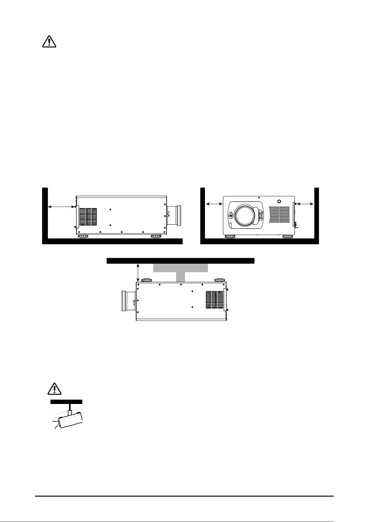
Install the projector in a proper position. Otherwise it may result in a re hazard.
Allowing the proper amount of space on the top, sides, and rear of the projector cabinet
is critical for proper air circulation and cooling of the unit. The illustrations indicates the required distance from the side walls and ceiling.
70cm
30cm
50cm 50cm
Do not cover the ventilation slots on the projector. Heat buildup can reduce the service
life of your projector, and can also be dangerous.
If the projector is unused for an extended period of time, unplug the projector from the
power outlet.
CAUTION ON HANGING FROM THE CEILING
When hanging the projector from the ceiling, keep the air intake vents and the
top clean. If you leave the projector unclean for a long time, the cooling fans can
be clogged with dust, and it may cause a breakdown or a disaster.
DO NOT SET THE PROJECTOR IN GREASE, WET, OR SMOKY CONDITIONS SUCH
AS IN A KITCHEN TO PREVENT A BREAKDOWN OR A DISASTER. IF THE PROJECTOR COMES IN CONTACT WITH OIL OR CHEMICALS, IT MAY BECOME DETERIORATED.
7
Page 8

Safety Instructions
All the safety and operating instructions should be read before the product is operated,
and retain the owner’s manual for later use.
Do not use the equipment near water.
The projector should never be covered with cloth or other materials, and the openings
should not be blocked by placing the projector on unstable surface like a bed, sofa and
rug.
Do not install the equipment near the thermal source, such as the heater, radiator, and
furnace or other equipment that will generate heat (including the amplier).
Do not install the projector near the ventilation duct of air conditioner.
This projector should be operated only from the type of power source indicated on the
marking label. If you are not sure of the type of power supplied, consult an authorized dealer or local power company. Do not allow anything to rest on the power cord.
Do not overload wall outlets and extension cords as this can result in fire or electric
shock.
Do not destroy the safety protection function of polarized or grounding plugs as this can
result in fire electric shock or causing projector damaged. If the provided plug does not
match the outlet, contact an electrician to change the old one.
Prevent the power cord from being treaded or pressed, especially the power cord near
the plug, outlet and the connection between the power cord and the equipment.
Unplug the power cord during a lighting or when the equipment is not used for long periods.
Do not stare directly at the lens when the projector is running.
Do not attempt to service this projector yourself as opening or removing covers may
expose you to dangerous voltage or other hazards. Refer all servicing to qualied service
personnel.
When replacement parts are required, be sure the service technician has used replace-
ment parts specied by the manufacturer that have the same characteristics as the original
part. Unauthorized substitutions may result in re, electric shock, injury to persons or pro-
jector damaged.
The +12V trigger only outputs 12V DC trigger signal. Do not connect to other power input or output. Otherwise, the equipment may be damaged.
Blocking the air vents by dust and leaving the projector uncleaned for a long time may
cause a breakdown, damage the projector or accidents. Please clean or change the lters
regularly. The packaging materials should be kept properly for the use of transportation.
8
Page 9
Installing the Projector in Proper Directions
Use the projector properly in specied positions. Improper positioning may shorten the
lamp life and result in severe accident or re hazard.
This projector can project the picture in upward, downward, or inclined position in perpendicular direction to the horizontal plane.
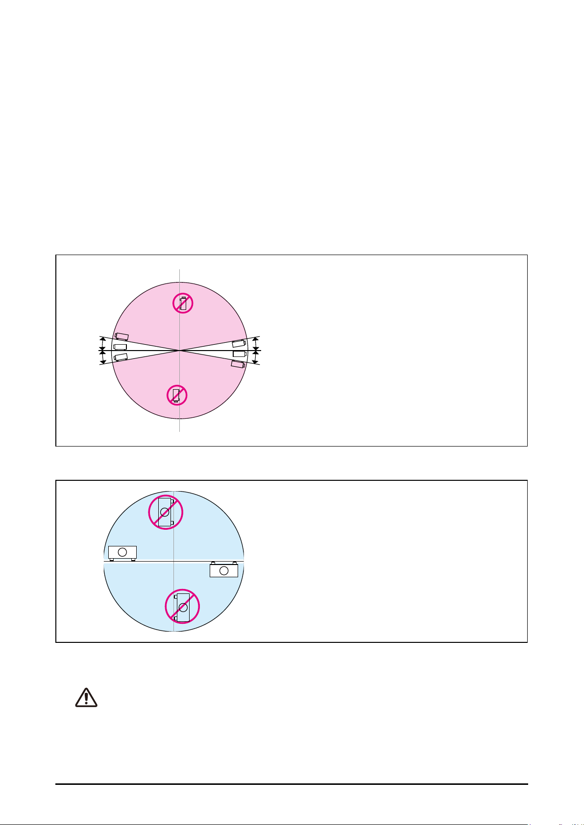
Positioning Precautions
Avoid positioning the projector as described below.
Max
10°
10°
No Portrait Mode
Can’t tilt in this area
Can’t tilt in this area
No Portrait Mode
10°
10°
Max
MaxMax
■ Do not tilt the projector more than 10
degrees from side to side.
■ Not allow the projector in upward or
downward the projection.
■ Do not put the projector on either side
to project an image.
CAUTION ON CEILING MOUNTING
For Ceiling mounting, you need the ceiling mount kit designed for the projector. When the projector is
not mounted properly, it may fail, causing hazards or injury. For details, please consult you dealer. The
warranty dose not cover any damage caused by use of any non-recommended ceiling mount kit or installation of the ceiling mount kit in an improper location.
9
Page 10

Compliance
Federal Communications Commission Notice
This equipment has been tested and found to comply with the limits for a Class A digital
device, pursuant to Part 15 of FCC Rules. These limits are designed to provide reasonable
protection against harmful interference when the equipment is operated in a commercial
environment. This equipment generates, uses, and can radiate radio frequency energy
and, if not installed and used in accordance with the instruction manual, may cause harmful interference to radio communications. Operation of this equipment in a residential area
is likely to cause harmful interference in which case the user will be required to correct the
interference at his own expense.
Do not make any changes or modications to the equipment unless otherwise specied
in the instructions. If such changes or modications should be made, you could be required
to stop operation of the equipment.
Canadian Radio Interference Regulations
This Class A digital apparatus meets all requirements of the Canadian ICES-003.
WARNING:
This is a Class A product. In a domestic environment this product may cause radio interference in
which case the user may be required to take adequate measures.
10
Page 11

AC Power Cord Requirement
The AC Power Cord supplied with this projector meets the requirement for use in the
country you purchased it.
AC Power Cord for the United States and Canada:
AC Power Cord used in the United States and Canada is listed by the Underwriters Laboratories (UL)
and certied by the Canadian Standard Association (CSA).AC Power Cord has a grounding-type AC
line plug. This is a safety feature to be sure that the plug will t into the power outlet. Do not try to
defeat this safety feature. Should you be unable to insert the plug into the outlet, contact your electrician.
AC Power Cord for the United Kingdom:
This cord is already tted with a moulded plug incorporating a fuse, the value of which is indicated on
the pin face of the plug. Should the fuse need to be replaced, an ASTA approved BS 1362 fuse must
be used of the same rating, marked thus ASA. If the fuse cover is detachable, never use the plug
with the cover omitted. If a replacement fuse cover is required, ensure it is of the same colour as that
visible on the pin face of the plug (i.e. red or orange). Fuse covers are available from the Parts Department indicated in your User Instructions.If the plug supplied is not suitable for your socket outlet,
it should be cut off and destroyed.The end of the exible cord should be suitably prepared and the
correct plug tted.
WARNING : A PLUG WITH BARED FLEXIBLE CORD IS HAZARDOUS IF ENGAGED IN A LIVE SOCKET OUTLET.
The Wires in this mains lead are coloured in accordance with the following code:
Green-and-yellow ......... Earth
Blue .............................. Neutral
Brown ........................... Live
As the colours of the wires in the mains lead of this apparatus may not correspond with the coloured
markings identifying the terminals in your plug proceed as follows: The wire which is coloured greenand-yellow must be connected to the terminal in the plug which is marked by the letter E or by the
safety earth symbol or coloured green or green-and-yellow. The wire which is coloured blue must
be connected to the terminal which is marked with the letter N or coloured black. The wire which is
coloured brown must be connected to the terminal which is marked with the letter L or coloured red.
WARNING: THIS APPARATUS MUST BE EARTHED.
THE SOCKET-OUTLET SHOULD BE INSTALLED NEAR THE EQUIPMENT AND EASILY
ACCESSIBLE.
11
Page 12
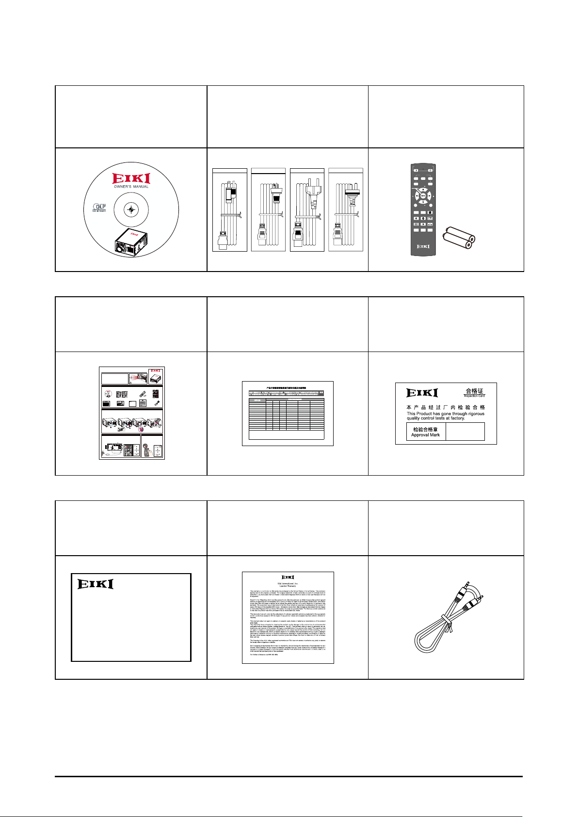
Standard Accessories
3
21
ASPECT
RATIO
AUTO IMAGE
HDBaseTHDMI
RGBHV DVI
VGA
PAUSETEXT
MENU
SHARPNESS
CONTRAST
POWER
INPUT
ON OFF
BRIGHTNESS
FOCUS
FOCUS
ZOOM
ZOOM
LENS CONTROL
4
5
STATUS
3
21
ASPECT
RATIO
AUTO IMAGE
HDBaseTHDMI
RGBHVDVI
VGA
PAUSETEXT
MENU
SHARPNESS
CONTRAST
POWER
INPUT
ONOFF
BRIGHTNESS
FOCUSFOCUS
ZOOM
ZOOM
LENS CONTROL
4
5
POWER
INPUT
>
LED
STATUS
INPUT
ec.
Owner's Manual (CD)
EIP-UJT100
EIP-UJT100
Quick start guide RoHS Card for China QC Pass Card for China
AC Power cord
US Type*2
Euro Type*1
China Type*1
Remote control with batteries
(AA or LR6)
POWER
ON OFF
INPUT
3
241
5
ZOOM
LENS CONTROL
FOCUS FOCUS
ASPECT
MENU
ZOOM
RATIO
AUTO IMAGE
PAUSE TEXT
SHARPN
BRIGHTNESS
CONTRAST
1
PHASE
ADDRESSSWAPPIP
+
+
-
-
Quick Start Guide
• Use this document as a start guide when setting up the
projector.
• For detailed information about installation, setup and
operation for projector, refer to the owner's manual on the
CD-ROM.
Accessories List
Owner's Manual (CD)
AC Power cord
US Type*2 / Euro Type*1 / China Type*1
EIP-UJT100
00
T1
EIP-UJ
RoHS Card
QC Pass Card
for China
for China
产品中有毒有害物质或元素的名称及含量列表
依据中国政府针对“电子信息产品污染控制管理办法"为控制和减少电子信息产品废弃后对环境造成的污染,促进
生产和销售低污染电子信息产品,保护环境和人体健康,仅提供有关本产品可能含有有毒及有害物质如后:
有毒有害物质或元素
部件名称
铅(Pb)汞(Hg)镉(Cd)六价铬(Cr(VI))多溴联苯(PBB)多溴二苯醚(PBDE)
XO O O O O
光机引擎(
铝或铝镁合金)
XO O O O O
镜头
XX O O O O
灯泡
XO O O O O
点灯器
XO O O O O
弹片(快削磷铜)
XO O O O O
风扇组件
OO X O O O
灯泡盖保护开关
OO X O O O
温度开关
XO O O O O
基板组件
XO O O O O
缆线,线材
XO O O O O
电源线
XO O O O O
电源插座组件
XO O O O O
金属件(快削磷铜,铜钉等)
XO O O O O
遥控器
○:表示该有毒有害物质在该部件所有均质材料中的含量均在SJ/T11363-2006标准规定的限量要求以下。
╳:表示该有毒有害物质至少在该部件的某一均质材料中的含量超出SJ/T11363-2006标准规定的限量要求。
备注:鉴于欧盟与中国对于RoHS的不同规定,本投影机产品符合欧盟RoHS指令(电气、电子设备中限制使用某些有害物质指令),本
表中标有"X"的所有部件均为欧盟ROHS指令所允许例外的部件。
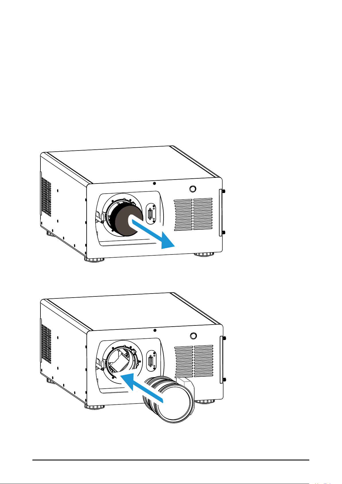
How to install lens
1. Remove the lens hole sponge
from projector.
2. Remove the lens cap (front and back)
on the lens.
1
2
Turn on the projector Turn off the projector
1. Connect the necessary signal cable.
2. Select the correct voltage 115V or 230V.
3. Connect the AC Power Cord.
1
12V Trigger OUT
SYNC
RS-232CHDBaseT
R/C IN
YPbPr IN OUT
LAN
12
5
HDMI INVGA IN G/YB/PbR/Pr DVI-D INHV
INOUT
3G-SDI
MAIN POWER
2
VOLTAGE SELECT
AC IN
4
3
X
Do not look into the lens
while the projector is turned on.
Remote control
Batteries (AA or LR6)
ON OFF
POWER
1
INPUT
LENS CONTROL
4
2
FOCUS FOCUS
ZOOM
3
5
MENU
ZOOM
PAUSETEXT
CONTRAST
ASPECT
1
RATIO
BRIGHTNESS
PHASE
AUTO IMAGE
SHARPN
-
ADDRESSSWAPPIP
+
+
Warranty Card
Warranty Card for USA Wired Remote
for China
3. Insert the lens into lens holder so that the lens motor lead connector is
attached to the socket on the right side of the lens mount.
4. Slowly make the lever a half turn counterclockwise to lock the lens.
Make sure that the lens is fully inserted to the projector.
3
Press and hold the POWER button for 5
4. Secure the power plug by
locking the plug holder clamp.
seconds on the side control or OFF
5. Turn on the AC Power Switch.
button the remote control to turn off the
6. Push the power button to turn
projector.
on the projector.
POWER
ON OFF
MENU
ON
ERROR
6
>
INPUT
LED
HDBaseTHDMI
VGA
3
21
>
RGBHV DVI
>
ENTER
5
4
ZOOM
LENS CONTROL
>
6
STANDBY
FOCUS
FOCUS
INPUT
EIP-UJT100
Quick start guide
Quick Start Guide
• Use this document as a start guide when setting up the
projector.
• For detailed information about installation, setup and
operation for projector, refer to the owner's manual on the
CD-ROM.
Accessories List
Owner's Manual (CD)
RoHS Card
for China
产品中有毒有害物质或元素的名称及含量列表
依
据中国政府针对“电子信息产品污染控制管理办法"为控制和减少电子信息产品废弃后对环境造成的污染,促进
生产和销售低污染电子信息产品,保护环境和人体健康,仅提供有关本产品可能含有有毒及有害物质如后:
部件名称
铅(Pb)汞(Hg)镉(Cd)六价铬(Cr(VI))多溴联苯(PBB)多溴二苯醚(PBDE)
XOOOOO
光机引擎(铝或铝镁合金)
XOOOOO
镜头
XXOOOO
灯泡
XOOOOO
点灯器
XOOOOO
弹片(快削磷铜)
XOOOOO
风扇组件
OOXOOO
灯泡盖保护开关
OOXOOO
温度开关
XOOOOO
基板组件
XOOOOO
缆线,线材
XOOOOO
电源线
XOOOOO
电源插座组件
XOOOOO
金属件(快削磷铜,铜钉等)
XOOOOO
遥控器
○:表示该有毒有害物质在该部件所有均质材料中的含量均在SJ/T11363-2006标准规定的限量要求以下。
╳:表示该有毒有害物质至少在该部件的某一均质材料中的含量超出SJ/T11363-2006标准规定的限量要求。
备注:鉴于欧盟与中国对于RoHS的不同规定,本投影机产品符合欧盟RoHS指令(电气、电子设备中限制使用某些有害物质指令),本
表中标有"X"的所有部件均为欧盟ROHS指令所允许例外的部件。
How to install lens
1. Remove the lens hole sponge
from projector.
2. Remove the lens cap (front and back)
on the lens.
Turn on the projector Turn off the projector
1. Connect the necessary signal cable.
2. Select the correct voltage 115V or 230V.
3. Connect the AC Power Cord.
Cable
EIP-UJT100
EIP-UJT100
IP-UJT100
E
X
Do not look into the lens
while the projector is turned on.
Remote control
Quick start guide
AC Power cord
Quick Start Guide
EIP-UJT100
Batteries (AA or LR6)
US Type*2 / Euro Type*1 / China Type*1
Accessories List
ON
P
OW
ER
1
O
INPU
F
F
LE
4
T
N
2
S
C
O
N
TRO
F
OC
Z
O
3
L
OM
U
S
5
How to install lens
M
E
N
U
EIP-UJT100
Z
PA
F
O
O
OM
US
C
C
U
O
S
E
N
T
R
T
A
1
AS
E
S
RA
B
PECT
XT
P
T
R
AUT
H
T
IGHT
AS
I
O
O
E
N
IM
ES
AG
SHAR
S
E
I
P
PN
S
W
A
-
00
PP
1
T
UJ
-
P
I
Turn on the projectorTurn off the projector
E
A
D
D
R
ESS
+
+
QC Pass Card
Warranty Card
Warranty Card for USAWired Remote
for China
for China
Cable
有毒有害物质或元素
3. Insert the lens into lens holder so that the lens motor lead connector is
attached to the socket on the right side of the lens mount.
4. Slowly make the lever a half turn counterclockwise to lock the lens.
Make sure that the lens is fully inserted to the projector.
4
1
3
2
Press and hold the POWER button for 5
4. Secure the power plug by
locking the plug holder clamp.
seconds on the side control or OFF
5. Turn on the AC Power Switch.
button the remote control to turn off the
6. Push the power button to turn
projector.
on the projector.
1
12V Trigger OUT
SYNC
RS-232CHDBaseT12R/C IN
YPbPrINOUT
LAN
5
HDMI INVGA ING/YB/PbR/PrDVI-D INHV
INOUT
3G-SDI
POWER
ONOFF
MAIN POWER
MENU
ON
MENU
ON
2
5 s
VOLTAGE SELECT
ERROR
6
AC IN
>
ERROR
INPUT
>
4
HDBaseTHDMI
VGA
LED
3
3
21
STATUS
>
RGBHVDVI
>
ENTER
>
5
4
ENTER
ZOOM
>
LENS CONTROL
>
6
STANDBY
FOCUSFOCUS
INPUT
STANDBY
4
MENU
ON
5 sec.
ERROR
>
LED
STATUS
>
>
ENTER
>
STANDBY
INPUT
产品中有毒有害物质或元素的名称及含量列表
依据中国政府针对“电子信息产品污染控制管理办法"为控制和 减少电子信息产品废弃后对环境造成的污染,促进
生产和销售低污染电子信息产品,保护环境和人体健康, 仅提供有关本产品可能含有有毒及有害物质如后:
部件名称
光机引擎(
铝或铝镁合金)
镜头
灯泡
点灯器
弹片(快削磷铜)
风扇组件
灯泡盖保护开关
温度开关
基板组件
缆线,线材
电源线
电源插座组件
金属件(快削磷铜,铜钉等)
遥控器
○:表示该有毒有害物质在该部件所有均质材料中的含量均在SJ/T11363-2006标准规定的限量要求以下。
╳:表示该有毒有害物质至少在该部件的某一均质材料中的含量超出SJ/T11363-2006标准规定的限量要求。
备注:鉴于欧盟与中国对于RoHS的不同规定,本投影机产品符合欧盟RoHS指令(电气、电子设备中限制使用某些有害物质指令),本
表中标有"X"的所有部件均为欧盟ROHS指令所允许例外的部件。
有毒有害物质或元素
铅(Pb) 汞(Hg) 镉(Cd) 六价铬(Cr(VI)) 多溴联苯(PBB) 多溴二苯醚(PBDE)
X O O O O O
X O O O O O
X X O O O O
X O O O O O
X O O O O O
X O O O O O
O O X O O O
O O X O O O
X O O O O O
X O O O O O
X O O O O O
X O O O O O
X O O O O O
X O O O O O
Warranty Card for China Warranty Card for USA Wired Remote Cable
12
Page 13
Optional Accessories
Optional Lenses and Projection Size
Six types of motor-powered projection lens can be an option for EIP-UJT100, the projec-
tion lenses can cover the throw ratio range from 0.67:1 to 6.96:1.
Complete projection lens series as below table
Lens Type
AH-D22010 Fix F/2.5 in center, F/4.5 in corner 14.6 0% 0% 0.67:1
AH-D22020 Fix F/2.5 in center, F/4.5 in corner 23.55 -25% ~ +50% 0% 1.12:1
AH-D22030 1.34 F/2.5 in center, F/4.5 in corner 28.94 – 38.95 -25% ~ +50% ±5% 1.39~1.87 : 1
AH-D21010 1.37 F/2.5 in center, F/4.5 in corner 39.0 – 53.43 -25% ~ +50% ±10% 1.87~2.56 : 1
AH-D23010 1.62 F/2.5 in center, F/4.5 in corner 52.4 – 85.3 -25% ~ +50% ±10% 2.56~4.16:1
AH-D23020 1.67 F/2.5 in center, F/4.5 in corner 84.86 – 142.03 -25% ~ +50% ±10% 4.16~6.96:1
Zoom
Ratio
F#
Focus Length
f (mm)
Lens Shift Range
Throw Ratio
Vertical Horizontal
Projection Size and Distance
Distance unit : m
Lens Type AH-D22010 AH-D22020 AH-D22030 AH-D21010 AH-D23010 AH-D23020
Inch Fixed Fixed Wide Tele Wide Tele Wide Tele Wide Tele
80" 1.2 - - - - - - - - -
90" 1.3 - - - - - - - - -
100" 1.4 - - - 4.0 5.5 - - - -
120" 1.7 - - - 4.8 6.6 - - - -
150" 2.2 3.6 4.5 6.0 6.0 8.3 - - 13.4 22.5
200" 2.9 4.8 6.0 8.1 8.1 11.0 11.0 17.9 17.9 30.0
250" - 6.0 7.5 10.1 10.1 13.8 13.8 22.4 22.4 37.5
300" - 7.2 9.0 12.1 12.1 16.5 16.5 26.9 26.9 45.0
350" - 8.4 10.5 14.1 14.1 19.3 19.3 31.4 31.4 52.5
400" - 9.6 12.0 16.1 16.1 22.1 22.1 35.8 35.8 60.0
450” - 10.9 13.5 18.1 18.1 - 24.8 40.3 40.3 67.5
500" - 12.1 15.0 20.1 - - 27.6 44.8 44.8 75.0
Note:
The values in the tables are approximate and may be slightly different from the actual measurements.
13
Page 14
Overview
Projector contents
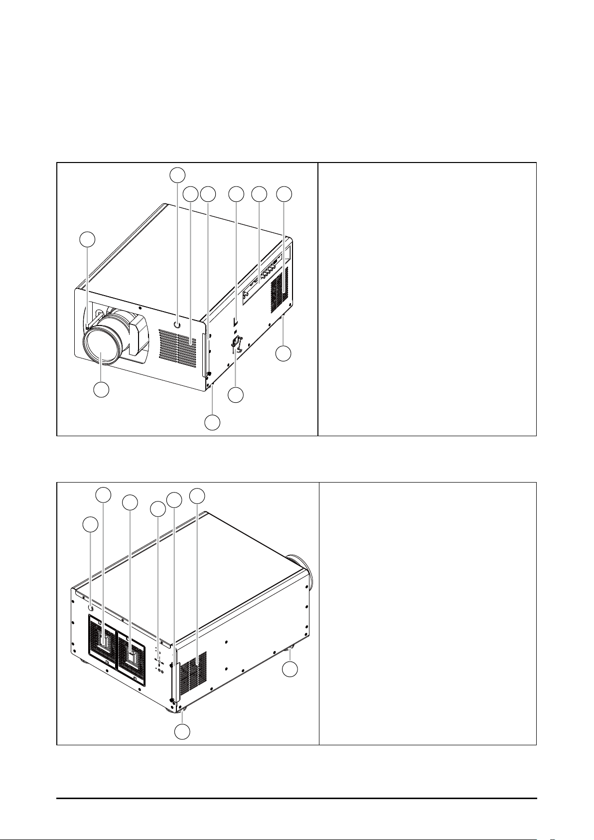
Part Names and Functions
2
3 4 5 6 7
1
Lens Release Trolley
Infrared Remote Receiver(Front)
Air Intake Vent
Filter Cover
AC Power Switch
Terminals and Connectors
Exhaust Vent
Adjustable foot
Power Cord Connector
Lens (Optional)
8
10
9
8
Infrared Remote Receiver(Rear)
2
3
4
6
5
1
Exhaust Vent and Lamp Cover 1
Exhaust Vent and Lamp Cover 2
Control Panel
Filter Cover
Air Intake Vent
Adjustable foot
7
7
14
Page 15
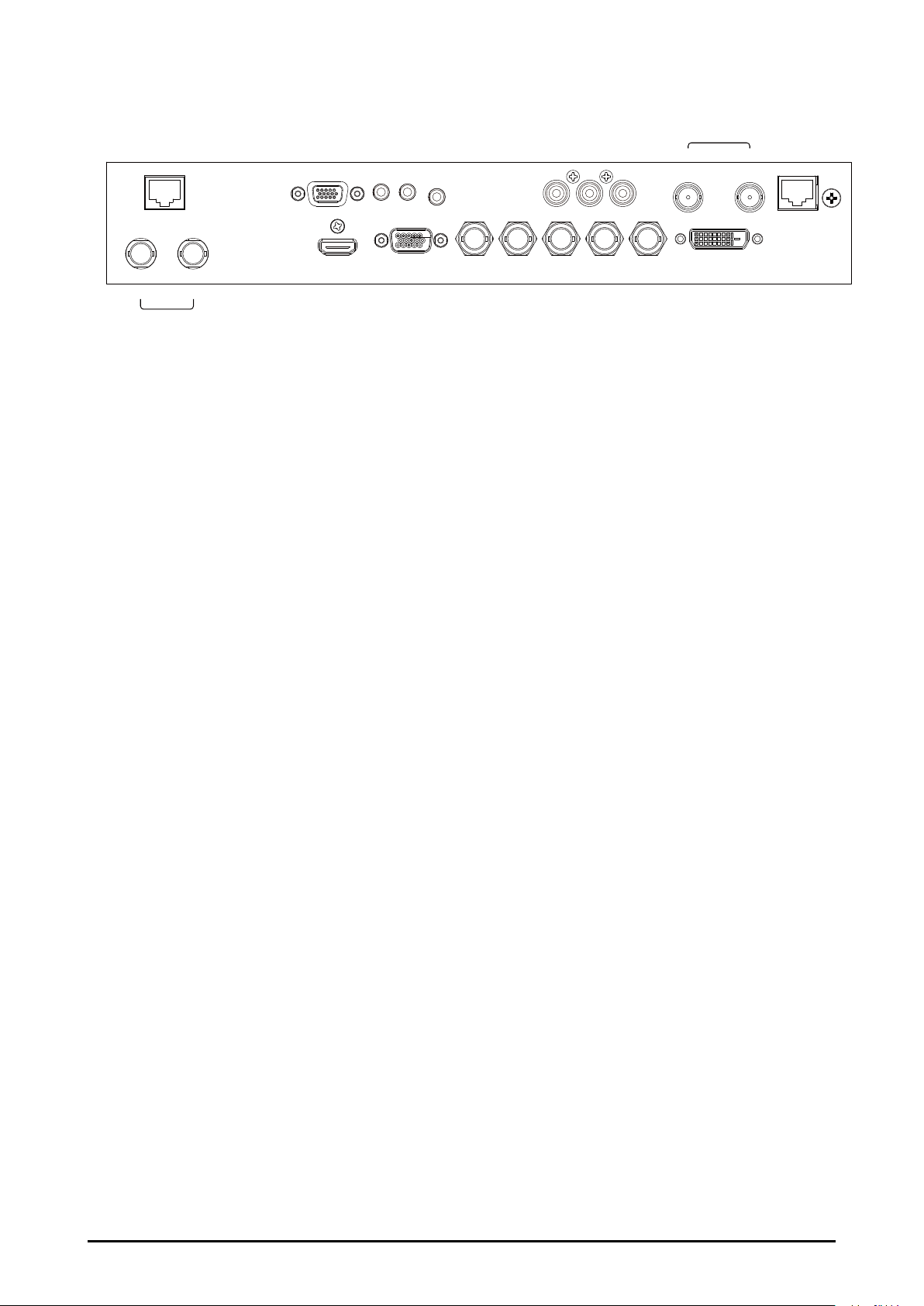
Terminals and Connectors
IN OUT
3G-SDI
RS-232CHDBaseT
12V Trigger OUT
1 2
HDMI IN VGA IN G/Y B/Pb R/Pr DVI-D INH V
R/C IN
Y Pb Pr IN OUT
SYNC
LAN
■ HDBaseT
It can support Full HD uncompressed video transmit from image device compatible with
HDBaseT. Only supports video format over network cable. Data and sound are not supported.
■ RS-232
Connect a RS-232(Not supplied) from the computer to the terminal for controlling the
projector.
■ 12V TRIGGER Out 1 and 2
The TRIGGER terminal provides 12V (+/-1.5) output for screen control
■ R/C IN
Connect the wired remote control to this jack with a remote control cable (supplied).
■ Y/Pb/Pr
Standard and high denition (480i/480p/576i/576p/720p/1080i/1080p) component input,
connects to DVD/HD-DVD/BD player, HD set-top-box or other SD/HD input source.
■ SYNC IN / OUT
IN->From source equipment for informing which eld of signal is the Left-eye or Right-
eye signal.
OUT->From projector and be connected to the 3D SYNC wireless transmitter for synchronizing the projected picture with the 3D glasses.
■ LAN (10/100 BASE-T)
Connect the Ethernet cable to the terminals for controlling the projector.
■ 3G-SDI IN / OUT
Input SDI signals to IN and outputs the SDI signals from OUT.
■ HDMI IN
Connect the HDMI signal from the video device to this terminal.
■ VGA IN
Connect a computer output (Analog D-sub 15-pin type) to this terminal.
■ 5 BNC IN (G/Y, B/Pb, R/Pr, H and V)
Connect the VGA signals or Y/Pb/Pr signals.
■ DVI-D IN (Dual Link)
Connect the DVI-D output on the computer to the terminal, the terminal can support to
HDCP compatible signal.
Note:
Not supported PIP, Warp, and Edge Blend. Can be connected LAN only.
15
Page 16
Control Keys and LED Indicators
source is HDBaseT, HDMI, DVI-D, VGA, Y/Pb/Pr,
appears.
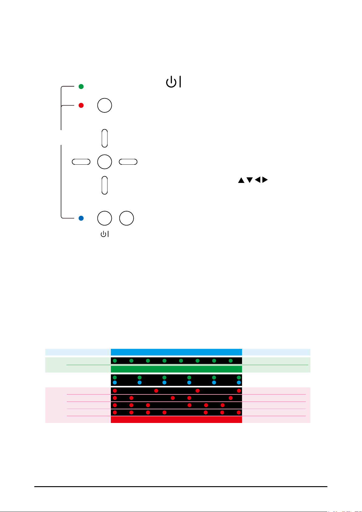
Control Keys
■ (POWER)
ON
MENU
Turn on/off the projector (Press few seconds to
off the projector).
ERROR
>
LED
STATUS
■ INPUT
Select the input source, press the button once to
select next source option, the sequence of the
5 BNC, 3G-SDI.
>
>
ENTER
■ MENU
Press the button to open or close the OSD menu.
■ ARROW BUTTONS (
Use the four buttons to move the cursor on OSD,
>
select the item or adjust the setting
■ ENTER
Use the button to conrm the changes you made
STANDBY
INPUT
and to show ZOOM/FOCUS OSD. When you
press the button again, LENS SHIFT OSD
■ STANDBY (LED-Blue)
The indicator that shows the projector’s standby status.
)
■ ON (LED-Green)
Displays the projector’s power status.
■ ERROR (LED-Red)
Displays the cause of problem (i.e. temperature, fan, lamp or system) that has led to
projector malfunction.
LED Indicators
Standby
ON
Time for lamps replacement Light flash - Green and Blue
ERROR
Cooling / Warm up
Power on / Normal Light on - Green
Over Temperature
Remark:
The time period of each step in the above LED blinking pattern is 0.5 second, e.g., for “Cooling /
Warm up” state, the green LED will ON for 0.5 second, and then OFF 0.5 second, and then repeat the
above LED pattern
Standby
Lamp fail
Lamp door open
Fan Fail
System Errow
Light on - Blue
Light flash - Green
Light flash - Red
Light flash twice - Red,
Light flash 3times - Red
Light flash 4times - Red
Light on - Red
16
Page 17
Remote Control
POWER
ON OFF
1
INPUT
3
4
6
8
10
12
13
15
17
19
HDBaseTHDMI
RGBHV DVI
4
LENS CONTROL
FOCUS
MENU
PAUSE TEXT
CONTRAST
ZOOM
ZOOM
BRIGHTNESS
1
PHASE
VGA
21
3
5
ASPECT
RATIO
AUTO IMAGE
SHARPNESS
ADDRESSSWAPPIP
FOCUS
2
5
7
9
11
14
16
18
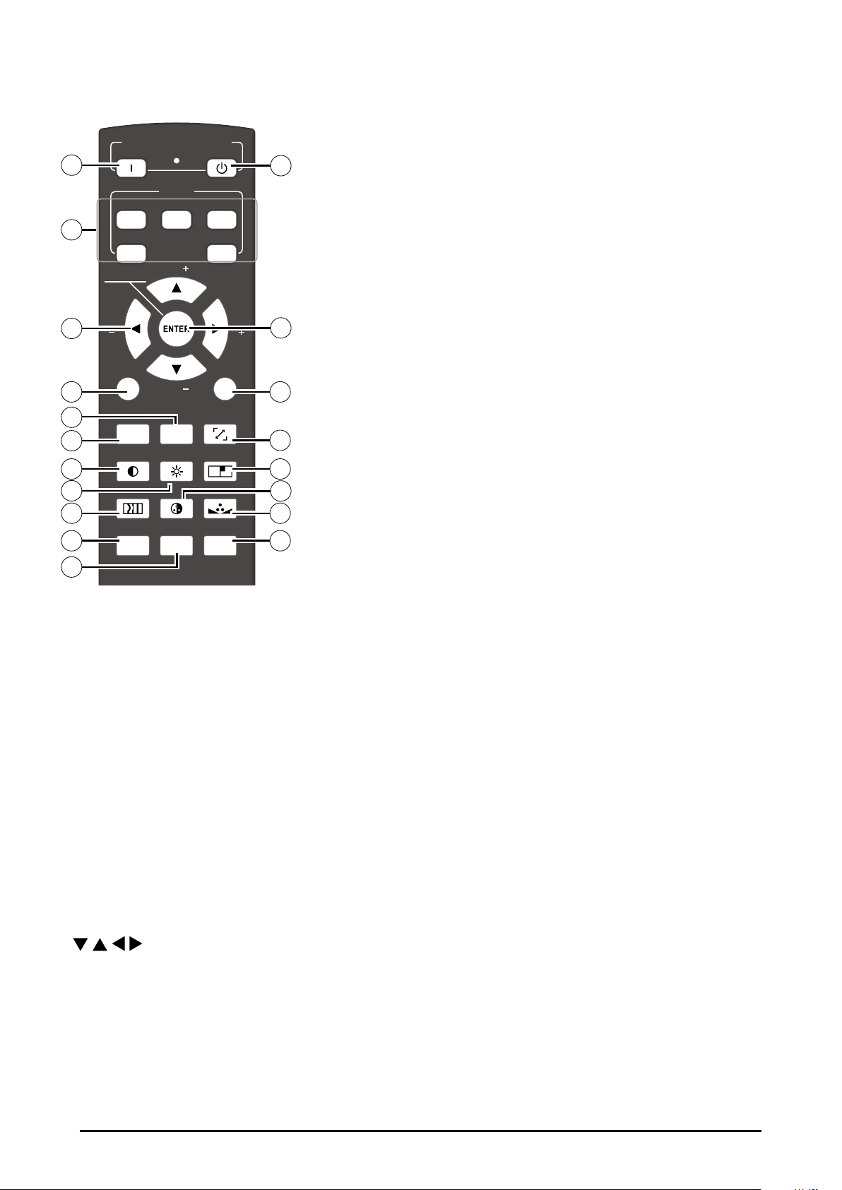
-> show Lens shift OSD.
6. MENU
Open and close the OSD menu.
7. ASPECT RATIO
Select the aspect ratio settings.
8. TEXT
When TEXT is set to ON, the user will be
able to operate the OSD Menu normally.
When TEXT is set to OFF, only ON, OFF, 1~5,
SWAP, PIP, PAUSE will function normally;
pressing any other buttons will not access
the OSD Menu.
9. AUTO IMAGE
Resync the picture. (The adjustments also
apply to PIP input).
10. PAUSE (SHUTTER)
Open/Close the shutter.
11. SHARPNESS
Adjust picture sharpness and clarity.
12. CONTRAST
Adjust the picture contrast.
13. BRIGHTNESS
Adjust the picture brightness.
1. ON
Press a few seconds to power on the projector.
2. OFF
Press a few seconds to off the projector
3. 1,2,3,4 and 5
Hotkeys for different picture source. Factory
default setting is below. The settings of hotkeys are changeable. Refer to Page 54
Button 1~5
1 = HDMI
2 = HDBaseT
3 = VGA
4 = RGBHV, Y/Pb/Pr
5 = DVI (3D DVI)
Note: DVI(3D DVI), Refer to page 37.
4.
Use these buttons to make your selection or
congure, adjust conguration or toggle between picture displays.
5. ENTER
*Conrm the OSD change.
*Press 1 time directly
-> show Zoom/Focus OSD.
*Press 2 times directly
14. --This function not available for this model.
15. PHASE
When the picture ickers, doubles, distorts
or appears to be wavy, press this button to
adjust.
16. ---
This function not available for this model.
17. PIP
Use this button to display or disable PIP.
18. ADDRESS
*Only 2 addresses are possible*
Press and hold the ENTER button and press
Address button until the remote control panel
ashes once (approximately 5 seconds) to
change the receiving address of the remote
control. If you use one remote control to operate two different projectors, you can assign
different address for the two projectors so
that when you operate projector A, projector
B will not be affected.
19. SWAP
Use this button to switch the sources of picture PIP display.
17
Page 18
Note:
*In most situations, you can simply point the remote control at the screen which will reect the IR signal from the remote back toward the IR receiver on the projector. In some cases, however, ambient
light may prevent this. If so, try again.
*If the effective range of the remote control decreases, or it stops working, replace the batteries with
new ones.
*The remote control may fail to operate if the infrared remote sensor is exposed to bright sunlight or
uorescent lighting.
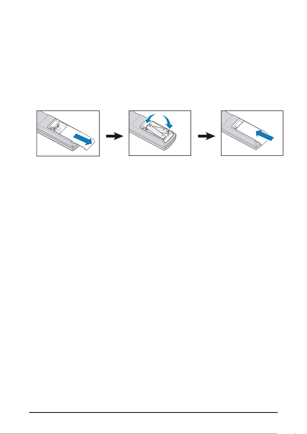
Remote Control Battery Installation
123
1. Slide the battery cover to remove it.
2. Install two AA(2) batteries with the correct polarity.
3. Put back the cover.
Note:
*Make sure that the battery polarities are correct when installing the batteries.
*Do not mix an old battery with a new one or different types of batteries.
*Avoid contact with water or liquid.
*Do not expose the remote control to moisture or heat.
*Do not drop the remote control.
*If you will not use the remote control for a long time, remove the batteries to avoid damage from battery leakage. Please wipe the remote control clean and install new batteries if the battery is leaked.
*Dispose of used batteries according to the instructions or your local disposal rule or guideline.
18
Page 19
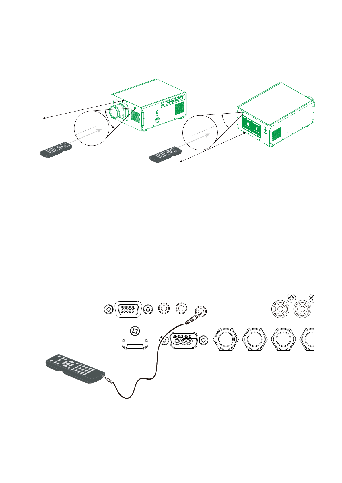
Remote Control Receivers and Operation Range
H
Infrared Remote Receivers are provided on the front and rear cover. Point the remote
control toward the projector, then press the buttons. Maximum operating range for the remote control is about 12 meters and ±30 degrees.
12m
±30°
±30°
12m
Note:
When hanging the projector from the ceiling, point toward the Infrared Remote Receiver which is lo-
cated farther away from the uorescent light.
Wired Remote Control
The remote control can be used as a wired remote control. Wired remote control helps
you use the remote control outside the operating range. Connect the remote control and
the projector with the remote control cable (supplied). If the remote control is connected to
the cable, the remote control does not emit signal.
RS-232C
HDMI IN VGA IN G/Y B/Pb R/Pr
12V Trigger OUT
1 2
R/C IN
Y Pb
Wired Remote cable length = 5m(16.4 feet)
19
Page 20
Installation
Lens Installation
Before setting up the projector, install Projection Lens on the projector.
Before installation, check where the projector is used and prepare a suitable lens. For
the details, contact the sales dealer where you purchased the projector.
Install and change the projector Lens:
1. Remove the sponge.
2. Insert the lens and ensure the lens touches the lens holder. Carefully the lens motor
board must insert into the machine's jack.
20
Page 21
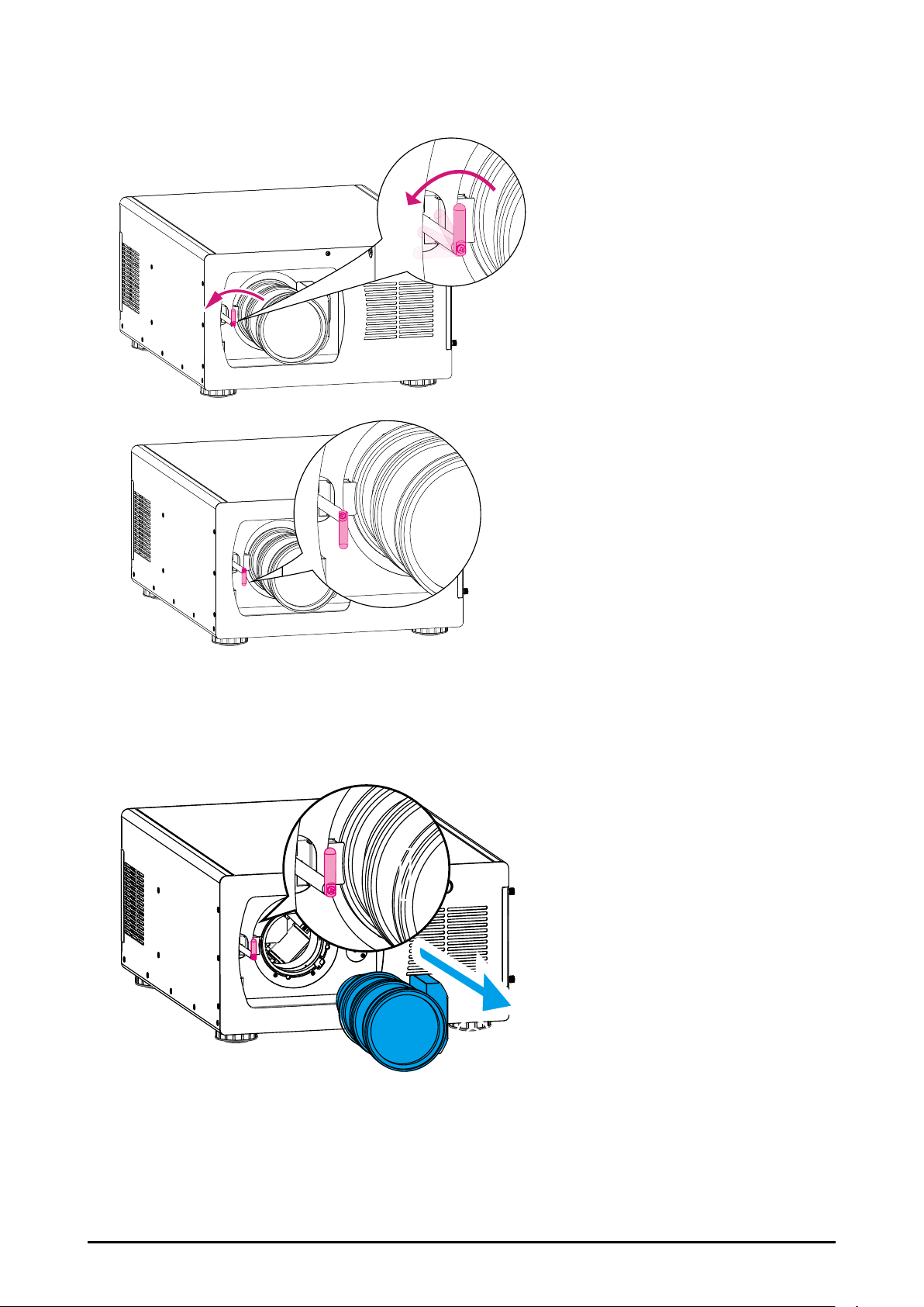
3. Please conrm whether the lens is properly inserted. Then rotate the lever counter-
2
clockwise to lock the lens.
Remove Lens
1. Rotate the lever clockwise to unlock the lens then take out the lens.
1
21
Page 22
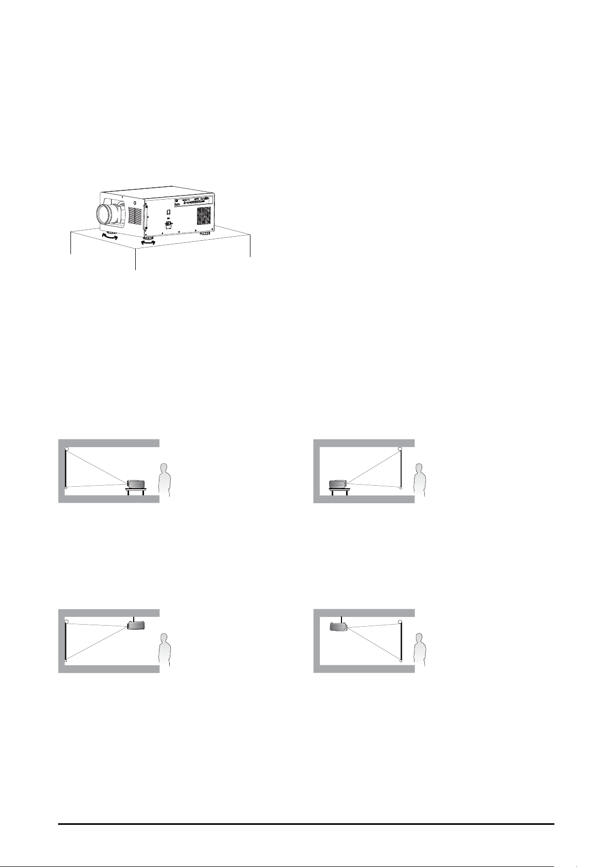
Positioning Projector
Picture Level and Pitch Adjustment
The projection angle is adjustable up to 5 degrees upward and downward respectively
by rotating front and rear. To raise the projector, rotate the front feet clockwise, rotate the
rear feet clockwise to lower the projector.
Adjusting the Picture Orientation
This projector is designed to be installed in one of four possible installation locations.
Take into consideration the size and position of the screen, the location of a suitable power outlet, rest of equipment. Open the OSD -> ADVANCED -> Rear Projection or Ceiling
Mode to the preferred projection setting.
Front : Select this location with the projector placed in front of the screen. This is the
most common way to position the projector.
Ceiling + Front : Select this location with
the projector mounted on the ceiling in front
of the screen. Ceiling mount kit is required.
Please consult your dealer for more details.
Rear : Select this location with the projector placed behind the screen. Note that
a special rear projection screen is required.
Ceiling + Rear : Select this location with
the projector mounted on the ceiling behind
the screen. Note that Ceiling mount kit and
special rear projection screen are required.
Note:
Ceiling installation must be done by a qualied professional, It is not recommended you install the projector yourself. For more information, please contact your dealer.
Only use the projector on a solid, level surface. Serious injury and damage can occur if the projector
is dropped.
Do not cover the vents on the projector. Proper ventilation is required to dissipate heat. Damage to the
projector will occur if the vents are covered.
22
Page 23
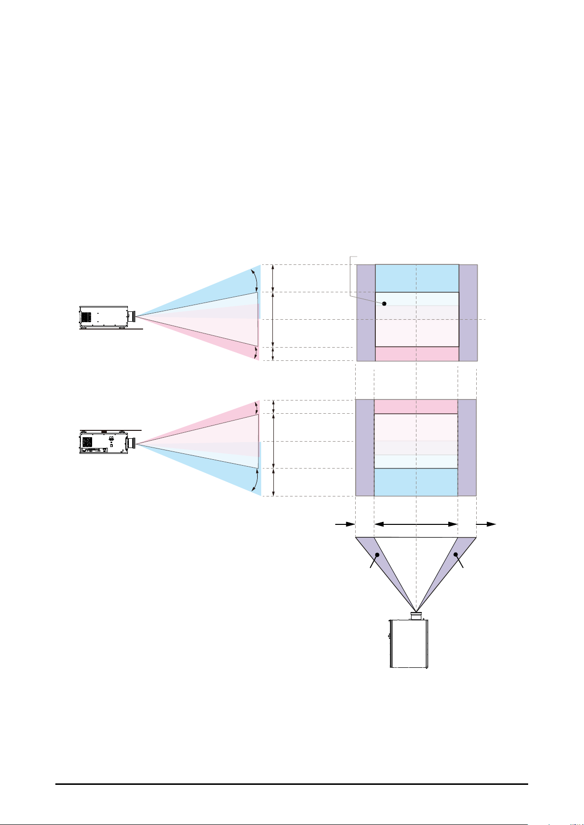
Lens Shift Adjustment
Projection lens can be moved up, down, right and left with the motor-driven lens shift
function. This function makes the positioning of images easy on the screen. Lens shift is
generally expressed as a percentage of the image height or width, see below illustration
Vertical / Horizontal Lens Shift
■ Vertical: The lens can be moved 50% (0.5V) upward, and 25% (0.25V) downward. So if
the screen height is 50”, and use a 80”x50” screen, you can move the image upward no
more than 25” or downward no more than 12.5”.
■ Horizontal: The lens can be moved 10% (0.1H) left or Right, If you
use a 80”x50” screen, you can move the image left or right no more 8”
Desk-Front Projection
Height of projected image
Max
0.5V
Verticial Shift (Up)
Projected image height V
Verticial Shift (Down)
Max 0.25V
Normal projection position
Ceiling Mount-Front Projection
Verticial Shift (Down)
AC
VOLTAGE SELECT
AC SWITCH
SDI
HDMI VGA G/Y B/Pb R/Pr DVI Dual LinkH V
IN
OUT
III
IR Ext.
Y Pb Pr IN OUT
10/100 BASE-T
SYNC
12V Trigger
HD CONNECT/LAN
HDBaetT RS-232
Height of projected image
Verticial Shift (Up)
Max 0.25V
Projected image height V
Max
0.5V
0.1H
Shift to Left
1H
Width of projected image
0.1H
Shift to Right
Note:
This is a general example of lens shift. Lenses vary in their shift capabilities. No particular lens or projector is used in this example.
When the lens is shifted beyond the described range of operation, the screen edges may become
darker or the images may become out of focus.
23
Page 24

Connecting to Computer Signal
Cables used for connection
■ DVI Cable (DVI-D 24 pin)
■ BNC Cable(BNCx5)
■ VGA Cable (D-Sub 15 pin)
■ HDMI Cable (19 pin Type A)
■ RS-232C (D-Sub 9pin): Connect a PC or theater control/automation system to the RS-
232 port on the projector. Use a standard, 9-pin serial cable, wired straight-through.
NOTE:
Accessories not including the cables of DVI, BNC, VGA, HDMI and RS-232C.
IN OUT
3G-SDI
RS-232CHDBaseT
HDMI Cable BNC CableVGA Cable
12V Trigger OUT
1 2
HDMI IN VGA IN G/Y B/Pb R/Pr DVI-D INH V
R/C IN
Signal Output
Y Pb Pr IN OUT
SYNC
DVI Cable
LAN
Laptop computer
24X DVD RW
Desktop
Computer
24
Page 25

Connecting to Video Signal
Cable used for connection
■ HDBaseT (RJ-45 8pin)
■ Video Cable (3BNCx1, 5BNCx1)
■ DVI Cable (DVI-D 24pin)
■ SDI Cable (BNC 1pin)
■ HDMI Cable (19pin Type A)
NOTE:
Accessories not including the cables of HDBaseT, Video, DVI, SDI and HDMI.
RS-232CHDBaseT
IN OUT
3G-SDI
SDI Out HDMI Output
Blu-ray Player
HDMI IN VGA IN G/Y B/Pb R/Pr DVI-D INH V
12V Trigger OUT
1 2
R/C IN
Y Pb Pr IN OUT
Component Video Output
(B/Pb G/Y R/Pr)
Component Video output equipment
(Such as high-definition TV source)
SYNC
DVI Output
LAN
25
Page 26

Trigger connection
B/Pb R/Pr
Y
If your projection system includes a projector screen. Screen cover or other 12V Trigger
equipment, please connect such device/equipment to the projector’s 12V Trigger output as
illustrated. After you have done so, your screen will lower automatically whenever you turn
on your projector for your convenience. (Maximun 200mA for Trigger1 or 2)
IN OUT
3G-SDI
RS-232CHDBaseT
HDMI IN VGA IN G/Y
12V Trigger OUT
1 2
R/C IN
26
Page 27

Stereo DVI Connection
Connect the Stereo DVI to a stereo 3D source - it is usually a computer with 3D Graphics card and 3D applications.
IN OUT
3G-SDI
12V Trigger OUT
RS-232CHDBaseT
HDMI IN VGA IN G/Y B/Pb R/Pr DVI-D INH V
1 2
R/C IN
Y Pb Pr IN OUT
3D Glasses
IR Emitter
SYNC
LAN
LAN Connection
If you want to control the projector via the internet web. You can use LAN(RJ-45) to connect the computer, server and projector. Key in the correct IP Address or the computer host
name which same as the projector's host name then you can remote control the projector
by internet.
R/C IN
Y Pb Pr IN OUT
G/Y B/Pb R/Pr DVI-D INH V
27
SYNC
LAN
Page 28

Connecting to wired remote controller
Pb
You can use the remote control as a wired remote control.
Wired Remote cable length = 5m(16.4 feet)
IN OUT
3G-SDI
RS-232CHDBaseT
HDMI IN VGA IN G/Y B/Pb R/Pr
12V Trigger OUT
1 2
R/C IN
Y
28
Page 29

Connecting the AC Power Cord
This projector uses nominal input voltages of 100-240 VAC. It is designed to work with
single-phase power systems having a grounded neutral conductor.
1. Connect the necessary signal cable.
2. Select the correct voltage 115V or 230V.
3. Connect the AC Power Cord.
4. Secure the power plug by locking the plug holder clamp.
To reduce the risk of electrical shock, do not plug into any other type of power system.
If you are not sure of the type of power being supplied, consult your authorized dealer or
service center. Connect the projector with all peripheral equipment before turning on the
projector.
VOLTAGE SELECT
AC IN
Select 115V or 230V
Note:
Unplug the AC power cord or turn off the MAIN ON/OFF Switch when the projector is not in use and
the projector is in stand-by mode, it consumes a little electric power.
29
Page 30

Basic Operation
ENTER
INPUT
ERROR
STANDBY
>
>
>
>
LED
STATUS
ERROR
MENU
ON
>
>
LED
STATUS
3
21
ASPECT
RATIO
AUTO IMAGE
HDBaseTHDMI
RGBHV DVI
VGA
PAUSE TEXT
MENU
POWER
INPUT
ON OFF
FOCUS
FOCUS
ZOOM
ZOOM
LENS CONTROL
4
5
POWER
INPUT
ON OFF
ERROR
MENU
ON
>
LED
3
21
ASPECT
RATIO
AUTO IMAGE
HDBaseTHDMI
RGBHV DVI
VGA
PAUSE TEXT
MENU
SHARPNESSCONTRAST
POWER
INPUT
ON OFF
BRIGHTNESS
FOCUS FOCUS
ZOOM
ZOOM
LENS CONTROL
4
5
Turning On the Projector
1. Complete peripheral connections (with a computer, Blu-ray Player, etc.) before turning
on the projector. 2. Connect the projector’s AC power cord into an AC outlet and turn on
the MAIN ON/OFF Switch. 3. Press the "POWER" button on the side controller or On but-
ton on the remote control. The LAMP indicator ashes green and the cooling fans start to
run, it will take few seconds to display the projected image on the screen.
Turn Off the Projector
1. Press and hold the POWER button for 5 seconds on the side control or OFF button the
remote control to turn off the projector.
2. If the LAMP indicator lights bright and the POWER indicator turns off. After the projec-
tor is turned off, the cooling fans operate. You cannot turn on the projector during this
cooling down.
3. When the projector has cooled down enough, the POWER indicator lights green and
then you can turn off the MAIN ON/OFF Switch, wait until the projector is completely
cooled. Then unplug the AC power cord from the AC outlet.
30
Page 31

Selecting an Input Source
ENTER
INPUT
STANDBY
>
>
>
3
21
HDBaseTHDMI
RGBHV DVI
VGA
POWER
INPUT
ON OFF
FOCUS FOCUS
ZOOM
LENS CONTROL
4
5
3
21
ASPECT
RATIO
AUTO IMAGE
HDBaseTHDMI
RGBHV DVI
VGA
PAUSE TEXT
MENU
SHARPNESSCONTRAST BRIGHTNESS
FOCUS
FOCUS
ZOOM
ZOOM
LENS CONTROL
4
5
When you turn on the projector, it switches to the last selected input and waits for a valid signal. Press the “INPUT” on the remote control or control panel to switch to an input
source directly. Refer to page 17 button 1-5 for default input setting and these setting
are changeable, Refer to Page 54 Button 1~5
Selecting a Aspect Ratio
Press ASPECT to adjust the aspect ratio of the image. For detail information, refer to
Page 40 Aspect Ratio
31
Page 32

How to Operate the OSD Menu
ERROR
MENU
ON
>
LED
1
3
21
ASPECT
RATIO
AUTO IMAGE
RGBHV DVI
PAUSE TEXT
MENU
SHARPNESSCONTRAST BRIGHTNESS
FOCUS
FOCUS
ZOOM
ZOOM
LENS CONTROL
4
5
The projector has an On-Screen Display (OSD) that allows you to adjust the image and
change settings.
OSD Operation
1. Press the MENU button to open the OSD.
2. Press ▲ or ▼ to select a title menu.
3. Press ◄ or ► to select an item.
4. Press the Enter, and ▲ or ▼ to change or adjust the selected item.
5. Press the MENU in the monent move to upper menu.
Following steps are a basic way for operating the OSD.
The selected item will be highlighted.
32
Page 33

Changing the OSD Language
The product can display the menus in English, French, Spanish, German, Portuguese,
Simplify Chinese, Traditional Chinese, Japanese or Korean.
Press the “MENU” to open the OSD. Go to SYSTEM and select Language then press
the Enter. You can select a language there.
33
Page 34

OSD Tree
Main Menu Sub-menu
Input Selection HDMI
Color Space Auto
Input Locking Auto
MAIN
Auto Power Off On
Auto Power On On
No Signal Logo
Auto Image Adjust Off
HDBaseT
VGA
Y/Pb/Pr
RGBHV, Y/Pb/Pr
3G-SDI
3D DVI
REC709
REC601
RGB-PC
RGB-Video
48Hz
50Hz
60Hz
Off
Off
Blue
Black
White
Auto
Always
Main Menu Sub-menu
Contrast 0-200
Brightness 0-200
Sharpness 0-200
Noise Reduction 0-200
Color Temperature 3200K
Input Balance Black Balance Offset
PICTURE
Aspect Ratio 5:4
Timings H Total
Auto Sync Execute
Overscan Off
Main Select HDMI
PIP Select HDMI
LAYOUT
PIP Position Top Left
PIP On
5400K
6500K
9300K
Native
Red Offset
Green Offset
Blue Offset
White Balance
Red Gain
Green Gain
Blue Gain
4:3
16:10
16:09
1.88
2.35
Letterbox
Native
Unscaled
H Start
H Phase
V Start
Crop
Zoom
HDBaseT
VGA
Y/Pb/Pr
RGBHV, Y/Pb/Pr
3G-SDI
HDBaseT
VGA
Y/Pb/Pr
RGBHV, Y/Pb/Pr
3G-SDI
Top Right
Bottom Left
Bottom Right
Split L-R
Off
34
Page 35

Main Menu Sub-menu
Main Menu Sub-menu
LAMPS
ADVANCED
Power ECO
Normal
Custom Level
Mode Single
Dual
High Altitude On
Off
Custom Power Level 78.3%~100%
Lamp1 Status On / Off
Lamp2 Status On / Off
Lamp1 Run Time XX HRS
Lamp2 Run Time XX HRS
Rear Projection On
Off
Ceiling Mode On
Off
Lens Control Zoom / Focus
Shift H/V
Dynamic Contrast On
Off
Gamma 1.8
2.0
2.2
2.35
2.5
DICOM SIM.
Test Pattern Color Bar
Cross hatch
Half scanning
Red
Green
Blue
White
Black
Red
Green
Blue
Gray Scale
Color Gamut Native
EBU
SMPTE
Custom
ADVANCED
Custom Color
Gamut
Center Lens Execute
Warp Keystone
Blanking Top
Edge Blending Status
Red x
Red y
Green x
Green y
Blue x
Blue y
Cyan x
Cyan y
Magenta x
Magenta y
Yellow x
Yellow y
White x
White y
Reset
Rotation
Pincushion / Barrel
Top Left Corner
Top Right Corner
Bottom Left Corner
Bottom Right Corner
Reset
Bottom
Left
Right
Reset
White Level
Black Level
Reset
Adjust Lines
35
Page 36

Main Menu Sub-menu
Main Menu Sub-menu
SYSTEM
IR Address 1
2
Eco Network Power On
Off
Network Network Status
IP Address
Subnet Mask
Gateway
DHCP
Network Setting
IP Address
Subnet Mask
Gateway
DHCP
Menu Position Top Left
Top Right
Bottom Left
Bottom Right
Center
Start Up Logo On
Off
Start Up Chime On
Off
Button 1 HDMI
HDBaseT
VGA
Y/Pb/Pr
RGBHV, Y/Pb/Pr
3G-SDI
3D DVI
Button 2 HDMI
HDBaseT
VGA
Y/Pb/Pr
RGBHV, Y/Pb/Pr
3G-SDI
3D DVI
Button 3 HDMI
HDBaseT
VGA
Y/Pb/Pr
RGBHV, Y/Pb/Pr
3G-SDI
3D DVI
Button 4 HDMI
HDBaseT
VGA
Y/Pb/Pr
RGBHV, Y/Pb/Pr
3G-SDI
3D DVI
SYSTEM Button 5 HDMI
HDBaseT
VGA
Y/Pb/Pr
RGBHV, Y/Pb/Pr
3G-SDI
3D DVI
Trigger 1 Auto
5:4
4:3
16:10
16:09
1.88
2.35
Letterbox
Native
Unscaled
Trigger 2 Auto
5:4
4:3
16:10
16:09
1.88
2.35
Letterbox
Native
Unscaled
Auto Source On
Off
Language English
Français
Español
Deutsch
Português
简体中文
繁體中文
日本語
한국의
Model
Serial Number
Software Version
Active/PIP Source
Pixel Clock
Signal Format
H/V Refresh Rate
SERVICE
Lamp 1 Run Time x HRS
Lamp 2 Run Time x HRS
Lamp Hour Reset Reset Lamp 1
Reset Lamp 2
Projector Run Time
Blue Only On
Off
Factory Reset
36
Page 37

OSD Operation-MAIN
Input Selection
You can select an input source.
■ HDMI: HDMI input.
■ HDBaseT: HDBaseT input.
■ VGA: Analog RGB.
■ Y/Pb/Pr: YPbPr input.
■ RGBHV, Y/Pb/Pr: Analog RGB / Component.
■ 3G-SDI: Uncompressed digital video from a serial connection (coaxial)
■ DVI-D (3D DVI): Use this DVI dual link to connect to a stereo 3D source – it is usually a
computer with 3D Graphics card, and 3D applications.
Below information is the DVI-D (3D DVI) format:
Signal Type Resolution Frame rate
1920x 1080 120Hz V V
1920x 1080 100Hz V V
PC
1920x1200 120Hz V V Reduced Blanking
1920x1200 100Hz V V Reduced Blanking
1920x 1080 60Hz V
1920x1200 60Hz V Reduced Blanking
DVI
single-link
DVI
3D Reference
dual-link
Note:
Signals are not supported for EIP-UJT100, if it is not in the table.
37
Page 38

Color Space
This function allows you to change component and VGA input sources. You can select
different color space for different color performance.
■ Auto: The default setting is Auto.
HDMI: If the Auxiliary Video Information (AVI) contains color space and/or range data,
the EIP-UJT100 uses that information to switch to corresponding color space.
RGB: If Hsync or Vsync signals are present, the projector will switch to RGB-PC color
space.
Component: For SDTV and EDTV resolutions, the EIP-UJT100 uses the REC601 color
space. For all other resolutions REC709 is used.
In most cases, the Auto setting determines the correct color space. If it does not, you can
use a specic color space. Choose one of the following:
■ REC709: sets the color space matrix to that dened in ITU-R BT.709.
■ REC601: sets the color space matrix to that dened in ITU-R BT.601.
■ RGB-PC: uses RGB color space and sets black at 0,0,0 RGB and white at 255,255,255
RGB, assuming an 8-bit image.
■ RGB-Video: uses RGB color space and sets black at 16,16,16 RGB and white at
235,235,235, assuming an 8-bit image, to correspond to the luminance values dened
in digital component standards.
Input Locking
Use this function to lock a source to an internal sync signal (Auto, 48Hz, 50Hz, or 60Hz).
Auto setting locks the sync signal to the current source.
Auto Power Off
The default value is OFF. If you set it ON, the projector will automatically shut down after
20 minutes without input signal.
Auto Power On
The default value is Off. If you set it to ON, the projector will automatically start up when
it is connected to the AC power.
No Signal
Use this function to specify the content or color to be displayed on the blank screen
when no input signal is available. You can choose from Logo, Blue, Black, White. The default value is Logo.
38
Page 39

Auto image Adjust
Set the timing of the Auto image Adjust function for(Resync on page 41) below 3
modes:
■ Off: Auto image function is not executed.
■ Auto: Use the parameters that users used last time.
The adjusted parameters are stored in the projector, 5 resolution data for each digital
and analog inputs. If there is no record of parameters, auto image function will be
executed.
■ Always: Auto image function is executed automatically when the input source is
selected.
OSD Operation-PICTURE
Contrast
Use ◄ or ► to adjust the contrast of the projected image. Adjustable value: 0 to 200.
Note:
Brightness and Contrast controls are interactive. The screen change to one may require a subtle
change to the other in order to achieve the optimum setting.
Brightness
Use ◄ or ►to adjust the level of black in the image to increase or decrease image
brightness. Adjustable value: 0 to 200.
Sharpness
Use ◄ or ► to adjust the adjustment of sharpness primarily changes the value of high
frequency detail. Adjustable value: 0 to 200.
39
Page 40

Noise Reduction
Use◄ or ►to adjust the noise of the projected image. This function is suitable for the
elimination of image noise from interleaving SD input. Generally speaking, reducing image
noise will lower the value of high frequency detail and make the image appear more mellow. Adjustable value: 0 to 200.
Color Temperature
Use ◄ or ► to adjust the color temperature 3200K, 5400K, 6500K, 9300K or Native of
the projected image.
This refers to the control of color imbalance in the darker areas of the projected image.
It is recommended that you use an external test image with many areas of dark and gray
colors (i.e. an image of 30IRE-window). If you notice minimal amount of red, green or blue
in the gray areas, adjust the offset of the corresponding color accordingly. This function will
shift the entire color spectrum for the whole image and change its brightness.
Input Balance
To adjust Black and White balance.
Black Balance : Adjust R/G/B color offset of image that will control dark areas.
White Balance : Adjust R/G/B color gain of image that will control bright areas.
Aspect Ratio
This function allows user to adjust the picture’s Aspect ratio.
When Native input is 16:10, the images as following is the result of picture’s aspect ratio
for your preference.
Original Aspect Ratio of output
Aspect Ratio of output
screen 1.88
Original Aspect Ratio of output
screen 5:4
Aspect Ratio of output
screen 2.35:1
screen 5:4
Aspect Ratio of output
screen 4:3
Aspect Ratio of output
screen Letter Box
Aspect Ratio of output
screen 4:3
Aspect Ratio of output
screen 16:10
Aspect Ratio of output
screen Native
Aspect Ratio of output
screen 16:10
Aspect Ratio of output
screen 16:9
Aspect Ratio of output
screen Unscaled
Aspect Ratio of output
screen 16:09
Aspect Ratio of output
screen 1.88
Aspect Ratio of output
screen 2.35:1
Aspect Ratio of output
screen Letter Box
40
Aspect Ratio of output
screen Native
Aspect Ratio of output
screen Unscaled
Page 41

Timings
■ H Total: Use ◄► to adjust the horizontal total.
Use this function to adjust the clock frequency of pixel sampling (horizontal pixel
frequency of the analog input source generated by the ADC). If you notice ickering or
vertical lines in the picture, it means that the pixel sampling frequency is insufcient. You
can use this function to adjust the frequency to achieve consistent picture quality.
■ H Start: Use ◄► to adjust the projected picture’s horizontal position.
If the projected picture is not at the center of the screen (i.e. shifted to right or left) and
ends up being cropped, use this function to adjust the picture’s horizontal position.
The following picture is an example of test picture from an external signal source:
Left
Right
■ H Phase: Use ◄► to adjust the projected picture’s phase.
Use this function to adjust the phase of pixel sampling clock (relative to input signal).
Should the picture still icker or show noise (i.e. edges on texts) after optimization,
adjust phase accordingly.
■ V Start: Use ◄► to adjust the projected picture’s vertical position. If the projected
picture is not at the center of the screen (i.e. shifted up or down) and ends up being
cropped, use this function to adjust the picture’s vertical position.
DownUp
It is recommended that when adjusting the picture, the horizontal total should be adjusted
before the horizontal phase. However, if the picture still ickers even after you have adjusted
both, try lowering the picture noise.
Note:
H Total and H Phase only support for Analog signal (Y/Pb/Pr, VGA, BNC). Can’t adjust when the
input is Digital signal
Auto Image
When Auto Image was selected, press ENTER to execute the automatic picture adjustment function.
By executing this function, the projector will resync the picture. Use this function when
the picture source is unstable or when you notice deterioration in picture quality and the
projector will automatically adjust the picture size, phase and timing. (The adjustment also
applies to PIP input source).
41
Page 42

OSD Operation-LAYOUT
Overscan
Some programs may display the edges of the image. Use this function to hide the edge
by choosing one of the following two options.
Off Crop Zoom
5:4
4:3
16:10
16:9
42
Page 43

1.88
(Sub)
2.35
Letter Box
Native
Unscaled
Off Crop Zoom
Main Select
When you want to project PIP picture, use this function to specify the picture source for
the PIP picture. This function is identical to Input Selection; for more information.
Main
PIP
Source
HDMI HDBaseT VGA Y/Pb/Pr RGBHV, Y/Pb/Pr 3G-SDI
HDMI - v v v -
HDBaseT - v v v PIP
(SUB)
VGA v v - - v
Y/Pb/Pr v v - - v
RGBHV, Y/Pb/Pr v v - - v
3G-SDI - - v v v
Note:
DVI-D(3D DVI) has not supported PIP.
PIP Select
Main
Press ENTER to display available sources for the sub picture then select a source. Note
that unavailable input source of sub-menu are gray out and can not be selected. The available input source of sub picture is as below combination list.
43
Page 44

PIP Position
Top Left
2
Bottom Left
2
Top Right
Use this function to select the location of the PIP window to Top left, Top Right, Bottom
Left, Bottom Right, or Split L-R.
2
1
Bottom Right Split L-R
1
1
1
2
2 1
PIP
If you wish to display PIP picture, you can make the configuration here. By choosing
"ON", you will see two windows on the projected picture; the larger one is the primary picture and the smaller one is the sub picture. By choosing "OFF", the PIP function will be disabled and you will only see a single picture window.
OSD Introduction – LAMPS
44
Page 45

POWER
Default value is Normal.
■ ECO: The wattage of the lamp will be at 360W. If the surrounding environment is
sufciently dark or if you do not require intense brightness, you can set the lamp to Eco
mode to prolong its usage life.
■ Normal: The wattage of the lamp will be at 465W. If the projection environment requires
brighter picture, you can set the lamp to Normal for the highest projection brightness.
■ Custom Level: If the picture brightness at Eco mode is too dark for you and the Nor-
mal mode gets too bright, you can set it to custom level to specify the power of the lamp
yourself to make ne adjustments to the brightness of the projected picture. You could
encounter situations where the picture from projector A being brighter than projector B.
When this occurs, you can use this function you could encounter situations where the
picture from projector A being brighter than projector B. When this occurs, you can use
this function to ne tune the brightness of the two projectors to achieve consistent picture brightness. To access this function, go to the OSD Menu → LAMPS → Power
(Custom Level) → Custom Power Level and adjust accordingly.
Note:
ECO is automatically selected between 35~40°C(95~104°F)
Mode
Use ◄ or ►function to select single or dual lamp mode.
High Altitude
Use this function to switch the projector’s cooling fan for high-altitude circumstances.
You can set it to Off or On. The default setting is Off.
Under normal circumstances, the projector will operate normally with this function set to Off. If you were to operate the projector in environment of excessive heat
or in areas of high altitude, the projector may automatically shut down due to overheat. When this happens, you can enable this function by setting it to On to force the
cooling fan to work at a higher speed to regulate the temperature inside the projector.
Note:
High altitude region refers to area with elevation over 5000 feet
Custom Power Level
Use this function to fine-tune the brightness. You can set power range from 78.3% to
100%.
45
Page 46

Lamp 1 Status
Displays the Lamp 1 status.
Lamp 2 Status
Displays the Lamp 2 status.
Lamp1 Run Time
This function is limited to display purposes to inform the user of Lamp1's total run time.
Lamp2 Run Time
This function is limited to display purposes to inform the user of Lamp2's total run time.
Note :
You can choose to use one single lamp. The projector will automatically determine the usage hours
for lamp1 and lamp2 and choose the lamp with lower hours for the operation.
OSD Introduction – ADVANCED
46
Page 47

Rear Projection
Default setting is Off
Select "ON" when you set the projector to rear projection mode. Refer to Page 22 Ad-
justing the Picture Orientation
Ceiling Mode
Default setting is Off
When you have set up the projector for ceiling mode (hung from the ceiling in reverse),
please set it to ON. For more information on different modes of projection, refer to Page
22 Adjusting the Picture Orientation
Lens Control
Use this function to display Lens Control window, press ◄, ►, ▲ or ▼ to adjust lens
shift, Zoom or Focus. Press Enter button to switch window for Zoom & Focus adjustment
or Lens Shift adjustment.
Dynamic Contrast
When activated this function, the projector will dynamically adjust the picture contrast
from the beginning of the projection until the content has ended.
Gamma
You can choose from ve different gamma settings (1.8, 2.0, 2.2, 2.35, 2.5 and Dicom
sim) on the projector to affect picture darker, brighter.. The projector's default gamma value is at 2.2.
Every setting has precisely dened phases to display all primary colors (red, green, blue)
and secondary colors (yellow, cyan, magenta) in millions of pixels. Changing any number
in the setting will change the resulting color and rearrange the color "triangle".
47
Page 48

Test Pattern
Select this function to display test pattern, press ◄ or ► once to display the last or next
pattern. To exit, press ► several times until the test patterns disappear.
Color Gamut
You can choose from the following color gamma to create different color presentation in
the projected picture.
■ Native: Choose this to apply the projector's native color gamut
■ EBU: Choose this to apply the EBU color gamut; it is primarily suited for input devices
using PAL, 576i, 576p and so forth
■ SMPTE: Choose this to apply the SMPTE color gamut; it is primarily suited for input
devices using NTSC, 480i, 480p and so forth.
■ Custom: Choose this to customize the color gamut as your preference through serial
commands.
Custom Color Gamut
This allows user adjust primaries(Red, Green, Blue), secondaries(Cyan, Yellow, Magen-
ta), and white point independently to select the color performance that user prefer.
Center Lens
You can select Execute to center the lens when after series of lens shift operations.
48
Page 49

Warp
-20 200
-100 1000
Use this function to correct image distortion.
Note:
DVI-D(3D DVI) has not supported warp.
■ Keystone: Use ◄ or ► to correct horizontal distortion. Press▲ or ▼to correct vertical
distortion.
The adjustable value
H: -350 ~ 300
V: -32 ~ 32
■ Rotation: Press◄ or ►to rotate the projected image.
The adjustable value is from -20 to 20.
P
■ Pincushion / Barrel: Use this function to correct pincushion or barrel distortion. The
adjustable range is from -100 to 100 steps. Press ◄ to correct pincushion distortion, ►
to correct barrel distortion.
P
P
P
P
P
49
Page 50

(Corner Keystone)
%ODQNLQJ
■ Top Left Corner
Press ▲▼◄►to correct top left corner
image distortion.
X: -192~192
Y: -120~120
■ Top Right Corner
Press ▲▼◄►to correct top right corner
PICTURE
X: -192~192
Y: -120~120
■ Bottom Right Corner
PICTURE PICTURE
image distortion.
Press ▲▼◄►to bottom right corner image
distortion.
PICTUREPICTURE
PICTURE
X: -192~192
Y: -120~120
■ Bottom Left Corner
Press ▲▼◄►to bottom left corner image
PICTURE PICTURE
distortion.
X: -192~192
Y: -120~120
■ Reset: Set all values to 0.
Blanking
Use this function to adjust the edges of the image and hide unwanted sections of the
screen up to 30%.
$UHD
50
Page 51

■ Top: Use◄► to adjust the top blanking area on the projected image.
Adjustable from 0 to 360
■ Bottom: Use ◄► to adjust the bottom blanking area on the projected image.
Adjustable from 0 to 360
■ Left: Use ◄► to adjust the left blanking area on the projected image.
Adjustable from 0 to 534
■ Right: Use ◄► to adjust the right blanking area on the projected image.
Adjustable from 0 to 534
■ Reset: Set all the values to 0.
Edge Blend
Edge blend function allows multiple projector images to be seamlessly overlapped. To
use this function, Edge Blend must be enabled on both projectors.
■ Status: Press ENTER to select ON or OFF. The function must be set to ON in order to
enable the function of Edge blend. If the function is set to OFF, the function of Edge
blend is disabled.
■ White Level: White level is to used to set the overlapped area at the four sides for
blend in multi-projection application. Adjusted lines, when enabled, will be shown for
indicating the overlapped area boundary. Press▲▼◄► to adjust the white level at Top,
Bottom, Left, Right directions on the projected picture.
As shown in the below drawing, the white level area is the overlap area of the projected picture 1 and
the projected picture 2. The white level lines that is set where the other projector last pixels ends.
■ Black Level: The outward boundaries of overlapping edges might appear brighter than
the rest of the image due to the lumen at the inactive DMD display area. The purpose
of black level is compensate the non overlap area vs the overlap area. It increases the
black level of non overlap area .It is used to adjust the black level at Top, Bottom, Left,
Right directions on the projected pictures.
After selecting and conguring the black level adjustment area, each of the primary
colors Red, Green, Blue can be adjusted to increase to a higher black level
independently, or optionally All colors together can be adjusted to increase to a higher
black level simultaneously.
Note:
The function combination of Black Level adjustment , 4 Corners and blend along comers is not available.
Note:
DVI-D (3D DVI) has not supported Edge Blend.
51
Page 52

White Level Lines
Image 1
Area for black
level increase
adjustment
A black image is required to connect to the multiple projectors to be blended for the black level adjustment. For projector projecting Image 1, Set the adjustment line of the black level to the position where
the in active DMD's of another projector ends, for example: Adjust black level of projector corresponding to Image 1 to match the black level of inactive DMD display area of another projector. And performing the same adjustment on the projector corresponding to Image 2.
■ Reset: Set all the value to 0.
■ Adjust Lines: When the function is ON, there will be adjust lines on the picture in order
to easily adjust multiple pictures. Press ▼▲◄► on the remote control to adjust the
position of the lines on the picture.
Increase
black level
{
Black Level
Width (Right)
Image 2
White Level
Width(Right)
Note:
When the "ON" is selected, the adjustment lines appear for blending adjustment. After the adjustment
has been done, do not forget to select "OFF" to erase the green lines.
52
Page 53

OSD Introduction – SYSTEM
IR Address
If control two projectors with one remote control, you can set one projector IR Address
code to “1” and “2” for the other projector. You can control two projectors with the same remote control just need to change the IR Address 1 or 2.
Eco Network Power
Selecting the ECO network disable the LAN function.
When this function set to ON, the projector will turn off the power that control the the LAN
board. So you can't operate the projector remotely over a network at the standby mode.
If set to OFF, you won't conserve power but can control the projector remotely over a
network.
53
Page 54

Network
To control the projector via network, after connecting the network cables for a PC and
the projector, you can use this OSD function to view the relevant network information (such
as IP Address, Subnet Mask, Gateway and DHCP) of the projector. Please congure the
PC to be connected to the projector with a proper IP address with the same subnet mask,
gateway as the projector. The default IP address of the projector is 192.168.0.100. The
network settings of the projector can only be changed through the web-page control or serial commands.
To control the projector via network, please connect to the projector via a web browser
with the IP address shown on the OSD menu System -> Network.
Menu Position
Set the OSD pop on the screen's position. The default setting is “Center”.
Top Left
Bottom Left Bottom Right Center
Top Right
Start Up Logo
Use◄► select on or off of the start up logo.
Start Up Chime
Set it to On to have the projector play a sound effect during start up; when it is set to off,
the projector will not play any sound effect to indicate start up.
Button 1~5
Use this function to set the picture source for each corresponding button.
For example, if you have assigned Button 1 as HDMI and Button 2 as VGA, when you
press
you press
1
on the remote control, the projector will show the picture from HDMI. And when
2
on the remote control, the projector will switch to the picture from VGA.
54
Page 55

You can choose different input sources on the projector, namely: HDBaseT, HDMI,
DVI-D, VGA, Y/Pb/Pr, 5 BNC, 3G-SDI.
Factory default setting refer to page 17 button 1-5.
Note:
DVI-D (3D DVI) has not supported PIP, Warp, Edge Blend.
After factory reset, the input button will be back to default.
Trigger 1, 2
The projector comes with one set of Trigger output. You can congure one devices connected to the projector via the trigger port to be automatically turned on when the projector
is on. There will be a 2-3 second delay prior to activation to prevent operation of this function when the user is choosing an aspect ratio.
■ 5:4: Outputs 12V of power on Trigger when Aspect Ratio is set to 5:4.
■ 4:3: Outputs 12V of power on Trigger when Aspect Ratio is set to 4:3.
■ 16:10: Outputs 12V of power on Trigger when Aspect Ratio is set to 16:10.
■ 16:9: Outputs 12V of power on Trigger when Aspect Ratio is set to 16:9.
■ 1.88: Outputs 12V of power on Trigger when Aspect Ratio is set to 1.88.
■ 2.35: Outputs 12V of power on Trigger when Aspect Ratio is set to 2.35.
■ Letterbox: Outputs 12V of power on Trigger when Aspect Ratio is set to Letterbox.
■ Native: Outputs 12V of power on Trigger when Aspect Ratio is set to Native.
■ Unscaled: Outputs 12V of power on Trigger when Aspect Ratio is set to Unscaled.
■ Auto: Outputs 12V of power on Trigger automatically.
Auto Source
When set to ON the projector will automatically determine the source of input every time
it is turned on so that the user will not have to make the selection on the OSD Menu.
Setting the function off will require the user to specify source of picture input on the OSD
Menu in order for the projector to display the intended picture.
Note:
This function is not available when the input source is 3D DVI.
Language
Set the OSD language. Refer to Page 33 Changing the OSD Language
55
Page 56

OSD Introduction – SERVICE
The functions covered in this unit relate to the display of some basic information about
the projector.
Note:
Memory of the custom timing les will be erased in the Factory Reset operation.
Model
The designated model number of the projector.
Serial Number
The designated serial number of the projector.
Software Version
The version of software installed on the projector.
Active/PIP Source
Displays the current Active/PIP sources.
Pixel Clock
Displays the pixel clock of the current input signal.
56
Page 57

Signal Format
Displays the format of the current input signal.
H/V Refresh Rate
Displays the horizontal and vertical refresh rates for the current image.
Lamp 1 Run Time
Display the lamp 1 usage time.
Lamp 2 Run Time
Display the lamp 2 usage time.
Lamp Hour Reset
Use this function to reset the hours for lamp1 or lamp2 to zero.
Note:
After replacing the lamp, remember to reset the lamp hours to ensure the accuracy of lamp hours displayed in the OSD Menu.
Projector Run Time
Displays the projector's total operating hours.
Blue Only
This function displays only blue color to facilitate the process of image inspection for a
service personnel.
Factory Reset
Restore the congurations in the OSD Menu back to the factory default.
Note that this function will not apply to items including no signal, network, Projector
control, startup Logo, language, High Altitude mode and lamp hours.
Note:
When Factory Reset is executed, all source memories created by the projector will be erased.
57
Page 58

Maintenance and Care
Lamp Replacement
The life cycle of ordinary projection lamp typically lasts for 2000 hours before requiring
replacement (different lamp congurations will affect lamp life). From the OSD Menu, you
can check how long the lamp has been used. You should also replace the lamp when the
projected image gets noticeably darker. Contact your local dealer to purchase new certied
lamps.
1. Turn off the projector and unplug the power cord. Leave the projector for approximately
30 minutes to cool enough before removing the lamp module for replacement.
Note:
When you turn off the projector, the lamp inside the projector will still be very hot (approximately 200 ~
300°C). If you attempt to replace the lamp without allowing the projector to cool, you could risk scalding yourself. This is why you should wait for no less than 30minutes for the lamp to cool down in order
to perform the replacement safely.
2. Loosen the screws on the fan units.
3. Remove the fan units.
4. Use a screw driver to loosen the screws
as shown in the illustration.
Lamp1 Lamp2
5. Grasp the metal rod on the lamp cover
and pull the lamp out.
58
Page 59
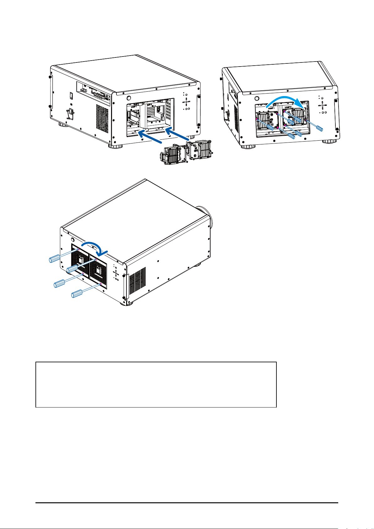
6. Insert the new lamp, tighten the three screws and make sure the lamp is rmly secured
to prevent the lamp from shaking or poor contact.
7. Install the lamp units and tighten the screws on them.
8. Reconnect power to the projector and reset the lamp usage timer. Refer to
Page 46 Lamp1 Run Time
Page 46 Lamp2 Run Time
ORDER REPLACEMENT Lamp
Replacement Lamp can be ordered through your dealer.
When ordering a lamp, give following information to the dealer.
Replacement lamp P/N: AH-D31010
59
Page 60

Filters Replacement
The interval of the lter replacement is affected by the dustiness. Check the lters peri-
odically for better performance.
Note:
Dirty lter may reduce the air owing into the projector and the temperature in the projector may rise
as a result. This may activate the protection mechanism or damage the components. Suggest to
change the lter each 2000 hours.
Check, clean and replace the lter periodically.
1. Loosen the screws on the lter cover.
2. Remove the lter cover and take out the old lters.
60
Page 61

3. Insert the new lters into the machine.
White side
3243411700
Black side
4. Tighten the screws on the lter cover.
x
White side
x
Black side
3243270701
ORDER REPLACEMENT Filter
Replacement lter can be ordered through your dealer.
When ordering a lter, give following information to the dealer.
Replacement Filter P/N: 3243270701(Rear), 3243411700(Front)
61
Page 62

Appendix
Technical Specication
Model EIP-UJT100
Display Type DLP
Native Resolution WUXGA (1920 x 1200)
Maximum Resolution WUXGA (1920 x 1200)@60Hz
Lamp Life and Type 2000hours(Normal 465W), 2500hours(ECO 360W)
Aspect Ratio Native, Unscaled, 5:4, 4:3, 16:10, 16:9, 1.88, 2.35 and Letterbox
Lens Shift Range V(-25%~50%), H(+/-10%)
Keystone Correction Vertical: +/-20° Horizontal:+/-35°
Synchronization
Edge Blending Yes (built-in)
Video Compatibility
I/O Connection Ports
Projection Method Table Top, Ceiling Mount (Front or Rear)
Dimensions (W x D x W) 550x505x250mm (21.7”x19.9”x9.8”)
Weight (Without Lens) 37kg (81.4lbs)
Power Supply AC 100-240V, 50/60Hz
Power Consumption
Standard Accessories
Optional Accessories
SDTV(480i/576i), EDTV (480p/576p), HDTV (720p, 1080i/p), NTSC/NTSC 4.43
HDMIx1, RGB/H/Vx1, YPbPrx1, VGAx1, DVI-Dx1, SDIx1, HDBaseTx1, SYNC INx1,
SYNC OutX1, R/C INx1, 12V-Triggerx2, RS-232x1, LANx1
Input Voltage Normal Mode ECO Mode
220V 1140W 895W
110V 1230W 955W
AC Power Cord(USA) x2, AC Power Cord(EU) x1, AC Power Cord (China) x1
Remote Control x1, Owner's Manual (CD) x1, Quick Start Guide x1
RoHS Card for China x1, QC Pass Card for China x1, Warranty Card for China x1
Warranty Card for USA x1, Battery AA x2, Wired Remote Cable x1
Vertical: 23.98 - 120 Hz
Horizontal: 15.63 - 91.15kHz
PAL B/G/H/I/ M/N 60, SECAM
Standby: 5W (LAN ON)
Interchangeable Lens (x6)
Replacement Lamp
Replacement Filter
62
Page 63

Product Outline Dimension
EIP-UJT100
633.4
499.8
270
105
160
220
Mounting bracket screw hole (M6)
These screw holes are used to mount the
projector to its designated mounting bracket
using 6 M6x15 screws. The dimensions of the
screw holes are shown in the picture below.
63
Page 64

Support Timing List
Signal Format Resolution
640x480 59.94 V V V
640x480 74.99 V V V
640x480 85 V V V
800x600 60.32 V V V
800x600 75 V V V
800x600 85.08 V V V
848x480 47.95 V V V
848x480 59.94 V V V
1024x768 60 V V V
1024x768 75 V V V
1024x768 85 V V V
1280x720 47.95 V V V
1280x1024 60.02 V V V
PC
Apple Mac
NTSC
PAL
SECAM SECAM (M) 50
SDTV
EDTV
HDTV
new for SDI
1280x1024 75.02 V V V
1280x1024 85.02 V V V
1600x1200 60 V V V
1920x1080 47.95 V V V
1680x1050 59.94 V V V
1920x1200 50 V V V
1920x1200 59.94 V V V
1920x1200 60 V V V
1400x1050 60 V V V
1366x768 60 V V
1440x900 60 V V
1280x768 60 V V
1280x800 60 V V
1280x960 60 V V
640x480 66.59 V V
832x624 74.54 V V
NTSC
{M, 4.43)
PAL
(B, G, H, I)
PAL (N) 50
PAL (M) 59.94
RGBS 50
480i 59.94 V V
1440x480i 60 V V V V
1440x576i 50 V V V V
576i 50 V V
480p 59.94 V V V V V V V V
576p 50 V V V V V V V V
1035i 60 V V V V V V V V V
1080i 50 V V V V V V V V V
1080i(Aus) 50 V V V V V V V V V
1080i 59.94 V V V V V V V V V
1080i 60 V V V V V V V V V
720p 50 V V V V V V V V V
720p 59.94 V V V V V V V V V
720p 60 V V V V V V V V V
1080p 23.98 V V V V V V V V V
1080p 24 V V V V V V V V V
1080p 25 V V V V V V V V V
1080p 29.97 V V V V V V V V V
1080p 30 V V V V V V V V V
1080p 50 V V V V V V V V V
1080p 59.94 V V V V V V V V V
1080p 60 V V V V V V V V
1080sf 30 V
1080sf 25 V
Frame
Rate
59.94
50
3 RCA 5BNC
Y-Pr-Pb Y-Pr-Pb RGB
HD15-
RGBHV
HD15
YUV
HDMI
YUV YUV YUV
8 bit 10 bit 12 bit
SDI
V
64
Page 65

SDI Format
p
r
p
r
p
r
p
r
p
r
p
r
p
r
p
r
p
r
p
r
p
r
p
r
p
r
A
r
A
r
A
r
p
r
p
r
p
r
A
Timing SDI Link mode Signal Standards
NTSC SD SMPTE 259M-C 270Mb
PAL SD SMPTE 259M-C 270Mb
1035i60 HD SMPTE 292M 1.5Gb
1080i59 HD SMPTE 292M 1.5Gb
1080i60 HD SMPTE 292M 1.5Gb
1080P30 HD SMPTE 292M 1.5Gb
1080P25 HD SMPTE 292M 1.5Gb
1080i50 HD SMPTE 292M 1.5Gb
1080P24 HD SMPTE 292M 1.5Gb
720P60 HD SMPTE 292M 1.5Gb
720P50 HD SMPTE 292M 1.5Gb
1080Sf25 HD SMPTE 292M 1.5Gb
1080Sf30 HD SMPTE 292M 1.5Gb
1080P50 3G Level
1080P59 3G Level
1080P60 3G Level
1080P50 3G Level B SMPTE 424M 3Gb
1080P59 3G Level B SMPTE 424M 3Gb
1080P60 3G Level B SMPTE 424M 3Gb
Test Cable: Belden 1694
SMPTE 424M 3Gbps YCbC
SMPTE 424M 3Gbps YCbC
SMPTE 424M 3Gbps YCbC
s HD YCbC
s HD YCbC
s HD YCbC
s HD YCbC
s HD YCbC
s HD YCbC
s HD YCbC
s HD YCbC
s HD YCbC
s HD YCbC
s HD YCbC
s YCbC
s YCbC
s YCbC
Color
Encode
s SDYCbC
s SDYCbC
Sampling
Structure
4:2:2 10
4:2:2 10
4:2:2 10
4:2:2 10
4:2:2 10
4:2:2 10
4:2:2 10
4:2:2 10
4:2:2 10
4:2:2 10
4:2:2 10
4:2:2 10
4:2:2 10
4:2:2 10
4:2:2 10
4:2:2 10
4:2:2 10
4:2:2 10
4:2:2 10
Bit Depth
DVI dual-link for 3D
Signal Type Resolution Frame rate
1920x 1080 120Hz V V
1920x 1080 100Hz V V
PC
1920x1200 120Hz V V Reduced Blanking
1920x1200 100Hz V V Reduced Blanking
1920x 1080 60Hz V
1920x1200 60Hz V Reduced Blanking
DVI
single-link
DVI
3D Reference
dual-link
65
Page 66

Projector Control via LAN
The projector supports to control the projector through the network. Before using this
function, please set up the network conguration of your personal computer.
1. Set up network conguration.
The default IP address of the projector is 192.168.0.100, please follow below steps to
set the network conguration.
Connect RJ-45 cable from PC to the LAN connector on the projector.
RS-232C
12V Trigger OUT
1 2
HDMI IN VGA IN G/Y B/Pb R/Pr DVI-D INH V
R/C IN
Y Pb Pr IN OUT
SYNC
LAN
2. Set up Internet Protocol (TCP/IP) Properties in your PC as below:
Recommended PC setting
IP Address : 192.168.0. 99.
Subnet : 255.255.255.0
Default settings for the projector
IP Address : 192.168.0.100
Subnet : 255.255.255.0
66
Page 67

Open a web browser on your PC and type the IP address of the projector
(192.168.0.100), IP conguration will be shown on the web page.
Set the IP address and subnet mask and click SAVE to conrm the conguration. Projec-
tor Web Control will show below message for conrmation.
“The projector IP will be changed and the connection to the projector will be lost, do you
want to continue ?
Select "Yes" to conrm the changes, "No" to cancel.
Note:
Make sure the IP address of the projector and PC are in the same network group.
67
Page 68

Using Projector Web Control
■ Source/General
Use this page to control the general settings of the projector such as power on/off,
source….etc.
Note:
If projector control option is selected to RS232, the web control will be interrupt. Network control has
to be enabled from the projector’s OSD menu before connecting to projector web control.
■ Image Setting
Click arrows to adjust the image settings such as Brightness, Sharpness…etc. on the
web page.
68
Page 69

■ Lens Adjustments
This page allows you to adjust Zoom, Focus and Lens shift. The operation is similar to
control the projector by the remote control or control panel on the projector, click arrows
to adjust the settings.
■ Geometry Adjust
Click the arrow buttons to adjust Blanking, Warp, Four Corner, and click the option
to select the aspect ratio setting. Click Reset option to reset Blanking or Warp to the
default setting.
69
Page 70

■ Edge Blend
Click Status option to enable or disable Edge Blend function. When Edge Blend is
disabled, the other options are unavailable and N/A is shown on the column. The other
options are available only when Edge Blend is enabled.
■ Advance Control
This page allows you to select color temperature or adjust black balance or white
balance. Click the option to select Color Temp. or arrow button to adjust the setting.
70
Page 71

■ Conguration
Use this page to modify the networking setting such as IP address, Subnet, Gateway
and DHCP. Make sure the IP address of the projector and PC are in the same network
group. For example, 192.168.0.X. Whereas X must contain a different value.
If the network provides DHCP service, you can enable DHCP client. IP Address, Subnet,
and Gateway will be assigned by DHCP service. Please contact with your network
administration for more details.
■ Diagnostics
Advance Diagnostics
This page is to diagnose the projector. Okay is displayed under normal condition. Error
code is displayed if there is an error in the projector. If any abnormal code, please
contact with the service center.
71
Page 72

■ About
This page shows the product, input source, lamp, installation information…etc
■ Remote Emulator
Operate the projector with the remote control illustrated in the browser as actual one.
72
Page 73

Congurations of Terminals
■ Analog (Mini D-sub 15 pin)
■ DVI-D
5 4 3 2 1
910 8 7 6
15 14 13 12 11
Input
1 Red Input 9 P5V
2 Green Input 10 GND
3 Blue Input 11 GND
4 N.C 12 VGA_SDA
5 N.C 13 H-Sync
6 GND 14 V-Sync
7 GND 15 VGA_SCL
8 GND 16 GND
■ HDMI(19 pin Type A)
1 2 3 4 5 6 7 8
9 10 11 12 13 14 15 16
18 19 20 21 22 23 2417
1 T.M.D.S. Data 2- Input 13 N.C
2 T.M.D.S. Data 2+ Input 14 P5V
3 Ground 15 Ground
4 N.C 16 HPD
5 N.C 17 T.M.D.S. Data 0- Input
6 SCL 18 T.M.D.S. Data 0+ Input
7 SDA 19 Ground
8 N.C 20 N.C
9 T.M.D.S. Data 1- Input 21 N.C
10 T.M.D.S. Data 1+ Input 22 Ground
11 Ground 23 T.M.D.S. Clock+ Input
12 N.C 24 T.M.D.S. Clock- Input
■ CONTROL PORT – RS232 (D-sub 9 pin)
1 3 5 7 9 11 13 15 17 19
2
4 6 8 10 12 14 16 18
1 T.M.D.S. Data 2+ Input 11 Ground
2 Ground 12 T.M.D.S. Clock C- Input
3 T.M.D.S. Data 2- Input 13 CEC
4 T.M.D.S. Data 1+ Input 14 N.C
5 Ground 15 SCL
6 T.M.D.S. Data 1- Input 16 SDA
7 T.M.D.S. Data 0+ Input 17 Ground
8 Ground 18 P5V
9 T.M.D.S. Data 0- Input 19 HPD
10 T.M.D.S. Clock C+ Input
54321
9876
1 N.C
2 RXD
3 TXD
4 N.C
5 Ground
6 N.C
7 Short with pin8
8 Short with pin7
9 N.C
73
Page 74

■ LAN TERMINAL (RJ-45) / HDBaseT
87654321
Tip Sleeve
Ring
Tip Sleeve
Ring
1 TX+
2 TX-
3 TXC
4 Ground
5 Ground
6 RXC
7 RX+
8 RX-
■ Screen Trigger
■ Wired Remote
1 Tip VCC(3.3V)
2 Sleeve- Ground
3 Ring Signal
1 Tip VCC(12V)
2 Sleeve- Ground
3 Ring Signal
74
Page 75

U.S.A.
WorldWide Website
http://www.eiki.com
EIKI International, Inc.
30251 Esperanza
Rancho Santa Margarita
CA 92688-2132, U.S.A.
Canada
EIKI CANADA
Eiki International, Inc.
Canadian Branch
P.O. Box 156, 310 First St. - Unit 2,
Midland, ON, L4R 4K8, Canada
Deutschland & Österreich
EIKI Deutschland GmbH
Am Frauwald 12
65510 Idstein, Deutschland
Eastern Europe
Tel: +1 800-242-3454
+1 949-457-0200
Fax:+1 800-457-3454
+1 949-457-7878
E-Mail: usa@eiki.com
Tel: +1 800-563-3454
+1 705-527-4084
Fax: +1 800-567-4069
+1 705-527-4087
E-Mail: canada@eiki.com
Tel: +49 6126-9371-0
Fax: +49 6126-9371-11
E-Mail: info@eiki.de
EIKI CZECH SPOL. s.r.o.
Nad Cementárnou 1163/4a
Praha 4, Podolí, 147 00
Czech Republic
Tel: +420 241-410-928
+420 241-403-095
Fax: +420 241-409-435
E-Mail: info@eiki.cz
South East Asia
EIKI Industrial (M) Sdn Bhd
No. 11, Nouvelle Industrial Park,
Lorong Teknologi B, Taman Sains
Selangor 1, Kota Damansara PJU5,
47810 Petaling Jaya, Selangor Darul Ehsan, Malaysia
Tel: +60 3-6157-9330
Fax: +60 3-6157-1320
E-Mail: sales@eiki.my
Oceania
EIKI AUSTRALIA PTY LTD
Level 5, 11 Queens Road,
Melbourne, Victoria 3004, Australia
Tel: +61 03-8530-7048
Fax: +61 03-9820-5834
E-Mail: sales@eiki.net.au
China
EIKI (Shanghai) Co., Ltd.
LAKESIDE OASIS MIDDLE RING
BUSINESS CENTRE
Block 1,Room 606,
1628, Jin Sha Jiang Road
Shanghai, 200333, CHINA
Tel: +86 21-3251-3993
Service Hot line: +86 21-3251-3995
Fax: +86 21-3251-3997
E-mail: info@eiki-china.com
Japan & Worldwide
EIKI Industrial Company Limited.
6-23 Teramoto, Itami-shi, Hyogo,
664-0026, Japan
Tel: +81 72-782-7492
Fax: +81 72-781-5435
 Loading...