

Page 1
Owner’s Manual
Multimedia Projector
Model EK-610U/EK-611W/EK-612X
EK-610UA/EK-611WA/EK-612XA
(Projection lens is optional.)
Page 2

Features and Design
This Multimedia Projector is designed with the most advanced technology for portability, durability, and
ease of use. This projector utilizes a high luminance and Eco friendly system, a palette of 1.07 billion
colors, and digital light processing (DLP) technology.
Preface
Compact Design
This projector is designed compact in size and
weight. It is easy to carry and installed anywhere
you wish to use.
Simple Computer System Setting
The projector has the Multi-scan system to
conform to almost all computer output signals
quickly. Up to WUXGA resolution can be
accepted.
Useful Functions for Presentations
The digital zoom function allows you to focus on
the crucial information during a presentation.
Lamp Control
Brightness of the projection lamp can be
manually selected (Constant Power or Eco
Mode).
Logo Function
Helpful Maintenance Functions
Lamp and lter maintenance functions provide
for better and proper maintenance of the
projector.
LAN Network Function
This projector is loaded with the Wired LAN
network function. You can operate and manage
the projector via network.
For details, refer to page 42 and pages
46-53.
Auto Setup Function
This function enables auto input search and auto
signal adjustment simply by pressing the Auto
button on the remote control.
Power Management
The Power management function reduces power
consumption and maintains the lamp life.
The Background function allows you to specify
the screen background (“Logo”, “Blue”, “Black”,
or “White” screen) when no signal is available.
Multilanguage Menu Display
Operation menu is available in 9 languages;
English, French, Spanish, German, Italian,
Russian, Simplied Chinese, Japanese, and
Korean.
Note:
The screen menu and pictures in the manual may slightly differ from the real product.
The manual is subject to change without prior notice.
— i —
Page 3

DLP Projector — Owner’s Manual
Copyright
This publication, including all photographs, illustrations and software, is protected under international
copyright laws, with all rights reserved. Neither this manual, nor any of the material contained herein, may
be reproduced without written consent of the author.
© Copyright 2016
Disclaimer
The information in this document is subject to change without notice. The manufacturer makes no
representations or warranties with respect to the contents hereof and specically disclaims any implied
warranties of merchantability or tness for any particular purpose. The manufacturer reserves the right to
revise this publication and to make changes from time to time in the content hereof without obligation of
the manufacturer to notify any person of such revision or changes.
Trademark Recognition
All other product names used in this manual are the properties of their respective owners and are
acknowledged.
— ii —
Page 4

Important Safety Information
Important:
It is strongly recommended that you read this section carefully before using the projector. These safety
and usage instructions will ensure that you enjoy many years of safe use of the projector. Keep this
manual for future reference.
Symbols Used
Warning symbols are used on the unit and in this manual to alert you of hazardous situations. The
following styles are used in this manual to alert you to important information.
Note:
Provides additional information on the topic at hand.
Important:
Provides additional information that should not be overlooked.
Preface
Caution:
Alerts you to situations that may damage the unit.
Warning:
Alerts you to situations that may damage the unit, create a hazardous environment, or cause personal
injury.
Throughout this manual, component parts and items in the OSD menus are denoted in bold font as in this
example:
“Push the Menu button on the remote control to open the Main menu.”
General Safety Information
¾ Do not open the unit case. Aside from the projection lamp, there are no user-serviceable parts in the
unit. For servicing, contact qualied service personnel.
¾ Follow all warnings and cautions in this manual and on the unit case.
¾ The projection lamp is extremely bright by design. To avoid damage to eyes, do not look into the lens
when the lamp is on.
¾ Do not place the unit on an unstable surface, cart, or stand.
¾ Avoid using the system near water, in direct sunlight, or near a heating device.
¾ Do not place heavy objects such as books or bags on the unit.
— iii —
Page 5
DLP Projector — Owner’s Manual
Safety Instructions
• Please read this manual completely before installing and operating the projector.
• The projector provides many convenient features and functions. Proper operation may enable you to
fully utilize the features and keep it in good condition. Otherwise, it will not only shorten the service life
of the unit, but also may cause malfunction, a re, or other accidents.
• If your projector cannot work properly, please read this manual again, check the operating methods and
cable connection, and try the solutions in the part of Troubleshooting. If the problem still exists, contact
the dealer or the service center.
• The lamp of the projector is a wearing part. The luminance may decrease after a period of operation
and be weaker than that of a new lamp. This is normal. Please strictly follow the steps in turning on the
unit and turning off the unit to turn on/off the projector, and the requirements in maintaining and cleaning
the projector to service and clean the projector regularly. Or the high temperature residual heat may not
radiate, greatly shortening the service life of the projector and lamp, or even damaging them within a
short period.
Caution:
ELECTRIC SHOCK DO NOT OPEN
Caution:
To reduce the risk of electric shock, do not remove cover (or back), no user serviceable parts
inside except lamp replacement. Refer servicing to qualied service personnel.
This symbol indicates that dangerous voltage constituting a risk of electric shock is present
within this unit.
This symbol indicates that there are important operating and maintenance instructions in the
user’s manual with this unit.
FOR EU USERS
The symbol mark and recycling systems described below apply to EU countries and do not apply to
countries in other areas of the world.
Your product is designed and manufactured with high quality materials and components which can be
recycled and/or reused.
The symbol mark means that electrical and electronic equipment, batteries and accumulators, at their
end-of-life, should be disposed of separately from your household waste.
Note:
If a chemical symbol is printed beneath the symbol mark, this chemical symbol means that the battery
or accumulator contains a heavy metal at a certain concentration. This will be indicated as
follows: Hg: mercury, Cd: cadmium, Pb: lead In the European Union there are separate
collection systems for used electrical and electronic equipment, batteries and accumulators.
Please, dispose of them correctly at your local community waste collection/recycling centre.
Please help us to conserve the environment we live in!
— iv —
Page 6
Preface
Safety Precautions
Caution:
• The projector must be grounded.
• Donotexposetheprojectortoraindropsorhighhumiditytoavoidareorelectricshock.
• This projector produces intense light from the projection lens. Avoid staring directly into the lens,
otherwise eye damage could be caused. Be especially careful that children do not stare directly into the
beam.
• Place the projector in a proper position. Otherwise it may result in re hazard.
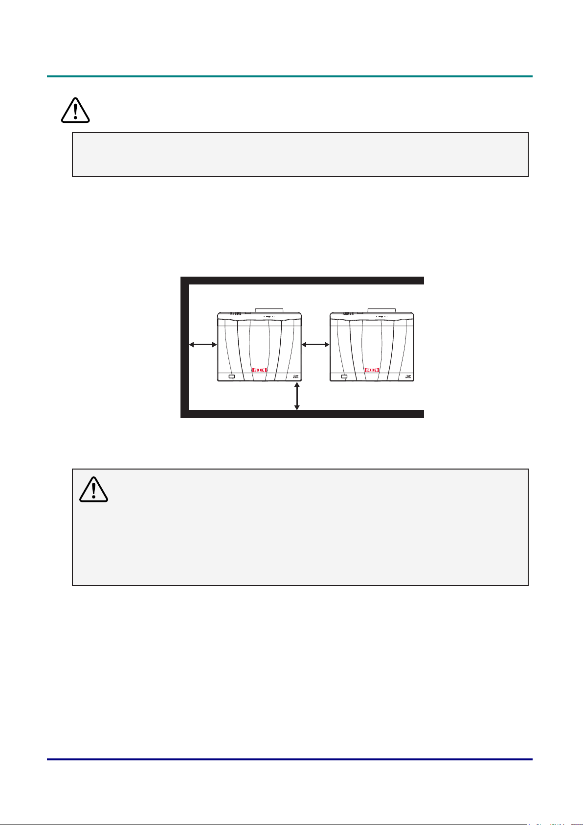
• Leave an appropriate space from the sides and back of the shell in order to ventilate and cool down the
projector. To ensure proper ventilation for your projector, avoid placing the projector in a conned space
and make sure to allow at least 30 cm clearance around the vents as shown in the illustration below.
300mm
(12”)
300mm
(12”)
(12”)
300mm
• Do not cover the vent of the projector. Poor radiation may shorten the service life or even cause
dangers.
• Remove the AC power plug if the projector is not to be used for a long time.
Caution:
• Do not set the projector in greasy, wet, or smoky conditions such as in a kitchen, to prevent a
malfunction or accident. If the projector comes in contact with oil or chemicals, it may become
deteriorated.
• Read and keep this manual for future reference.
• The mains plug/appliance coupler is used as disconnect device, the disconnect device shall remain
readily operable.
— v —
Page 7

DLP Projector — Owner’s Manual
Safety Guide
• All the safety and operating instructions should be read before the product is operated.
• Read all of the instructions given here and retain them for later use. Unplug this projector from AC
power supply before cleaning. Do not use liquid or aerosol cleaners.
• Use a damp cloth for cleaning.
• Follow all warnings and instructions marked on the projector.
• For added protection to the projector during a lightning storm, or when it is left unattended and unused
for long periods of time, unplug it from the wall outlet. This will prevent damage due to lightning and
power line surges.
• Do not expose this unit to rain or use near water... for example, in a wet basement, near a swimming
pool, etc...
• Do not use attachments not recommended by the manufacturer as they may cause hazards.
• Do not place this projector on an unstable cart, stand, or table. The projector may fall, causing
serious injury to a child or an adult, and serious damage to the projector.
• Use only with a cart or stand recommended by the manufacturer, or sold with the projector.
Wall or shelf mounting should follow the manufacturer’s instructions, and should use a mounting kit
approved by the manufacturers.
• An appliance and cart combination should be moved with care. Quick stops, excessive force, and
uneven surfaces may cause the appliance and cart combination to overturn.
• Slots and openings in the back and bottom of the cabinet are provided for ventilation, to ensure reliable
operation of the equipment and to protect it from overheating.
• The openings should never be covered with cloth or other materials, and the bottom opening should not
be blocked by placing the projector on a bed, sofa, rug, or other similar surface. This projector should
never be placed near or over a radiator or heat register.
• This projector should not be placed in a build-in installation such as a book case unless proper
ventilation is provided.
• Never push objects of any kind into this projector through cabinet slots as they may touch dangerous
voltage points or short out parts that could result in a re or electric shock. Never spill liquid of any kind
on the projector.
• Do not install the projector near the ventilation duct of air-conditioning equipment.
• This projector should be operated only from the type of power source indicated on the marking label.
• If you are not sure of the type of power supplied, consult your authorized dealer or local power
company.
• Do not overload wall outlets and extension cords as this can result in re or electric shock. Do not allow
anything to rest on the power cord. Do not locate this projector where the cord may be damaged by
persons walking on it.
• Do not attempt to service this projector yourself as opening or removing the covers may expose you to
dangerous voltage or other hazards. Refer all servicing to qualied service personnel.
• Unplug this projector from wall outlet and refer servicing to qualied service personnel under the
following conditions:
¾ When the power cord or plug is damaged or frayed.
¾ If liquid has been spilled into the projector.
¾ If the projector has been exposed to rain or water.
¾ If the projector does not operate normally by following the operating instructions. Adjust only those
controls that are covered by the operating instructions as improper adjustment of other controls
may result in damage and will often require extensive work by a qualied technician to restore the
projector to normal operation.
¾ If the projector has been dropped or the cabinet has been damaged.
— vi —
Page 8
Preface
¾ When the projector exhibits a distinct change in performance - this indicates a need for service.
• When replacement parts are required, be sure the service technician has used replacement parts
specied by the manufacturer that have the same characteristics as the original part. Unauthorized
substitutions may result in re, electric shock, or injury to persons.
• Upon completion of any service or repairs to this projector, ask the service technician to perform routine
safety checks to determine that the projector is in safe operating condition.
Information for users in the European Union
This is a device to project images onto a screen, etc., and is not intended for use as indoor lighting in a
domestic environment. Directive 2009/125/EC.
Note for customers in the US
Lamp(s) inside this product contain mercury and must be recycled or disposed of according to
local state or federal laws.
Lamp(s) inside this product contain mercury and must be recycled or disposed of according to local state
or federal laws.
Air circulation
Vents in the cabinet are provided for ventilation. To ensure reliable operation of the product and to protect
it from overheating, these openings must not be blocked or covered.
Caution:
• Hot air is exhausted from the exhaust vent. When using or installing the projector, the following
precautions should be taken.
• Donotputanyammableobjects,orspraycanneartheprojector.Hotairisexhaustedfromtheair
vents.
• Keep the exhaust vent at least 1m away from any objects.
• Do not touch a peripheral part of the exhaust vent, especially screws and metallic part. This area
will become hot while the projector is being used.
• Do not put anything on the projector. Objects put on the cabinet will not only get damaged but also
maycauserehazardbyheat.
• Cooling fans are provided to cool down the projector.
• The fan’s running speed is changed according to the temperature inside the projector.
Caution:
Contains mercury
• For more information on safe handling procedures, the measures to be taken in case of accidental
breakage and safe disposal options visit: ec.gc.ca/mercure-mercury/.
• Dispose of or recycle in accordance with applicable laws.
— vii —
Page 9
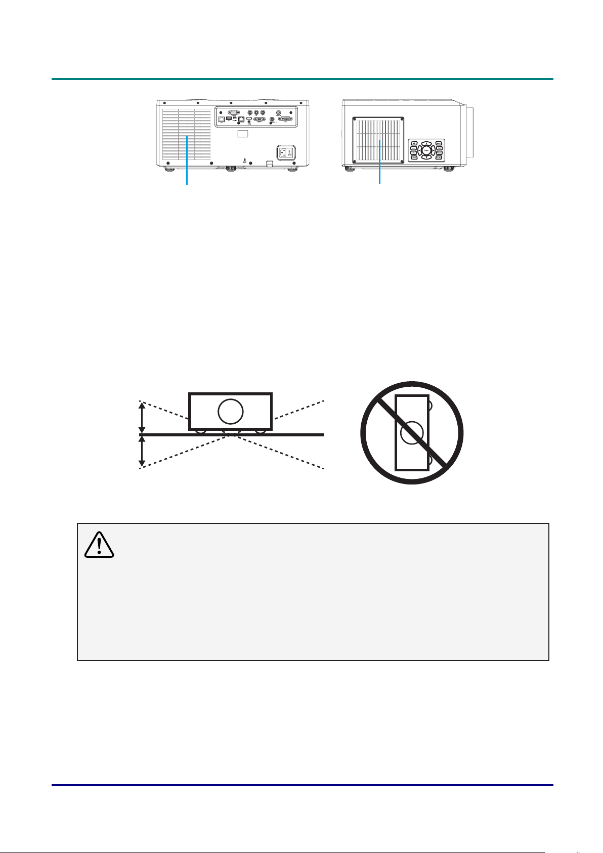
DLP Projector — Owner’s Manual
20
20
Air Intake VentExhaust Vent
Moving the projector
When moving the projector, take care of the lens and retract the adjustable foot to prevent damage to the
lens and cabinet.
Installing the projector properly
• Please set the projector on nearly-level.
• Be sure to install the projector properly. Improper installation may reduce the lamp lifetime and even
cause a re hazard.
• Do not roll the projector more than 20° from side to side.
• Do not put the projector on either side to project an image.
°
°
Caution in ceiling installation the projector
• Onlyqualiedpersonalisauthorizedforceilinginstallation.
• We are not responsible for the hurt and damage caused by ceiling bracket that purchased from
unauthorized dealer even in warranty period.
• Remove the ceiling bracket immediately while not use.
• While installing, torque screwdriver is suggested, don’t use electric or impact-type screwdriver.
• Please read the manual of bracket for details.
• The bracket is subject to change without notice.
— viii —
Page 10
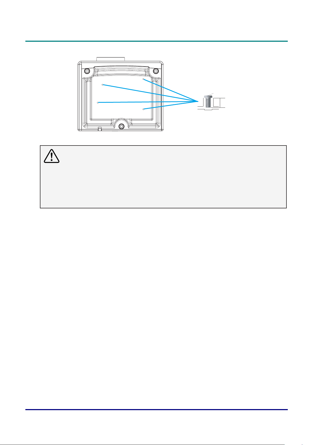
Preface
M6 x 4
10mm
Caution in moving or transporting the projector
• Do not drop or bump the projector, otherwise damages or malfunctions may result.
• When carrying the projector, use a suitable carrying case.
• Do not transport the projector by courier or any other transport service in an unsuitable transport
case. This may cause damage to the projector. For information about transporting the projector by
courier or any other transport service, consult your dealer.
• Do not put the projector in a case before it is cooled enough.
— ix —
Page 11

DLP Projector — Owner’s Manual
Compliance
FCC Caution
Note: This equipment has been tested and found to comply with the limits for a Class A digital device,
pursuant to Part 15 of the FCC Rules. These limits are designed to provide reasonable protection against
harmful interference in a residential installation. This equipment generates, uses, and can radiate radio
frequency energy, and if not installed and used in accordance with the instructions, may cause harmful
interference to radio communications. However, there is no guarantee that interference will not occur in a
particular installation. If this equipment does cause harmful interference to radio or television reception,
which can be determined by turning the equipment off and on, the user is encouraged to try to correct the
interference by one or more of the following measures:
• Reorient or relocate the receiving antenna.
• Increase the separation between the equipment and receiver.
• Connect the equipment into an outlet on a circuit different from that to which the receiver is connected.
• Consult the dealer or an experienced radio/TV technician for help.
Use of shielded cable is required to comply with class A limits in Subpart B of Part 15 of FCC Rules.
Do not make any changes or modications to the equipment unless otherwise specied in the instructions.
If such changes or modications should be made, you could be required to stop operation of the
equipment.
Model Number : EK-610U/EK611W/EK-612X
EK-610UA/EK-611WA/EK-612XA
Trade Name : EIKI
Responsible party : EIKI International, Inc.
Address : 30251 Esperanza Rancho Santa Margarita CA 92688-2132
Telephone No. : 800-242-3454 (949-457-0200)
AC Power Cord Requirement
The AC Power Cord supplied with this projector meets the requirement for use in the country you
purchased it.
AC Power Cord for the United States and Canada:
AC Power Cord used in the United States and Canada is listed by the Underwriters Laboratories (UL) and
certied by the Canadian Standard Association (CSA).
AC Power Cord has a grounding-type AC line plug. This is a safety feature to be sure that the plug will t
into the power outlet. Do not try to defeat this safety feature. Should you be unable to insert the plug into
the outlet, contact your electrician.
— x —
Page 12

Preface
Warning:
Aplugwithbaredexiblecordishazardousifengagedinalivesocketoutlet.
The Wires in this mains lead are coloured in accordance with the following code:
• Green-and-yellow ......... Earth
• Blue .............................. Neutral
• Brown ........................... Live
As the colours of the wires in the mains lead of this apparatus may not correspond with the coloured
markings identifying the terminals in your plug proceed as follows:
• The wire which is coloured green-and-yellow must be connected to the terminal in the plug which is
marked by the letter E or by the safety earth symbol or coloured green or green-and-yellow.
• The wire which is coloured blue must be connected to the terminal which is marked with the letter N or
coloured black.
• The wire which is coloured brown must be connected to the terminal which is marked with the letter L or
coloured red.
Warning:
This apparatus must be earthed.
Note:
The socket-outlet should be installed near the equipment and easily accessible.
— xi —
Page 13

DLP Projector — Owner’s Manual
Contents
GETTING STARTED ................................................................................................................ 1
Packing checklist ...................................................................................................................... 1
Views of Projector Parts ......................................................................................................... 2
Front-right View .....................................................................................................................................2
Left View ................................................................................................................................................3
Rear View ..............................................................................................................................................4
Built-in Keypad .......................................................................................................................................5
Bottom View ...........................................................................................................................................6
remote control Parts ............................................................................................................. 7
remote control oPerating range ........................................................................................... 9
Projector and remote control Buttons .................................................................................. 9
inserting the remote control Batteries .................................................................................. 9
SETUP AND OPERATION .................................................................................................... 10
installing the Projection lens ................................................................................................. 10
starting and shutting down the Projector ............................................................................. 12
Turn the Projector On ..........................................................................................................................12
Turn the Projector Off ..........................................................................................................................12
adjusting the Projector leVel ................................................................................................ 13
adjusting the Zoom, focus, and keystone ............................................................................... 14
adjusting the Projecting image’s Position ............................................................................... 15
Projection Lens ....................................................................................................................................15
Optional Lenses and Projection Size ...................................................................................................18
other oPtional Parts ............................................................................................................. 20
ON-SCREEN DISPLAY (OSD) MENU SETTINGS ............................................................... 21
osd menu controls ............................................................................................................... 21
Navigating the OSD .............................................................................................................................21
setting the osd language ..................................................................................................... 22
osd menu oVerView ............................................................................................................... 23
Picture menu .......................................................................................................................... 29
3D Display Menu .................................................................................................................................30
HSG Adjustment Menu ........................................................................................................................31
Advanced Menu ...................................................................................................................................32
outPut menu ........................................................................................................................... 33
Image Warping Menu...........................................................................................................................34
PIP/PBP Menu .....................................................................................................................................35
— xii —
Page 14

Preface
setuP menu ............................................................................................................................. 37
Lens Function Menu ............................................................................................................................38
Menu Preferences Menu .....................................................................................................................39
Pin Menu ..............................................................................................................................................40
Communications Menu ........................................................................................................................41
oPtion menu ............................................................................................................................ 42
Power Settings Menu ...........................................................................................................................43
Light Source Settings Menu .................................................................................................................44
control your Projector using weB Browser ........................................................................ 45
Wired LAN Terminal functionalities ......................................................................................................45
Supported External Devices ................................................................................................................45
LAN_RJ45 ...........................................................................................................................................46
RS232 by Telnet Function ....................................................................................................................50
MAINTENANCE AND SECURITY ........................................................................................ 53
rePlacing the Projection lamP ................................................................................................ 53
Resetting the Lamp ..............................................................................................................................55
rePlacing the Projection lens ................................................................................................ 56
rePlacing the filter ................................................................................................................ 58
cleaning the Projector ........................................................................................................... 59
Cleaning the Lens ................................................................................................................................59
Cleaning the Case ...............................................................................................................................59
using the kensington® lock .................................................................................................... 60
TROUBLESHOOTING .......................................................................................................... 61
common ProBlems and solutions ............................................................................................. 61
tiPs for trouBleshooting ........................................................................................................ 61
led error messages .............................................................................................................. 62
image ProBlems ....................................................................................................................... 63
lamP ProBlems ........................................................................................................................ 63
remote control ProBlems ...................................................................................................... 64
haVing the Projector serViced ............................................................................................... 64
hdmi Q & a ............................................................................................................................ 65
SPECIFICATIONS ................................................................................................................. 66
sPecifications .......................................................................................................................... 66
Projection distance Vs. Projection siZe .................................................................................. 67
Projection Distance and Size Table .....................................................................................................67
timing mode taBle ................................................................................................................... 70
Projector dimensions .............................................................................................................. 72
— xiii —
Page 15

DLP Projector — Owner’s Manual
REGULATORY COMPLIANCE ............................................................................................. 73
fcc warning .......................................................................................................................... 73
caution ................................................................................................................................... 73
canada .................................................................................................................................... 73
safety certifications .............................................................................................................. 73
— xiv —
Page 16
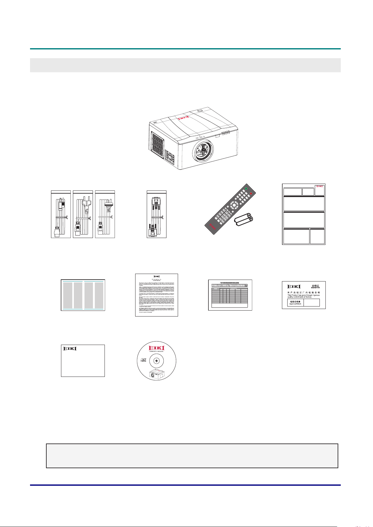
Packing Checklist
Carefully unpack the projector and check that the following items are included:
DLP PROJECTOR
Gamma
Lens H
Lens V
Keystone H
Keystone V
Shutter
(AV Mute)
Zoom
Hot Key
Pattern
DLP Projector — Owner’s Manual
GettinG Started
ON
1
OFF
4
2
7
5
3
Info
8
6
Auto
0
9
Mode
Source
Enter
Menu
Bright
Cont.
Exit
PIP
-
Focus
-
+
+
Quick Start Guide
Accessories List
How to install lens
Turn on the projector Turn off the projector
EK-610
POWER CORD
US Type*1 / Euro Type*1 /
China Type*1 for China
Safety Guide Safety Guide
1
2
SAFETY GUIDE WARRANTY CARD
WARRANTY CARD
for China
VGA CABLE REMOTE CONTROL
(WITH TWO AAA
ὅ㌖⚥㓧⹄搰⮡“䓝⫸ᾉ〗ṏ⑩㰉㝻㍏⇞䭉瀲≆㱽炱㍏⇞ⅷ⮹䓝⫸ᾉ〗ṏ ⑩⹇⺫⎶⮡䍗⠫忈ㆸ䘬㰉㝻炻Ὣ徃
䓇ṏ撨ⓖỶ㰉㝻䓝⫸ᾉ〗ṏ⑩炻ᾅ㉌䍗⠫Ṣỻ炻ṭ㍸ὃ㚱ℛ㛔ṏ⑩⎗傥⏓㚱㚱㭺⍲㚱⭛䈑 峐⤪⎶烉
悐ẞ⎵䦘
ݹᵪᕅ(
ᕩ⡷(ᘛࡺ⼧䬌)
⚟⌑ⴆ؍ᣔᔰޣ
㔶㓯,㓯ᶀ
⭥Ⓚ㓯
⭥Ⓚᨂᓗ㓴Ԧ
䠁Ԧ(ᘛࡺ⼧䬌,䬌䪹ㅹ)
䚕᧗ಘ
˕烉堐䣢宍㚱㭺㚱⭛䈑峐⛐宍悐ẞ㚱⛯峐㛸瀌䘬⏓濌⛯⛐SJ/T11363-2006㞯Ⅾ奬⭂䘬旸濌天㯪ẍᶳˤ
ʹ烉堐䣢宍㚱㭺㚱⭛䈑峐军⮹⛐宍悐ẞ䘬㝸ᶨ⛯峐㛸瀌䘬⏓濌崭↢SJ/T11363-2006㞯Ⅾ奬⭂䘬旸濌天㯪ˤ
⢯㲐烉戜Ḷ㫏䚇ᶶ⚥⮡ḶRoHS䘬澵⎴奬⭂炻㛔㈽⼙㛢ṏ⑩䫎⎰㫏䚇RoHS㊯濶(䓝㮼ˣ䓝⫸学⢯旸⇞ἧ䓐㝸ṃ㚱⭛䈑峐㊯濶),㛔
堐㞯㚱"X"䘬㚱悐ẞ⛯㫏䚇ROHS㊯濶孠瀃⢾䘬悐ẞˤ
for USA
EK-610
CD-ROM
(THIS OWNER’S MANUAL)
BATTERIES)
ṏ⑩㚱㭺㚱⭛䈑峐ㆾ䳈䘬⎵䦘⍲⏓濌濪堐
㚱㭺㚱⭛䈑峐ㆾ䳈
摭炷Pb˅ 㰆炷Hg˅ 擱炷Cd˅ 瀟ẟ撔炷Cr(VI)˅ ⣂㹜俼劗炷PBB˅ ⣂㹜Ḵ劗慂炷PBDE˅
XOOO OO
䬍ᡆ䬍䭱䠁)
XOOO OO
䮌ཤ
XXOO OO
⚟⌑
XOOO OO
⛩⚟ಘ
XOOO OO
XOOO OO
仾ᡷ㓴Ԧ
OOXO OO
OOXO OO
ᓖᔰޣ
XOOO OO
สᶯ㓴Ԧ
XOOO OO
XOOO OO
XOOO OO
XOOO OO
XOOO OO
RoHS CARD
for China
QUICK START GUIDE
QC PASS CARD
for China
for China
Contact your dealer immediately if any items are missing, appear damaged, or if the unit does not work. It
is recommend that you keep the original packing material should you ever need to return the equipment
for warranty service.
Note:
• Avoid using the projector in dusty environments.
— 1 —
Page 17
DLP Projector — Owner’s Manual
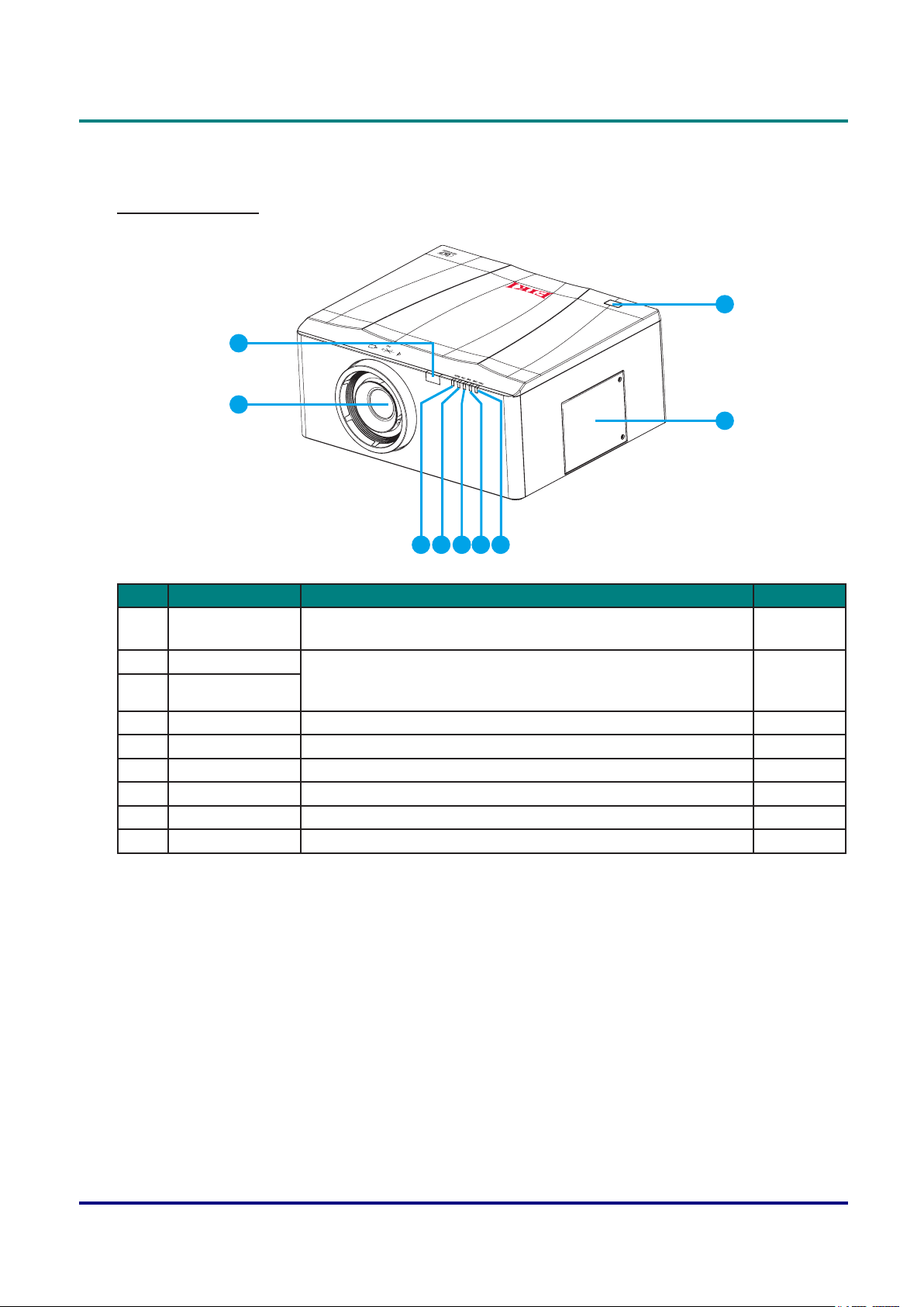
Views of Projector Parts
Front-right View
2
1
3
4
56789
Item LabeL DescrIptIon see page
1 Projection Lens Allows automated lens control and adjustment: vertical and
11
horizontal offsets, zoom and focus.
2 Front IR Sensor Receives signals from the IR remote. Keep the signal path to
3 Top IR Sensor
the sensor unobstructed for uninterrupted communication with
9
the projector.
4 Lamp Door Use the lamp door to access the lamp module. 53
5 Power LED Indicate the power status. 62
6 Lamp LED Indicate the lamp status. 62
7 Temp LED Indicate the temperature status. 62
8 Filter LED Indicate the lter status. 62
9 Shutter LED Indicate the shutter status. -
— 2 —
Page 18
DLP Projector — Owner’s Manual
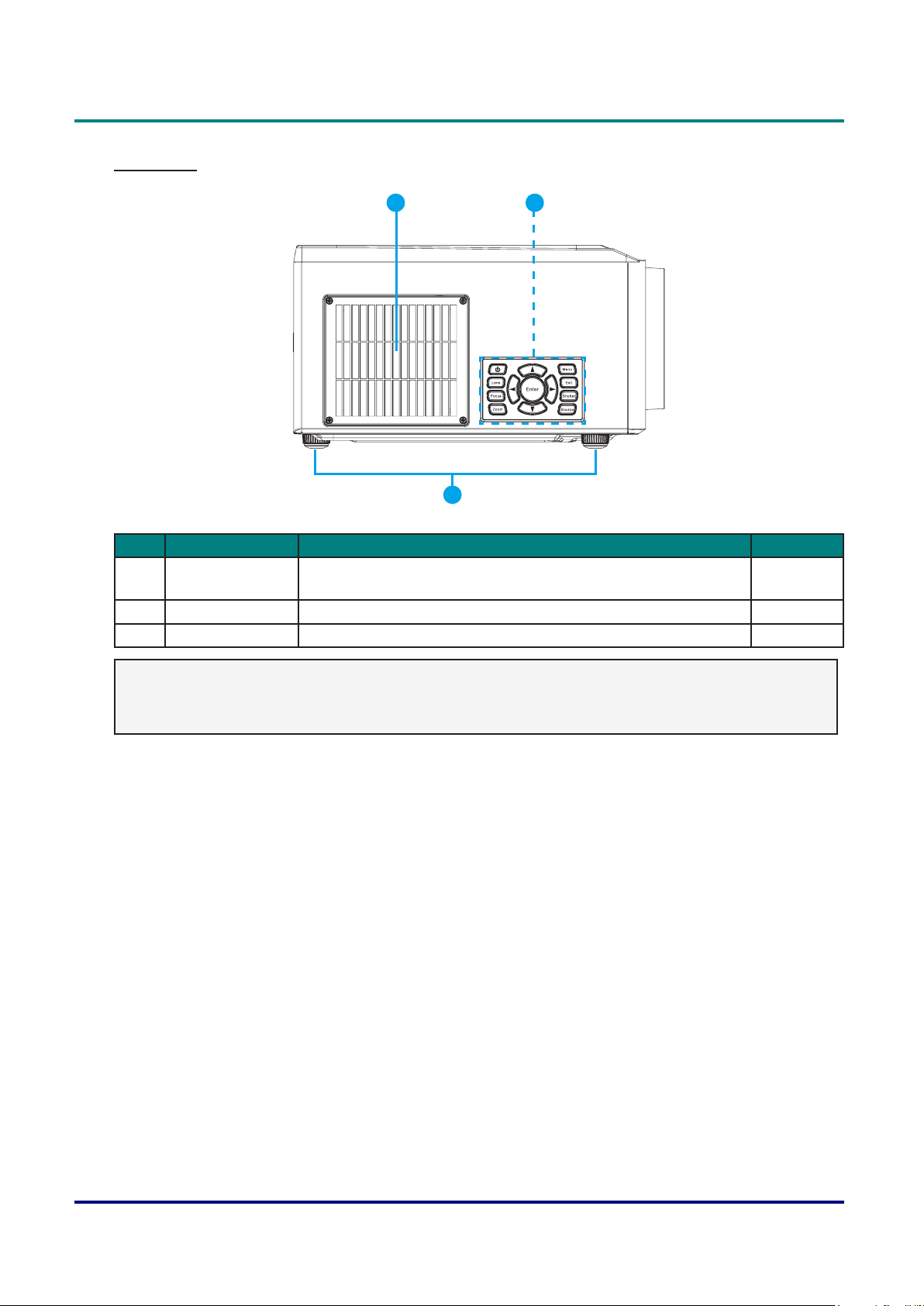
Left View
1 2
3
Item LabeL DescrIptIon see page
1 Cooling Air Vents
(Intake)
2 Built-in Keypad Control the projector. 5
3 Adjustable Feet Raise or lower the feet to level the projector. 14
Keep these vents unobstructed to prevent the projector from
overheating.
-
Important:
Ventilation openings on the projector allow for good air circulation, which keeps the projector lamp
cool. Do not obstruct any of the ventilation openings.
— 3 —
Page 19
DLP Projector — Owner’s Manual
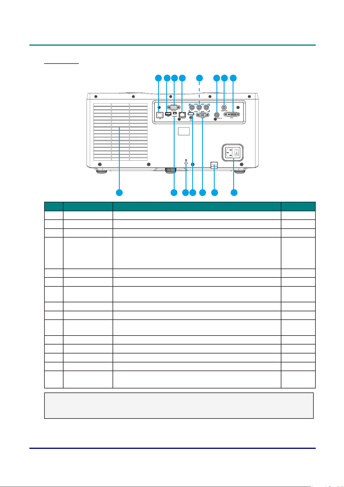
Rear View
1 2 3 4 5 6 87
15
913 11 1014 12
Item LabeL DescrIptIon see page
1 LAN Connect a LAN cable from Ethernet. 46
2 USB Connect the WIFI dongle. -
3 RS-232C Connect RS-232 serial port cable for remote control. 51
4 HDBaseT Connect a RJ45 Cat5/Cat6 Ethernet cable to input
-
uncompressed high-denition video signals.
Only supports Full-HD video format over network cable. Audio
format, Control, Ethernet and Power supply are not supported.
5 Component Connect to YPbPr output signal with RCA type input terminal. -
6 Video IN Connect the COMPOSITE cable from a video device. -
7 Remote IN Connect to the remote control wired terminal for serial control
-
projector.
8 DVI-D Connect to DVI source. -
9 AC Input Connect to the supplied power adapter. 13
10 Security Bar For extended security, attach an anti-theft chain or wire to the
-
security bar on the projector.
11 VGA IN Connect the VGA cable from a computer or component device. -
12 HDMI Connect the HDMI cable from a HDMI device. -
13 Kensington Lock Use to secure the projector to countertops, tables, etc. 60
14 Service Service only. -
15 Cooling Air Vents
(Exhaust)
Keep these vents unobstructed to prevent the projector from
overheating.
-
Note:
• To use this feature, you must plug in the connector before turn on/off the projector.
• Do not use this jack for anything other than intended use.
— 4 —
Page 20
DLP Projector — Owner’s Manual
Warning:
As a safety precaution, disconnect all power to the projector and connecting devices before making
connections.
Important:
Ventilation openings on the projector allow for good air circulation, which keeps the projector lamp
cool. Do not obstruct any of the ventilation openings.
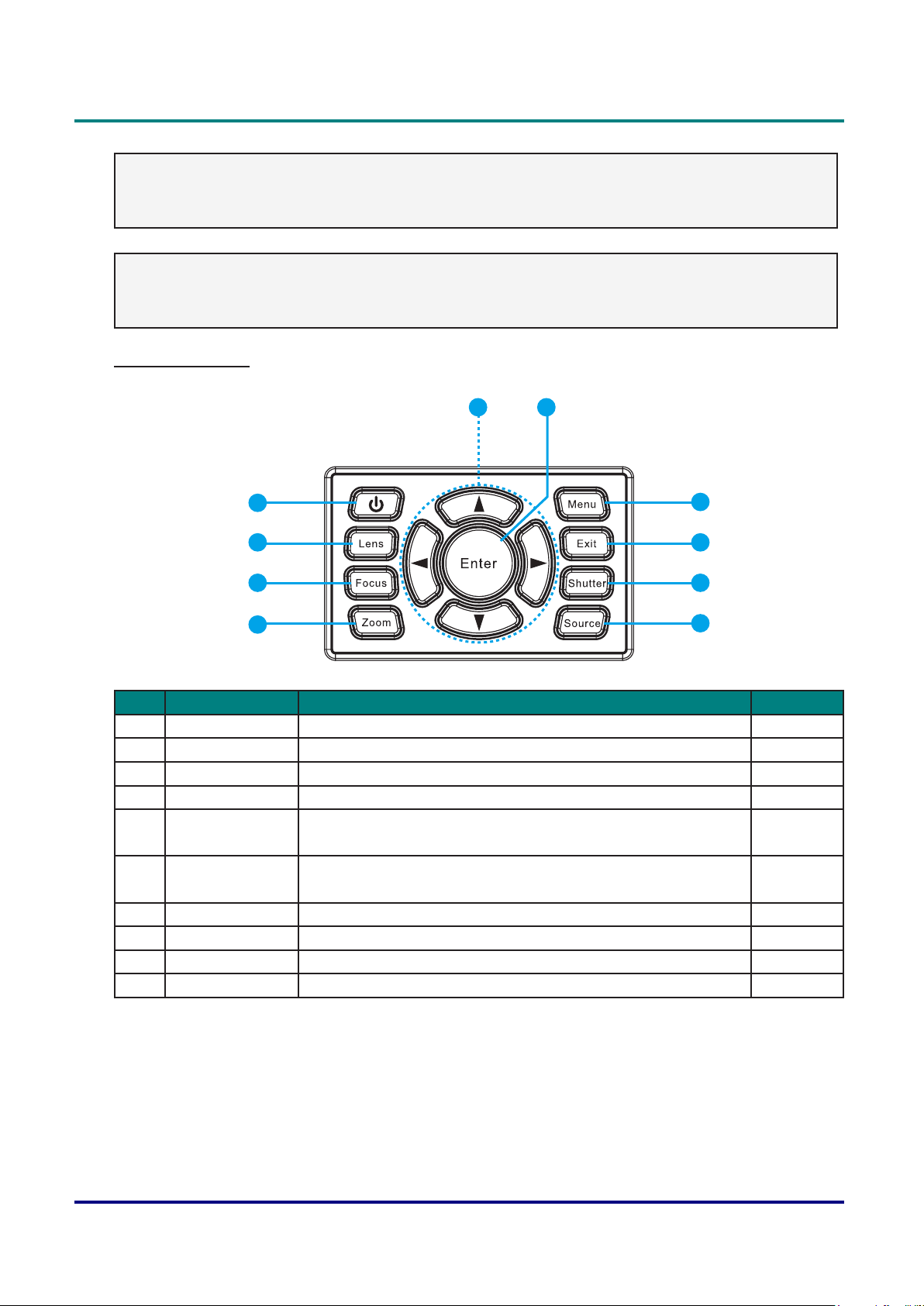
Built-in Keypad
5 6
4
3
2
1
7
8
9
10
Item LabeL DescrIptIon see page
1 Zoom Adjust zoom. 15
2 Focus Adjust focus. 15
3 Lens Adjust the lens vertical or horizontal offset setting. 16-18
4 Power Turn the projector on or off. 13
5 Arrow keys • Adjust a setting UP or DOWN.
-
• Navigate within a menu.
6 Enter • Select a highlighted menu item.
22
• Change or accept a value.
7 Menu Display menus. 22
8 Exit Return to previous level or exit menus if at top level. 22
9 Shutter Display or blank the video image. -
10 Source Select an input for the main or PIP/PBP image. 36
— 5 —
Page 21

DLP Projector — Owner’s Manual
95mm 125.4mm
Bottom View
1 1
216.2mm130.8mm
2
2
241.2mm105.8mm
1
160mm95.4mm
2
2
Item LabeL DescrIptIon see page
1 Adjustable Feet Raise or lower the feet to level the projector. 14
2 Ceiling support
holes
Contact your dealer for information on mounting the projector on
a ceiling.
viii-ix
Note:
• When installing, ensure that you use only UL Listed ceiling mounts.
• For ceiling installations, use approved mounting hardware and M6 x 4 screws with a maximum
screw depth of 10 mm (0.39 inch).
• The construction of the ceiling mount must be of a suitable shape and strength. The ceiling mount
load capacity must exceed the weight of the installed equipment, and as an additional precaution
be capable of withstanding three times the weight of the equipment (not less than 71.4 kg) over a
period of 60 seconds.
— 6 —
Page 22
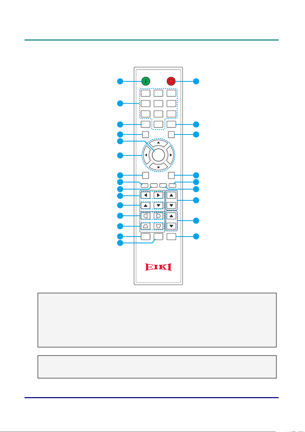
Remote Control Parts
DLP Projector — Owner’s Manual
ON OFF
1
21 3
16
10
11
12
13
14
15
2
54 6
87 9
3
4
Info
Auto
Mode
0
Source
17
18
5
6
7
8
9
Enter
Menu Exit
Gamma Bright Cont. PIP
Hot Key
Focus
Zoom
Pattern
Keystone H
Keystone V
Shutter
(AV Mute)
Lens H
Lens V
19
20
21
22
23
24
Important:
1.Avoidusingtheprojectorwithbrightuorescentlightingturnedon.Certainhigh-frequency
uorescentlightscandisruptremotecontroloperation.
2. Be sure nothing obstructs the path between the remote control and the projector. If the path
between the remote control and the projector is obstructed, you can bounce the signal off certain
reectivesurfacessuchasprojectorscreens.
3. The buttons and keys on the projector have the same functions as the corresponding buttons on the
remote control. This owner’s manual describes the functions based on the remote control.
Note:
Complies with FDA performance standards for laser products except for deviations pursuant to
Laser Notice No. 50, dated June 24, 2007.
— 7 —
Page 23
DLP Projector — Owner’s Manual
Item LabeL DescrIptIon see page
1 Power on Turn projector ON. 13
2 Number Keys Enter a number (such as PIN code) or source hotkey.
Source Hotkey Key:
1: VGA
2: HDMI
3: Component
4: HDBaseT
5: Video
6: DVI-D
3 Info Display source image information. -
4 Auto Automatically optimize image. -
5 Enter • Select a highlighted menu item.
• Change or accept a value.
6 Arrow Keys • Adjust a setting UP or DOWN.
• Navigate within a menu.
7 Menu Display menus. 22
8 Gamma Adjust mid-range levels. -
9 Bright Adjust amount of light in the image. -
10 Lens H Adjust the position of the image horizontally. -
11 Lens V Adjust the position of the image vertically. -
12 Keystone H Adjust the horizontal keystone. 15
13 Keystone V Adjust the vertical keystone. 15
14 Shutter
(AV Mute)
15 Hot Key Select your preset keys quickly. 43
16 OFF Turn projector OFF. 13
17 Mode Select the preset display mode. -
18 Source Select an input for the main or PIP/PBP image. 36
19 Exit Return to previous level or exit menus if at top level. 22
20 PIP Turn PIP/PBP ON/OFF. 36
21 Cont. Adjust difference between dark and light. -
22 Focus Adjust focus to improve image clarity as desired. 15
23 Zoom Adjust zoom to achieve a desired image size. 15
24 Pattern Display a test pattern. -
Display or blank the video image. -
-
22
22
Caution:
Useofcontrols,adjustmentsorperformanceofproceduresotherthanthosespeciedhereinmay
result in hazardous laser light exposure.
— 8 —
Page 24
DLP Projector — Owner’s Manual
Remote Control Operating Range
The remote control uses infrared transmission to control the projector. It is not necessary to point the
remote directly at the projector. Provided you are not holding the remote perpendicular to the sides or
the rear of the projector, the remote will function well within a radius of about 7 meters (23 feet) and 15
degrees above or below the projector level. If the projector does not respond to the remote control, move
a little closer.
Projector and Remote Control Buttons
The projector can be operated using the remote control or the buttons on the top of the projector. All
operations can be carried out with the remote control; however, the buttons on the projector are limited in
use.
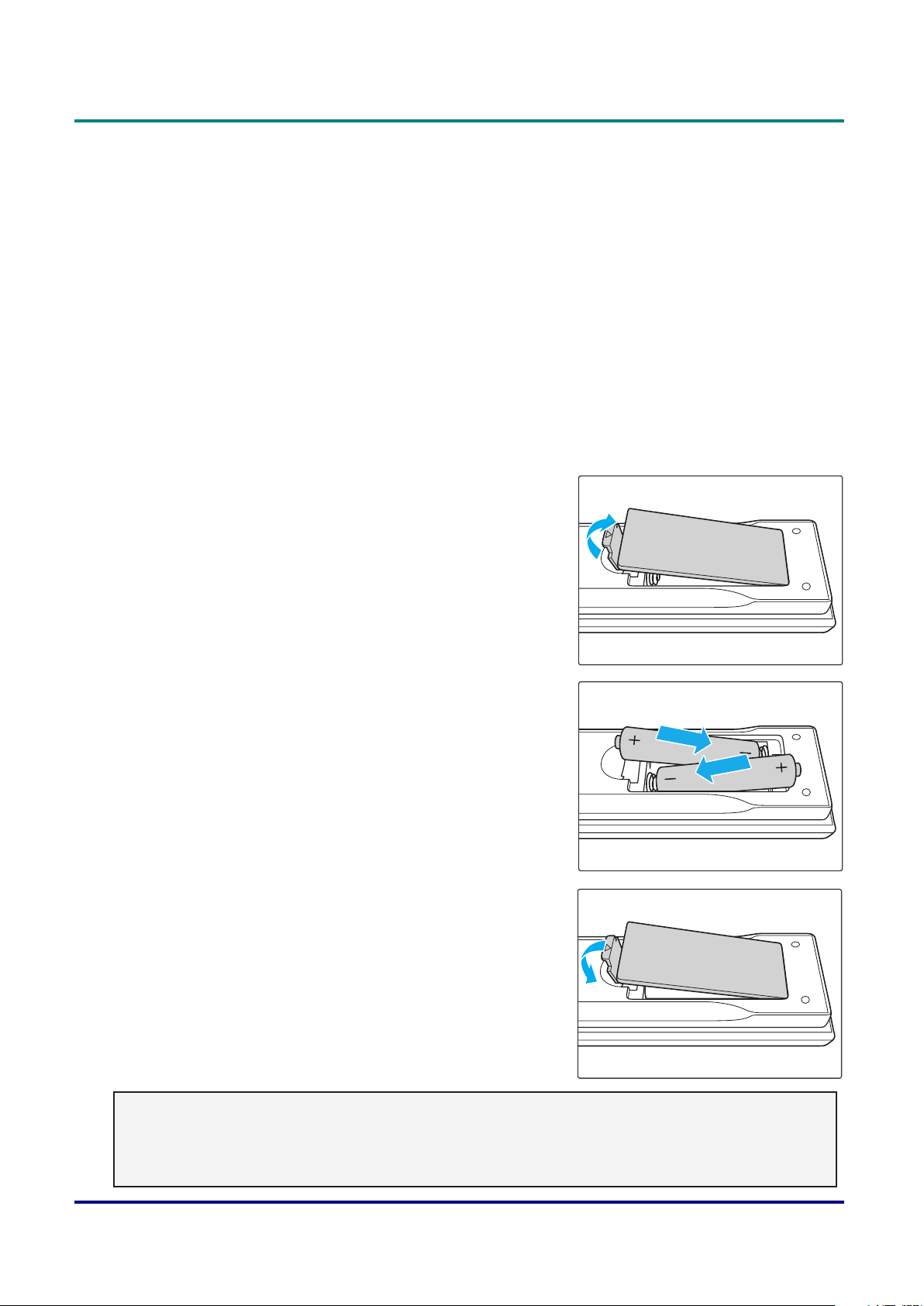
Inserting the Remote Control Batteries
1. Remove the battery compartment cover as shown in the
illustration.
2. Insert the batteries with correct polarity (+/-) as shown inside
the battery compartment.
3. Replace the cover.
Caution:
• Only use AAA batteries (Alkaline batteries are recommended).
• Dispose of used batteries according to local ordinance regulations.
• Remove the batteries when not using the projector for prolonged periods.
— 9 —
Page 25

DLP Projector — Owner’s Manual
Remote Control Code
The ten different remote control codes (Code 0 - Code 9) are assigned to this projector. Switching the
remote control codes prevents interference from other remote controls when several projectors or video
equipment next to each other are being operated at the same time. Change the remote control code for
the projector rst before changing that for the remote control. See “Projector ID” in the Communications
Menu on page 42.
To change the code for the Remote Control:
Press and hold the Mode button and a number button (0-9) on the remote control for more than three
seconds to switch among the codes.
Default setting : 0
To change the Projector ID for the projector:
Select a Projector Address in this Setting Menu. (SETUP -> Communications -> Projector ID)
— 10 —
Page 26
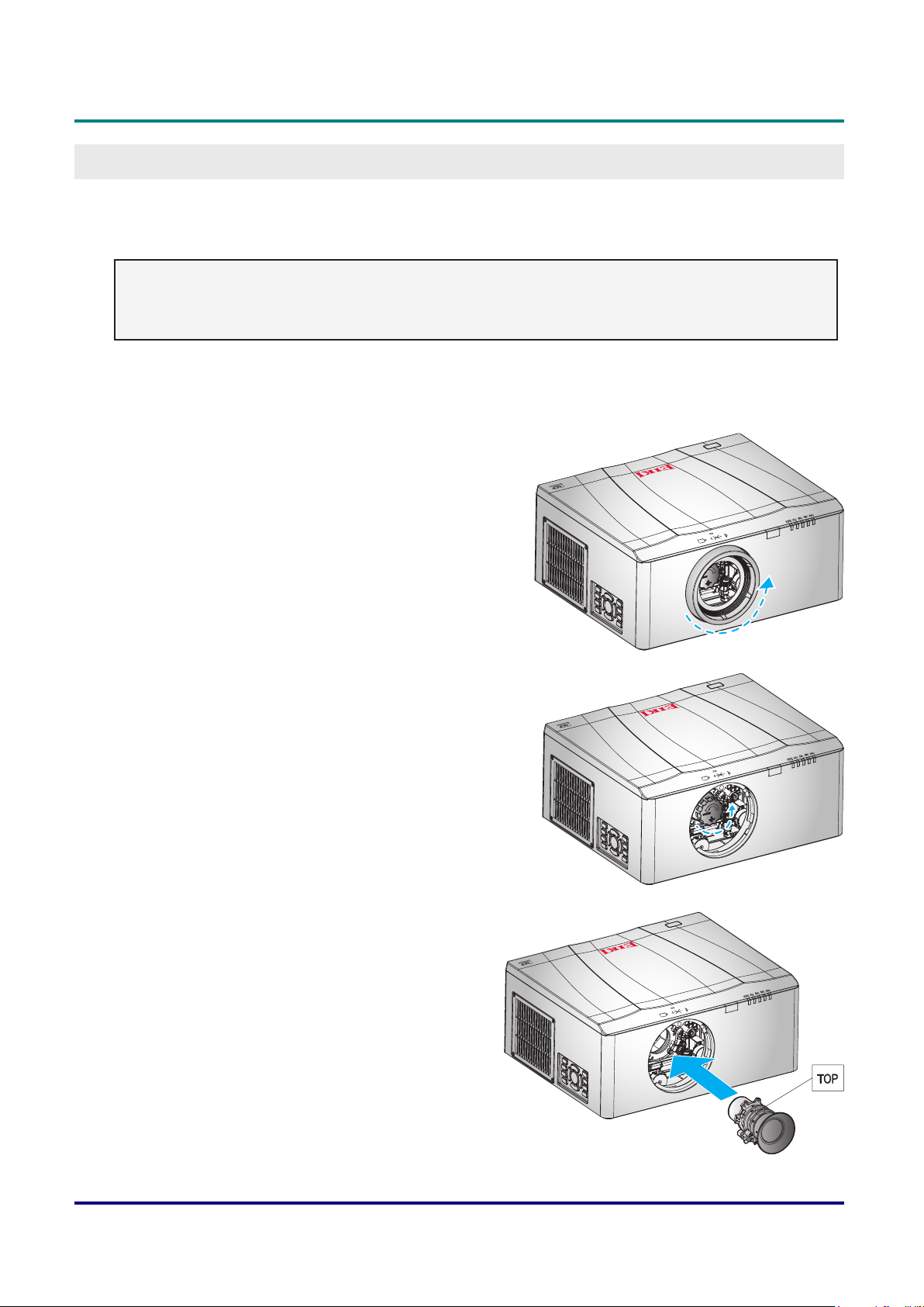
Installing the Projection Lens
Before setting up the projector, install the projection lens on the projector.
Important:
• Before installation, check where the projector is used and prepare a suitable lens.
• For details, contact the sales dealer where you purchased the projector.
1. Turn the projector off. Allow the projector to cool down into standby mode.
2. Rotate the lens ring counter-clockwise and then
remove it from the projector.
DLP Projector — Owner’s Manual
Setup and OperatiOn
3. Rotate the lens cover counter-clockwise and then
remove it from the projector.
4. With the label “TOP” on the lens assembly facing up,
install the assembly into the lens mount.
— 11 —
Page 27
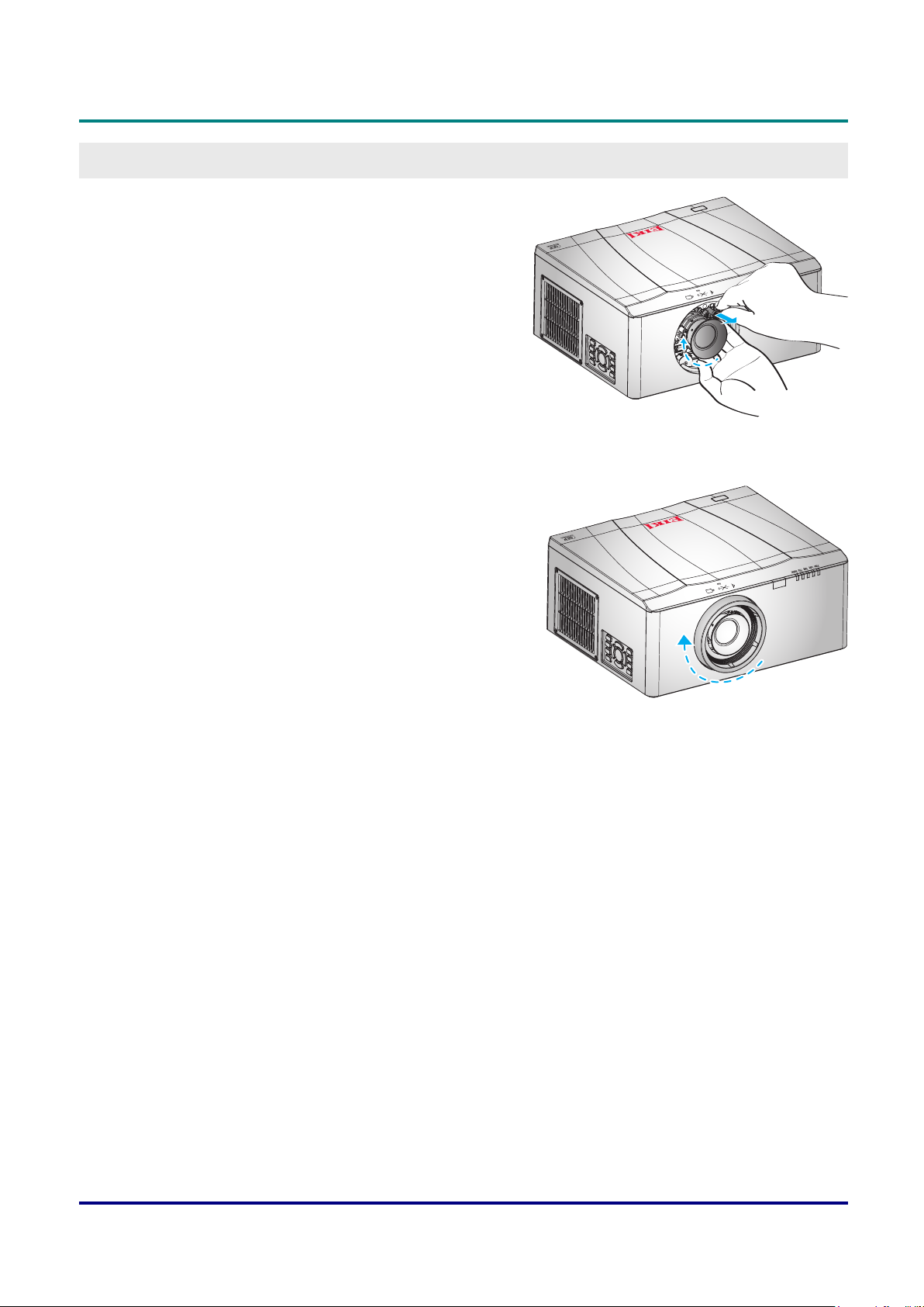
DLP Projector — Owner’s Manual
5. While pulling the rejection pin, rotate the lens clockwise
to lock the lens in place. Then release the rejection pin.
6. Replace the lens ring.
— 12 —
Page 28

DLP Projector — Owner’s Manual
Starting and Shutting down the Projector
Turn the Projector On
1. Connect the power cord to the projector. Then connect the other end to a wall outlet.
The Power button on the built in keypad is illuminated.
Important:
Make sure that the Power switch is in the ON position.
2. Turn on the connected devices.
3. Turn on the projector by pressing “ ” on the remote control
or press “ ” on the built-in keypad. The Power LED is
Blue with steady light.
The projector splash screen displays and connected
devices are detected.
4. If more than one input device is connected, press the Source key on the remote control to select an
input source (VGA, HDMI, Component, HDBaseT, Composite, or DVI).
5. The projector detects the source you selected and displays the image.
Note:
Thersttimetheprojectorisused,thepreferredlanguagemaybeselectedfromthemainmenuafter
the startup screen is displayed.
Turn the Projector Off
1. Press “ ” on the built-in keypad or press “ ” on the remote control to turn off the projector. A warning
message will appear on the displayed image.
2. Press “ ” on the built-in keypad or press “ ” on the remote control again to conrm your selection. If
you do not press “ ” or “ ” again, the warning message will disappear after 3 seconds.
Caution:
• Do not unplug the power cord until all of fans are stop–indicating the projector has cooled down.
— 13 —
Page 29

DLP Projector — Owner’s Manual
Adjusting the Projector Level
Take note of the following when setting up the projector:
• The projector table or stand should be level and sturdy.
• Position the projector so that it is perpendicular to the screen.
• Ensure the cables are in a safe location. You could trip over them.
A
B
1. To raise the level of the projector, lift the projector
A
.
2. Locate the adjustable foot you wish to modify on the underside of the projector.
3. Rotate the adjustable foot clockwise to raise the projector or counter-clockwise to lower it. Repeat with
the remaining feet as necessary B.
— 14 —
Page 30

Adjusting the Zoom, Focus, and Keystone
A
1. Use the Zoom button to resize the projected
image and screen size B.
Lens H
Lens V
DLP Projector — Owner’s Manual
Focus
Hot Key
Zoom
B
Pattern
2. Use the Focus button to sharpen the
projected image A.
Keystone H
Keystone V
Shutter
(AV Mute)
3. Use the Keystone H buttons (on the remote control) to adjust the keystone
horizontally and make a squarer image. Use the Keystone V buttons (on the
remote control) to adjust keystone vertically and make a squarer image.
Keystone H
Keystone V
Shutter
(AV Mute)
Lens H
Lens V
Hot Key
Focus
Zoom
Pattern
— 15 —
Page 31

DLP Projector — Owner’s Manual
Adjusting the Projecting image’s Position
Projection Lens
The complete projection lens series as below table.
Item Lens type
Projection
Lens
A15
(AH-A22010)
A01
(AH-A22020)
A02
(AH-A22030)
A03
(AH-A21010)
A13
(AH-A23010)
Focal Length
(f)
F number 2.30-2.53 2.30-2.57 2.00-2.32 2.30-3.39 2.30-2.74
Focus spec
(MTF)
Zoom Range
(Ratio)
Zoom & Focus
Adjustment
Throw Ratio
(XGA)
Throw
Distance (XGA)
Projection
Image Size
11.11-14.06 14.03-17.96 18.07-22.59 22.56-42.87 42.60-80.90
67 lp/mm 67 lp/mm 47 lp/mm 67 lp/mm 67 lp/mm
1.26X 1.28X 1.25X 1.9X 1.9X
Motorized
0.78-0.99 0.99-1.26 1.26-1.58 1.58-3.00 3.00-5.70
0.79-6.03m 1.01~7.68m 1.28~9.63m 1.61~18.29m 3.05-34.75m
50~300”
— 16 —
Page 32

DLP Projector — Owner’s Manual
Horizontal: ±30%
Vertical: ±100%
Projection Lens: A01(AH-A22020), A03(AH-A21010), A13(AH-A23010)
Motorized Lens
Shift
(Lens shift range
based on 1/2
screen width and
height)
pLatform H V
EK-612X/
0.7”XGA
EK-611W/
0.65” WXGA
EK-610U/
0.67” WUXGA
30% 100% 0% 10%
30% 100% 30% 100%
30% 100% 30% 100%
Projection Lens: A02(AH-A22030)
pLatform H V
EK-612X/
0.7”XGA
EK-611W/
0.65” WXGA
EK-610U/
0.67” WUXGA
30% 100% 0% 10%
30% 100% 15% 70%
30% 100% 5% 50%
Projection Lens: A15(AH-A22010)
pLatform H V
EK-612X/
0.7”XGA
EK-611W/
0.65” WXGA
EK-610U/
0.67” WUXGA
30% 100% 0% 0%
30% 100% 14% 70%
30% 100% 2% 50%
rH rV
rH rV
rH rV
— 17 —
Page 33

DLP Projector — Owner’s Manual
A01(AH-A22020)/ A03(AH-A21010)/ A13(AH-A23010) lens shift range:
Motorized Lens
Shift
(Lens shift range
based on 1/2
screen width and
height)
A02(AH-A22030)/ A15(AH-A22010) lens shift range:
Lens shift range
Darker
Lens shift range
Lens shift accuracy: 0.5 pixel per step
When the lens is shifted beyond the described range of operation, the screen edges
may become darker or the images may become out of focus.
— 18 —
Page 34

DLP Projector — Owner’s Manual
Optional Lenses and Projection Size
moDeL name eK-612X/ eK-612Xa/ Xga (4:3)
DmD 0.70”
projectIon Lens
tHrow ratIo 0.78-0.99 0.99-1.26 1.26-1.58 1.58-3.00 3.00-5.70
Zoom ratIo 1.26X 1.28X 1.25X 1.9X 1.9X
tHrow DIstance 0.79-6.03m 1.01~7.68m 1.28~9.63m 1.61~18.29m 3.05~34.75m
projectIon screen sIZe projectIon DIstance (m)
tHrow ratIo 0.78 0.99 0.99 1.26 1.26 1.58 1.58 3.00 3.00 5.70
DIagonaL
(IncH)
50 0.76 1.02 0.79 1.01 1.01 1.28 1.28 1.61 1.61 3.05 3.05 5.79
60 0.91 1.22 0.95 1.21 1.21 1.54 1.54 1.93 1.93 3.66 3.66 6.95
70 1.07 1.42 1.11 1.41 1.41 1.79 1.79 2.25 2.25 4.27 4.27 8.11
80 1.22 1.63 1.27 1.61 1.61 2.05 2.05 2.57 2.57 4.88 4.88 9.27
90 1.37 1.83 1.43 1.81 1.81 2.30 2.30 2.89 2.89 5.49 5.49 10.42
100 1.52 2.03 1.58 2.01 2.01 2.56 2.56 3.21 3.21 6.10 6.10 11.58
110 1.68 2.24 1.74 2.21 2.21 2.82 2.82 3.53 3.53 6.71 6.71 12.74
120 1.83 2.44 1.90 2.41 2.41 3.07 3.07 3.85 3.85 7.32 7.32 13.90
130 1.98 2.64 2.06 2.62 2.62 3.33 3.33 4.17 4.17 7.92 7.92 15.06
140 2.13 2.84 2.22 2.82 2.82 3.58 3.58 4.49 4.49 8.53 8.53 16.22
150 2.29 3.05 2.38 3.02 3.02 3.84 3.84 4.82 4.82 9.14 9.14 17.37
160 2.44 3.25 2.54 3.22 3.22 4.10 4.10 5.14 5.14 9.75 9.75 18.53
170 2.59 3.45 2.69 3.42 3.42 4.35 4.35 5.46 5.46 10.36 10.36 19.69
180 2.74 3.66 2.85 3.62 3.62 4.61 4.61 5.78 5.78 10.97 10.97 20.85
190 2.90 3.86 3.01 3.82 3.82 4.86 4.86 6.10 6.10 11.58 11.58 22.01
200 3.05 4.06 3.17 4.02 4.02 5.12 5.12 6.42 6.42 12.19 12.19 23.16
250 3.81 5.08 3.96 5.03 5.03 6.40 6.40 8.03 8.03 15.24 15.24 28.96
300 4.57 6.10 4.75 6.03 6.04 7.68 7.68 9.63 9.63 18.29 18.29 34.75
HeIgHt
(m)
wIDtH
(m)
a15
(aH-a22010)
mIn
(m)
maX
(m)
a01
(aH-a22020)
mIn
(m)
maX
(m)
a02
(aH-a22030)
mIn
(m)
maX
(m)
a03
(aH-a21010)
mIn
(m)
maX
(m)
a13
(aH-a23010)
mIn
(m)
maX
(m)
— 19 —
Page 35

DLP Projector — Owner’s Manual
moDeL name eK-611w/ eK-611wa/ wXga (16:10)
DmD 0.65"
projectIon Lens
tHrow ratIo 0.79-1.00 1.00-1.28 1.28-1.61 1.60-3.07 3.04-5.78
Zoom ratIo 1.26X 1.28X 1.25X 1.9X 1.9X
tHrow DIstance 0.85~6.46m 1.08~8.27m 1.38~10.40m 1.73~19.83m 3.28~37.34m
projectIon screen sIZe projectIon DIstance (m)
tHrow ratIo 0.79 1.00 1.00 1.28 1.28 1.61 1.60 3.07 3.04 5.78
DIagonaL
(IncH)
50 0.67 1.08 0.85 1.08 1.08 1.38 1.38 1.74 1.73 3.32 3.28 6.24
60 0.81 1.29 1.02 1.29 1.29 1.65 1.65 2.08 2.06 3.96 3.92 7.46
70 0.94 1.51 1.19 1.51 1.51 1.93 1.93 2.43 2.42 4.64 4.59 8.73
80 1.08 1.72 1.36 1.72 1.72 2.20 2.20 2.77 2.75 5.28 5.23 9.94
90 1.21 1.94 1.53 1.94 1.94 2.48 2.48 3.12 3.10 5.96 5.90 11.21
100 1.35 2.15 1.70 2.15 2.15 2.75 2.75 3.46 3.44 6.60 6.54 12.43
110 1.48 2.37 1.87 2.37 2.37 3.03 3.03 3.82 3.79 7.28 7.20 13.70
120 1.62 2.58 2.04 2.58 2.58 3.30 3.30 4.15 4.13 7.92 7.84 14.91
130 1.75 2.8 2.21 2.80 3.02 3.58 3.58 4.51 4.48 8.60 8.51 16.18
140 1.88 3.02 2.39 3.02 3.02 3.87 3.87 4.86 4.83 9.27 9.18 17.46
150 2.02 3.23 2.55 3.23 3.23 4.13 4.13 5.20 5.17 9.92 9.82 18.67
160 2.15 3.45 2.73 3.45 3.45 4.42 4.42 5.55 5.52 10.59 10.49 19.94
170 2.29 3.66 2.89 3.66 3.66 4.68 4.68 5.89 5.86 11.24 11.13 21.15
180 2.42 3.88 3.07 3.88 3.88 4.97 4.97 6.25 6.21 11.91 11.80 22.43
190 2.56 4.09 3.23 4.09 4.09 5.24 5.24 6.58 6.54 12.56 12.43 23.64
200 2.69 4.31 3.40 4.31 4.31 5.52 5.52 6.94 6.90 13.23 13.10 24.91
250 3.37 5.38 4.25 5.38 5.38 6.89 6.89 8.66 8.61 16.52 16.36 31.10
300 4.04 6.46 5.10 6.46 6.46 8.27 8.27 10.40 10.34 19.83 19.64 37.34
HeIgHt
(m)
wIDtH
(m)
a15
(aH-a22010)
mIn
(m)
maX
(m)
a01
(aH-a22020)
mIn
(m)
maX
(m)
a02
(aH-a22030)
mIn
(m)
maX
(m)
a03
(aH-a21010)
mIn
(m)
maX
(m)
a13
(aH-a23010)
mIn
(m)
maX
(m)
— 20 —
Page 36

DLP Projector — Owner’s Manual
moDeL name eK-610U/ eK-610Ua/ wUXga (16:10)
DmD 0.67"
projectIon Lens
tHrow ratIo 0.75-0.95 0.95-1.22 1.22-1.53 1.53-2.92 2.90-5.50
Zoom ratIo 1.26X 1.28X 1.25X 1.9X 1.9X
tHrow DIstance 0.81-6.13m 1.02~7.88m 1.31~9.89m 1.64~18.87m 3.12~35.54m
projectIon screen sIZe projectIon DIstance (m)
tHrow ratIo 0.75 0.95 0.95 1.22 1.22 1.53 1.53 2.92 2.90 5.50
DIagonaL
(IncH)
50 0.67 1.08 0.81 1.03 1.02 1.31 1.31 1.65 1.65 3.14 3.13 5.94
60 0.81 1.29 0.97 1.23 1.23 1.58 1.58 1.98 1.98 3.77 3.74 7.10
70 0.94 1.51 1.13 1.43 1.43 1.84 1.84 2.31 2.31 4.40 4.38 8.31
80 1.08 1.72 1.29 1.63 1.64 2.10 2.10 2.64 2.64 5.03 4.99 9.46
90 1.21 1.94 1.46 1.84 1.84 2.36 2.36 2.97 2.97 5.66 5.63 10.67
100 1.35 2.15 1.61 2.04 2.05 2.63 2.63 3.3 3.3 6.29 6.24 11.83
110 1.48 2.37 1.78 2.25 2.25 2.89 2.89 3.62 3.62 6.92 6.87 13.04
120 1.62 2.58 1.94 2.45 2.46 3.15 3.15 3.95 3.95 7.55 7.48 14.19
130 1.75 2.8 2.10 2.66 2.66 3.42 3.42 4.28 4.28 8.18 8.12 15.40
140 1.88 3.02 2.27 2.87 2.86 3.68 3.68 4.61 4.61 8.80 8.76 16.61
150 2.02 3.23 2.42 3.07 3.07 3.94 3.94 4.94 4.94 9.43 9.37 17.77
160 2.15 3.45 2.59 3.28 3.27 4.20 4.20 5.27 5.27 10.06 10.01 18.98
170 2.29 3.66 2.75 3.48 3.48 4.47 4.47 5.60 5.60 10.69 10.61 20.13
180 2.42 3.88 2.91 3.69 3.68 4.73 4.73 5.93 5.93 11.32 11.25 21.34
190 2.56 4.09 3.07 3.89 3.89 4.99 4.99 6.26 6.26 11.95 11.86 22.50
200 2.69 4.31 3.23 4.09 4.09 5.25 5.25 6.59 6.59 12.58 12.50 23.71
250 3.37 5.38 4.04 5.11 5.11 6.57 6.57 8.24 8.24 15.72 15.60 29.59
300 4.04 6.46 4.85 6.13 6.14 7.88 7.88 9.89 9.89 18.87 18.73 35.53
HeIgHt
(m)
wIDtH
(m)
a15
(aH-a22010)
mIn
(m)
maX
(m)
a01
(aH-a22020)
mIn
(m)
maX
(m)
a02
(aH-a22030)
mIn
(m)
maX
(m)
a03
(aH-a21010)
mIn
(m)
maX
(m)
a13
(aH-a23010)
mIn
(m)
maX
(m)
Other Optional Parts
part nUmber Item
AH-B34020 Wi Dongle
AH-B34030 Wired Remote Cable
— 21 —
Page 37

DLP Projector — Owner’s Manual
A
On-Screen diSplay (OSd) Menu SettinGS
OSD Menu Controls
The projector has an OSD that lets you make image adjustments and change various settings.
Navigating the OSD
You can use the remote control cursor buttons or the projector keypad to navigate and make changes to
the OSD.
B
Auto
Menu Exit
Source
Enter
1. To enter the OSD, press the Menu
button A.
2. Use the arrow keys (pqtu)
to navigate within the menu and
adjust a setting up or down B.
3. Press the Enter button to enter the
submenu or conrm the selection/
setting C.
4. Press the Exit button to return to
the previous menu or exit menus
if at top level D.
C
D
PICTURE
OUTPUT
SETUP
OPTION
Display Mode
Brightness
Contrast
Sharpness
Color
Tint
Phase
Frequency
Horz Position
Vert Position
PICTURE
Presentation
50
50
2
50
50
50
50
50
50
Caution:
Depending on the video source, not all items in the OSD are available. Items that are not available
cannot be accessed and are grayed out.
— 22 —
Page 38

Setting the OSD Language
Set the OSD language to your preference before continuing.
1. Press the Menu button.
DLP Projector — Owner’s Manual
PICTURE
OUTPUT
SETUP
OPTION
Display Mode
Brightness
Contrast
Sharpness
Color
Tint
Phase
Frequency
Horz Position
Vert Position
Presentation
50
50
2
50
50
50
50
50
50
2. Use the arrow keys (pq) to select SETUP and press the Enter button to enter the SETUP menu.
PICTURE
PICTURE
OUTPUT
SETUP
Language
Ceiling Mount
Rear Projection
Lens Function
Menu Preferences
Pin
Communications
SETUP
English
Auto
Off
OPTION
3. Use the arrow keys (pq) to select Language and press the Enter
button to enter its submenu.
4. Use the arrow keys (pqtu) to select the desired language and
press the Enter button to conrm.
5. Press the Exit button several times to exit the menu.
— 23 —
Language
Page 39

DLP Projector — Owner’s Manual
OSD Menu Overview
Use the following illustration to quickly nd a setting or determine the range for a setting.
maIn menU sUb menU / settIngs DefaULt
Presentation
Video
Bright
Display Mode
Brightness 0 ~ 100 50
Contrast 0 ~ 100 50
Sharpness 0 ~ 4 2
Color 0 ~ 100 50
Tint 0 ~ 100 50
Phase 0 ~ 100 50
Frequency 0 ~ 100 50
Horz Position 0 ~ 100 50
Vert Position 0 ~ 100 50
Auto Image
3D Display
PICTURE
HSG Adjustment
2D High Speed
3D
User
Save to User
3D Enable
3D Invert
HSG Enable
Auto Test Pattern
Red H. 0-254 127
Red S. 0-254 127
Red G. 0-254 127
Green H. 0-254 127
Green S. 0-254 127
Green G. 0-254 127
Blue H. 0-254 127
Blue S. 0-254 127
Blue G. 0-254 127
Cyan H. 0-254 127
Cyan S. 0-254 127
Cyan G. 0-254 127
Magenta H. 0-254 127
Magenta S. 0-254 127
Magenta G. 0-254 127
Yellow H. 0-254 127
Yellow S. 0-254 127
Yellow G. 0-254 127
White R Gain 0-254 127
Off
On
Off
On
Off
On
By source set
Off
Off
— 24 —
Page 40

DLP Projector — Owner’s Manual
maIn menU sUb menU / settIngs DefaULt
White G Gain 0-254 127
White B Gain 0-254 127
Reset to Default
White Peaking 0 - 100 By source set
Gamma
Color Temperature
Color Space
Color Settings
Film Mode
DynamicBlack™
Auto
4:3
16:10/16:9
Native
Off
On
H Keystone 0 ~ 40 20
V Keystone 0 ~ 40 20
H Pincushion 0 ~ 100 50
V Pincushion 0 ~ 100 50
Yes
No
Film
Video
Graphics
Standard
Warm
Medium
Cool
RGB
RGB709
REC601
RGB Video
Auto
Red Gain 0 ~ 100 50
Green Gain 0 ~ 100 50
Blue Gain 0 ~ 100 50
Red Offset 0 ~ 100 50
Green Offset 0 ~ 100 50
Blue Offset 0 ~ 100 50
Reset RGB Gain/Offset
Off
On
Off
On
By source set
Auto
Off
Auto
By source set
PICTURE
OUTPUT
HSG Adjustment
Advanced
Aspect Ratio
Overscan
H Digital Zoom 50% ~ 400% 100
V Digital Zoom 50% ~ 400% 100
H Digital Shift 0 ~ 100 50
V Digital Shift 0 ~ 100 50
Image Warping
— 25 —
Page 41

DLP Projector — Owner’s Manual
maIn menU sUb menU / settIngs DefaULt
Off
On
VGA
HDMI
Component
HDBaseT
CVBS
DVI-D
VGA
HDMI
Component
HDBaseT
CVBS
DVI-D
Small
Large
PBP, Main Left
PBP, Main Top
PBP, Main Right
PBP, Main Bottom
PIP-Bottom Right
PIP-Bottom Left
PIP-Top Left
PIP-Top Right
OUTPUT PIP/PBP
Language
SETUP
Ceiling Mount
Rear Projection
PIP/PBP Enable
Main Source
Sub Source
Swap
Size
Layout
English
French
Spanish
German
Italian
Russian
Chinese Simplied
Japanese
Korean
Off
Auto
Off
On
Off
VGA
LargeMedium
English
AutoOn
Off
— 26 —
Page 42

DLP Projector — Owner’s Manual
maIn menU sUb menU / settIngs DefaULt
Focus
Zoom
Lens Shift
SETUP
Lens Function
Menu Preferences
Pin
Communications
Lens Calibration
Lens Lock
Menu Transparency 0 ~ 9 0
Show Messages
Pin Protect
Change PIN
LAN
WLAN
Network
Serial Port Baud Rate
Projector ID 0 - 9 0
No
Yes
No
Yes
Off
On
Off
On
DHCP
IP Address
Subnet Mask
Default Gateway
MAC Address
Apply
Enable
Start IP
End IP
Subnet Mask
Default Gateway
MAC Address
SSID
Projector Name
Network Factory Reset
9600
14400
19200
38400
57600
115200
On
Off
PIN default : 12345
Off
On
By set
By setRestart Network
19200
— 27 —
Page 43

DLP Projector — Owner’s Manual
maIn menU sUb menU / settIngs DefaULt
Auto Source
High Altitude
Test Pattern
Background Color
Hot-Key settings
OPTION
Power Settings
Light Source Settings
Information Model Name
Off
On
Off
On
Off
Grid
Red
Green
Blue
Yellow
Magenta
Cyan
White
Black
Logo
Blue
Black
White
Blank Screen
Aspect Ratio
Freeze Screen
Overscan
Standby Power Mode
Direct Power On
Auto Standby
Auto Sleep
Light Source Mode
Constant Power Settings 0 - 10 10
Total Projector Hours
Lamp Hours
Reset Lamp Hours
0.5W mode
Communication mode
Off
On
No
5 Mins
10 Mins
15 Mins
20 Mins
25 Mins
30 Mins
No
2 Hours
4 Hours
6 Hours
Constant Power
Eco Mode
On
Off
Off
Logo
Blank Screen
0.5W mode
Off
20 Mins
No
Constant Power
— 28 —
Page 44

DLP Projector — Owner’s Manual
maIn menU sUb menU / settIngs DefaULt
Serial Number
Native Resolution
Firmware
Main Source
- Resolution
- Signal Format
- Pixel Clock
- Horz Refresh
- Vert Refresh
Information
OPTION
Factory Reset Yes/No (Dialog box)
Service
Sub Source
- Resolution
- Signal Format
- Pixel Clock
- Horz Refresh
- Vert Refresh
Light Source Mode
Total Projector Hours
Standby Power Mode
IP Address
DHCP
— 29 —
Page 45

DLP Projector — Owner’s Manual
Picture Menu
Press the Menu button to open the OSD menu. Press the arrow keys (pq) to select PICTURE and press
the Enter button to enter the PICTURE menu. Press the arrow keys (pq) to select the menu option
and press the Enter button to enter its submenu. Press the arrow keys (pqtu) to select or adjust the
desired settings and press the Enter button to conrm.
PICTURE
OUTPUT
SETUP
OPTION
Display Mode
Brightness
Contrast
Sharpness
Color
Tint
Phase
Frequency
Horz Position
Vert Position
Presentation
50
50
2
50
50
50
50
50
50
Item DescrIptIon
Display Mode Optimize the projector for displaying images under certain conditions, such
as Presentation, Video, Bright, 2D High Speed, 3D, and user-denable
preset.
Brightness Adjust the intensity of the image.
Contrast Adjust the degree of difference between the lightest and darkest parts of
the picture and change the amount of black and white in the image.
Sharpness Select the edge clarity of the image.
Color Adjust a video image from black and white to fully saturated color. The color
setting applies to video sources only.
Tint Adjust the red-green color balance in the image of video images. The tint
setting applies to video sources only.
Phase Analog signals only. Adjust pixel phase when the image still shows shimmer
or noise after pixel tracking is optimized. Pixel phase can adjust the phase
of the pixel-sampling clock relative to the incoming signal.
Frequency Analog signals only. Steady ickering or several soft vertical stripes or
bands across the entire image indicates poor frequency. Proper frequency
ensures that the image quality is consistent across the screen, the aspect
ratio is maintained, and that the pixel phase can be optimized.
Horz Position Move the image right or left within the area of available pixels.
Vert Position Move the image up or down within the area of available pixels.
Auto Image Force the projector to reacquire and lock to the input signal. This is useful
when signal quality is marginal.
3D Display Congure the color management settings. See “3D Display Menu” on page
31.
HSG Adjustment Congure the color management settings. See “HSG Adjustment Menu” on
page 32.
Advanced Congure the advanced image settings. See “Advanced Menu” on page
33.
PICTURE
— 30 —
Page 46

DLP Projector — Owner’s Manual
3D Display Menu
Press the Menu button to open the OSD menu. Press the arrow keys (pq) to select PICTURE and press
the Enter button to enter the PICTURE menu. Press the arrow keys (pq) to select 3D Display and press
the Enter button to enter the 3D Display menu. Press the arrow keys (pq) to select the menu option
and press the Enter button to enter its submenu. Press the arrow keys (pqtu) to select or adjust the
desired settings and press the Enter button to conrm.
PICTURE
3D Enable
3D Invert
OUTPUT
SETUP
OPTION
3D Display
Off
Item DescrIptIon
3D Enable Set 3D format. Supports 1280x720@120Hz frame sequential and
1024x768@120Hz frame sequential.
3D Invert Invert 3D sync signal for the application of using single projector.
Note:
The projector only supports 3D format in 1024x768@120hz fame sequential & 1280x720@120hz fame
sequential. 3D function will not be available from 3D Blue-ray player.
— 31 —
Page 47

DLP Projector — Owner’s Manual
HSG Adjustment Menu
Press the Menu button to open the OSD menu. Press the arrow keys (pq) to select PICTURE and press
the Enter button to enter the PICTURE menu. Press the arrow keys (pq) to select HSG Adjustment
and press the Enter button to enter the HSG Adjustment menu. Press the arrow keys (pq) to select the
menu option and press the Enter button to enter its submenu. Press the arrow keys (pqtu) to select or
adjust the desired settings and press the Enter button to conrm.
PICTURE
OUTPUT
SETUP
OPTION
HSG Enable
Auto Test Pattern
Red H.
Red S.
Red G.
Green H.
Green S.
Green G.
Blue H.
Blue S.
Off
Off
127
127
127
127
127
127
127
127
Item DescrIptIon
HSG Enable Enable/Disable the HSG adjustment function.
Auto Test Pattern Set to “On” to enable displaying a test pattern for the target color or set to
“Off” to disable the auto test pattern.
HSG Adjustment
Red H. / Green H. /
Blue H. / Cyan H.
Adjust the hue of the red, green, blue, cyan, magenta, or yellow channel of
the image.
/Magenta H. / Yellow H.
Red S./ Green S. /
Blue S./ Cyan S. /
Adjust the saturation of the red, green, blue, cyan, magenta, or yellow
channel of the image.
Magenta S. / Yellow S.
Red G. / Green G. /
Blue G. / Cyan G.
Adjust the gain of the red, green, blue, cyan, magenta, or yellow channel of
the image.
/Magenta G. / Yellow G.
White R Gain /
Adjust the white balance of the red, green, or blue channel of the image.
White G Gain /
White B Gain
Reset to Default Reset the hue, saturation, gain, and white balance adjustments to the
factory defaults.
— 32 —
Page 48

DLP Projector — Owner’s Manual
Advanced Menu
Press the Menu button to open the OSD menu. Press the arrow keys (pq) to select PICTURE and press
the Enter button to enter the PICTURE menu. Press the arrow keys (pq) to select Advanced and press
the Enter button to enter the Advanced menu. Press the arrow keys (pq) to select the menu option
and press the Enter button to enter its submenu. Press the arrow keys (pqtu) to select or adjust the
desired settings and press the Enter button to conrm.
PICTURE
OUTPUT
SETUP
OPTION
White Peaking
Gamma
Color Temperature
Color Space
Color Settings
Film Mode
DynamicBlack
TM
100
Video
Bright
Auto
Off
Off
Item DescrIptIon
White Peaking (Video source only) Increase the brightness of whites that are near 100%.
Gamma Select the appropriate gamma from Film, Video, Graphics, and Standard.
Color Temperature Change the intensity of the colors. Select a listed relative warmth value.
Color Space Select a color space that has been specically tuned for the input signal.
Use only for analog signals and certain digital sources.
Color Settings Adjust the gain of the red, green, or blue channel of the image. It will affect
the black and white.
Adjust the offset of the red, green, or blue channel of the image. It will affect
the black and white.
Reset RGB gain/offset to return the factory default settings for color
adjustments.
Film Mode Control lm mode detection and determine whether the original source of
the input video was lm or video.
Advanced
DynamicBlack
TM
Enable or disable the dynamic black function. Enable this function raises
the contrast ratio dynamically.
— 33 —
Page 49

DLP Projector — Owner’s Manual
Output Menu
Press the Menu button to open the OSD menu. Press the arrow keys (pq) to select OUTPUT and press
the Enter button to enter the OUTPUT menu. Press the arrow keys (pq) to select the menu option
and press the Enter button to enter its submenu. Press the arrow keys (pqtu) to select or adjust the
desired settings and press the Enter button to conrm.
PICTURE
OUTPUT
SETUP
OPTION
Aspect Ratio
Overscan
H Digital Zoom
V Digital Zoom
H Digital Shift
V Digital Shift
Image Warping
PIP/PBP
Auto
Off
100
100
50
50
Item DescrIptIon
Aspect Ratio Display an image with the detected size, or resize the image by maximizing
either the height, width or both, or resize to the maximum size possible
while keeping the original aspect ratio.
Overscan Remove noise around the image. Overscan Zoom enlarges image 3%
from original size. Overscan Crop cuts 3% of active pixels in four edges of
original image.
H Digital Zoom Change the size of projector’s display area horizontally. If the display area
has been resized by this setting, it can be moved by changing the H Digital
Shift and V Digital Shift settings.
V Digital Zoom Change the size of projector’s display area vertically. If the display area has
been resized by this setting, it can be moved by changing the H Digital Shift
and V Digital Shift settings.
H Digital Shift Move the display area horizontally if its size has been changed by the
Digital Zoom setting.
V Digital Shift Move the display area vertically if its size has been changed by the Digital
Zoom setting.
Image Warping Congure the image warping settings. See “Image Warping Menu” on page
35.
PIP/PBP Congure the PIP/PBP settings. See “PIP/PBP Menu” on page 36.
OUTPUT
— 34 —
Page 50

DLP Projector — Owner’s Manual
Image Warping Menu
Press the Menu button to open the OSD menu. Press the arrow keys (pq) to select OUTPUT and press
the Enter button to enter the OUTPUT menu. Press the arrow keys (pq) to select Image Warping and
press the Enter button to enter the Image Warping menu. Press the arrow keys (pq) to select the menu
option and press the Enter button to enter its submenu. Press the arrow keys (pqtu) to select or adjust
the desired settings and press the Enter button to conrm.
PICTURE
OUTPUT
SETUP
OPTION
H Keystone
V Keystone
H Pincushion
V Pincushion
Image Warping
20
20
50
50
Item DescrIptIon
H Keystone Adjust the keystone horizontally and make a squarer image.
Horizontal keystone is used to correct a keystoned image shape in which
the left and right borders of the image are unequal in length. This is
intended for use with horizontally on-axis applications.
V Keystone Adjust the keystone vertically and make a squarer image.
Vertical keystone is used to correct a keystoned image shape in which the
top and bottom are slanted to one of the sides. This is intended when for
use with vertically on-axis applications.
H Pincushion Adjust the pincushion horizontally and make a more square image.
V Pincushion Adjust the pincushion vertically and make a more square image.
— 35 —
Page 51

DLP Projector — Owner’s Manual
PIP/PBP Menu
Press the Menu button to open the OSD menu. Press the arrow keys (pq) to select OUTPUT and press
the Enter button to enter the OUTPUT menu. Press the arrow keys (pq) to select PIP/PBP and press
the Enter button to enter the PIP/PBP menu. Press the arrow keys (pq) to select the menu option
and press the Enter button to enter its submenu. Press the arrow keys (pqtu) to select or adjust the
desired settings and press the Enter button to conrm.
PICTURE
OUTPUT
SETUP
OPTION
PIP/PBP Enable
Main Source
Sub Source
Swap
Size
Layout
PIP/PBP
On
VGA
DVI-D
Large
PBP, Main Left
Item DescrIptIon
PIP/PBP Enable Toggle between displaying two sources at once (Main and PIP/PBP
images) or one source only.
Main Source From the list of active inputs, select one to be used as the main image.
Sub Source From the list of active inputs, select one to be used as the PIP/PBP.
Swap Change the main image to PIP/PBP, and the PIP/PBP to main image.
Swapping is available only when PIP/PBP is enabled.
Size Select the PIP/PBP size. Available options: Small, Medium, or Large.
Layout Set the location of the PIP/PBP image on the screen.
PIP/PBP layout and size table as described below.
¾ P : indicates primary source region (lighter color).
¾ * : Both source regions are the same size.
pIp/pbp LayoUt
smaLL meDIUm Large
PBP, Main Left
P
PBP, Main Top
P
PBP, Main Right
P
— 36 —
pIp/pbp sIZe
P P
P
P P
P
Page 52

DLP Projector — Owner’s Manual
P
P
P
P
P
P
pIp/pbp LayoUt
PBP, Main Bottom
PIP-Bottom Right
PIP-Bottom Left
PIP-Top Left
PIP-Top Right
pIp/pbp sIZe
smaLL meDIUm Large
P
P
P
P
P P
P
P
P
— 37 —
Page 53

DLP Projector — Owner’s Manual
Setup Menu
Press the Menu button to open the OSD menu. Press the arrow keys (pq) to select SETUP and press
the Enter button to enter the SETUP menu. Press the arrow keys (pq) to select the menu option and
press the Enter button to enter its submenu. Press the arrow keys (pqtu) to select or adjust the
desired settings and press the Enter button to conrm.
PICTURE
OUTPUT
SETUP
OPTION
Language
Ceiling Mount
Rear Projection
Lens Function
Menu Preferences
Pin
Communications
English
Auto
Off
Item DescrIptIon
Language This item allows you to select an available language for the OSD display.
Ceiling Mount Turn the image upside down for ceiling-mounted projection.
Rear Projection Reverse the image so you can project from behind a translucent screen.
Lens Function Congure the lens function settings. See “Lens Function Menu” on page
39.
Menu Preferences Congure the menu preferences settings. See “Menu Preferences Menu”
on page 40.
Pin Congure the pin settings. See “Pin Menu” on page 41.
Communications Congure the communications settings. See “Communications Menu” on
page 42.
SETUP
— 38 —
Page 54

DLP Projector — Owner’s Manual
Lens Function Menu
Press the Menu button to open the OSD menu. Press the arrow keys (pq) to select SETUP and press
the Enter button to enter the SETUP menu. Press the arrow keys (pq) to select Lens Function and
press the Enter button to enter the Lens Function menu. Press the arrow keys (pq) to select the menu
option and press the Enter button to enter its submenu. Press the arrow keys (pqtu) to select or adjust
the desired settings and press the Enter button to conrm.
PICTURE
OUTPUT
SETUP
OPTION
Focus
Zoom
Lens Shift
Lens Calibration
Lens Lock
Lens Function
No
No
Item DescrIptIon
Focus Adjust focus function on the projected image.
Zoom Adjust zoom function on the projected image.
Lens Shift Shift the projected image.
Lens Calibration Perform calibration and return lens to the center position.
Lens Lock Select this function to prevent all lens motors from moving.
• Yes: Lens shift will be locked.
• No: Lens shift can be used by user.
— 39 —
Page 55

DLP Projector — Owner’s Manual
Menu Preferences Menu
Press the Menu button to open the OSD menu. Press the arrow keys (pq) to select SETUP and press
the Enter button to enter the SETUP menu. Press the arrow keys (pq) to select Menu Preferences and
press the Enter button to enter the Menu Preferences menu. Press the arrow keys (pq) to select the
menu option and press the Enter button to enter its submenu. Press the arrow keys (pqtu) to select or
adjust the desired settings and press the Enter button to conrm.
PICTURE
Menu Preferences
Menu Transparency
Show Messages
OUTPUT
SETUP
OPTION
Item DescrIptIon
Menu Transparency Change OSD menu background to be transparent.
Show Messages Display status messages on the screen.
0
On
— 40 —
Page 56

DLP Projector — Owner’s Manual
Pin Menu
Press the Menu button to open the OSD menu. Press the arrow keys (pq) to select SETUP and press the
Enter button to enter the SETUP menu. Press the arrow keys (pq) to select Pin and press the Enter button
to enter the Pin menu. Press the arrow keys (pq) to select the menu option and press the Enter button
to enter its submenu. Press the arrow keys (pqtu) to select or adjust the desired settings and press the
Enter button to conrm.
PICTURE
Change PIN
OUTPUT
SETUP
OPTION
Pin
OffPin Protect
Item DescrIptIon
Pin Protect The PIN (personal identication number) feature allows you to password
protect your projector. Once you enable the PIN feature, you must enter the
PIN before you can project an image. (PIN Default : 12345)
Change PIN Change the PIN.
— 41 —
Page 57

DLP Projector — Owner’s Manual
Communications Menu
Press the Menu button to open the OSD menu. Press the arrow keys (pq) to select SETUP and press
the Enter button to enter the SETUP menu. Press the arrow keys (pq) to select Communications and
press the Enter button to enter the Communications menu. Press the arrow keys (pq) to select the
menu option and press the Enter button to enter its submenu. Press the arrow keys (pqtu) to select or
adjust the desired settings and press the Enter button to conrm.
PICTURE
OUTPUT
SETUP
OPTION
LAN
WLAN
Network
Serial Port Baud Rate
Projector ID
Communications
19200
0
Item DescrIptIon
LAN Congure the local area network (LAN) settings.
• DHCP: Turn the DHCP ON/OFF.
• IP Address: Assign Network IP Address.
• Subnet Mask: Assign Network Subnet Mask.
• Default Gateway: Assign Network Default Gateway.
• MAC Address: Display the network MAC Address value.
• Apply: Apply Network settings.
WLAN Congure the wireless local area network (WLAN) settings.
• Enable: Enable/Disable WLAN.
• Start IP: Start of IP Address.
• End IP: End of IP Address.
• Subnet Mask: Assign Network Subnet Mask.
• Default Gateway: Assign Network Default Gateway.
• MAC Address: Display network MAC Address value.
• SSID: Assign Network Service Set Identier.
Network Congure the general network settings.
• Projector Name: Display the projector hostname for Network.
• Restart Network: Restart the network.
• Network Factory Reset: Perform factory reset on the network settings.
The Projector Name, LAN IP, WLAN IP, and SNMP settings will be reset.
Serial Port Baud Rate Select the serial port and baud rate.
Projector ID Set the projector ID number. The projector will respond to IR remotes set
either at the same address as the projector or to IR remotes set to address
0.
— 42 —
Page 58

DLP Projector — Owner’s Manual
Option Menu
Press the Menu button to open the OSD menu. Press the arrow keys (pq) to select OPTION and press
the Enter button to enter the OPTION menu. Press the arrow keys (pq) to select the menu option
and press the Enter button to enter its submenu. Press the arrow keys (pqtu) to select or adjust the
desired settings and press the Enter button to conrm.
PICTURE
OUTPUT
SETUP
OPTION
Auto Source
High Altitude
Test Pattern
Background Color
Hot-Key settings
Power Settings
Light Source Settings
Information
Factory Reset
Service
On
Off
Off
Logo
Blank Screen
Item DescrIptIon
Auto Source Select “On” to allow the projector to search for other signals if the current
input signal is lost. When the setting is disabled, the projector will only
search current input connection.
High Altitude Set high altitude mode On/Off. When On, the fan will operate at high speed
to ensure sufcient air ow for high altitudes.
Test Pattern Choose the desired internal test pattern to display. Press the Pattern button
to display next test pattern.
Background Color Use this feature to display a “Logo”, “Blue”, “Black” or “White” screen when
no signal is available.
Hot-Key settings Assign a different function to the hot-key on the remote control by
highlighting the function in the list and pressing the Enter button. Choose
a function that does not already have a dedicated button, and assign the
hot-key to that function, allowing you to quickly and easily use the chosen
function.
Power Settings Congure the power settings. See “Power Settings Menu” on page 44.
Light Source Settings Congure the light source settings. See “Light Source Settings Menu” on
page 45.
Information Display the projector information for source, resolution, and software
version on the screen.
Factory Reset Restore all settings to their default value. It will not reset network.
WARNING: After resetting, lens calibration is necessary.
Service For service only.
OPTION
— 43 —
Page 59

DLP Projector — Owner’s Manual
Power Settings Menu
Press the Menu button to open the OSD menu. Press the arrow keys (pq) to select OPTION and press
the Enter button to enter the OPTION menu. Press the arrow keys (pq) to select Power Settings and
press the Enter button to enter the Power Settings menu. Press the arrow keys (pq) to select the menu
option and press the Enter button to enter its submenu. Press the arrow keys (pqtu) to select or adjust
the desired settings and press the Enter button to conrm.
PICTURE
OUTPUT
SETUP
OPTION
Standby Power Mode
Direct Power On
Auto Standby
Auto Sleep
Power Settings
Communication mode
Off
20 Mins
No
Item DescrIptIon
Standby Power Mode Set the standby power mode.
• 0.5W mode: The projector is in standby mode when connected to AC
power. (<0.5W)
• Communication mode: The projector could be controlled via the LAN
terminal during power standby.
Direct Power On The projector automatically turns on when electrical power is connected.
Auto Standby Automatically switch the projector to standby mode after no signals are
detected for a preset number of minutes. If an active signal is received, the
projector reactivates and displays the image.
Auto Sleep Automatically switch to sleep mode after it has been on for a specied
amount of time.
— 44 —
Page 60

DLP Projector — Owner’s Manual
Light Source Settings Menu
Press the Menu button to open the OSD menu. Press the arrow keys (pq) to select OPTION and press
the Enter button to enter the OPTION menu. Press the arrow keys (pq) to select Light Source Settings
and press the Enter button to enter the Light Source Settings menu. Press the arrow keys (pq) to
select the menu option and press the Enter button to enter its submenu. Press the arrow keys (pqtu)
to select or adjust the desired settings and press the Enter button to conrm.
PICTURE
OUTPUT
SETUP
OPTION
Light Source Mode
Constant Power Settings
Total Projector Hours
Lamp Hours
Reset Lamp Hours
Light Source Settings
Constant Power
10
Item DescrIptIon
Light Source Mode Select Constant Power or Eco Mode. When in Eco Mode, the projector
will adjust to the lowest fan speed and switch the light source power to the
minimum setting.
Constant Power Settings Set the value of the light source power (in Watts).
Total Projector Hours Display the overall projection time.
Lamp Hours Display the lamp used hours.
Reset Lamp Hours Reset the lamp used hours counter to zero. Do this after changing the
lamp.
— 45 —
Page 61

DLP Projector — Owner’s Manual
Control Your Projector Using Web Browser
Ethernet
Projector
Wired LAN Terminal functionalities
Remote control and monitoring of a projector from a PC (or Laptop) via wired LAN is also possible.
Compatibility with Crestron control boxes enables not only collective projector management on a network
but also management from a control panel on a PC (or Laptop) browser screen.
• Crestron is a registered trademark of Crestron Electronics, Inc. of the United States.
Supported External Devices
This projector is supported by the specied commands of the Crestron Electronics controller and related
software (ex, RoomView ®).
http://www.crestron.com/
For more detail of information about the diverse types of external devices which can be connected to the
Ethernet port and remote/control the projector, as well as the related control commands supporting for
each external device, kindly please get contact with the Support-Service team directly.
— 46 —
Page 62

DLP Projector — Owner’s Manual
LAN_RJ45
1. Connect an RJ45 cable to Ethernet port on the projector and the PC (Laptop).
2. On the PC (Laptop), select Start → Control Panel → Network and Internet.
3. Right-click on Local Area Connection, and select Properties.
— 47 —
Page 63

DLP Projector — Owner’s Manual
4. In the Properties window, select the Networking tab, and select Internet Protocol (TCP/IP).
5. Click Properties.
6. Click Use the following IP address and ll in the IP address and Subnet mask, then click OK.
— 48 —
Page 64

DLP Projector — Owner’s Manual
7. Press the Menu button on the projector.
8. Select SETUP → Communications → LAN.
9. After getting into LAN, input the following:
• DHCP: Off
• IP Address: 10.10.10.10
• Subnet Mask: 255.255.255.0
• Default Gateway: 0.0.0.0
10. Press the Enter / ► button to conrm settings.
Open a web browser (for example, Microsoft Internet Explorer with Adobe Flash Player 9.0 or higher).
11. In the Address bar, input the IP address: 10.10.10.10.
12. Press the Enter / ► button.
The projector is setup for remote management. The LAN/RJ45 function displays as follows.
— 49 —
Page 65

DLP Projector — Owner’s Manual
category Item InpUt-LengtH
IP Address 15
Crestron Control
Projector
Network Conguration
User Password
Admin Password
IP ID 3
Port 5
Projector Name 10
Location 10
Assigned To 10
DHCP (Enabled) (N/A)
IP Address 15
Subnet Mask 15
Default Gateway 15
Enabled (N/A)
New Password 10
Conrm 10
Enabled (N/A)
New Password 10
Conrm 10
For more information, please visit http://www.crestron.com.
— 50 —
Page 66

DLP Projector — Owner’s Manual
RS232 by Telnet Function
Besides projector connected to RS232 interface with “Hyper-Terminal” communication by dedicated
RS232 command control, there is alternative RS232 command control way, so called “RS232 by TELNET”
for LAN/RJ45 interface.
Quick Start-Guide for “RS232 by TELNET”
Check and get the IP-Address on OSD of the projector.
Make sure that laptop/PC can access the web-page of the projector.
Make sure that “Windows Firewall” setting to be disabled in case of “TELNET” function ltering out by
laptop/PC.
Start → All Programs → Accessories → Command Prompt
Input the command format like the below:
telnet ttt.xxx.yyy.zzz 3023 (the Enter button is pressed)
(ttt.xxx.yyy.zzz: IP-Address of the projector)
If Telnet-Connection ready, and user can have RS232 command input, then press the Enter button, the
RS232 command will be workable.
— 51 —
Page 67

DLP Projector — Owner’s Manual
How to have TELNET enabled in Windows VISTA / 7
By default installation for Windows VISTA, “TELNET” function is not included. But end-user can have it by
way of “Turn Windows features On or Off” to be enabled.
1. Open “Control Panel” in Windows VISTA.
2. Open “Programs”.
— 52 —
Page 68

3. Select “Turn Windows features on or off” to open.
4. Have “Telnet Client” option checked, then click OK.
DLP Projector — Owner’s Manual
Specsheet for “RS232 by TELNET”:
1. Telnet: TCP
2. Telnet port: 3023
(for more detail, kindly please get contact with the service agent or team)
3. Telnet utility: Windows “TELNET.exe” (console mode)
4. Disconnection for RS232-by-Telnet control normally: Close Windows Telnet utility directly after TELNET
connection ready.
5. Limitation 1 for Telnet-Control: there is less than 50 bytes for successive network payload for
Telnet-Control application.
Limitation 2 for Telnet-Control: there is less than 31 bytes for one complete RS232 command for
Telnet-Control.
Limitation 3 for Telnet-Control: Minimum delay for next RS232 command must be more than 200 (ms).
(*, In Windows built-in “TELNET.exe” utility, pressing the Enter button will create a “Carriage-Return”
and “New-Line” code.)
— 53 —
Page 69

DLP Projector — Owner’s Manual
Maintenance and Security
Replacing the Projection Lamp
The projection lamp should be replaced when it burns out. It should only be replaced with a certied
replacement part, which you can order from your local dealer.
Important:
• The projection lamp used in this product contains a small amount of mercury.
• Do not dispose this product with general household waste.
• Disposal of this product must be carried out in accordance with the regulations of your local
authority.
Warning:
Be sure to turn off and unplug the projector at least 30 minutes before replacing the lamp. Failure to do
so could result in a severe burn.
Caution:
• In rare cases the lamp bulb may burn out during normal operation and cause glass dust or shards
to be discharged outward from the rear exhaust vent.
• Do not inhale or do not touch glass dust or shards. Doing so could result in injury.
• Always keep your face away from the exhaust vent so that you do not suffer from the gas and
broken shards of the lamp.
• When removing the lamp from a ceiling-mounted projector, make sure that no one is under the
projector. Glass fragments could fall if the lamp has been burned out.
IF A LAMP EXPLODES
• If a lamp explodes, the gas and broken shards may scatter inside the projector and they may come
out of the exhaust vent. The gas contains toxic mercury.
• Open windows and doors for ventilation.
• If you inhale the gas or the shards of the broken lamp enter your eyes or mouth, consult the doctor
immediately.
Note:
Part number of the Projection Lamp: SP.75A01GC01.
— 54 —
Page 70

DLP Projector — Owner’s Manual
Perform the following to replace the lamp:
1. Turn the projector off. Allow the projector to cool down into standby mode.
2. Release the screws on the lamp door.
3. Open the lamp door.
4. Release the screws on the lamp module.
— 55 —
Page 71

DLP Projector — Owner’s Manual
5. Carefully remove the lamp module.
6. Install the new lamp module by reversing the previous steps.
Resetting the Lamp
After replacing the lamp, you should reset the lamp hour counter to zero.
Perform the following to reset the lamp hour counter:
1. Press the Menu button.
PICTURE
OUTPUT
SETUP
OPTION
Display Mode
Brightness
Contrast
Sharpness
Color
Tint
Phase
Frequency
Horz Position
Vert Position
PICTURE
Presentation
50
50
2
50
50
50
50
50
50
2. Use the arrow keys (pq) to select OPTION and press the Enter button to enter the OPTION menu.
PICTURE
OUTPUT
SETUP
OPTION
Auto Source
High Altitude
Test Pattern
Background Color
Hot-Key settings
Power Settings
Light Source Settings
Information
Factory Reset
Service
OPTION
On
Off
Off
Logo
Blank Screen
— 56 —
Page 72

DLP Projector — Owner’s Manual
3. Use the arrow keys (pq) to select Light Source Settings and press the Enter button to enter its
submenu.
PICTURE
OUTPUT
SETUP
OPTION
Light Source Mode
Constant Power Settings
Total Projector Hours
Lamp Hours
Reset Lamp Hours
Light Source Settings
Constant Power
10
4. Use the arrow keys (pq) to select Reset Lamp Hours and press the Enter button to enter its
submenu.
5. Use the arrow keys (pq) to select Yes and press the Enter button to reset the lamp used hours
counter to zero.
Reset Lamp Hours
No
Yes
6. Press the Exit button several times to exit the menu.
Replacing the Projection Lens
Perform the following to replace the projection lens:
1. Center the lens. Use the Lens H or Lens V button (on the remote control) to adjust the lens at its center
position.
Important:
• Ensure that the lens is at or near its center position.
• Attempting to remove the lens when at a large offset may cause damage to the lens assembly.
— 57 —
Page 73

DLP Projector — Owner’s Manual
2. Turn the projector off. Allow the projector to cool down into standby mode.
3. Rotate the lens ring counter-clockwise and then remove
it from the projector.
4. Pull the rejection pin and then rotate the lens counter-
clockwise to release from the compartment.
5. Carefully remove the lens assembly.
6. Install the new lens. See “Installing the Projection Lens” on page 11.
— 58 —
Page 74

DLP Projector — Owner’s Manual
Replacing the Filter
The interval of the lter replacement is affected by the dustiness. Check the lters periodically for better
performance.
Note:
Dirtyltermayreducetheairowingintotheprojectorandthetemperatureintheprojectormayrise
as the result. This may activate the protection mechanism or damage the components.
Important:
Check,clean,andreplacethelterperiodically.
Perform the following to replace the lter:
1. Turn the projector off. Allow the projector to cool down into standby mode.
2. Release the screws on the dust lter cover
3. Pull out the lter cover and replace the lter
A
.
B
.
B
A
4. Install the new lter to the projector by reversing the previous steps.
Note:
Part number of the Filter: 51.8SG09G001.
— 59 —
Page 75

DLP Projector — Owner’s Manual
Cleaning the Projector
Cleaning the projector to remove dust and grime will help ensure trouble-free operation.
Warning:
• Be sure to turn off and unplug the projector at least 30 minutes before cleaning. Failure to do so
could result in a severe burn.
• Use only a dampened cloth when cleaning. Do not allow water to enter the ventilation openings on
the projector.
• If a little water gets into the projector interior while cleaning, leave unplugged in a well-ventilated
room for several hours before using.
• If a lot of water gets into the projector interior when cleaning, have the projector serviced.
Cleaning the Lens
You can purchase Optical lens cleaner from most camera stores. Refer to the following to clean the
projector lens.
1. Apply a little Optical lens cleaner to a clean soft cloth. (Do not apply the cleaner directly to the lens.)
2. Lightly wipe the lens in a circular motion.
Caution:
• Do not use abrasive cleaners or solvents.
• To prevent discoloration or fading, avoid getting cleaner on the projector case.
Cleaning the Case
Refer to the following to clean the projector case.
1. Wipe off dust with a clean dampened cloth.
2. Moisten the cloth with warm water and mild detergent (such as used to wash dishes), and then wipe the
case.
3. Rinse all detergent from the cloth and wipe the projector again.
Caution:
To prevent discoloration or fading of the case, do not use abrasive alcohol-based cleaners.
— 60 —
Page 76

DLP Projector — Owner’s Manual
Using the Kensington® Lock
If you are concerned about security, attach the projector to a permanent object with the Kensington slot
and a security cable.
Note:
Contact your vendor for details on purchasing a suitable Kensington security cable.
The security lock corresponds to Kensington’s MicroSaver Security System. If you have any comment,
contact: Kensington, 2853 Campus Drive, San Mateo, CA 94403, U.S.A. Tel: 800-535-4242,
http://www.Kensington.com.
— 61 —
Page 77

DLP Projector — Owner’s Manual
trOubleShOOtinG
Common Problems and Solutions
These guidelines provide tips to deal with problems you may encounter while using the projector. If the
problem remains unsolved, contact your dealer for assistance.
Often after time spent troubleshooting, the problem is traced to something as simple as a loose
connection. Check the following before proceeding to the problem-specic solutions.
¾ Use some other electrical device to conrm that the electrical outlet is working.
¾ Ensure the projector is turned on.
¾ Ensure all connections are securely attached.
¾ Ensure the attached device is turned on.
¾ Ensure a connected PC is not in suspending mode.
¾ Ensure a connected notebook computer is congured for an external display.
(This is usually done by pressing an Fn-key combination on the notebook.)
Tips for Troubleshooting
• In each problem-specic section, try the steps in the order suggested. This may help you to solve the
problem more quickly.
• Try to pin point the problem and thus avoid replacing non-defective parts. For example, if you replace
batteries and the problem remains, put the original batteries back and go to the next step.
• Keep a record of the steps you take when troubleshooting: The information may be useful when calling
for technical support or for passing on to service personnel.
— 62 —
Page 78

DLP Projector — Owner’s Manual
LED Error Messages
The LED status indicators are located on the rear of the projector. Each LED is dened below.
• Power LED
LeD statUs
reD pUrpLe bLUe
Steady Light Off Off Standby state (LAN connection is inactive).
Flashing (0.5
sec on/0.5 sec
off)
Off Off Steady Light Power is on and lamp is lighting.
Off Flashing (0.5
Off Off Standby state (LAN connection is active).
Off Cooling for an abnormal shutdown.
sec on/0.5 sec
off)
projector state
Note:
Duringrmwareupgrade,thePowerLEDlightspurple,andLampLED,TempLED,andFilterLEDlightred.
• Lamp LED
LeD statUs
reD
Steady Light Lamp has failed and is in error state.
Flashing (3 sec on/1 sec off) Lamp driver has failed and lamp is in error state.
Flashing (1 sec on/1 sec off) Color wheel has failed.
projector state
• Temp LED/Filter LED
LeD statUs
temp (reD) fILter (reD)
Steady Light Off Over temperature. The projector will shut down.
Flashing (0.5
sec on/0.5
sec
Flashing (3
sec on/1 sec
off)
Off Steady Light Filter switch has failed and is in error state.
Off Fan has failed and is in error state.
Flashing (1
sec on/1 sec
off)
Filter has overheated and is in error state.
projector state
— 63 —
Page 79

DLP Projector — Owner’s Manual
Image Problems
Problem: No image appears on the screen
1. Verify the settings on your notebook or desktop PC.
2. Turn off all equipment and power on again in the correct order.
Problem: The image is blurred
1. Press the Focus button to adjust the focus on the projector.
2. Press the Auto button to automatically optimize image.
3. Ensure the projector-to-screen distance is within the specied range.
4. Check that the projector lens is clean.
Problem: The image is wider at the top or bottom (trapezoid effect)
1. Position the projector so it is as perpendicular to the screen as possible.
2. Press the Keystone H or Keystone V button on the remote control to correct the problem.
Problem: The image is reversed
Check the Rear Projection on the SETUP menu of the OSD.
Problem: The image is streaked
1. Set the Phase and Frequency settings on the PICTURE menu of the OSD to the default settings.
2. Ensure the problem is not caused by a connected PC’s video card, connect to another computer.
Problem: The image is at with no contrast
Adjust the Contrast setting on the PICTURE menu of the OSD.
Problem: The color of the projected image does not match the source image
Adjust the Color Temperature and Gamma settings on the PICTURE > Advanced menu of the OSD.
Problem: How to use computer to display 3D image
1. Use VGA or HDMI or DVI cable to connect projector and computer.
2. Change the computer signal output to “Display Only” on projector.
3. Set computer output resolution to 1280x720@120Hz or 1024x768@120Hz
4. Comrm the 3D function is enable.(OSD PICTURE -> 3D Display -> 3D Enable -> On)
5. Use any 3D video software to output 1280x720@120Hz frame sequential or 1024x768@120Hz frame
— 64 —
Page 80

sequential timing.
6. Set full screen mode.
7. Turn on 3D glasses.
Problem: Image does not display in 3D
1. Check if the battery of 3D glasses is drained
2. Check if 3D glasses is turned on
3. Check 3D supported format timings is correct or not
¾ 1280x720@120Hz frame sequential
¾ 1024x768@120Hz frame sequential
Lamp Problems
Problem: There is no light from the projector
1. Check that the power cable is securely connected.
DLP Projector — Owner’s Manual
2. Ensure the power source is good by testing with another electrical device.
3. Restart the projector in the correct order and check if the Lamp LED indicator is ashing.
4. If you have replaced the lamp recently, try resetting the lamp connections.
5. Replace the lamp module.
6. Put the old lamp back in the projector and have the projector serviced.
Problem: The lamp goes off
1. Power surges can cause the lamp to turn off. Re-plug power cord. When the Lamp LED is red,
press “ ” on the built-in keypad or press “ ” on the remote control to turn off the projector.
2. Replace the lamp module.
3. Put the old lamp back in the projector and have the projector serviced.
Remote Control Problems
Problem: The projector does not respond to the remote control
1. Direct the remote control towards remote sensor on the projector.
2. Ensure the path between remote and sensor is not obstructed.
3. Turn off any uorescent lights in the room.
4. Make sure that the batteries are installed with the correct polarity.
5. Replace the batteries.
— 65 —
Page 81

DLP Projector — Owner’s Manual
6. Turn off other Infrared-enabled devices in the vicinity.
7. Have the remote control serviced.
Having the Projector Serviced
If you are unable to solve the problem, you should have the projector serviced. Pack the projector in the
original carton. Include a description of the problem and a checklist of the steps you took when trying to x
the problem. The information may be useful to service personnel. For servicing, return the projector to the
place you purchased it.
HDMI Q & A
Q. What is the difference between a “Standard” HDMI cable and a “High-Speed” HDMI
cable?
Recently, HDMI Licensing, LLC announced that cables would be tested as Standard or High- Speed
cables.
• Standard (or “category 1”) HDMI cables have been tested to perform at speeds of 75Mhz or up to
2.25Gbps, which is the equivalent of a 720p/1080i signal.
• High Speed (or “category 2”) HDMI cables have been tested to perform at speeds of 340Mhz or up to
10.2Gbps, which is the highest bandwidth currently available over an HDMI cable and can successfully
handle 1080p signals including those at increased color depths and/or increased refresh rates from the
Source. High-Speed cables are also able to accommodate higher resolution displays, such as WQXGA
cinema monitors (resolution of 2560 x 1600).
Q. How do I run HDMI cables longer than 10 meters?
There are many HDMI Adopters working on HDMI solutions that extend a cable’s effective distance from
the typical 10 meter range to much longer lengths. These companies manufacture a variety of solutions
that include active cables (active electronics built into cables that boost and extend the cable’s signal),
repeaters, ampliers as well as CAT5/6 and ber solutions.
Q. How can I tell if a cable is an HDMI certied cable?
All HDMI products are required to be certied by the manufacturer as part of the HDMI Compliance Test
Specication. However, there may be instances where cables bearing the HDMI logo are available but
have not been properly tested. HDMI Licensing, LLC actively investigates these instances to ensure that
the HDMI trademark is properly used in the market. We recommend that consumers buy their cables from
a reputable source and a company that is trusted.
For more detail information check http://www.hdmi.org/learningcenter/faq.aspx#49.
— 66 —
Page 82

DLP Projector — Owner’s Manual
Specications
Item DescrIptIon
Display type DMD, 0.7” XGA, 0.65” WXGA, 0.67” WUXGA
Resolution XGA (1024 x 768), WXGA (1280 x 800), WUXGA (1920 x 1200)
Zoom/focus Power Focus / Zoom
Zoom ratio Depend on Lens
Keystone correction Vertical: +/- 20 degrees, Horizontal: +/- 20 degrees
Projection methods Front, Rear, Desktop/Ceiling (Rear, Front)
Data compatibility
Video compatibility 1080 i/p, 720p, 576 i/p, 480 i/p
H-Sync 15.7KHz~91.1KHz
V-Sync 24Hz~85Hz
Safety Certication CB, CCC, cTUVus, FCC, CE, KC/KCC, EAC
Operation temperature 5° ~ 40°C
Storage temperature -10° ~ 60°C
Storage humidity 5% to 90%
Dimensions (W x H x D) 452.8 x 389.9 x 205.5 mm (without lens and elevators)
AC Input 100 VAC – 240 VAC, 50 – 60Hz
Power consumption 450W (ECO brightness mode), 580W (Normal brightness mode)
Lamp 1500 hrs @ 465W
Input Terminals HDBaseT:
Control Terminals LAN Control:
Security Kensington lock
VGA, SVGA, XGA, WXGA, HD720, SXGA, SXGA+, UXGA, HD1080,
HDTV, WUXGA, SDTV, Mac
2000 hrs @ 360W
RJ45 x 1
HDMI:
DVI-D:
Y/Pb/Pr:
VGA:
Video:
Remote Control IN:
Serial port (RS232C):
Wi-Fi:
Service:
Security Bar
HDMI (version 1.3) x 1
DVI (supports only digital signal) x 1
Component x 1
D-sub 15 pin x 1
Composite (CVBS) x 1
RJ45 x 1
Mini jack (3.5mm) x 1
D-Sub 9 pin x 1
USB Type A x 1
Mini USB x 1
SpecificatiOnS
Note:
Forquestionsregardingproductspecications,pleasecontactyourlocaldistributor.
— 67 —
Page 83

DLP Projector — Owner’s Manual
Projection Distance vs. Projection Size
Projection Distance and Size Table
Image Height
Projection Distance
EK-612X/ EK-612XA/ XGA:
Lens moDeL name
projectIon sIZe projectIon DIstance
DIagonaL
(IncH)
50 0.76 1.02 0.79 1.01 1.01 1.28 1.28 1.61 1.61 3.05 3.05 5.79
60 0.91 1.22 0.95 1.21 1.21 1.54 1.54 1.93 1.93 3.66 3.66 6.95
70 1.07 1.42 1.11 1.41 1.41 1.79 1.79 2.25 2.25 4.27 4.27 8.11
80 1.22 1.63 1.27 1.61 1.61 2.05 2.05 2.57 2.57 4.88 4.88 9.27
90 1.37 1.83 1.43 1.81 1.81 2.30 2.30 2.89 2.89 5.49 5.49 10.42
100 1.52 2.03 1.58 2.01 2.01 2.56 2.56 3.21 3.21 6.10 6.10 11.58
110 1.68 2.24 1.74 2.21 2.21 2.82 2.82 3.53 3.53 6.71 6.71 12.74
120 1.83 2.44 1.90 2.41 2.41 3.07 3.07 3.85 3.85 7.32 7.32 13.90
130 1.98 2.64 2.06 2.62 2.62 3.33 3.33 4.17 4.17 7.92 7.92 15.06
140 2.13 2.84 2.22 2.82 2.82 3.58 3.58 4.49 4.49 8.53 8.53 16.22
150 2.29 3.05 2.38 3.02 3.02 3.84 3.84 4.82 4.82 9.14 9.14 17.37
160 2.44 3.25 2.54 3.22 3.22 4.10 4.10 5.14 5.14 9.75 9.75 18.53
170 2.59 3.45 2.69 3.42 3.42 4.35 4.35 5.46 5.46 10.36 10.36 19.69
180 2.74 3.66 2.85 3.62 3.62 4.61 4.61 5.78 5.78 10.97 10.97 20.85
190 2.90 3.86 3.01 3.82 3.82 4.86 4.86 6.10 6.10 11.58 11.58 22.01
200 3.05 4.06 3.17 4.02 4.02 5.12 5.12 6.42 6.42 12.19 12.19 23.16
250 3.81 5.08 3.96 5.03 5.03 6.40 6.40 8.03 8.03 15.24 15.24 28.96
300 4.57 6.10 4.75 6.03 6.04 7.68 7.68 9.63 9.63 18.29 18.29 34.75
HeIgHt
(m)
wIDtH
(m)
a15
(aH-a22010)
mIn
(m)
maX
(m)
a01
(aH-a22020)
mIn
(m)
maX
(m)
a02
(aH-a22030)
mIn
(m)
maX
(m)
a03
(aH-a21010)
mIn
(m)
maX
(m)
(aH-a23010)
mIn
(m)
a13
maX
(m)
— 68 —
Page 84

EK-611W/ EK-611WA/ WXGA:
DLP Projector — Owner’s Manual
Lens moDeL name
projectIon sIZe projectIon DIstance
DIagonaL
(IncH)
50 0.67 1.08 0.85 1.08 1.08 1.38 1.38 1.74 1.73 3.32 3.28 6.24
60 0.81 1.29 1.02 1.29 1.29 1.65 1.65 2.08 2.06 3.96 3.92 7.46
70 0.94 1.51 1.19 1.51 1.51 1.93 1.93 2.43 2.42 4.64 4.59 8.73
80 1.08 1.72 1.36 1.72 1.72 2.20 2.20 2.77 2.75 5.28 5.23 9.94
90 1.21 1.94 1.53 1.94 1.94 2.48 2.48 3.12 3.10 5.96 5.90 11.21
100 1.35 2.15 1.70 2.15 2.15 2.75 2.75 3.46 3.44 6.60 6.54 12.43
110 1.48 2.37 1.87 2.37 2.37 3.03 3.03 3.82 3.79 7.28 7.20 13.70
120 1.62 2.58 2.04 2.58 2.58 3.30 3.30 4.15 4.13 7.92 7.84 14.91
130 1.75 2.8 2.21 2.80 3.02 3.58 3.58 4.51 4.48 8.60 8.51 16.18
140 1.88 3.02 2.39 3.02 3.02 3.87 3.87 4.86 4.83 9.27 9.18 17.46
150 2.02 3.23 2.55 3.23 3.23 4.13 4.13 5.20 5.17 9.92 9.82 18.67
160 2.15 3.45 2.73 3.45 3.45 4.42 4.42 5.55 5.52 10.59 10.49 19.94
170 2.29 3.66 2.89 3.66 3.66 4.68 4.68 5.89 5.86 11.24 11.13 21.15
180 2.42 3.88 3.07 3.88 3.88 4.97 4.97 6.25 6.21 11.91 11.80 22.43
190 2.56 4.09 3.23 4.09 4.09 5.24 5.24 6.58 6.54 12.56 12.43 23.64
200 2.69 4.31 3.40 4.31 4.31 5.52 5.52 6.94 6.90 13.23 13.10 24.91
250 3.37 5.38 4.25 5.38 5.38 6.89 6.89 8.66 8.61 16.52 16.36 31.10
300 4.04 6.46 5.10 6.46 6.46 8.27 8.27 10.40 10.34 19.83 19.64 37.34
HeIgHt
(m)
wIDtH
(m)
a15
(aH-a22010)
mIn
(m)
maX
(m)
a01
(aH-a22020)
mIn
(m)
maX
(m)
a02
(aH-a22030)
mIn
(m)
maX
(m)
a03
(aH-a21010)
mIn
(m)
maX
(m)
a13
(aH-a23010)
mIn
(m)
maX
(m)
— 69 —
Page 85

DLP Projector — Owner’s Manual
EK-610U/ EK-610UA/ WUXGA:
Lens moDeL name
projectIon sIZe projectIon DIstance
DIagonaL
(IncH)
50 0.67 1.08 0.81 1.03 1.02 1.31 1.31 1.65 1.65 3.14 3.13 5.94
60 0.81 1.29 0.97 1.23 1.23 1.58 1.58 1.98 1.98 3.77 3.74 7.10
70 0.94 1.51 1.13 1.43 1.43 1.84 1.84 2.31 2.31 4.40 4.38 8.31
80 1.08 1.72 1.29 1.63 1.64 2.10 2.10 2.64 2.64 5.03 4.99 9.46
90 1.21 1.94 1.46 1.84 1.84 2.36 2.36 2.97 2.97 5.66 5.63 10.67
100 1.35 2.15 1.61 2.04 2.05 2.63 2.63 3.3 3.3 6.29 6.24 11.83
110 1.48 2.37 1.78 2.25 2.25 2.89 2.89 3.62 3.62 6.92 6.87 13.04
120 1.62 2.58 1.94 2.45 2.46 3.15 3.15 3.95 3.95 7.55 7.48 14.19
130 1.75 2.8 2.10 2.66 2.66 3.42 3.42 4.28 4.28 8.18 8.12 15.40
140 1.88 3.02 2.27 2.87 2.86 3.68 3.68 4.61 4.61 8.80 8.76 16.61
150 2.02 3.23 2.42 3.07 3.07 3.94 3.94 4.94 4.94 9.43 9.37 17.77
160 2.15 3.45 2.59 3.28 3.27 4.20 4.20 5.27 5.27 10.06 10.01 18.98
170 2.29 3.66 2.75 3.48 3.48 4.47 4.47 5.60 5.60 10.69 10.61 20.13
180 2.42 3.88 2.91 3.69 3.68 4.73 4.73 5.93 5.93 11.32 11.25 21.34
190 2.56 4.09 3.07 3.89 3.89 4.99 4.99 6.26 6.26 11.95 11.86 22.50
200 2.69 4.31 3.23 4.09 4.09 5.25 5.25 6.59 6.59 12.58 12.50 23.71
250 3.37 5.38 4.04 5.11 5.11 6.57 6.57 8.24 8.24 15.72 15.60 29.59
300 4.04 6.46 4.85 6.13 6.14 7.88 7.88 9.89 9.89 18.87 18.73 35.53
HeIgHt
(m)
wIDtH
(m)
a15
(aH-a22010)
mIn
(m)
maX
(m)
a01
(aH-a22020)
mIn
(m)
maX
(m)
a02
(aH-a22030)
mIn
(m)
maX
(m)
a03
(aH-a21010)
mIn
(m)
maX
(m)
a13
(aH-a23010)
mIn
(m)
maX
(m)
Note:
• The values in the tables are approximate and may be slightly different from the actual measurements.
• In case of ceiling mount, it is necessary to match at the spot.
— 70 —
Page 86

Timing Mode Table
DLP Projector — Owner’s Manual
sIgnaL
type
PC
resoLUtIon
640x480 60 DMT0660 V — V V V —
640x480 72 DMT0672 V — V V V —
640x480 75 DMT0675 V — V V V —
640x480 85 DMT0685 V — V V V —
640x480 66.6 APP0667 — — V V V —
720x400 70 IBM0770H — — V V V —
800x600 60 DMT0860 V — V V V —
800x600 72 DMT0872 V — V V V —
800x600 75 DMT0875 V — V V V —
800x600 85 DMT0885 V — V V V —
832x624 75 8362A75 V — V V V —
848x480 50 CVT0850H — — V V V —
848x480 60 CVT0860H — — V V V —
848x480 75 CVT0875H — — V V V —
848x480 85 CVT0885H — — V V V —
1024x768 60 DMT1060 V — V V V —
1024x768 75 DMT1075 V — V V V —
1024x768 85 DMT1085 V — V V V —
1152x720 50 CVT1150D — — V V V —
1152x720 60 CVT1160D — — V V V —
1152x720 75 CVT1175D — — V V V —
1152x720 85 CVT1185D — — V V V —
1152x864 60 CVT1160 V — V V V —
1152x864 70 DMT1170 V — V V V —
1152x864 75 DMT1175 V — V V V —
1152x864 85 DMT1185 V — V V V —
1152x870 75 APP1175 — — V V V —
1280x720 50 CVT1250H — — V V V —
1280x720 60 CVT1260H V — V V V —
1280x720 75 CVT1275H V — V V V —
1280x720 85 CVT1285H V — V V V —
1280x768 60 CVT1260E V — V V V —
1280x768 75 CVT1275E V — V V V —
1280x768 85 CVT1285E V — V V V —
1280x800 50 CVT1250_ V — V V V —
1280x800 60 DMT1260D V — V V V —
1280x800 75 CVT1275_ V — V V V —
1280x800 85 CVT1285_ V — V V V —
1280x960 50 CVT1250 — — V V V —
1280x960 60 CVT1260 V — V V V —
frame
rate (HZ)
QD881 Vga component HDmI DVI
HDbaset
composIte
— 71 —
Page 87

DLP Projector — Owner’s Manual
sIgnaL
type
PC
NTSC
PAL
SECAM SECAM (M) 50 — — — — — — V
SDTV
EDTV
HDTV
resoLUtIon
1280x960 75 CVT1275 V — V V V —
1280x960 85 CVT1285 V — V V V —
1280x1024 50 CVT1250G — — V V V —
1280x1024 60 DMT1260G V — V V V —
1280x1024 75 DMT1275G V — V V V —
1280x1024 85 DMT1285G V — V V V —
1360x768 50 CVT1350H — — V V V —
1360x768 60 DMT1360H — — V V V —
1360x768 75 CVT1375H — — V — V —
1360x768 85 CVT1385H — — V — V —
1366x768 60 DMR1360H V — V V V —
1400x1050 50 CVT1450 — — V V V —
1400x1050 60 CVT1460 — — V V V —
1400x1050 75 CVT1475 V — V V V —
1440x900 60 CVT1460D V — V V V —
1440x900 75 CVT1475D — — V V V —
1600x900 60 DMR1660H — — V V V —
1600x1200 60 DMT1660 V — V V V —
1680x1050 60 CVT1660D V — V V V —
1920X1080 50 CVT1950H — — V V V —
1920X1080 60 CVR1960H V — V V V —
1920X1200RB 60 CVR1960D V — V V V —
1920X1200RB 50 CVT1950D V — V V V —
NTSC (M,
4.43)
PAL (B,G,H,I) 50 — — — — — — V
PAL (N) 50 — — — — — — V
PAL (M) 60 — — — — — — V
480i 60 — V V V V V —
576i 50 — V V V V V —
480p 60 — V V V V V —
576p 50 — V V V V V —
1080i 25 — V V V V V —
1080i 29 — V V V V V —
1080i 30 — V V V V V —
720p 50 — V V V V V —
720p 59 — V V V V V —
720p 60 — V V V V V —
1080p 23 — V V V V V —
1080p 24 — V V V V V —
1080p 25 — V V V V V —
frame
rate (HZ)
60 — — — — — — V
QD881 Vga component HDmI DVI
HDbaset
composIte
— 72 —
Page 88

DLP Projector — Owner’s Manual
452.8mm
389.9mm213.2mm
sIgnaL
type
HDTV
resoLUtIon
1080p 29 — V V V V V
1080p 30 — V V V V V
1080p 50 — V V V V V
1080p 59 — V V V V V
1080p 60 — V V V V V
V : Frequency supported
— : Frequency not supported
Projector Dimensions
frame
rate (HZ)
QD881 Vga component HDmI DVI
HDbaset
composIte
— 73 —
Page 89

DLP Projector — Owner’s Manual
U.S.A.
EIKI International, Inc.
30251 Esperanza
Rancho Santa Margarita
CA 92688-2132
U.S.A.
Tel: +1 800-242-3454 +1 949-457-0200
Fax: +1 800-457-3454 +1 949-457-7878
E-Mail: usa
@
eiki.com
Canada
EIKI CANADA - Eiki International, Inc.
9170 County Road 93, Suite 304,
Midland, ON, L4R 4K4 Canada
Tel: +1 800-563-3454
+1 705-527-4084
E-Mail: canada@eiki.com
Deutschland & Österreich
EIKI Deutschland GmbH
Am Frauwald 12
65510 Idstein
Deutschland
Tel: +49 6126-9371-0
Fax: +49 6126-9371-11
E-Mail: info@eiki.de
Eastern Europe
EIKI CZECH SPOL. s.r.o.
Nad Cementárnou 1163/4a
Praha 4, Podolí
147 00
Czech Republic
Tel: +420 241-410-928
+420 241-403-095
Fax: +420 241-409-435
E-Mail: info
@
eiki.cz
South East Asia
EIKI Industrial (M) Sdn Bhd
No. 11, Nouvelle Industrial Park,
Lorong Teknologi B, Taman Sains
Selangor 1, Kota Damansara PJU5,
47810 Petaling Jaya, Selangor Darul Ehsan,
Malaysia
Tel: +60 3-6157-9330
Fax: +60 3-6157-1320
E-Mail: sales
@
eiki.m
y
Oceania
EIKI AUSTRALIA PTY LTD
Level 5, 11 Queens Road,
Melbourne, Victoria 3004
Tel: +61 03-8530-7048
Fax: +61 03-9820-5834
E-Mail: sales@eiki.net.au
China
EIKI (Shanghai) Co., Ltd.
LAKESIDE OASIS MIDDLE RING
BUSINESS CENTRE
Block 1,Room 606,
1628, Jin Sha Jiang Road
Shanghai, 200333
CHINA
Tel: +86 21-3251-3993
Service Hot line: +86 21-3251-3995
Fax: +86 21-3251-3997
E-mail: info
@
eiki-china.com
Japan & Worldwide
EIKI Industrial Company Limited.
6-23 Teramoto, Itami-shi, Hyogo,
664-0026 JAPAN
Tel: +81 72-782-7492
Fax: +81 72-781-5435
WorldWide Website http://www.eiki.com
FCC Warning
This equipment has been tested and found to comply with the limits for a Class A digital device pursuant
to Part 15 of the FCC Rules. These limits are designed to provide reasonable protection against harmful
interference when the equipment is operated in a commercial environment.
This equipment generates, uses, and can radiate radio frequency energy and, if not installed and used
in accordance with the instruction manual, may cause harmful interference to radio communications.
Operation of this equipment in a residential area is likely to cause harmful interference in which case the
user will be required to correct the interference at his/her own expense.
Changes or modications not expressly approved by the parties responsible for compliance could void the
user’s authority to operate the equipment.
reGulatOry cOMpliance
Caution
This device complies with RG2 of IEC 62471:2006. Possibly hazardous optical radiation emitted from
this product. Do not stare at operating beam. May be harmful to the eye.
Canada
This class A digital apparatus complies with Canadian ICES-003.
SafetyCertications
CB, CCC, cTUVus, FCC, CE, KC/KCC, EAC
— 74 —
Page 90

U.S.A.
@
@
@
y
@
Canada
EIKI International, Inc.
30251 Esperanza
Rancho Santa Margarita
CA 92688-2132
U.S.A.
Tel: +1 800-242-3454 +1 949-457-0200
Fax: +1 800-457-3454 +1 949-457-7878
E-Mail: usa
eiki.com
Deutschland & Österreich
EIKI Deutschland GmbH
Am Frauwald 12
65510 Idstein
Deutschland
Tel: +49 6126-9371-0
Fax: +49 6126-9371-11
E-Mail: info@eiki.de
South East Asia
EIKI CANADA - Eiki International, Inc.
9170 County Road 93, Suite 304,
Midland, ON, L4R 4K4 Canada
Tel: +1 800-563-3454
+1 705-527-4084
E-Mail: canada@eiki.com
Eastern Europe
EIKI CZECH SPOL. s.r.o.
Nad Cementárnou 1163/4a
Praha 4, Podolí
147 00
Czech Republic
Tel: +420 241-410-928
+420 241-403-095
Fax: +420 241-409-435
E-Mail: info
eiki.cz
Oceania
EIKI Industrial (M) Sdn Bhd
No. 11, Nouvelle Industrial Park,
Lorong Teknologi B, Taman Sains
Selangor 1, Kota Damansara PJU5,
47810 Petaling Jaya, Selangor Darul Ehsan,
Malaysia
Tel: +60 3-6157-9330
Fax: +60 3-6157-1320
E-Mail: sales
eiki.m
China
EIKI (Shanghai) Co., Ltd.
LAKESIDE OASIS MIDDLE RING
BUSINESS CENTRE
Block 1,Room 606,
1628, Jin Sha Jiang Road
Shanghai, 200333
CHINA
Tel: +86 21-3251-3993
Service Hot line: +86 21-3251-3995
Fax: +86 21-3251-3997
E-mail: info
eiki-china.com
EIKI AUSTRALIA PTY LTD
Level 5, 11 Queens Road,
Melbourne, Victoria 3004
Tel: +61 03-8530-7048
Fax: +61 03-9820-5834
E-Mail: sales@eiki.net.au
Japan & Worldwide
EIKI Industrial Company Limited.
6-23 Teramoto, Itami-shi, Hyogo,
664-0026 JAPAN
Tel: +81 72-782-7492
Fax: +81 72-781-5435
WorldWide Website http://www.eiki.com
 Loading...