

Page 1
Block E1
WEEKLY TESTING
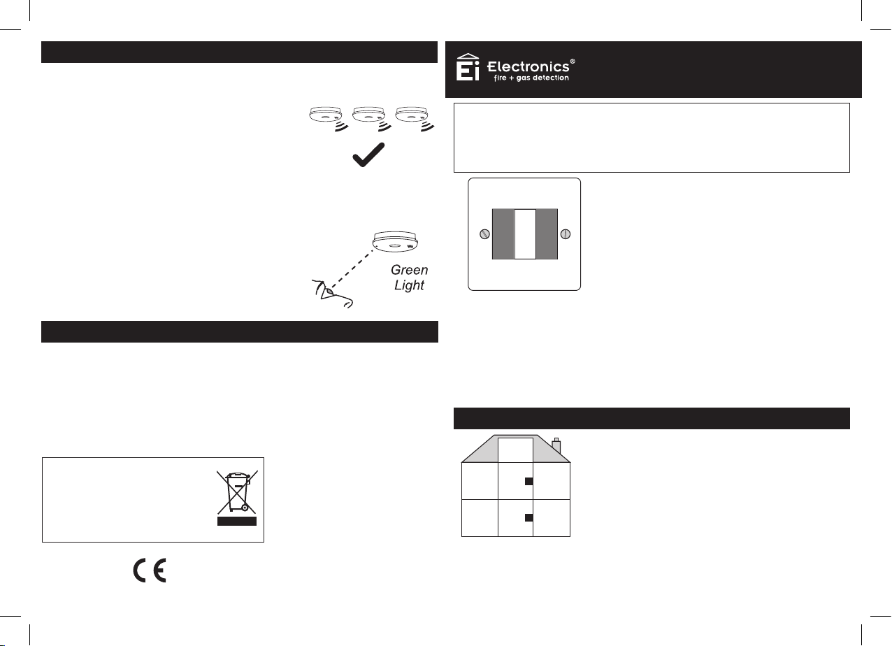
• Test Alarm – use to test the Smoke/Heat Alarms remotely.
1. Press the Test Alarm switch
Now check all the alarms sound and the red lights
on the covers flash rapidly. Then turn off the Test
Alarm switch.
This is equivalent to pressing the test button on all
alarms simultaneously.
It also checks that the remote control is receiving
mains power.
2. If the alarms do not sound
Check for the green mains light on the front cover
of the alarms.
If all alarms do not have the green mains light on,
check fuses, circuit breakers etc. (see Smoke/Heat
Alarm instructions for further details).
FIVE YEAR GUARANTEE
Ei Electronics guarantees this product for five years from date of purchase against any defects that
are due to faulty materials or workmanship. This guarantee only applies to normal conditions of use
and service, and does not include damage resulting from accident, neglect, misuse, unauthorised
dismantling, or contamination howsoever caused. This guarantee excludes incidental and consequential
damage. If this product should become defective within the guarantee period, it must be returned, with
proof of purchase, carefully packaged, with the problem clearly stated (see addresses below). We shall
at our discretion repair or replace the faulty unit. Do not interfere with the product or attempt to tamper
with it. This will invalidate the guarantee, but more importantly may expose the user to shock or fire
hazards. This guarantee is in addition to your statutory rights as a consumer.
The crossed out wheelie bin symbol that is on your
product indicates that this product should not be disposed
of via the normal household waste stream. Proper
disposal will prevent possible harm to the environment or
to human health. When disposing of this product please
separate it from other waste streams to ensure that it can
be recycled in an environmentally sound manner. For
more details on collection and proper disposal, please
contact your local government office or the retailer where
you purchased this product.
4
Aico Ltd. Mile End Business Park,
Maesbury Rd, Oswestry,
Shropshire SY10 8NN, U.K
Tel: 01691 664100
www.aico.co.uk
Ei Electronics. Shannon, Ireland.
Tel: +353 (0)61 471277
www.eielectronics.com
REMOTE CONTROL
SWITCH
INSTRUCTIONS
Model
Ei1529RC
WARNING: For use only with the following models:
Smoke/Heat/CO Alarms - 2100 Series, 140RC Series, 160RC Series, 160e Series,
Ei261ENRC & Ei261DENRC
Accessories - Ei128RBU, Ei169/160, MCP401RC
DO NOT use any other models with this remote control
Fire Alarms
Control Switch
The Remote Control is recommended for
use in systems comprising of three or more
interconnected Alarms.
The Remote Control should be wall mounted at
Locate
Alarm
Alarm
Silence
Test
Alarm
LOCATE ALARM:
standard light switch level (1.2m from floor level)
to allow easy access.
If alarms sound, press to allow the source of alarm to
be identified audibly.
SILENCE ALARM:
TEST ALARM:
Press to silence nuisance alarms.
Operate weekly to test the alarms. Can also be used
to give a manual alarm
MAINS CHECK:
TheTest Alarm switch will not sound the alarms in the
absence of mains power.
SITING
Position the Remote Control in a location that will allow it
to be easily accessed. In the majority of installations this
will be in a hallway, possibly next to the master bedroom.
Bedroom Landing
Hallway
If a metal back-box is used it must have a minimum depth of 35mm.
Up to four Ei1529RC System Remote Controls can be used in a system.
© Ei Electronics 2015
It should be installed at the standard light switch height
Bedroom
(1.2m from floor level).
The Remote Control can be surface mounted using
the mounting box provided or alternatively it can be
recessed into a standard back-box (not included).
1
P/N B16112 Rev3
Page 2
WIRING
WARNING: This Remote Control should be installed by a qualified electrician in
accordance with the Requirements for Electrical Installations published by the
IET as BS7671:2008 +A2:2013.
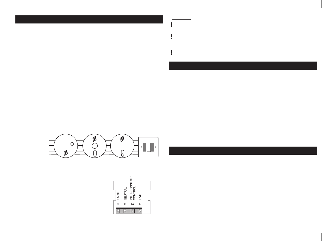
1. Disconnect the AC mains power supply from the circuit that is going to be
used to power the Smoke/Heat Alarms and the Remote Control.
2. Locate and install the Alarms as per the ‘Installer Instructions’ included with
the alarms.
3. Select a suitable location for the Remote Control as per the ‘SITING’ section
on page 1 of this leaflet.
4. Route the wiring (Live, Neutral, Interconnect/Control and Earth) to this point.
A minimum 0.75mm2 cable should be used.
5. Fix the mounting box provided to the wall for surface mounting or alternately,
fix a back box (not included) into the wall if recessed mounting is required.
6. Pass the wiring through an appropriate knockout in the mounting box or back-box.
7. Connect the wiring as shown in Figures 1 & 2 below.
(N.B. The Remote Control does not need to be earthed. However the terminal
marked with the earth symbol is provided for the convenience of the installer so that
any copper earth wire or cable coloured green & yellow, can be safely terminated).
Interconnect/Control
Live
Neutral
Earth
Figure 1
Note: The Ei1529RC Remote Control can be
wired from any location within the system.
8. Fix the Remote Control to the mounting
box or back-box.
9. Reconnect the AC mains power to the
circuit and check that the green mains
indicator lights on the Alarms are on.
10. Test the function of the Remote Control
as outlined in the ‘WEEKLY TESTING’
section on page 4 of this leaflet.
2
Figure 2
Fire Alarms
Control Switch
Locate
Alarm
Silence
Test
Alarm
Alarm
CAUTION
Ensure all wiring is correctly connected otherwise the Control Switch
and all connected units may be damaged.
Do not apply the high voltage insulation test to the wiring as all connected
units may be damaged. If it is necessary to check insulation, temporarily
remove all Alarms and the Ei1529RC switch.
If a metal back-box is used (for recessed mounting) it must have a minimum
depth of 35mm.
‘LOCATE’ & ‘SILENCE ALARM’ FUNCTIONS
• Locate Alarm – primarily used to identify the Alarm sensing fire.
When all the alarms are sounding due to a fire (or nuisance alarm):
Press and release the spring loaded Locate Alarm switch. This will silence
all the alarms except those sensing fire / CO.
This is a very useful feature. For example, consider twelve alarms sounding
simultaneously, then the unit sensing the fire can be identified audibly and
the premises evacuated or the problem quickly resolved.
• Silence Alarm - used to silence nuisance alarms. This should only be
pressed after the Locate switch has been used to identify the alarm that
triggered the system, and it is determined that no fire is present.
Do not Silence the alarms unless you are sure there is no fire.
(Typically the Alarms will be silenced for a period of 10 mins).
To Silence the alarms, press and release the Silence Alarm switch.
WHEN ALARMS ARE SOUNDING
What to do when the Alarms are sounding
1.If there is a fire, immediately evacuate the premises and telephone the
fire brigade from outside.
2. When the alarms are sounding and the cause is not obvious,
immediately press the ‘Locate Alarm’ switch. This will silence all the
alarms except those sensing fire themselves.
3. Locate the alarm(s) sensing fire audibly. Be careful, check doors are
not warm and that there is no sign of smoke before you open them (See
escape plan in Smoke/Heat Alarm instructions for further details).
4. If you are fully satisfied that there is no fire, but the smoke/heat alarm is
still continuing to alarm then press the ‘Silence Alarm’ switch.
3
 Loading...